EP3672011B1 - Regulierverfahren eines stromverteilungsnetzes - Google Patents
Regulierverfahren eines stromverteilungsnetzes Download PDFInfo
- Publication number
- EP3672011B1 EP3672011B1 EP19216819.3A EP19216819A EP3672011B1 EP 3672011 B1 EP3672011 B1 EP 3672011B1 EP 19216819 A EP19216819 A EP 19216819A EP 3672011 B1 EP3672011 B1 EP 3672011B1
- Authority
- EP
- European Patent Office
- Prior art keywords
- voltage
- frequency
- grid
- source
- network
- Prior art date
- Legal status (The legal status is an assumption and is not a legal conclusion. Google has not performed a legal analysis and makes no representation as to the accuracy of the status listed.)
- Active
Links
Images


Classifications
-
- H—ELECTRICITY
- H02—GENERATION; CONVERSION OR DISTRIBUTION OF ELECTRIC POWER
- H02J—ELECTRIC POWER NETWORKS; CIRCUIT ARRANGEMENTS OR SYSTEMS FOR SUPPLYING OR DISTRIBUTING ELECTRIC POWER; SYSTEMS FOR STORING ELECTRIC ENERGY
- H02J3/00—Circuit arrangements for AC mains or AC distribution networks
- H02J3/38—Arrangements for feeding a single network from two or more generators or sources in parallel; Arrangements for feeding already energised networks from additional generators or sources in parallel
- H02J3/381—Dispersed generators
-
- H—ELECTRICITY
- H02—GENERATION; CONVERSION OR DISTRIBUTION OF ELECTRIC POWER
- H02J—ELECTRIC POWER NETWORKS; CIRCUIT ARRANGEMENTS OR SYSTEMS FOR SUPPLYING OR DISTRIBUTING ELECTRIC POWER; SYSTEMS FOR STORING ELECTRIC ENERGY
- H02J3/00—Circuit arrangements for AC mains or AC distribution networks
- H02J3/001—Arrangements for handling faults or abnormalities, e.g. emergencies or contingencies
- H02J3/0014—Arrangements for handling faults or abnormalities, e.g. emergencies or contingencies for preventing or reducing power oscillations in networks
- H02J3/00142—Oscillations concerning frequency
-
- H—ELECTRICITY
- H02—GENERATION; CONVERSION OR DISTRIBUTION OF ELECTRIC POWER
- H02J—ELECTRIC POWER NETWORKS; CIRCUIT ARRANGEMENTS OR SYSTEMS FOR SUPPLYING OR DISTRIBUTING ELECTRIC POWER; SYSTEMS FOR STORING ELECTRIC ENERGY
- H02J3/00—Circuit arrangements for AC mains or AC distribution networks
- H02J3/001—Arrangements for handling faults or abnormalities, e.g. emergencies or contingencies
- H02J3/0014—Arrangements for handling faults or abnormalities, e.g. emergencies or contingencies for preventing or reducing power oscillations in networks
-
- H—ELECTRICITY
- H02—GENERATION; CONVERSION OR DISTRIBUTION OF ELECTRIC POWER
- H02J—ELECTRIC POWER NETWORKS; CIRCUIT ARRANGEMENTS OR SYSTEMS FOR SUPPLYING OR DISTRIBUTING ELECTRIC POWER; SYSTEMS FOR STORING ELECTRIC ENERGY
- H02J3/00—Circuit arrangements for AC mains or AC distribution networks
- H02J3/28—Arrangements for balancing of the load in networks by storage of energy
- H02J3/32—Arrangements for balancing of the load in networks by storage of energy using batteries or super capacitors with converting means
-
- H—ELECTRICITY
- H02—GENERATION; CONVERSION OR DISTRIBUTION OF ELECTRIC POWER
- H02J—ELECTRIC POWER NETWORKS; CIRCUIT ARRANGEMENTS OR SYSTEMS FOR SUPPLYING OR DISTRIBUTING ELECTRIC POWER; SYSTEMS FOR STORING ELECTRIC ENERGY
- H02J3/00—Circuit arrangements for AC mains or AC distribution networks
- H02J3/38—Arrangements for feeding a single network from two or more generators or sources in parallel; Arrangements for feeding already energised networks from additional generators or sources in parallel
- H02J3/46—Controlling the sharing of generated power between the generators, sources or networks
- H02J3/48—Controlling the sharing of active power
-
- H—ELECTRICITY
- H02—GENERATION; CONVERSION OR DISTRIBUTION OF ELECTRIC POWER
- H02J—ELECTRIC POWER NETWORKS; CIRCUIT ARRANGEMENTS OR SYSTEMS FOR SUPPLYING OR DISTRIBUTING ELECTRIC POWER; SYSTEMS FOR STORING ELECTRIC ENERGY
- H02J2101/00—Supply or distribution of decentralised, dispersed or local electric power generation
- H02J2101/20—Dispersed power generation using renewable energy sources
- H02J2101/22—Solar energy
- H02J2101/24—Photovoltaics
-
- H—ELECTRICITY
- H02—GENERATION; CONVERSION OR DISTRIBUTION OF ELECTRIC POWER
- H02J—ELECTRIC POWER NETWORKS; CIRCUIT ARRANGEMENTS OR SYSTEMS FOR SUPPLYING OR DISTRIBUTING ELECTRIC POWER; SYSTEMS FOR STORING ELECTRIC ENERGY
- H02J2101/00—Supply or distribution of decentralised, dispersed or local electric power generation
- H02J2101/20—Dispersed power generation using renewable energy sources
- H02J2101/28—Wind energy
-
- H—ELECTRICITY
- H02—GENERATION; CONVERSION OR DISTRIBUTION OF ELECTRIC POWER
- H02J—ELECTRIC POWER NETWORKS; CIRCUIT ARRANGEMENTS OR SYSTEMS FOR SUPPLYING OR DISTRIBUTING ELECTRIC POWER; SYSTEMS FOR STORING ELECTRIC ENERGY
- H02J3/00—Circuit arrangements for AC mains or AC distribution networks
- H02J3/28—Arrangements for balancing of the load in networks by storage of energy
-
- Y—GENERAL TAGGING OF NEW TECHNOLOGICAL DEVELOPMENTS; GENERAL TAGGING OF CROSS-SECTIONAL TECHNOLOGIES SPANNING OVER SEVERAL SECTIONS OF THE IPC; TECHNICAL SUBJECTS COVERED BY FORMER USPC CROSS-REFERENCE ART COLLECTIONS [XRACs] AND DIGESTS
- Y02—TECHNOLOGIES OR APPLICATIONS FOR MITIGATION OR ADAPTATION AGAINST CLIMATE CHANGE
- Y02E—REDUCTION OF GREENHOUSE GAS [GHG] EMISSIONS, RELATED TO ENERGY GENERATION, TRANSMISSION OR DISTRIBUTION
- Y02E10/00—Energy generation through renewable energy sources
- Y02E10/50—Photovoltaic [PV] energy
- Y02E10/56—Power conversion systems, e.g. maximum power point trackers
Definitions
- the present invention relates to a method for regulating an electrical distribution network.
- the present invention proposes a method for regulating an electrical distribution network independent of the primary reserve it has.
- the present invention proposes a regulation method making it possible to ensure the stability of the network whatever the state of the primary reserve.
- the method is particularly suitable for regulating a micro-grid, in particular a micro-grid having a high penetration rate of renewable energy.
- N-1 criterion a criterion which allows them to withstand the occurrence of a fault without major impact on the stability of the network and thus avoid a situation of general power outage ("Black- out” according to the Anglo-Saxon terminology).
- the interconnected networks pool their sources of electrical energy production and propose operating diagrams making it possible to react appropriately when a fault occurs on the network.
- compliance with the N-1 criterion includes the sizing of a primary energy reserve (“Spinning Reserve” according to Anglo-Saxon terminology) sufficient to respond to a given event and immediately within the framework of primary regulation.
- Primary energy reserve Scopinning Reserve
- This primary regulation notably involves an adjustment, by droop, of the frequency or voltage of the electrical distribution network in order to respond to a load call or compensate for a fault occurring on the electrical distribution network.
- a so-called secondary regulation can then intervene later in order to restore the electrical distribution network to its initial state.
- the primary reserve is relatively flexible when it is implemented by predictable and stable energy production sources such as generators.
- intermittent sources generally have only low inertia, and react in a dispersed and uncoordinated manner upon the occurrence of a fault or a load inrush, thus exacerbating the instability of the network. Such behavior of intermittent sources does not ensure the stability of the network.
- droop regulation can generate flow variations and thus cause damage to all the equipment ensuring the operation of the network.
- An object of the present invention is to propose a method for controlling a generator making it possible to guarantee the stability of the electrical distribution network.
- Another object of the present invention is to propose a method for controlling a generator making it possible to increase the rate of penetration of renewable energy sources.
- Another object of the present invention is to propose a method for controlling a generator making it possible to guarantee the stability of the network also when the primary reserve is insufficient.
- Another object of the present invention is to propose a method for controlling a generator offering protection against the degradation of the various equipment, in particular the electrosensitive equipment, ensuring the operation of the network.
- the objects of the present invention are, at least in part, achieved by a method for regulating an electrical distribution network which comprises an electrical source called the main source, among one or more electrical sources, configured to impose on the network the voltage V and the frequency f of a power P circulating on the of the network and to which one or more loads are connected.
- the method comprises, in the event of a variation of one of the frequency f or the voltage V detected on the network, during a primary regulation, a step of adjustment, by the main source, of the other of the frequency f and voltage V so as to keep the ratio of voltage V to frequency f essentially constant.
- Essentially constant is understood to mean a ratio that can exhibit variations of plus or minus 5% around a setpoint value.
- maintaining the V/f ratio makes it possible to ensure the stability of the network without consideration relating to the primary reserve.
- V/F ratio kept essentially constant makes it possible to maintain a constant flux in the loads, in particular electrosensitive equipment, and thus avoid wear or overheating of a motor of a load.
- the method according to the present invention can be implemented on an already existing electrical distribution network.
- the main source comprises a regulator making it possible to execute the adjustment step.
- the regulator measures the frequency f and the voltage V of the distribution network, advantageously, the measurement is carried out at regular time intervals.
- the main source is intermittent.
- the main source may not impose power, and include for example a motor whose shaft is not connected.
- the main source may include an energy storage system, for example a flywheel, a battery, etc.
- the main source is a renewable energy source
- the renewable energy source comprises at least one source chosen from: a solar energy source, a wind energy source, a energy source.
- the main source comprises an inverter provided with a control law giving it the behavior of a synchronous generator so that the main source forms a virtual synchronous generator.
- the at least one source also comprises other sources, advantageously intermittent sources, even more advantageously renewable energy sources.
- the primary regulation is followed by a secondary regulation making it possible to restore the frequency f and the voltage V of the network to predetermined values.
- one of the electrical sources of the electrical distribution network has a primary energy reserve, the method comprising, prior to the adjustment step, a step of evaluating the primary reserve at with regard to a load call or a fault likely to occur on the network.
- the evaluation step when the primary reserve is evaluated as sufficient to respond to a load call or to a fault, the evaluation step also includes the implementation of a regulation based on the injection of at least part of the primary reserve on the network so as to respond to the load demand or to the fault.
- the invention also relates to a computer program, comprising instructions which, when it is executed by a computer, lead to the implementation of the regulation method according to the invention.
- the invention also relates to an electrical source configured to impose on a network the voltage V and the frequency f of a power P circulating on said network, and provided with the computer program according to the present invention.
- the present invention described in detail below implements a method for regulating an electrical distribution network provided with a source, called the main source, among one or more energy sources, configured to impose on the network the voltage V and the frequency f of a power P circulating on the network and intended to be consumed by loads.
- the main source is adapted to maintain constant the ratio of the voltage V and the frequency f of the power P circulating on the network.
- electrical source is meant any source capable of delivering or not delivering an electric current, of imposing a voltage.
- an electrical source can include, and is not limited to, a synchronous generator, an asynchronous generator, a voltage source.
- the present invention although described in the context of electrical distribution networks in general, can advantageously be implemented within a micro-grid.
- micro-grid By “micro-grid” (“microgrid” according to the Anglo-Saxon terminology), we mean a local electrical network intended to produce and distribute electrical energy in isolated regions far from the major centers of electrical energy production.
- the isolated regions are, for example, islands, mountainous regions, or else desert zones.
- the microgrid principle also applies when a building, district, campus, or other entity connected to a large distribution network wishes to manage its energy production differently and increase its resilience capacity.
- micro-grids operate autonomously (in island mode, without connection to the public grid), and are close to consumption areas (loads). Thus, the losses inherent in long-distance distribution networks are limited.
- an “electrical distribution network” may comprise an electrical distribution network or an electrical transport network or even an electrical distribution network.
- the figure 1 represents an electrical distribution network 10.
- the electrical distribution network includes one or more electrical sources.
- one or more electrical sources is a so-called main source 20 which is configured to impose on the network the voltage V and the frequency f of a power P circulating (or distributed) on the electrical distribution network 10.
- the main source 20 can form the network.
- the main source 20 can include a synchronous generator, in particular a generator.
- main source 20 may include an intermittent power source.
- the intermittent energy source can comprise a renewable energy source, and for example comprise photovoltaic panels, wind turbines, tidal turbines, thermodynamic machines.
- the intermittent energy source may be provided with an inverter ("inverter” according to the Anglo-Saxon terminology) provided with a control law giving the intermittent energy source the behavior of a synchronous generator so that the main source forms a virtual synchronous generator.
- inverter inverter
- control law giving the intermittent energy source the behavior of a synchronous generator so that the main source forms a virtual synchronous generator.
- One or more sources may also include other sources, advantageously intermittent sources 21, even more advantageously renewable energy sources.
- renewable energy sources can include photovoltaic panels, wind turbines, tidal turbines, thermodynamic machines.
- the at least one source can comprise one or more batteries 22.
- one or more sources can comprise one or more generators 23, for example synchronous generators, asynchronous generators, or a combination of the two.
- the method according to the present invention comprises an adjustment step, within the framework of a primary regulation, which essentially keeps the ratio of the voltage V to the frequency f constant.
- the adjustment step comprises an adjustment of the voltage V so as to keep the ratio of the voltage V to the frequency f essentially constant.
- the adjustment step comprises an adjustment of the frequency f so as to keep the ratio of the voltage V to the frequency f essentially constant.
- Such frequency and/or voltage variations of the power P circulating on the electrical distribution network can occur during load inrush or when a fault appears.
- This regulation is implemented by the main source which is able to form the network.
- the main source 20 can comprise a regulator R configured to ensure the regulation according to the terms of the invention.
- the regulator can measure the frequency f and the voltage V of the electrical power P.
- the measurement is carried out at regular time intervals, for example every second.
- This measurement makes it possible to establish the state of the network and also to detect the occurrence of an event such as a load call or the appearance of a fault.
- the picture 2 is a schematic representation of the implementation of the regulation according to the present invention.
- the picture 2 represents a main source 20 connected to an electrical distribution network 10 distributing a power P to a load 30.
- the main source 20 is associated with a regulator provided with sub-modules, and in particular a frequency regulation module 20a, a voltage regulation module 20b and a control module 20c of the frequency regulation module 20a and of the voltage regulation module 20b.
- the frequency regulation module 20a requires the main source 20 to adjust the frequency of a power circulating on the network to a given frequency.
- the voltage regulation module 20b requires the main source 20 to adjust the voltage of a power circulating on the network to a given voltage.
- the control module 20c indicates to the frequency module 20a and to the voltage regulation module 20b, respectively, the frequency f and the voltage V that the primary source must impose on the network.
- the measurement of the voltage V and of the frequency f of the power P circulating on the network are measured by the control module 20c.
- the regulation thus proposed makes it possible to preserve a balance between power consumed and power produced at all times independently of the state of any primary reserve.
- Regulation may also incorporate frequency and/or voltage modulation by droop if sufficient primary reserve is immediately available to respond to a given event.
- the regulation proposed according to the present invention is also advantageous insofar as it does not require communication between the various equipment items, and in particular the energy sources, connected to the network.
- the primary regulation can be followed by a secondary regulation making it possible to restore the frequency f and the voltage V of the network to predetermined values.
- the invention also relates to a computer program, comprising instructions which, when it is executed by a computer, lead to the implementation of the method according to the present invention.
- the invention also relates to an energy source configured to impose on a network the voltage V and the frequency f of a power P circulating on said network, and provided with the computer program according to the present invention.
- the method according to the present invention has been the subject of various simulations.
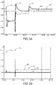
- the inventors have simulated the behavior of a combination of a generator forming the network (or “grid former” according to Anglo-Saxon terminology) and of a synchronous generator.
- Figure 3A represents the voltage delivered (vertical axis) as a function of time (horizontal axis) by the generator forming the network (curve A1) and by the synchronous generator (curve B1).
- the Figure 3B represents the active power delivered (vertical axis) as a function of time (horizontal axis) by the generator forming the network (curve A2) and by the synchronous generator (curve B2).
- the Fig. 3C represents the reactive power delivered (vertical axis) as a function of time (horizontal axis) by the generator forming the network (curve A3) and by the synchronous generator (curve B3).
- the 3d figure represents the frequency f delivered (vertical axis) as a function of time (horizontal axis) by generator forming the network (curve A4) and by the synchronous generator (curve B4).
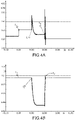
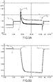
- the inventors have simulated the behavior of an inverter forming the network.
- the figure 4A represents the active power delivered by the inverter (vertical axis) as a function of time (horizontal axis).
- the figure 4B represents the power frequency delivered by the inverter (vertical axis) as a function of time (horizontal axis).
- the Fig. 4C represents the current delivered by the inverter (vertical axis) as a function of time (horizontal axis).
- the 4D figure represents the voltage delivered by the inverter (vertical axis) as a function of time (horizontal axis).
- a fault appears on the network.
- the latter takes the form of a load call of 660 kW ( figure 4A ).
- the adjustment is carried out in such a way as to keep the V/f ratio constant according to the terms of the present invention, and thus ensure the stability of the network.
- the secondary regulation phase begins from time t 2 in order to restore the network to a state imposed by the operator.
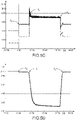
- the inventors have simulated the behavior of two inverters capable of forming the network.
- the figure 5A represents the active power (vertical axis) delivered by each of the inverters as a function of time (horizontal axis).
- the figure 5B represents the power frequency (vertical axis) delivered by each of the inverters as a function of time (horizontal axis).
- the Fig. 5C represents the current delivered (vertical axis) delivered by each of the inverters as a function of time (horizontal axis).
- the figure 5D represents the voltage delivered (vertical axis) delivered by each of the inverters as a function of time (horizontal axis).
- the two inverters again regulate the frequency ( figure 5B ) and voltage ( figure 5D ) so as to keep the V/f ratio constant according to the terms of the present invention, and thus ensure the stability of the network.
- the secondary regulation phase begins from time t 2 in order to restore the network to a state imposed by the operator.
Landscapes
- Engineering & Computer Science (AREA)
- Power Engineering (AREA)
- Supply And Distribution Of Alternating Current (AREA)
- Remote Monitoring And Control Of Power-Distribution Networks (AREA)
Claims (12)
- Verfahren zur Regelung eines Stromverteilungsnetzes (10), das unter einer oder mehreren Stromquellen eine Stromquelle, Hauptquelle (20) genannt, umfasst, die dazu ausgelegt ist, dem Netz die Spannung V und die Frequenz f einer Leistung P vorzugeben, die im Netz fließt, an welches eine oder mehrere Lasten angeschlossen sind,
dadurch gekennzeichnet, dass
im Falle einer Änderung eines aus im Netz erfasster Frequenz f und Spannung V das Verfahren bei einer Primärregelung einen Schritt umfasst, bei dem das andere aus Frequenz f und Spannung V mittels der Hauptquelle (20) so abgeglichen wird, dass das Verhältnis der Spannung V zur Frequenz f konstant gehalten wird. - Verfahren nach Anspruch 1, wobei die Hauptquelle (20) einen Regler zum Durchführen des Abgleichs enthält.
- Verfahren nach Anspruch 2, wobei der Regler die Frequenz f und die Spannung V des Verteilungsnetzes misst, wobei die Messungen in regelmäßigen Zeitintervallen durchgeführt werden.
- Verfahren nach einem der Ansprüche 1 bis 3, wobei die Hauptquelle (20) intermittierend ist.
- Verfahren nach Anspruch 4, wobei die Hauptquelle (20) eine erneuerbare Energiequelle ist, wobei insbesondere die erneuerbare Energiequelle zumindest eine Quelle, ausgewählt aus Solarenergiequelle, Windenergiequelle, Energiequelle, umfasst.
- Verfahren nach Anspruch 4 oder 5, wobei die Hauptquelle (20) einen Wechselrichter mit einem Regelungsgrundsatz enthält, der diesem ein Synchrongeneratorverhalten verleiht, so dass die Hauptquelle (20) einen virtuellen Synchrongenerator bildet.
- Verfahren nach einem der Ansprüche 1 bis 6, wobei das Stromverteilungsnetz (10) auch andere Quellen, vorteilhafterweise intermittierende Quellen (21), oder erneuerbare Energiequellen umfasst.
- Verfahren nach einem der Ansprüche 1 bis 7, wobei auf die Primärregelung eine Sekundärregelung folgt, bei der die Frequenz f und die Spannung V des Netzes auf vorbestimmte Werte zurückgesetzt werden können.
- Verfahren nach einem der Ansprüche 1 bis 8, wobei eine der Stromquellen des Stromverteilungsnetzes (10) über eine Primärenergiereserve verfügt, wobei das Verfahren vor dem Schritt des Abgleichs einen Schritt der Bewertung der Primärreserve im Hinblick auf einen Lastabruf oder einen Fehler, der im Netz auftreten kann, umfasst.
- Verfahren nach Anspruch 9, wobei dann, wenn die Primärreserve als ausreichend bewertet wird, um auf einen Lastabruf oder einen Fehler zu reagieren, der Bewertungsschritt auch die Durchführung einer Regelung umfasst, die auf der Einspeisung zumindest eines Teils der Primärreserve in das Netz beruht, um auf den Lastabruf oder den Fehler zu reagieren.
- Computerprogramm, das Anweisungen enthält, die, wenn es von einem Rechner ausgeführt wird, zur Durchführung des Verfahrens nach einem der Ansprüche 1 bis 10 führen.
- Stromquelle, die dazu ausgelegt ist, einem Netz die Spannung V und die Frequenz f einer in diesem Netz fließenden Leistung P vorzugeben, und die mit dem Computerprogramm nach Anspruch 11 versehen ist.
Applications Claiming Priority (1)
| Application Number | Priority Date | Filing Date | Title |
|---|---|---|---|
| FR1873570A FR3090916B1 (fr) | 2018-12-20 | 2018-12-20 | Procede de regulation d’un reseau de distribution electrique |
Publications (2)
| Publication Number | Publication Date |
|---|---|
| EP3672011A1 EP3672011A1 (de) | 2020-06-24 |
| EP3672011B1 true EP3672011B1 (de) | 2022-10-26 |
Family
ID=67185134
Family Applications (1)
| Application Number | Title | Priority Date | Filing Date |
|---|---|---|---|
| EP19216819.3A Active EP3672011B1 (de) | 2018-12-20 | 2019-12-17 | Regulierverfahren eines stromverteilungsnetzes |
Country Status (4)
| Country | Link |
|---|---|
| US (1) | US11728652B2 (de) |
| EP (1) | EP3672011B1 (de) |
| CN (1) | CN111355248B (de) |
| FR (1) | FR3090916B1 (de) |
Family Cites Families (18)
| Publication number | Priority date | Publication date | Assignee | Title |
|---|---|---|---|---|
| US7481069B2 (en) * | 2005-07-28 | 2009-01-27 | Carrier Corporation | Controlling a voltage-to-frequency ratio for a variable speed drive in refrigerant systems |
| US20100138070A1 (en) * | 2009-02-26 | 2010-06-03 | Ronald Beaudoin | System and method for improving power grid stability |
| EP2600479A1 (de) * | 2011-12-02 | 2013-06-05 | ABB Research Ltd. | Steuerung eines Stromnetzes mit inselartigem Betrieb |
| US9400330B2 (en) * | 2012-10-19 | 2016-07-26 | Schweitzer Engineering Laboratories, Inc. | Manipulation resilient time distribution network |
| US9042141B2 (en) * | 2013-02-07 | 2015-05-26 | Caterpillar Inc. | Control of energy storage system inverter system in a microgrid application |
| CN103345869B (zh) * | 2013-06-25 | 2016-01-06 | 武汉理工大学 | 基于复合能源并网发电的千瓦级船舶能源系统实验平台 |
| US9593672B2 (en) * | 2013-08-07 | 2017-03-14 | Siemens Aktiengesellschaft | Isochronous wind turbine generator capable of stand-alone operation |
| CN103545810B (zh) * | 2013-11-12 | 2015-07-15 | 国家电网公司 | 基于小信号稳定分析的微电网逆变器下垂自动控制方法 |
| CA2886409C (en) * | 2013-12-06 | 2016-03-22 | Rajiv Kumar Varma | Multivariable modulator controller for power generation facility |
| CN105515007A (zh) * | 2014-10-18 | 2016-04-20 | 杨利 | 电力系统电压频率调节控制器 |
| US9444257B2 (en) * | 2014-12-02 | 2016-09-13 | Osisoft, Llc | Hierarchical control of micro-grids |
| US9960637B2 (en) * | 2015-07-04 | 2018-05-01 | Sunverge Energy, Inc. | Renewable energy integrated storage and generation systems, apparatus, and methods with cloud distributed energy management services |
| CN106385054B (zh) * | 2016-11-22 | 2019-02-15 | 国网辽宁省电力有限公司锦州供电公司 | 分布式光伏逆变器运行控制方法 |
| IT201600131878A1 (it) * | 2016-12-28 | 2018-06-28 | Electro Power Systems Mfg S R L | Sistema di controllo di microreti di produzione e distribuzione di energia elettrica proveniente da più fonti di produzione di tipo diverso, e relativo metodo di controllo |
| CN107273586A (zh) * | 2017-05-25 | 2017-10-20 | 哈尔滨工程大学 | 一种针对太阳能船舶的光伏波动功率低成本抑制方法 |
| US10651654B2 (en) * | 2017-11-07 | 2020-05-12 | State Grid Corporation Of China | Model predictive controller for autonomous hybrid microgrids |
| CN108631320A (zh) * | 2018-06-01 | 2018-10-09 | 三峡大学 | 一种基于前馈鲁棒控制的微电网电压控制方法 |
| CN108808699A (zh) * | 2018-07-10 | 2018-11-13 | 华北电力大学(保定) | 一种适用于双向储能设备的双象限频率特性分析方法 |
-
2018
- 2018-12-20 FR FR1873570A patent/FR3090916B1/fr not_active Expired - Fee Related
-
2019
- 2019-12-17 EP EP19216819.3A patent/EP3672011B1/de active Active
- 2019-12-18 US US16/719,115 patent/US11728652B2/en active Active
- 2019-12-20 CN CN201911327435.6A patent/CN111355248B/zh active Active
Also Published As
| Publication number | Publication date |
|---|---|
| EP3672011A1 (de) | 2020-06-24 |
| FR3090916B1 (fr) | 2022-06-03 |
| CN111355248B (zh) | 2025-03-25 |
| US20200203955A1 (en) | 2020-06-25 |
| US11728652B2 (en) | 2023-08-15 |
| CN111355248A (zh) | 2020-06-30 |
| FR3090916A1 (fr) | 2020-06-26 |
Similar Documents
| Publication | Publication Date | Title |
|---|---|---|
| EP3185386B1 (de) | Kontrollverfahren eines elektrischen mikroverteilungsnetzes | |
| EP3208907B1 (de) | Steuerungsverfahren eines virtuellen generators | |
| Samuelsson et al. | On speed stability | |
| Vournas et al. | Postmortem analysis and data validation in the wake of the 2004 Athens blackout | |
| US10819269B2 (en) | DC integration of photovoltaic and DFIG wind turbine generation with electric storage | |
| Tuckey et al. | Decentralized control of a microgrid | |
| Dozein et al. | Frequency response capabilities of utility-scale battery energy storage systems, with application to the august 2018 separation event in australia | |
| FR3020190A1 (fr) | Procede de controle et regulation d'un reseau electrique | |
| EP3627649B1 (de) | Verfahren zur steuerung eines generators | |
| EP3672011B1 (de) | Regulierverfahren eines stromverteilungsnetzes | |
| Bawayan et al. | Mitigating low fault current in microgrids through renewables-battery hybrid units | |
| EP3731398A1 (de) | Steuerverfahren eines gleichstrom-wechselstrom-wandlers | |
| Frack et al. | Control-strategy design for frequency control in autonomous smart microgrids | |
| EP4203222B1 (de) | Verfahren zur gemeinsamen spannungsregelung in einem mittelspannungszweig und niederspannungszweig mit einem dreiphasigen niederspannungszweig | |
| CA3183945A1 (fr) | Procede de pilotage de charge et de decharge d'une pluralite de dispositifs de stockage d'energie electrique | |
| Kumar et al. | Dynamic grid support system for mitigation of impact of high penetration solar PV into grid | |
| US11437817B2 (en) | Method and device for driving an electricity production assembly, and associated production assembly | |
| Potamianakis et al. | Aggregation of wind farms in distribution networks | |
| Almeida et al. | Electric vehicles in automatic generation control for systems with large integration of renewables | |
| EP2533391B1 (de) | Multi-Source-Steuerungssystem von Stromgeneratoren | |
| FR3069110A1 (fr) | Procede de commande d'une pluralite d'accumulateurs | |
| Aktarujjaman et al. | Dynamics of a hydro-wind hybrid isolated power system | |
| FR2999029A1 (fr) | Dispositif et procede de regulation de l'alimentation electrique d'un reseau ayant une source photovoltaique. | |
| Asber et al. | Transient behavior of a distribution network incorporating decentralized generation | |
| EP3800777A1 (de) | Änderung der parameterwerte des steuergesetzes eines generators |
Legal Events
| Date | Code | Title | Description |
|---|---|---|---|
| PUAI | Public reference made under article 153(3) epc to a published international application that has entered the european phase |
Free format text: ORIGINAL CODE: 0009012 |
|
| STAA | Information on the status of an ep patent application or granted ep patent |
Free format text: STATUS: THE APPLICATION HAS BEEN PUBLISHED |
|
| AK | Designated contracting states |
Kind code of ref document: A1 Designated state(s): AL AT BE BG CH CY CZ DE DK EE ES FI FR GB GR HR HU IE IS IT LI LT LU LV MC MK MT NL NO PL PT RO RS SE SI SK SM TR |
|
| AX | Request for extension of the european patent |
Extension state: BA ME |
|
| STAA | Information on the status of an ep patent application or granted ep patent |
Free format text: STATUS: REQUEST FOR EXAMINATION WAS MADE |
|
| 17P | Request for examination filed |
Effective date: 20201120 |
|
| RBV | Designated contracting states (corrected) |
Designated state(s): AL AT BE BG CH CY CZ DE DK EE ES FI FR GB GR HR HU IE IS IT LI LT LU LV MC MK MT NL NO PL PT RO RS SE SI SK SM TR |
|
| REG | Reference to a national code |
Ref country code: DE Ref legal event code: R079 Ref document number: 602019021065 Country of ref document: DE Free format text: PREVIOUS MAIN CLASS: H02J0003240000 Ipc: H02J0003460000 |
|
| GRAJ | Information related to disapproval of communication of intention to grant by the applicant or resumption of examination proceedings by the epo deleted |
Free format text: ORIGINAL CODE: EPIDOSDIGR1 |
|
| GRAP | Despatch of communication of intention to grant a patent |
Free format text: ORIGINAL CODE: EPIDOSNIGR1 |
|
| GRAP | Despatch of communication of intention to grant a patent |
Free format text: ORIGINAL CODE: EPIDOSNIGR1 |
|
| STAA | Information on the status of an ep patent application or granted ep patent |
Free format text: STATUS: GRANT OF PATENT IS INTENDED |
|
| RIC1 | Information provided on ipc code assigned before grant |
Ipc: H02J 3/48 20060101ALI20220429BHEP Ipc: H02J 3/38 20060101ALI20220429BHEP Ipc: H02J 3/28 20060101ALI20220429BHEP Ipc: H02J 3/24 20060101ALI20220429BHEP Ipc: H02J 3/46 20060101AFI20220429BHEP |
|
| INTG | Intention to grant announced |
Effective date: 20220524 |
|
| GRAS | Grant fee paid |
Free format text: ORIGINAL CODE: EPIDOSNIGR3 |
|
| GRAA | (expected) grant |
Free format text: ORIGINAL CODE: 0009210 |
|
| STAA | Information on the status of an ep patent application or granted ep patent |
Free format text: STATUS: THE PATENT HAS BEEN GRANTED |
|
| AK | Designated contracting states |
Kind code of ref document: B1 Designated state(s): AL AT BE BG CH CY CZ DE DK EE ES FI FR GB GR HR HU IE IS IT LI LT LU LV MC MK MT NL NO PL PT RO RS SE SI SK SM TR |
|
| REG | Reference to a national code |
Ref country code: GB Ref legal event code: FG4D Free format text: NOT ENGLISH |
|
| REG | Reference to a national code |
Ref country code: CH Ref legal event code: EP |
|
| REG | Reference to a national code |
Ref country code: AT Ref legal event code: REF Ref document number: 1527769 Country of ref document: AT Kind code of ref document: T Effective date: 20221115 |
|
| REG | Reference to a national code |
Ref country code: DE Ref legal event code: R096 Ref document number: 602019021065 Country of ref document: DE |
|
| REG | Reference to a national code |
Ref country code: IE Ref legal event code: FG4D Free format text: LANGUAGE OF EP DOCUMENT: FRENCH |
|
| REG | Reference to a national code |
Ref country code: LT Ref legal event code: MG9D |
|
| REG | Reference to a national code |
Ref country code: NL Ref legal event code: MP Effective date: 20221026 |
|
| REG | Reference to a national code |
Ref country code: AT Ref legal event code: MK05 Ref document number: 1527769 Country of ref document: AT Kind code of ref document: T Effective date: 20221026 |
|
| PG25 | Lapsed in a contracting state [announced via postgrant information from national office to epo] |
Ref country code: NL Free format text: LAPSE BECAUSE OF FAILURE TO SUBMIT A TRANSLATION OF THE DESCRIPTION OR TO PAY THE FEE WITHIN THE PRESCRIBED TIME-LIMIT Effective date: 20221026 |
|
| PG25 | Lapsed in a contracting state [announced via postgrant information from national office to epo] |
Ref country code: SE Free format text: LAPSE BECAUSE OF FAILURE TO SUBMIT A TRANSLATION OF THE DESCRIPTION OR TO PAY THE FEE WITHIN THE PRESCRIBED TIME-LIMIT Effective date: 20221026 Ref country code: PT Free format text: LAPSE BECAUSE OF FAILURE TO SUBMIT A TRANSLATION OF THE DESCRIPTION OR TO PAY THE FEE WITHIN THE PRESCRIBED TIME-LIMIT Effective date: 20230227 Ref country code: NO Free format text: LAPSE BECAUSE OF FAILURE TO SUBMIT A TRANSLATION OF THE DESCRIPTION OR TO PAY THE FEE WITHIN THE PRESCRIBED TIME-LIMIT Effective date: 20230126 Ref country code: LT Free format text: LAPSE BECAUSE OF FAILURE TO SUBMIT A TRANSLATION OF THE DESCRIPTION OR TO PAY THE FEE WITHIN THE PRESCRIBED TIME-LIMIT Effective date: 20221026 Ref country code: FI Free format text: LAPSE BECAUSE OF FAILURE TO SUBMIT A TRANSLATION OF THE DESCRIPTION OR TO PAY THE FEE WITHIN THE PRESCRIBED TIME-LIMIT Effective date: 20221026 Ref country code: ES Free format text: LAPSE BECAUSE OF FAILURE TO SUBMIT A TRANSLATION OF THE DESCRIPTION OR TO PAY THE FEE WITHIN THE PRESCRIBED TIME-LIMIT Effective date: 20221026 Ref country code: AT Free format text: LAPSE BECAUSE OF FAILURE TO SUBMIT A TRANSLATION OF THE DESCRIPTION OR TO PAY THE FEE WITHIN THE PRESCRIBED TIME-LIMIT Effective date: 20221026 |
|
| PG25 | Lapsed in a contracting state [announced via postgrant information from national office to epo] |
Ref country code: RS Free format text: LAPSE BECAUSE OF FAILURE TO SUBMIT A TRANSLATION OF THE DESCRIPTION OR TO PAY THE FEE WITHIN THE PRESCRIBED TIME-LIMIT Effective date: 20221026 Ref country code: PL Free format text: LAPSE BECAUSE OF FAILURE TO SUBMIT A TRANSLATION OF THE DESCRIPTION OR TO PAY THE FEE WITHIN THE PRESCRIBED TIME-LIMIT Effective date: 20221026 Ref country code: LV Free format text: LAPSE BECAUSE OF FAILURE TO SUBMIT A TRANSLATION OF THE DESCRIPTION OR TO PAY THE FEE WITHIN THE PRESCRIBED TIME-LIMIT Effective date: 20221026 Ref country code: IS Free format text: LAPSE BECAUSE OF FAILURE TO SUBMIT A TRANSLATION OF THE DESCRIPTION OR TO PAY THE FEE WITHIN THE PRESCRIBED TIME-LIMIT Effective date: 20230226 Ref country code: HR Free format text: LAPSE BECAUSE OF FAILURE TO SUBMIT A TRANSLATION OF THE DESCRIPTION OR TO PAY THE FEE WITHIN THE PRESCRIBED TIME-LIMIT Effective date: 20221026 Ref country code: GR Free format text: LAPSE BECAUSE OF FAILURE TO SUBMIT A TRANSLATION OF THE DESCRIPTION OR TO PAY THE FEE WITHIN THE PRESCRIBED TIME-LIMIT Effective date: 20230127 |
|
| REG | Reference to a national code |
Ref country code: DE Ref legal event code: R097 Ref document number: 602019021065 Country of ref document: DE |
|
| PG25 | Lapsed in a contracting state [announced via postgrant information from national office to epo] |
Ref country code: SM Free format text: LAPSE BECAUSE OF FAILURE TO SUBMIT A TRANSLATION OF THE DESCRIPTION OR TO PAY THE FEE WITHIN THE PRESCRIBED TIME-LIMIT Effective date: 20221026 Ref country code: RO Free format text: LAPSE BECAUSE OF FAILURE TO SUBMIT A TRANSLATION OF THE DESCRIPTION OR TO PAY THE FEE WITHIN THE PRESCRIBED TIME-LIMIT Effective date: 20221026 Ref country code: EE Free format text: LAPSE BECAUSE OF FAILURE TO SUBMIT A TRANSLATION OF THE DESCRIPTION OR TO PAY THE FEE WITHIN THE PRESCRIBED TIME-LIMIT Effective date: 20221026 Ref country code: DK Free format text: LAPSE BECAUSE OF FAILURE TO SUBMIT A TRANSLATION OF THE DESCRIPTION OR TO PAY THE FEE WITHIN THE PRESCRIBED TIME-LIMIT Effective date: 20221026 Ref country code: CZ Free format text: LAPSE BECAUSE OF FAILURE TO SUBMIT A TRANSLATION OF THE DESCRIPTION OR TO PAY THE FEE WITHIN THE PRESCRIBED TIME-LIMIT Effective date: 20221026 |
|
| REG | Reference to a national code |
Ref country code: CH Ref legal event code: PL |
|
| REG | Reference to a national code |
Ref country code: BE Ref legal event code: MM Effective date: 20221231 |
|
| PG25 | Lapsed in a contracting state [announced via postgrant information from national office to epo] |
Ref country code: SK Free format text: LAPSE BECAUSE OF FAILURE TO SUBMIT A TRANSLATION OF THE DESCRIPTION OR TO PAY THE FEE WITHIN THE PRESCRIBED TIME-LIMIT Effective date: 20221026 Ref country code: LU Free format text: LAPSE BECAUSE OF NON-PAYMENT OF DUE FEES Effective date: 20221217 Ref country code: AL Free format text: LAPSE BECAUSE OF FAILURE TO SUBMIT A TRANSLATION OF THE DESCRIPTION OR TO PAY THE FEE WITHIN THE PRESCRIBED TIME-LIMIT Effective date: 20221026 |
|
| PLBE | No opposition filed within time limit |
Free format text: ORIGINAL CODE: 0009261 |
|
| STAA | Information on the status of an ep patent application or granted ep patent |
Free format text: STATUS: NO OPPOSITION FILED WITHIN TIME LIMIT |
|
| 26N | No opposition filed |
Effective date: 20230727 |
|
| PG25 | Lapsed in a contracting state [announced via postgrant information from national office to epo] |
Ref country code: LI Free format text: LAPSE BECAUSE OF NON-PAYMENT OF DUE FEES Effective date: 20221231 Ref country code: IE Free format text: LAPSE BECAUSE OF NON-PAYMENT OF DUE FEES Effective date: 20221217 Ref country code: CH Free format text: LAPSE BECAUSE OF NON-PAYMENT OF DUE FEES Effective date: 20221231 |
|
| PG25 | Lapsed in a contracting state [announced via postgrant information from national office to epo] |
Ref country code: SI Free format text: LAPSE BECAUSE OF FAILURE TO SUBMIT A TRANSLATION OF THE DESCRIPTION OR TO PAY THE FEE WITHIN THE PRESCRIBED TIME-LIMIT Effective date: 20221026 Ref country code: BE Free format text: LAPSE BECAUSE OF NON-PAYMENT OF DUE FEES Effective date: 20221231 |
|
| PG25 | Lapsed in a contracting state [announced via postgrant information from national office to epo] |
Ref country code: HU Free format text: LAPSE BECAUSE OF FAILURE TO SUBMIT A TRANSLATION OF THE DESCRIPTION OR TO PAY THE FEE WITHIN THE PRESCRIBED TIME-LIMIT; INVALID AB INITIO Effective date: 20191217 |
|
| PG25 | Lapsed in a contracting state [announced via postgrant information from national office to epo] |
Ref country code: CY Free format text: LAPSE BECAUSE OF FAILURE TO SUBMIT A TRANSLATION OF THE DESCRIPTION OR TO PAY THE FEE WITHIN THE PRESCRIBED TIME-LIMIT Effective date: 20221026 |
|
| PG25 | Lapsed in a contracting state [announced via postgrant information from national office to epo] |
Ref country code: MK Free format text: LAPSE BECAUSE OF FAILURE TO SUBMIT A TRANSLATION OF THE DESCRIPTION OR TO PAY THE FEE WITHIN THE PRESCRIBED TIME-LIMIT Effective date: 20221026 Ref country code: IT Free format text: LAPSE BECAUSE OF FAILURE TO SUBMIT A TRANSLATION OF THE DESCRIPTION OR TO PAY THE FEE WITHIN THE PRESCRIBED TIME-LIMIT Effective date: 20221026 |
|
| PG25 | Lapsed in a contracting state [announced via postgrant information from national office to epo] |
Ref country code: MC Free format text: LAPSE BECAUSE OF FAILURE TO SUBMIT A TRANSLATION OF THE DESCRIPTION OR TO PAY THE FEE WITHIN THE PRESCRIBED TIME-LIMIT Effective date: 20221026 |
|
| PG25 | Lapsed in a contracting state [announced via postgrant information from national office to epo] |
Ref country code: MC Free format text: LAPSE BECAUSE OF FAILURE TO SUBMIT A TRANSLATION OF THE DESCRIPTION OR TO PAY THE FEE WITHIN THE PRESCRIBED TIME-LIMIT Effective date: 20221026 |
|
| PG25 | Lapsed in a contracting state [announced via postgrant information from national office to epo] |
Ref country code: BG Free format text: LAPSE BECAUSE OF FAILURE TO SUBMIT A TRANSLATION OF THE DESCRIPTION OR TO PAY THE FEE WITHIN THE PRESCRIBED TIME-LIMIT Effective date: 20221026 |
|
| PG25 | Lapsed in a contracting state [announced via postgrant information from national office to epo] |
Ref country code: MT Free format text: LAPSE BECAUSE OF FAILURE TO SUBMIT A TRANSLATION OF THE DESCRIPTION OR TO PAY THE FEE WITHIN THE PRESCRIBED TIME-LIMIT Effective date: 20221026 |
|
| PG25 | Lapsed in a contracting state [announced via postgrant information from national office to epo] |
Ref country code: TR Free format text: LAPSE BECAUSE OF FAILURE TO SUBMIT A TRANSLATION OF THE DESCRIPTION OR TO PAY THE FEE WITHIN THE PRESCRIBED TIME-LIMIT Effective date: 20221026 |
|
| PGFP | Annual fee paid to national office [announced via postgrant information from national office to epo] |
Ref country code: GB Payment date: 20251223 Year of fee payment: 7 |
|
| PGFP | Annual fee paid to national office [announced via postgrant information from national office to epo] |
Ref country code: FR Payment date: 20251230 Year of fee payment: 7 |
|
| PGFP | Annual fee paid to national office [announced via postgrant information from national office to epo] |
Ref country code: DE Payment date: 20251229 Year of fee payment: 7 |