EP3672011B1 - Procédé de régulation d'un réseau de distribution électrique - Google Patents
Procédé de régulation d'un réseau de distribution électrique Download PDFInfo
- Publication number
- EP3672011B1 EP3672011B1 EP19216819.3A EP19216819A EP3672011B1 EP 3672011 B1 EP3672011 B1 EP 3672011B1 EP 19216819 A EP19216819 A EP 19216819A EP 3672011 B1 EP3672011 B1 EP 3672011B1
- Authority
- EP
- European Patent Office
- Prior art keywords
- voltage
- frequency
- grid
- source
- network
- Prior art date
- Legal status (The legal status is an assumption and is not a legal conclusion. Google has not performed a legal analysis and makes no representation as to the accuracy of the status listed.)
- Active
Links
Images


Classifications
-
- H—ELECTRICITY
- H02—GENERATION; CONVERSION OR DISTRIBUTION OF ELECTRIC POWER
- H02J—ELECTRIC POWER NETWORKS; CIRCUIT ARRANGEMENTS OR SYSTEMS FOR SUPPLYING OR DISTRIBUTING ELECTRIC POWER; SYSTEMS FOR STORING ELECTRIC ENERGY
- H02J3/00—Circuit arrangements for AC mains or AC distribution networks
- H02J3/38—Arrangements for feeding a single network from two or more generators or sources in parallel; Arrangements for feeding already energised networks from additional generators or sources in parallel
- H02J3/381—Dispersed generators
-
- H—ELECTRICITY
- H02—GENERATION; CONVERSION OR DISTRIBUTION OF ELECTRIC POWER
- H02J—ELECTRIC POWER NETWORKS; CIRCUIT ARRANGEMENTS OR SYSTEMS FOR SUPPLYING OR DISTRIBUTING ELECTRIC POWER; SYSTEMS FOR STORING ELECTRIC ENERGY
- H02J3/00—Circuit arrangements for AC mains or AC distribution networks
- H02J3/001—Arrangements for handling faults or abnormalities, e.g. emergencies or contingencies
- H02J3/0014—Arrangements for handling faults or abnormalities, e.g. emergencies or contingencies for preventing or reducing power oscillations in networks
- H02J3/00142—Oscillations concerning frequency
-
- H—ELECTRICITY
- H02—GENERATION; CONVERSION OR DISTRIBUTION OF ELECTRIC POWER
- H02J—ELECTRIC POWER NETWORKS; CIRCUIT ARRANGEMENTS OR SYSTEMS FOR SUPPLYING OR DISTRIBUTING ELECTRIC POWER; SYSTEMS FOR STORING ELECTRIC ENERGY
- H02J3/00—Circuit arrangements for AC mains or AC distribution networks
- H02J3/001—Arrangements for handling faults or abnormalities, e.g. emergencies or contingencies
- H02J3/0014—Arrangements for handling faults or abnormalities, e.g. emergencies or contingencies for preventing or reducing power oscillations in networks
-
- H—ELECTRICITY
- H02—GENERATION; CONVERSION OR DISTRIBUTION OF ELECTRIC POWER
- H02J—ELECTRIC POWER NETWORKS; CIRCUIT ARRANGEMENTS OR SYSTEMS FOR SUPPLYING OR DISTRIBUTING ELECTRIC POWER; SYSTEMS FOR STORING ELECTRIC ENERGY
- H02J3/00—Circuit arrangements for AC mains or AC distribution networks
- H02J3/28—Arrangements for balancing of the load in networks by storage of energy
- H02J3/32—Arrangements for balancing of the load in networks by storage of energy using batteries or super capacitors with converting means
-
- H—ELECTRICITY
- H02—GENERATION; CONVERSION OR DISTRIBUTION OF ELECTRIC POWER
- H02J—ELECTRIC POWER NETWORKS; CIRCUIT ARRANGEMENTS OR SYSTEMS FOR SUPPLYING OR DISTRIBUTING ELECTRIC POWER; SYSTEMS FOR STORING ELECTRIC ENERGY
- H02J3/00—Circuit arrangements for AC mains or AC distribution networks
- H02J3/38—Arrangements for feeding a single network from two or more generators or sources in parallel; Arrangements for feeding already energised networks from additional generators or sources in parallel
- H02J3/46—Controlling the sharing of generated power between the generators, sources or networks
- H02J3/48—Controlling the sharing of active power
-
- H—ELECTRICITY
- H02—GENERATION; CONVERSION OR DISTRIBUTION OF ELECTRIC POWER
- H02J—ELECTRIC POWER NETWORKS; CIRCUIT ARRANGEMENTS OR SYSTEMS FOR SUPPLYING OR DISTRIBUTING ELECTRIC POWER; SYSTEMS FOR STORING ELECTRIC ENERGY
- H02J2101/00—Supply or distribution of decentralised, dispersed or local electric power generation
- H02J2101/20—Dispersed power generation using renewable energy sources
- H02J2101/22—Solar energy
- H02J2101/24—Photovoltaics
-
- H—ELECTRICITY
- H02—GENERATION; CONVERSION OR DISTRIBUTION OF ELECTRIC POWER
- H02J—ELECTRIC POWER NETWORKS; CIRCUIT ARRANGEMENTS OR SYSTEMS FOR SUPPLYING OR DISTRIBUTING ELECTRIC POWER; SYSTEMS FOR STORING ELECTRIC ENERGY
- H02J2101/00—Supply or distribution of decentralised, dispersed or local electric power generation
- H02J2101/20—Dispersed power generation using renewable energy sources
- H02J2101/28—Wind energy
-
- H—ELECTRICITY
- H02—GENERATION; CONVERSION OR DISTRIBUTION OF ELECTRIC POWER
- H02J—ELECTRIC POWER NETWORKS; CIRCUIT ARRANGEMENTS OR SYSTEMS FOR SUPPLYING OR DISTRIBUTING ELECTRIC POWER; SYSTEMS FOR STORING ELECTRIC ENERGY
- H02J3/00—Circuit arrangements for AC mains or AC distribution networks
- H02J3/28—Arrangements for balancing of the load in networks by storage of energy
-
- Y—GENERAL TAGGING OF NEW TECHNOLOGICAL DEVELOPMENTS; GENERAL TAGGING OF CROSS-SECTIONAL TECHNOLOGIES SPANNING OVER SEVERAL SECTIONS OF THE IPC; TECHNICAL SUBJECTS COVERED BY FORMER USPC CROSS-REFERENCE ART COLLECTIONS [XRACs] AND DIGESTS
- Y02—TECHNOLOGIES OR APPLICATIONS FOR MITIGATION OR ADAPTATION AGAINST CLIMATE CHANGE
- Y02E—REDUCTION OF GREENHOUSE GAS [GHG] EMISSIONS, RELATED TO ENERGY GENERATION, TRANSMISSION OR DISTRIBUTION
- Y02E10/00—Energy generation through renewable energy sources
- Y02E10/50—Photovoltaic [PV] energy
- Y02E10/56—Power conversion systems, e.g. maximum power point trackers
Definitions
- the present invention relates to a method for regulating an electrical distribution network.
- the present invention proposes a method for regulating an electrical distribution network independent of the primary reserve it has.
- the present invention proposes a regulation method making it possible to ensure the stability of the network whatever the state of the primary reserve.
- the method is particularly suitable for regulating a micro-grid, in particular a micro-grid having a high penetration rate of renewable energy.
- N-1 criterion a criterion which allows them to withstand the occurrence of a fault without major impact on the stability of the network and thus avoid a situation of general power outage ("Black- out” according to the Anglo-Saxon terminology).
- the interconnected networks pool their sources of electrical energy production and propose operating diagrams making it possible to react appropriately when a fault occurs on the network.
- compliance with the N-1 criterion includes the sizing of a primary energy reserve (“Spinning Reserve” according to Anglo-Saxon terminology) sufficient to respond to a given event and immediately within the framework of primary regulation.
- Primary energy reserve Scopinning Reserve
- This primary regulation notably involves an adjustment, by droop, of the frequency or voltage of the electrical distribution network in order to respond to a load call or compensate for a fault occurring on the electrical distribution network.
- a so-called secondary regulation can then intervene later in order to restore the electrical distribution network to its initial state.
- the primary reserve is relatively flexible when it is implemented by predictable and stable energy production sources such as generators.
- intermittent sources generally have only low inertia, and react in a dispersed and uncoordinated manner upon the occurrence of a fault or a load inrush, thus exacerbating the instability of the network. Such behavior of intermittent sources does not ensure the stability of the network.
- droop regulation can generate flow variations and thus cause damage to all the equipment ensuring the operation of the network.
- An object of the present invention is to propose a method for controlling a generator making it possible to guarantee the stability of the electrical distribution network.
- Another object of the present invention is to propose a method for controlling a generator making it possible to increase the rate of penetration of renewable energy sources.
- Another object of the present invention is to propose a method for controlling a generator making it possible to guarantee the stability of the network also when the primary reserve is insufficient.
- Another object of the present invention is to propose a method for controlling a generator offering protection against the degradation of the various equipment, in particular the electrosensitive equipment, ensuring the operation of the network.
- the objects of the present invention are, at least in part, achieved by a method for regulating an electrical distribution network which comprises an electrical source called the main source, among one or more electrical sources, configured to impose on the network the voltage V and the frequency f of a power P circulating on the of the network and to which one or more loads are connected.
- the method comprises, in the event of a variation of one of the frequency f or the voltage V detected on the network, during a primary regulation, a step of adjustment, by the main source, of the other of the frequency f and voltage V so as to keep the ratio of voltage V to frequency f essentially constant.
- Essentially constant is understood to mean a ratio that can exhibit variations of plus or minus 5% around a setpoint value.
- maintaining the V/f ratio makes it possible to ensure the stability of the network without consideration relating to the primary reserve.
- V/F ratio kept essentially constant makes it possible to maintain a constant flux in the loads, in particular electrosensitive equipment, and thus avoid wear or overheating of a motor of a load.
- the method according to the present invention can be implemented on an already existing electrical distribution network.
- the main source comprises a regulator making it possible to execute the adjustment step.
- the regulator measures the frequency f and the voltage V of the distribution network, advantageously, the measurement is carried out at regular time intervals.
- the main source is intermittent.
- the main source may not impose power, and include for example a motor whose shaft is not connected.
- the main source may include an energy storage system, for example a flywheel, a battery, etc.
- the main source is a renewable energy source
- the renewable energy source comprises at least one source chosen from: a solar energy source, a wind energy source, a energy source.
- the main source comprises an inverter provided with a control law giving it the behavior of a synchronous generator so that the main source forms a virtual synchronous generator.
- the at least one source also comprises other sources, advantageously intermittent sources, even more advantageously renewable energy sources.
- the primary regulation is followed by a secondary regulation making it possible to restore the frequency f and the voltage V of the network to predetermined values.
- one of the electrical sources of the electrical distribution network has a primary energy reserve, the method comprising, prior to the adjustment step, a step of evaluating the primary reserve at with regard to a load call or a fault likely to occur on the network.
- the evaluation step when the primary reserve is evaluated as sufficient to respond to a load call or to a fault, the evaluation step also includes the implementation of a regulation based on the injection of at least part of the primary reserve on the network so as to respond to the load demand or to the fault.
- the invention also relates to a computer program, comprising instructions which, when it is executed by a computer, lead to the implementation of the regulation method according to the invention.
- the invention also relates to an electrical source configured to impose on a network the voltage V and the frequency f of a power P circulating on said network, and provided with the computer program according to the present invention.
- the present invention described in detail below implements a method for regulating an electrical distribution network provided with a source, called the main source, among one or more energy sources, configured to impose on the network the voltage V and the frequency f of a power P circulating on the network and intended to be consumed by loads.
- the main source is adapted to maintain constant the ratio of the voltage V and the frequency f of the power P circulating on the network.
- electrical source is meant any source capable of delivering or not delivering an electric current, of imposing a voltage.
- an electrical source can include, and is not limited to, a synchronous generator, an asynchronous generator, a voltage source.
- the present invention although described in the context of electrical distribution networks in general, can advantageously be implemented within a micro-grid.
- micro-grid By “micro-grid” (“microgrid” according to the Anglo-Saxon terminology), we mean a local electrical network intended to produce and distribute electrical energy in isolated regions far from the major centers of electrical energy production.
- the isolated regions are, for example, islands, mountainous regions, or else desert zones.
- the microgrid principle also applies when a building, district, campus, or other entity connected to a large distribution network wishes to manage its energy production differently and increase its resilience capacity.
- micro-grids operate autonomously (in island mode, without connection to the public grid), and are close to consumption areas (loads). Thus, the losses inherent in long-distance distribution networks are limited.
- an “electrical distribution network” may comprise an electrical distribution network or an electrical transport network or even an electrical distribution network.
- the figure 1 represents an electrical distribution network 10.
- the electrical distribution network includes one or more electrical sources.
- one or more electrical sources is a so-called main source 20 which is configured to impose on the network the voltage V and the frequency f of a power P circulating (or distributed) on the electrical distribution network 10.
- the main source 20 can form the network.
- the main source 20 can include a synchronous generator, in particular a generator.
- main source 20 may include an intermittent power source.
- the intermittent energy source can comprise a renewable energy source, and for example comprise photovoltaic panels, wind turbines, tidal turbines, thermodynamic machines.
- the intermittent energy source may be provided with an inverter ("inverter” according to the Anglo-Saxon terminology) provided with a control law giving the intermittent energy source the behavior of a synchronous generator so that the main source forms a virtual synchronous generator.
- inverter inverter
- control law giving the intermittent energy source the behavior of a synchronous generator so that the main source forms a virtual synchronous generator.
- One or more sources may also include other sources, advantageously intermittent sources 21, even more advantageously renewable energy sources.
- renewable energy sources can include photovoltaic panels, wind turbines, tidal turbines, thermodynamic machines.
- the at least one source can comprise one or more batteries 22.
- one or more sources can comprise one or more generators 23, for example synchronous generators, asynchronous generators, or a combination of the two.
- the method according to the present invention comprises an adjustment step, within the framework of a primary regulation, which essentially keeps the ratio of the voltage V to the frequency f constant.
- the adjustment step comprises an adjustment of the voltage V so as to keep the ratio of the voltage V to the frequency f essentially constant.
- the adjustment step comprises an adjustment of the frequency f so as to keep the ratio of the voltage V to the frequency f essentially constant.
- Such frequency and/or voltage variations of the power P circulating on the electrical distribution network can occur during load inrush or when a fault appears.
- This regulation is implemented by the main source which is able to form the network.
- the main source 20 can comprise a regulator R configured to ensure the regulation according to the terms of the invention.
- the regulator can measure the frequency f and the voltage V of the electrical power P.
- the measurement is carried out at regular time intervals, for example every second.
- This measurement makes it possible to establish the state of the network and also to detect the occurrence of an event such as a load call or the appearance of a fault.
- the picture 2 is a schematic representation of the implementation of the regulation according to the present invention.
- the picture 2 represents a main source 20 connected to an electrical distribution network 10 distributing a power P to a load 30.
- the main source 20 is associated with a regulator provided with sub-modules, and in particular a frequency regulation module 20a, a voltage regulation module 20b and a control module 20c of the frequency regulation module 20a and of the voltage regulation module 20b.
- the frequency regulation module 20a requires the main source 20 to adjust the frequency of a power circulating on the network to a given frequency.
- the voltage regulation module 20b requires the main source 20 to adjust the voltage of a power circulating on the network to a given voltage.
- the control module 20c indicates to the frequency module 20a and to the voltage regulation module 20b, respectively, the frequency f and the voltage V that the primary source must impose on the network.
- the measurement of the voltage V and of the frequency f of the power P circulating on the network are measured by the control module 20c.
- the regulation thus proposed makes it possible to preserve a balance between power consumed and power produced at all times independently of the state of any primary reserve.
- Regulation may also incorporate frequency and/or voltage modulation by droop if sufficient primary reserve is immediately available to respond to a given event.
- the regulation proposed according to the present invention is also advantageous insofar as it does not require communication between the various equipment items, and in particular the energy sources, connected to the network.
- the primary regulation can be followed by a secondary regulation making it possible to restore the frequency f and the voltage V of the network to predetermined values.
- the invention also relates to a computer program, comprising instructions which, when it is executed by a computer, lead to the implementation of the method according to the present invention.
- the invention also relates to an energy source configured to impose on a network the voltage V and the frequency f of a power P circulating on said network, and provided with the computer program according to the present invention.
- the method according to the present invention has been the subject of various simulations.
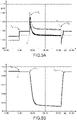
- the inventors have simulated the behavior of a combination of a generator forming the network (or “grid former” according to Anglo-Saxon terminology) and of a synchronous generator.
- Figure 3A represents the voltage delivered (vertical axis) as a function of time (horizontal axis) by the generator forming the network (curve A1) and by the synchronous generator (curve B1).
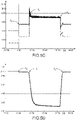
- the Figure 3B represents the active power delivered (vertical axis) as a function of time (horizontal axis) by the generator forming the network (curve A2) and by the synchronous generator (curve B2).
- the Fig. 3C represents the reactive power delivered (vertical axis) as a function of time (horizontal axis) by the generator forming the network (curve A3) and by the synchronous generator (curve B3).
- the 3d figure represents the frequency f delivered (vertical axis) as a function of time (horizontal axis) by generator forming the network (curve A4) and by the synchronous generator (curve B4).
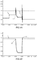
- the inventors have simulated the behavior of an inverter forming the network.
- the figure 4A represents the active power delivered by the inverter (vertical axis) as a function of time (horizontal axis).
- the figure 4B represents the power frequency delivered by the inverter (vertical axis) as a function of time (horizontal axis).
- the Fig. 4C represents the current delivered by the inverter (vertical axis) as a function of time (horizontal axis).
- the 4D figure represents the voltage delivered by the inverter (vertical axis) as a function of time (horizontal axis).
- a fault appears on the network.
- the latter takes the form of a load call of 660 kW ( figure 4A ).
- the adjustment is carried out in such a way as to keep the V/f ratio constant according to the terms of the present invention, and thus ensure the stability of the network.
- the secondary regulation phase begins from time t 2 in order to restore the network to a state imposed by the operator.
- the inventors have simulated the behavior of two inverters capable of forming the network.
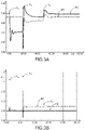
- the figure 5A represents the active power (vertical axis) delivered by each of the inverters as a function of time (horizontal axis).
- the figure 5B represents the power frequency (vertical axis) delivered by each of the inverters as a function of time (horizontal axis).
- the Fig. 5C represents the current delivered (vertical axis) delivered by each of the inverters as a function of time (horizontal axis).
- the figure 5D represents the voltage delivered (vertical axis) delivered by each of the inverters as a function of time (horizontal axis).
- the two inverters again regulate the frequency ( figure 5B ) and voltage ( figure 5D ) so as to keep the V/f ratio constant according to the terms of the present invention, and thus ensure the stability of the network.
- the secondary regulation phase begins from time t 2 in order to restore the network to a state imposed by the operator.
Landscapes
- Engineering & Computer Science (AREA)
- Power Engineering (AREA)
- Supply And Distribution Of Alternating Current (AREA)
- Remote Monitoring And Control Of Power-Distribution Networks (AREA)
Description
- La présente invention concerne un procédé de régulation d'un réseau de distribution électrique. En particulier, la présente invention propose un procédé de régulation d'un réseau de distribution électrique indépendant de la réserve primaire dont il dispose.
- Notamment, la présente invention propose un procédé de régulation permettant d'assurer la stabilité du réseau quel que soit l'état de la réserve primaire.
- Le procédé est particulièrement adapté pour la régulation d'un micro-réseau, notamment un micro-réseau présentant un taux de pénétration d'énergie renouvelable important.
- La stabilité des réseaux de distribution électrique est une préoccupation permanente des exploitants desdits réseaux. Ces derniers sont alors traditionnellement conçus pour répondre à un critère dit « critère N-1 » qui leur permet de supporter la survenance d'un défaut sans incidence majeure sur la stabilité du réseau et ainsi éviter une situation de coupure électrique générale (« Black-out » selon la terminologie Anglo-Saxonne).
- Afin de satisfaire le critère N-1, les réseaux interconnectés mettent en commun leurs sources de production d'énergie électrique et proposent des schémas de fonctionnement permettant de réagir de manière appropriée lorsqu'un défaut survient sur le réseau.
- Il est alors prévu selon ces schémas de délester certaines charges, de démarrer d'autres sources d'énergie telles que des groupes électrogènes, ou des générateurs virtuels synchrones.
- À cet égard, le respect du critère N-1 comprend le dimensionnement d'une réserve primaire d'énergie (« Spinning Reserve » selon la terminologie Anglo-Saxonne) suffisante pour répondre à un évènement donné et de manière immédiate dans le cadre d'une régulation primaire.
- Cette régulation primaire implique notamment un ajustement, par statisme, de la fréquence ou la tension du réseau de distribution électrique afin de répondre à un appel de charge ou compenser un défaut survenant sur le réseau de distribution électrique.
- Une régulation dite secondaire peut alors intervenir ultérieurement afin de rétablir le réseau de distribution électrique dans son état initial.
- La réserve primaire est relativement flexible dès lors qu'elle est mise en œuvre par des sources de production d'énergie prévisibles et stables telles que des groupes électrogènes.
- Toutefois, dès lors que la réserve primaire est insuffisante pour répondre soit à un appel de charge ou à un défaut sur le réseau, une régulation par statisme conduira inéluctablement à un black-out.
- Par ailleurs, le dimensionnement d'une réserve primaire devient compliqué dès lors que les sources de production d'énergie électrique impliquent des sources intermittentes telles que des sources d'énergie renouvelable.
- Cette complication est d'autant plus importante que le réseau de distribution électrique est un micro réseau fonctionnant de manière autonome.
- En outre, les sources intermittentes ne présentent en générale qu'une faible inertie, et réagissent de manière dispersée et non coordonnée lors de la survenance d'un défaut ou d'un appel de charge exacerbant ainsi l'instabilité du réseau. Un tel comportement des sources intermittentes ne permet pas d'assurer la stabilité du réseau.
- Enfin, la régulation par statisme peut générer des variations de flux et ainsi provoquer des dégradations au niveau de tous les équipements assurant le fonctionnement du réseau.
- Il a pu être proposé de conférer aux sources intermittentes un caractère de générateur synchrone, dit générateur synchrone virtuel.
- Toutefois, dans la mesure où il n'existe pas de norme régissant le fonctionnement des générateurs synchrones virtuels permettant à ces derniers d'assurer la stabilité d'un réseau, cette solution n'est pas toujours satisfaisante.
- Un but de la présente invention est de proposer un procédé de contrôle d'un générateur permettant de garantir la stabilité du réseau de distribution électrique.
- Un autre but de la présente invention est de proposer un procédé de contrôle d'un générateur permettant d'augmenter le taux de pénétration des sources d'énergie renouvelable.
- Un autre but de la présente invention est de proposer un procédé de contrôle d'un générateur permettant de garantir la stabilité du réseau également lorsque la réserve primaire est insuffisante.
- Enfin, un autre but de la présente invention est de proposer un procédé de contrôle d'un générateur offrant une protection contre la dégradation des différents équipements, notamment les équipements électrosensibles, assurant le fonctionnement du réseau.
- De l'état de l'art concernant le domaine des procédés de régulation on connait également les documents
EP 2 600 479 A1 ,CN 108808699 ,CN106385054 ,WO 2018/122726 A1 etCN 108631320 . - Les buts de la présente invention sont, au moins en partie, atteints par un procédé de régulation d'un réseau de distribution électrique qui comprend une source électrique dite source principale, parmi une ou plusieurs sources électriques, configurée pour imposer au réseau la tension V et la fréquence f d'une puissance P circulant sur le du réseau et auquel sont connectées une ou plusieurs charges.
- Le procédé comprend, en cas de variation de l'une parmi la fréquence f ou la tension V détectée sur le réseau, lors d'une régulation primaire, une étape d'ajustement, par la source principale, de l'autre parmi la fréquence f et la tension V de manière à conserver le rapport de la tension V sur la fréquence f essentiellement constant.
- Par « essentiellement constant », on entend un rapport pouvant présenter des variations de plus ou moins 5 % autour d'une valeur de consigne.
- Ainsi, selon la présente invention, en réponse à un appel de charge ou à l'apparition d'un défaut sur le réseau, le maintien du rapport V/f permet d'assurer la stabilité du réseau sans considération relative à la réserve primaire.
- Par ailleurs, dans la mesure où cette régulation est indépendante de la réserve primaire, il peut être considéré une contribution plus importante des énergies renouvelables, par exemple 100%.
- En outre, un rapport V/F maintenu essentiellement constant permet de maintenir un flux constant dans les charges, notamment des équipements électrosensibles, et ainsi éviter une usure ou une surchauffe d'un moteur d'une charge.
- Enfin, le procédé selon la présente invention peut être mis en œuvre sur un réseau de distribution électrique déjà existant.
- Selon un mode de mise en œuvre, la source principale comprend un régulateur permettant d'exécuter l'étape d'ajustement.
- Selon un mode de mise en œuvre, le régulateur mesure la fréquence f et la tension V du réseau de distribution, avantageusement, la mesure est effectuée à intervalles de temps réguliers.
- Selon un mode de mise en œuvre, la source principale est intermittente.
- Selon un mode de mise en œuvre, la source principale peut ne pas imposer de puissance, et comprendre par exemple un moteur dont l'arbre n'est pas connecté.
- La source principale peut comprendre un système de stockage d'énergie, par exemple n volant d'inertie, une batterie....
- Selon un mode de mise en œuvre, la source principale est une source d'énergie renouvelable, en particulier la source d'énergie renouvelable comprend au moins une source choisie parmi : une source d'énergie solaire, une source d'énergie éolienne, une source d'énergie.
- Selon un mode de mise en œuvre, la source principale comprend un onduleur doté d'une loi de commande lui conférant un comportement de générateur synchrone de sorte que la source principale forme un générateur synchrone virtuel.
- Selon un mode de mise en œuvre, l'au moins une source comprend également d'autres sources, avantageusement des sources intermittentes, encore plus avantageusement des sources d'énergie renouvelable.
- Selon un mode de mise en œuvre, la régulation primaire est suivie d'une régulation secondaire permettant de restaurer la fréquence f et la tension V du réseau à des valeurs prédéterminées.
- Selon un mode de mise en œuvre, une des sources électrique du réseau de distribution électrique dispose d'une réserve d'énergie primaire, le procédé comprenant, préalablement à l'étape d'ajustement, une étape d'évaluation de la réserve primaire au regard d'un appel de charge ou d'un défaut susceptible de survenir sur le réseau.
- Selon un mode de mise en œuvre, dès lors que la réserve primaire est évaluée comme suffisante pour répondre à un appel de charge ou à un défaut, l'étape d'évaluation comprend également la mise en œuvre d'une régulation basée sur l'injection d'au moins une partie de la réserve primaire sur le réseau de manière à répondre à l'appel de charge ou au défaut.
- L'invention concerne également un programme d'ordinateur, comprenant des instructions qui, lorsqu'il est exécuté par un calculateur, conduisent à mettre en œuvre le procédé de régulation selon l'invention.
- L'invention concerne également une source électrique configurée pour imposer à un réseau la tension V et la fréquence f d'une puissance P circulant sur ledit réseau, et pourvue du programme d'ordinateur selon la présente invention.
- D'autres caractéristiques et avantages apparaîtrons dans la description qui va suivre des modes de mise en œuvre du procédé de régulation d'un réseau de distribution électrique selon l'invention, donnés à titre d'exemples non limitatifs, en référence aux dessins annexés dans lesquels :
- La
figure 1 est une représentation schématique d'un réseau de distribution électrique sur lequel la présente invention est susceptible d'être mise en œuvre ; - La
figure 2 est une représentation en modules fonctionnels d'une source primaire et d'un régulateur susceptible d'être mis en œuvre dans le cadre de la présente invention ; - La
figure 3A représente la tension délivrée (axe vertical) en fonction du temps (axe horizontal) par le générateur formant le réseau (courbe A1) et par le générateur synchrone (courbe B1) dans le cadre d'une première simulation de la présente invention ; - La
figure 3B représente la puissance active délivrée (axe vertical) en fonction du temps (axe horizontal) par le générateur formant le réseau (courbe A2) et par le générateur synchrone (courbe B2) dans le cadre de la première simulation de la présente invention ; - La
figure 3C représente la puissance réactive délivrée (axe vertical) en fonction du temps (axe horizontal) par le générateur formant le réseau (courbe A3) et par le générateur synchrone (courbe B3) dans le cadre de la première simulation de la présente invention ; - La
figure 3D représente la fréquence f délivrée (axe vertical) en fonction du temps (axe horizontal) par le générateur formant le réseau (courbe A4) et par le générateur synchrone (courbe B4) dans le cadre de la première simulation de la présente invention ; - La
figure 4A représente la puissance active (axe vertical) délivrée par un onduleur en fonction du temps (axe horizontal) dans le cadre d'une deuxième simulation de la présente invention ; - La
figure 4B représente la fréquence de puissance (axe vertical) délivrée par un onduleur en fonction du temps (axe horizontal) dans le cadre de la deuxième simulation de la présente invention ; - La
figure 4C représente le courant délivré (axe vertical) délivrée par un onduleur en fonction du temps (axe horizontal) dans le cadre de la deuxième simulation de la présente invention ; - La
figure 4D représente la tension délivrée (axe vertical) délivrée deux onduleurs en fonction du temps (axe horizontal) dans le cadre de la deuxième simulation de la présente invention ; - La
figure 5A représente la puissance active (axe vertical) délivrée par deux onduleurs en fonction du temps (axe horizontal) dans le cadre d'une troisième simulation de la présente invention ; - La
figure 5B représente la fréquence de puissance (axe vertical) délivrée par deux onduleurs en fonction du temps (axe horizontal) dans le cadre de la troisième simulation de la présente invention ; - La
figure 5C représente les courants délivrés (axe vertical) délivrée par deux onduleurs en fonction du temps (axe horizontal) dans le cadre de la troisième simulation de la présente invention ; - La
figure 5D représente les tensions délivrées (axe vertical) délivrée deux onduleurs en fonction du temps (axe horizontal) dans le cadre de la troisième simulation de la présente invention. - La présente invention décrite de manière détaillée ci-dessous met en œuvre un procédé de régulation d'un réseau de distribution électrique pourvu d'une source, dite source principale, parmi une ou plusieurs sources d'énergie, configurée pour imposer au réseau la tension V et la fréquence f d'une puissance P circulant sur le réseau et destinée à être consommée par des charges.
- En particulier, la source principale est adaptée pour maintenir constant le rapport de la tension V et de la fréquence f de la puissance P circulant sur le réseau.
- Par « source électrique », on entend toute source susceptible de délivrer ou non un courant électrique, d'imposer une tension.
- À titre d'exemple, une source électrique peut comprendre, et de manière non limitative, un générateur synchrone, un générateur asynchrone, une source de tension.
- La présente invention, bien que décrite dans le contexte des réseaux de distribution électrique de manière générale, peut avantageusement être mise en œuvre au sein d'un micro-réseau.
- Par « micro-réseau » (« microgrid » selon la terminologie Anglo-Saxonne), on entend un réseau électrique local destiné à produire et distribuer de l'énergie électrique dans des régions isolées et distantes des grands centres de production d'énergie électrique. Les régions isolées sont par exemples des îles, des régions montagneuses, ou encore des zones désertiques. Le principe de micro réseau s'applique également lorsqu'un bâtiment, quartier, campus, ou autre entité connectée à un large réseau de distribution souhaite gérer sa production d'énergie autrement et augmenter sa capacité de résilience.
- Le principal intérêt des micro réseaux est qu'ils fonctionnent de manière autonome (en mode îloté, sans connexion au réseau public), et se trouvent à proximité des zones de consommation (les charges). Ainsi, les pertes inhérentes aux réseaux de distributions longues distances sont limitées.
- Par ailleurs, selon la présente invention, un « réseau de distribution électrique » peut comprendre un réseau de distribution électrique ou un réseau de transport électrique ou encore un réseau de répartition électrique.
- L'invention est maintenant décrite en détails en relation avec les
figures 1, 2 ,3A à 3D ,4A à 4D , et5A à 5D . - La
figure 1 représente un réseau de distribution électrique 10. - Le réseau de distribution électrique comprend une ou plusieurs sources électriques. Parmi l'une ou plusieurs sources électriques figure une source dite source principale 20 qui est configurée pour imposer au réseau la tension V et la fréquence f d'une puissance P circulant (ou distribuée) sur le réseau de distribution électrique 10.
- En d'autres termes, la source principale 20 peut former le réseau.
- La source principale 20 peut comprendre un générateur synchrone, notamment un groupe électrogène.
- De manière alternative, la source principale 20 peut comprendre une source d'énergie intermittente. Plus particulièrement, la source d'énergie intermittente peut comprendre une source d'énergie renouvelable, et par exemple comprendre des panneaux photovoltaïques, des éoliennes, des hydroliennes, des machines thermodynamiques.
- La source d'énergie intermittente peut être pourvue d'un onduleur (« inverter » selon la terminologie Anglo-Saxonne) doté d'une loi de commande conférant à la source d'énergie intermittente un comportement de générateur synchrone de sorte que la source principale forme un générateur synchrone virtuel.
- L'une ou plusieurs sources peut également comprendre d'autres sources, avantageusement des sources intermittentes 21, encore plus avantageusement des sources d'énergie renouvelable. Par exemple, les sources d'énergie renouvelable peuvent comprendre des panneaux photovoltaïques, des éoliennes, des hydroliennes, des machines thermodynamiques.
- De manière complémentaire ou alternative, l'au moins une source peut comprendre une ou plusieurs batteries 22.
- Toujours de manière complémentaire ou alternative, l'une ou plusieurs sources peut comprendre un ou plusieurs générateurs 23, par exemple des générateurs synchrones, des générateurs asynchrones, ou une combinaison des deux.
- Le procédé selon la présente invention comprend une étape de d'ajustement, dans le cadre d'une régulation primaire, qui maintient essentiellement constant le rapport de la tension V sur la fréquence f.
- En particulier, dès lors que la fréquence f de la puissance électrique P circulant sur le réseau varie, l'étape d'ajustement comprend un ajustement de la tension V de manière à maintenir essentiellement constant le rapport de la tension V sur la fréquence f.
- De manière équivalente, une variation de la tension V de la puissance électrique P circulant sur le réseau varie, l'étape d'ajustement comprend un ajustement de la fréquence f de manière à maintenir essentiellement constant le rapport de la tension V sur la fréquence f.
- De telles variations de fréquence et/ou de tension de la puissance P circulant sur le réseau de distribution électrique peuvent intervenir lors d'appels de charge ou lors de l'apparition d'un défaut.
- Cette régulation est mise en œuvre par la source principale qui est en mesure de former le réseau.
- À cet égard, la source principale 20 peut comprendre un régulateur R configuré pour assurer la régulation selon les termes de l'invention.
- En particulier, le régulateur peut mesurer la fréquence f et la tension V de la puissance électrique P.
- De manière particulièrement avantageuse, la mesure est effectuée à intervalles de temps réguliers, par exemple toutes les secondes.
- Cette mesure permet d'établir l'état du réseau et également de détecter la survenance d'un évènement tel qu'un appel de charge ou l'apparition d'un défaut.
- La
figure 2 est une représentation schématique de la mise en œuvre de la régulation selon la présente invention. - En particulier, la
figure 2 représente une source principale 20 connectée à un réseau de distribution électrique 10 distribuant une puissance P à une charge 30. - La source principale 20 est associée à un régulateur pourvu de sous-modules, et notamment un module de régulation de la fréquence 20a, un module de régulation de la tension 20b et un module de contrôle 20c du module de régulation de la fréquence 20a et du module de régulation de la tension 20b.
- Le module de régulation de la fréquence 20a impose à la source principale 20 d'ajuster la fréquence d'une puissance circulant sur le réseau à une fréquence donnée.
- Le module de régulation de la tension 20b impose à la source principale 20 d'ajuster la tension d'une puissance circulant sur le réseau à une tension donnée.
- Le module de contrôle 20c indique au module de fréquence 20a et au module de régulation de tension 20b, respectivement, la fréquence f et la tension V que la source primaire doit imposer au réseau.
- De manière avantageuse, la mesure de la tension V et de la fréquence f de la puissance P circulant sur le réseau sont mesurées par le module de contrôle 20c.
- La régulation ainsi proposée permet de préserver un équilibre entre puissance consommée et puissance produite à tout instant indépendamment de l'état d'une éventuelle réserve primaire.
- La régulation peut également incorporer une modulation de la fréquence et/ou de la tension par statisme si une réserve primaire suffisante est immédiatement disponible pour répondre à un évènement donné.
- La régulation proposée selon la présente invention est également avantageuse dans la mesure où elle ne requiert pas de communication entre les différents équipements, et notamment les sources d'énergies, connectés au réseau.
- La régulation primaire peut être suivie d'une régulation secondaire permettant de restaurer la fréquence f et la tension V du réseau à des valeurs prédéterminées.
- L'invention concerne également un programme d'ordinateur, comprenant des instructions qui, lorsqu'il est exécuté par un calculateur, conduisent à mettre en œuvre le procédé selon la présente invention.
- L'invention concerne également une source d'énergie configurée pour imposer à un réseau la tension V et la fréquence f d'une puissance P circulant sur ledit réseau, et pourvue du programme d'ordinateur selon la présente invention.
- Le procédé selon la présente invention a fait l'objet de différentes simulations.
- Selon un premier exemple, les inventeurs ont simulé le comportement d'une combinaison d'un générateur formant le réseau (ou « grid former » selon la terminologie Anglo-Saxonne) et d'un générateur synchrone.
- À cet égard, les
figures 3A à 3D représentent les résultats relatifs à la simulation numérique de la régulation d'un réseau à la suite d'une chute de la puissance active sur ledit réseau à un instant t=t0. - En particulier, la
figure 3A représente la tension délivrée (axe vertical) en fonction du temps (axe horizontal) par le générateur formant le réseau (courbe A1) et par le générateur synchrone (courbe B1). - La
figure 3B représente la puissance active délivrée (axe vertical) en fonction du temps (axe horizontal) par le générateur formant le réseau (courbe A2) et par le générateur synchrone (courbe B2). - La
figure 3C représente la puissance réactive délivrée (axe vertical) en fonction du temps (axe horizontal) par le générateur formant le réseau (courbe A3) et par le générateur synchrone (courbe B3). - La
figure 3D représente la fréquence f délivrée (axe vertical) en fonction du temps (axe horizontal) par générateur formant le réseau (courbe A4) et par le générateur synchrone (courbe B4). - A t=t0, la tension (courbe A1
figure 3A ) et la puissance réactive (courbe A3figure 3C ) délivrées par le générateur formant le réseau chutent d'environ 10%. A partir de cet instant, le générateur synchrone est mis en route et synchronisé avec le réseau à l'instant t1 = t0+20s (courbes B1, B2, B3, B4). - A l'instant t1, le générateur synchrone ajuste la fréquence f de la puissance électrique qu'il délivre sur le réseau afin de maintenir le rapport V/f à une valeur prédéterminée correspondant au rapport de la tension de consigne et de la fréquence de consigne du réseau. Cet ajustement se déroule lors de la phase de régulation primaire qui s'étend entre l'instant t1 et un instant t2 = t0 + 50s.
- Selon un deuxième exemple, les inventeurs ont simulé le comportement d'un onduleur formant le réseau.
- La
figure 4A représente la puissance active délivrée par l'onduleur (axe vertical) en fonction du temps (axe horizontal). - La
figure 4B représente la fréquence de puissance délivrée par l'onduleur (axe vertical) en fonction du temps (axe horizontal). - La
figure 4C représente le courant délivré par l'onduleur (axe vertical) en fonction du temps (axe horizontal). - La
figure 4D représente la tension délivrée par l'onduleur (axe vertical) en fonction du temps (axe horizontal). - A l'instant t0, un appel de charge 150kW intervient. L'onduleur dispose alors d'une réserve primaire suffisante pour y répondre par statisme.
- À un instant t1=t0+10s, un défaut apparait sur le réseau. Ce dernier se matérialise par un appel de charge de 660 kW (
figure 4A ). La réserve primaire étant dans ce cas de figure insuffisante, l'onduleur ajuste à la fois la fréquence f (figure 4B ) et la tension V (figure 4D ) de la puissance qu'il délivre pendant la phase de régulation primaire qui s'étend entre l'instant t1 et l'instant t2=t0+20s. Durant cette phase, l'ajustement est exécuté de manière à maintenir constant le rapport V/f selon les termes de la présente invention, et ainsi assurer la stabilité du réseau. - La phase de régulation secondaire débute à partir de l'instant t2 afin de rétablir le réseau dans un état imposé par l'exploitant.
- Selon un troisième exemple, les inventeurs ont simulé le comportement de deux onduleurs capables de former le réseau.
- La
figure 5A représente la puissance active (axe vertical) délivrée par chacun des onduleurs en fonction du temps (axe horizontal). - La
figure 5B représente la fréquence de puissance (axe vertical) délivrée par chacun des onduleurs en fonction du temps (axe horizontal). - La
figure 5C représente le courant délivré (axe vertical) délivrée par chacun des onduleurs en fonction du temps (axe horizontal). - La
figure 5D représente la tension délivrée (axe vertical) délivrée par chacun des onduleurs en fonction du temps (axe horizontal). - A l'instant t0, un appel de charge 150kW intervient. Les onduleurs ajustent alors chacun leur fréquence (
figure 5B ) et leur tension (figure 5D ) de manière à conserver le rapport V/f essentiellement constant. Cette première régulation s'étend entre l'instant to et un instant t1 = to + 10s à partir duquel le réseau subit un deuxième appel de charge de 495 kW (figure 5A ). - À cet instant t1= t0+10s, les deux onduleurs régulent à nouveau la fréquence (
figure 5B ) et la tension (figure 5D ) de manière à maintenir constant le rapport V/f selon les termes de la présente invention, et ainsi assurer la stabilité du réseau. - La phase de régulation secondaire débute à partir de l'instant t2 afin de rétablir le réseau dans un état imposé par l'exploitant.
- Ces simulations démontrent que la régulation selon les termes de l'invention peut être mise en œuvre sur des réseaux alimentés par une ou plusieurs sources d'énergie, et notamment un ou plusieurs onduleurs capables de former le réseau.
- Le caractère universel de la méthode proposée rend son application possible dans bon nombre de réseaux de distribution préexistants.
Claims (12)
- Procédé de régulation d'un réseau de distribution électrique (10) qui comprend une source électrique dite source principale (20), parmi une ou plusieurs sources électriques, configurée pour imposer au réseau la tension V et la fréquence f d'une puissance P circulant sur le réseau et auquel sont connectées une ou plusieurs charges,
caractérisé en ce que
le procédé comprend, en cas de variation de l'une parmi la fréquence f ou la tension V détectée sur le réseau, lors d'une régulation primaire, une étape d'ajustement, par la source principale (20), de l'autre parmi la fréquence f et la tension V, de manière à conserver le rapport de la tension V sur la fréquence f constant. - Procédé selon la revendication 1, dans lequel la source principale (20) comprend un régulateur permettant d'exécuter l'étape d'ajustement.
- Procédé selon la revendication 2, dans lequel le régulateur mesure la fréquence f et la tension V du réseau de distribution, les mesures étant effectuées à intervalles de temps réguliers.
- Procédé selon l'une des revendications 1 à 3, dans lequel la source principale (20) est intermittente.
- Procédé selon la revendication 4, dans lequel la source principale (20) est une source d'énergie renouvelable, en particulier la source d'énergie renouvelable comprend au moins une source choisie parmi : une source d'énergie solaire, une source d'énergie éolienne, une source d'énergie.
- Procédé selon la revendication 4 ou 5, dans lequel la source principale (20) comprend un onduleur doté d'une loi de commande lui conférant un comportement de générateur synchrone de sorte que la source principale (20) forme un générateur synchrone virtuel.
- Procédé selon l'une des revendications 1 à 6, dans lequel le réseau de distribution électrique (10) comprend également d'autres sources, avantageusement des sources intermittentes (21), ou des sources d'énergie renouvelable.
- Procédé selon l'une des revendications 1 à 7, dans lequel la régulation primaire est suivie d'une régulation secondaire permettant de restaurer la fréquence f et la tension V du réseau à des valeurs prédéterminées.
- Procédé selon l'une des revendications 1 à 8, dans lequel une des sources électrique du réseau de distribution électrique (10) dispose d'une réserve d'énergie primaire, le procédé comprenant, préalablement à l'étape d'ajustement, une étape d'évaluation de la réserve primaire au regard d'un appel de charge ou d'un défaut susceptible de survenir sur le réseau.
- Procédé selon la revendication 9, dans lequel dès lors que la réserve primaire est évaluée comme suffisante pour répondre à un appel de charge ou à un défaut, l'étape d'évaluation comprend également la mise en œuvre d'une régulation basée sur l'injection d'au moins une partie de la réserve primaire sur le réseau de manière à répondre à l'appel de charge ou au défaut.
- Programme d'ordinateur, comprenant des instructions qui, lorsqu'il est exécuté par un calculateur, conduisent à mettre en œuvre le procédé selon l'une des revendications 1 à 10.
- Source électrique configurée pour imposer à un réseau la tension V et la fréquence f d'une puissance P circulant sur ledit réseau, et pourvue du programme d'ordinateur selon la revendication 11.
Applications Claiming Priority (1)
| Application Number | Priority Date | Filing Date | Title |
|---|---|---|---|
| FR1873570A FR3090916B1 (fr) | 2018-12-20 | 2018-12-20 | Procede de regulation d’un reseau de distribution electrique |
Publications (2)
| Publication Number | Publication Date |
|---|---|
| EP3672011A1 EP3672011A1 (fr) | 2020-06-24 |
| EP3672011B1 true EP3672011B1 (fr) | 2022-10-26 |
Family
ID=67185134
Family Applications (1)
| Application Number | Title | Priority Date | Filing Date |
|---|---|---|---|
| EP19216819.3A Active EP3672011B1 (fr) | 2018-12-20 | 2019-12-17 | Procédé de régulation d'un réseau de distribution électrique |
Country Status (4)
| Country | Link |
|---|---|
| US (1) | US11728652B2 (fr) |
| EP (1) | EP3672011B1 (fr) |
| CN (1) | CN111355248B (fr) |
| FR (1) | FR3090916B1 (fr) |
Family Cites Families (18)
| Publication number | Priority date | Publication date | Assignee | Title |
|---|---|---|---|---|
| US7481069B2 (en) * | 2005-07-28 | 2009-01-27 | Carrier Corporation | Controlling a voltage-to-frequency ratio for a variable speed drive in refrigerant systems |
| US20100138070A1 (en) * | 2009-02-26 | 2010-06-03 | Ronald Beaudoin | System and method for improving power grid stability |
| EP2600479A1 (fr) * | 2011-12-02 | 2013-06-05 | ABB Research Ltd. | Contrôle d'un réseau électrique avec fonctionnement en îlots |
| US9400330B2 (en) * | 2012-10-19 | 2016-07-26 | Schweitzer Engineering Laboratories, Inc. | Manipulation resilient time distribution network |
| US9042141B2 (en) * | 2013-02-07 | 2015-05-26 | Caterpillar Inc. | Control of energy storage system inverter system in a microgrid application |
| CN103345869B (zh) * | 2013-06-25 | 2016-01-06 | 武汉理工大学 | 基于复合能源并网发电的千瓦级船舶能源系统实验平台 |
| US9593672B2 (en) * | 2013-08-07 | 2017-03-14 | Siemens Aktiengesellschaft | Isochronous wind turbine generator capable of stand-alone operation |
| CN103545810B (zh) * | 2013-11-12 | 2015-07-15 | 国家电网公司 | 基于小信号稳定分析的微电网逆变器下垂自动控制方法 |
| CA2886409C (fr) * | 2013-12-06 | 2016-03-22 | Rajiv Kumar Varma | Modulateur de commande multivariable pour installation de production d'energie electrique |
| CN105515007A (zh) * | 2014-10-18 | 2016-04-20 | 杨利 | 电力系统电压频率调节控制器 |
| US9444257B2 (en) * | 2014-12-02 | 2016-09-13 | Osisoft, Llc | Hierarchical control of micro-grids |
| US9960637B2 (en) * | 2015-07-04 | 2018-05-01 | Sunverge Energy, Inc. | Renewable energy integrated storage and generation systems, apparatus, and methods with cloud distributed energy management services |
| CN106385054B (zh) * | 2016-11-22 | 2019-02-15 | 国网辽宁省电力有限公司锦州供电公司 | 分布式光伏逆变器运行控制方法 |
| IT201600131878A1 (it) * | 2016-12-28 | 2018-06-28 | Electro Power Systems Mfg S R L | Sistema di controllo di microreti di produzione e distribuzione di energia elettrica proveniente da più fonti di produzione di tipo diverso, e relativo metodo di controllo |
| CN107273586A (zh) * | 2017-05-25 | 2017-10-20 | 哈尔滨工程大学 | 一种针对太阳能船舶的光伏波动功率低成本抑制方法 |
| US10651654B2 (en) * | 2017-11-07 | 2020-05-12 | State Grid Corporation Of China | Model predictive controller for autonomous hybrid microgrids |
| CN108631320A (zh) * | 2018-06-01 | 2018-10-09 | 三峡大学 | 一种基于前馈鲁棒控制的微电网电压控制方法 |
| CN108808699A (zh) * | 2018-07-10 | 2018-11-13 | 华北电力大学(保定) | 一种适用于双向储能设备的双象限频率特性分析方法 |
-
2018
- 2018-12-20 FR FR1873570A patent/FR3090916B1/fr not_active Expired - Fee Related
-
2019
- 2019-12-17 EP EP19216819.3A patent/EP3672011B1/fr active Active
- 2019-12-18 US US16/719,115 patent/US11728652B2/en active Active
- 2019-12-20 CN CN201911327435.6A patent/CN111355248B/zh active Active
Also Published As
| Publication number | Publication date |
|---|---|
| EP3672011A1 (fr) | 2020-06-24 |
| FR3090916B1 (fr) | 2022-06-03 |
| CN111355248B (zh) | 2025-03-25 |
| US20200203955A1 (en) | 2020-06-25 |
| US11728652B2 (en) | 2023-08-15 |
| CN111355248A (zh) | 2020-06-30 |
| FR3090916A1 (fr) | 2020-06-26 |
Similar Documents
| Publication | Publication Date | Title |
|---|---|---|
| EP3185386B1 (fr) | Procede de controle d'un micro reseau de distribution electrique | |
| EP3208907B1 (fr) | Procede de controle d'un generateur virtuel | |
| Samuelsson et al. | On speed stability | |
| Vournas et al. | Postmortem analysis and data validation in the wake of the 2004 Athens blackout | |
| US10819269B2 (en) | DC integration of photovoltaic and DFIG wind turbine generation with electric storage | |
| Tuckey et al. | Decentralized control of a microgrid | |
| Dozein et al. | Frequency response capabilities of utility-scale battery energy storage systems, with application to the august 2018 separation event in australia | |
| FR3020190A1 (fr) | Procede de controle et regulation d'un reseau electrique | |
| EP3627649B1 (fr) | Procédé de contrôle d'un générateur | |
| EP3672011B1 (fr) | Procédé de régulation d'un réseau de distribution électrique | |
| Bawayan et al. | Mitigating low fault current in microgrids through renewables-battery hybrid units | |
| EP3731398A1 (fr) | Procédé de commande d'un convertisseur dc/ac | |
| Frack et al. | Control-strategy design for frequency control in autonomous smart microgrids | |
| EP4203222B1 (fr) | Procédé de régulation conjointe de la tension dans une branche moyenne tension hta et des branches basse tension bt dont une branche basse tension bt triphasée | |
| CA3183945A1 (fr) | Procede de pilotage de charge et de decharge d'une pluralite de dispositifs de stockage d'energie electrique | |
| Kumar et al. | Dynamic grid support system for mitigation of impact of high penetration solar PV into grid | |
| US11437817B2 (en) | Method and device for driving an electricity production assembly, and associated production assembly | |
| Potamianakis et al. | Aggregation of wind farms in distribution networks | |
| Almeida et al. | Electric vehicles in automatic generation control for systems with large integration of renewables | |
| EP2533391B1 (fr) | Système de gestion multi-sources de générateurs électriques | |
| FR3069110A1 (fr) | Procede de commande d'une pluralite d'accumulateurs | |
| Aktarujjaman et al. | Dynamics of a hydro-wind hybrid isolated power system | |
| FR2999029A1 (fr) | Dispositif et procede de regulation de l'alimentation electrique d'un reseau ayant une source photovoltaique. | |
| Asber et al. | Transient behavior of a distribution network incorporating decentralized generation | |
| EP3800777A1 (fr) | Modification des valeurs de paramètres de la loi de commande d'un générateur |
Legal Events
| Date | Code | Title | Description |
|---|---|---|---|
| PUAI | Public reference made under article 153(3) epc to a published international application that has entered the european phase |
Free format text: ORIGINAL CODE: 0009012 |
|
| STAA | Information on the status of an ep patent application or granted ep patent |
Free format text: STATUS: THE APPLICATION HAS BEEN PUBLISHED |
|
| AK | Designated contracting states |
Kind code of ref document: A1 Designated state(s): AL AT BE BG CH CY CZ DE DK EE ES FI FR GB GR HR HU IE IS IT LI LT LU LV MC MK MT NL NO PL PT RO RS SE SI SK SM TR |
|
| AX | Request for extension of the european patent |
Extension state: BA ME |
|
| STAA | Information on the status of an ep patent application or granted ep patent |
Free format text: STATUS: REQUEST FOR EXAMINATION WAS MADE |
|
| 17P | Request for examination filed |
Effective date: 20201120 |
|
| RBV | Designated contracting states (corrected) |
Designated state(s): AL AT BE BG CH CY CZ DE DK EE ES FI FR GB GR HR HU IE IS IT LI LT LU LV MC MK MT NL NO PL PT RO RS SE SI SK SM TR |
|
| REG | Reference to a national code |
Ref country code: DE Ref legal event code: R079 Ref document number: 602019021065 Country of ref document: DE Free format text: PREVIOUS MAIN CLASS: H02J0003240000 Ipc: H02J0003460000 |
|
| GRAJ | Information related to disapproval of communication of intention to grant by the applicant or resumption of examination proceedings by the epo deleted |
Free format text: ORIGINAL CODE: EPIDOSDIGR1 |
|
| GRAP | Despatch of communication of intention to grant a patent |
Free format text: ORIGINAL CODE: EPIDOSNIGR1 |
|
| GRAP | Despatch of communication of intention to grant a patent |
Free format text: ORIGINAL CODE: EPIDOSNIGR1 |
|
| STAA | Information on the status of an ep patent application or granted ep patent |
Free format text: STATUS: GRANT OF PATENT IS INTENDED |
|
| RIC1 | Information provided on ipc code assigned before grant |
Ipc: H02J 3/48 20060101ALI20220429BHEP Ipc: H02J 3/38 20060101ALI20220429BHEP Ipc: H02J 3/28 20060101ALI20220429BHEP Ipc: H02J 3/24 20060101ALI20220429BHEP Ipc: H02J 3/46 20060101AFI20220429BHEP |
|
| INTG | Intention to grant announced |
Effective date: 20220524 |
|
| GRAS | Grant fee paid |
Free format text: ORIGINAL CODE: EPIDOSNIGR3 |
|
| GRAA | (expected) grant |
Free format text: ORIGINAL CODE: 0009210 |
|
| STAA | Information on the status of an ep patent application or granted ep patent |
Free format text: STATUS: THE PATENT HAS BEEN GRANTED |
|
| AK | Designated contracting states |
Kind code of ref document: B1 Designated state(s): AL AT BE BG CH CY CZ DE DK EE ES FI FR GB GR HR HU IE IS IT LI LT LU LV MC MK MT NL NO PL PT RO RS SE SI SK SM TR |
|
| REG | Reference to a national code |
Ref country code: GB Ref legal event code: FG4D Free format text: NOT ENGLISH |
|
| REG | Reference to a national code |
Ref country code: CH Ref legal event code: EP |
|
| REG | Reference to a national code |
Ref country code: AT Ref legal event code: REF Ref document number: 1527769 Country of ref document: AT Kind code of ref document: T Effective date: 20221115 |
|
| REG | Reference to a national code |
Ref country code: DE Ref legal event code: R096 Ref document number: 602019021065 Country of ref document: DE |
|
| REG | Reference to a national code |
Ref country code: IE Ref legal event code: FG4D Free format text: LANGUAGE OF EP DOCUMENT: FRENCH |
|
| REG | Reference to a national code |
Ref country code: LT Ref legal event code: MG9D |
|
| REG | Reference to a national code |
Ref country code: NL Ref legal event code: MP Effective date: 20221026 |
|
| REG | Reference to a national code |
Ref country code: AT Ref legal event code: MK05 Ref document number: 1527769 Country of ref document: AT Kind code of ref document: T Effective date: 20221026 |
|
| PG25 | Lapsed in a contracting state [announced via postgrant information from national office to epo] |
Ref country code: NL Free format text: LAPSE BECAUSE OF FAILURE TO SUBMIT A TRANSLATION OF THE DESCRIPTION OR TO PAY THE FEE WITHIN THE PRESCRIBED TIME-LIMIT Effective date: 20221026 |
|
| PG25 | Lapsed in a contracting state [announced via postgrant information from national office to epo] |
Ref country code: SE Free format text: LAPSE BECAUSE OF FAILURE TO SUBMIT A TRANSLATION OF THE DESCRIPTION OR TO PAY THE FEE WITHIN THE PRESCRIBED TIME-LIMIT Effective date: 20221026 Ref country code: PT Free format text: LAPSE BECAUSE OF FAILURE TO SUBMIT A TRANSLATION OF THE DESCRIPTION OR TO PAY THE FEE WITHIN THE PRESCRIBED TIME-LIMIT Effective date: 20230227 Ref country code: NO Free format text: LAPSE BECAUSE OF FAILURE TO SUBMIT A TRANSLATION OF THE DESCRIPTION OR TO PAY THE FEE WITHIN THE PRESCRIBED TIME-LIMIT Effective date: 20230126 Ref country code: LT Free format text: LAPSE BECAUSE OF FAILURE TO SUBMIT A TRANSLATION OF THE DESCRIPTION OR TO PAY THE FEE WITHIN THE PRESCRIBED TIME-LIMIT Effective date: 20221026 Ref country code: FI Free format text: LAPSE BECAUSE OF FAILURE TO SUBMIT A TRANSLATION OF THE DESCRIPTION OR TO PAY THE FEE WITHIN THE PRESCRIBED TIME-LIMIT Effective date: 20221026 Ref country code: ES Free format text: LAPSE BECAUSE OF FAILURE TO SUBMIT A TRANSLATION OF THE DESCRIPTION OR TO PAY THE FEE WITHIN THE PRESCRIBED TIME-LIMIT Effective date: 20221026 Ref country code: AT Free format text: LAPSE BECAUSE OF FAILURE TO SUBMIT A TRANSLATION OF THE DESCRIPTION OR TO PAY THE FEE WITHIN THE PRESCRIBED TIME-LIMIT Effective date: 20221026 |
|
| PG25 | Lapsed in a contracting state [announced via postgrant information from national office to epo] |
Ref country code: RS Free format text: LAPSE BECAUSE OF FAILURE TO SUBMIT A TRANSLATION OF THE DESCRIPTION OR TO PAY THE FEE WITHIN THE PRESCRIBED TIME-LIMIT Effective date: 20221026 Ref country code: PL Free format text: LAPSE BECAUSE OF FAILURE TO SUBMIT A TRANSLATION OF THE DESCRIPTION OR TO PAY THE FEE WITHIN THE PRESCRIBED TIME-LIMIT Effective date: 20221026 Ref country code: LV Free format text: LAPSE BECAUSE OF FAILURE TO SUBMIT A TRANSLATION OF THE DESCRIPTION OR TO PAY THE FEE WITHIN THE PRESCRIBED TIME-LIMIT Effective date: 20221026 Ref country code: IS Free format text: LAPSE BECAUSE OF FAILURE TO SUBMIT A TRANSLATION OF THE DESCRIPTION OR TO PAY THE FEE WITHIN THE PRESCRIBED TIME-LIMIT Effective date: 20230226 Ref country code: HR Free format text: LAPSE BECAUSE OF FAILURE TO SUBMIT A TRANSLATION OF THE DESCRIPTION OR TO PAY THE FEE WITHIN THE PRESCRIBED TIME-LIMIT Effective date: 20221026 Ref country code: GR Free format text: LAPSE BECAUSE OF FAILURE TO SUBMIT A TRANSLATION OF THE DESCRIPTION OR TO PAY THE FEE WITHIN THE PRESCRIBED TIME-LIMIT Effective date: 20230127 |
|
| REG | Reference to a national code |
Ref country code: DE Ref legal event code: R097 Ref document number: 602019021065 Country of ref document: DE |
|
| PG25 | Lapsed in a contracting state [announced via postgrant information from national office to epo] |
Ref country code: SM Free format text: LAPSE BECAUSE OF FAILURE TO SUBMIT A TRANSLATION OF THE DESCRIPTION OR TO PAY THE FEE WITHIN THE PRESCRIBED TIME-LIMIT Effective date: 20221026 Ref country code: RO Free format text: LAPSE BECAUSE OF FAILURE TO SUBMIT A TRANSLATION OF THE DESCRIPTION OR TO PAY THE FEE WITHIN THE PRESCRIBED TIME-LIMIT Effective date: 20221026 Ref country code: EE Free format text: LAPSE BECAUSE OF FAILURE TO SUBMIT A TRANSLATION OF THE DESCRIPTION OR TO PAY THE FEE WITHIN THE PRESCRIBED TIME-LIMIT Effective date: 20221026 Ref country code: DK Free format text: LAPSE BECAUSE OF FAILURE TO SUBMIT A TRANSLATION OF THE DESCRIPTION OR TO PAY THE FEE WITHIN THE PRESCRIBED TIME-LIMIT Effective date: 20221026 Ref country code: CZ Free format text: LAPSE BECAUSE OF FAILURE TO SUBMIT A TRANSLATION OF THE DESCRIPTION OR TO PAY THE FEE WITHIN THE PRESCRIBED TIME-LIMIT Effective date: 20221026 |
|
| REG | Reference to a national code |
Ref country code: CH Ref legal event code: PL |
|
| REG | Reference to a national code |
Ref country code: BE Ref legal event code: MM Effective date: 20221231 |
|
| PG25 | Lapsed in a contracting state [announced via postgrant information from national office to epo] |
Ref country code: SK Free format text: LAPSE BECAUSE OF FAILURE TO SUBMIT A TRANSLATION OF THE DESCRIPTION OR TO PAY THE FEE WITHIN THE PRESCRIBED TIME-LIMIT Effective date: 20221026 Ref country code: LU Free format text: LAPSE BECAUSE OF NON-PAYMENT OF DUE FEES Effective date: 20221217 Ref country code: AL Free format text: LAPSE BECAUSE OF FAILURE TO SUBMIT A TRANSLATION OF THE DESCRIPTION OR TO PAY THE FEE WITHIN THE PRESCRIBED TIME-LIMIT Effective date: 20221026 |
|
| PLBE | No opposition filed within time limit |
Free format text: ORIGINAL CODE: 0009261 |
|
| STAA | Information on the status of an ep patent application or granted ep patent |
Free format text: STATUS: NO OPPOSITION FILED WITHIN TIME LIMIT |
|
| 26N | No opposition filed |
Effective date: 20230727 |
|
| PG25 | Lapsed in a contracting state [announced via postgrant information from national office to epo] |
Ref country code: LI Free format text: LAPSE BECAUSE OF NON-PAYMENT OF DUE FEES Effective date: 20221231 Ref country code: IE Free format text: LAPSE BECAUSE OF NON-PAYMENT OF DUE FEES Effective date: 20221217 Ref country code: CH Free format text: LAPSE BECAUSE OF NON-PAYMENT OF DUE FEES Effective date: 20221231 |
|
| PG25 | Lapsed in a contracting state [announced via postgrant information from national office to epo] |
Ref country code: SI Free format text: LAPSE BECAUSE OF FAILURE TO SUBMIT A TRANSLATION OF THE DESCRIPTION OR TO PAY THE FEE WITHIN THE PRESCRIBED TIME-LIMIT Effective date: 20221026 Ref country code: BE Free format text: LAPSE BECAUSE OF NON-PAYMENT OF DUE FEES Effective date: 20221231 |
|
| PG25 | Lapsed in a contracting state [announced via postgrant information from national office to epo] |
Ref country code: HU Free format text: LAPSE BECAUSE OF FAILURE TO SUBMIT A TRANSLATION OF THE DESCRIPTION OR TO PAY THE FEE WITHIN THE PRESCRIBED TIME-LIMIT; INVALID AB INITIO Effective date: 20191217 |
|
| PG25 | Lapsed in a contracting state [announced via postgrant information from national office to epo] |
Ref country code: CY Free format text: LAPSE BECAUSE OF FAILURE TO SUBMIT A TRANSLATION OF THE DESCRIPTION OR TO PAY THE FEE WITHIN THE PRESCRIBED TIME-LIMIT Effective date: 20221026 |
|
| PG25 | Lapsed in a contracting state [announced via postgrant information from national office to epo] |
Ref country code: MK Free format text: LAPSE BECAUSE OF FAILURE TO SUBMIT A TRANSLATION OF THE DESCRIPTION OR TO PAY THE FEE WITHIN THE PRESCRIBED TIME-LIMIT Effective date: 20221026 Ref country code: IT Free format text: LAPSE BECAUSE OF FAILURE TO SUBMIT A TRANSLATION OF THE DESCRIPTION OR TO PAY THE FEE WITHIN THE PRESCRIBED TIME-LIMIT Effective date: 20221026 |
|
| PG25 | Lapsed in a contracting state [announced via postgrant information from national office to epo] |
Ref country code: MC Free format text: LAPSE BECAUSE OF FAILURE TO SUBMIT A TRANSLATION OF THE DESCRIPTION OR TO PAY THE FEE WITHIN THE PRESCRIBED TIME-LIMIT Effective date: 20221026 |
|
| PG25 | Lapsed in a contracting state [announced via postgrant information from national office to epo] |
Ref country code: MC Free format text: LAPSE BECAUSE OF FAILURE TO SUBMIT A TRANSLATION OF THE DESCRIPTION OR TO PAY THE FEE WITHIN THE PRESCRIBED TIME-LIMIT Effective date: 20221026 |
|
| PG25 | Lapsed in a contracting state [announced via postgrant information from national office to epo] |
Ref country code: BG Free format text: LAPSE BECAUSE OF FAILURE TO SUBMIT A TRANSLATION OF THE DESCRIPTION OR TO PAY THE FEE WITHIN THE PRESCRIBED TIME-LIMIT Effective date: 20221026 |
|
| PG25 | Lapsed in a contracting state [announced via postgrant information from national office to epo] |
Ref country code: MT Free format text: LAPSE BECAUSE OF FAILURE TO SUBMIT A TRANSLATION OF THE DESCRIPTION OR TO PAY THE FEE WITHIN THE PRESCRIBED TIME-LIMIT Effective date: 20221026 |
|
| PG25 | Lapsed in a contracting state [announced via postgrant information from national office to epo] |
Ref country code: TR Free format text: LAPSE BECAUSE OF FAILURE TO SUBMIT A TRANSLATION OF THE DESCRIPTION OR TO PAY THE FEE WITHIN THE PRESCRIBED TIME-LIMIT Effective date: 20221026 |
|
| PGFP | Annual fee paid to national office [announced via postgrant information from national office to epo] |
Ref country code: GB Payment date: 20251223 Year of fee payment: 7 |
|
| PGFP | Annual fee paid to national office [announced via postgrant information from national office to epo] |
Ref country code: FR Payment date: 20251230 Year of fee payment: 7 |
|
| PGFP | Annual fee paid to national office [announced via postgrant information from national office to epo] |
Ref country code: DE Payment date: 20251229 Year of fee payment: 7 |