EP3208907B1 - Steuerungsverfahren eines virtuellen generators - Google Patents
Steuerungsverfahren eines virtuellen generators Download PDFInfo
- Publication number
- EP3208907B1 EP3208907B1 EP17155581.6A EP17155581A EP3208907B1 EP 3208907 B1 EP3208907 B1 EP 3208907B1 EP 17155581 A EP17155581 A EP 17155581A EP 3208907 B1 EP3208907 B1 EP 3208907B1
- Authority
- EP
- European Patent Office
- Prior art keywords
- power
- voltage
- generator
- virtual generator
- accumulation system
- Prior art date
- Legal status (The legal status is an assumption and is not a legal conclusion. Google has not performed a legal analysis and makes no representation as to the accuracy of the status listed.)
- Active
Links
Images

Classifications
-
- G—PHYSICS
- G05—CONTROLLING; REGULATING
- G05F—SYSTEMS FOR REGULATING ELECTRIC OR MAGNETIC VARIABLES
- G05F1/00—Automatic systems in which deviations of an electric quantity from one or more predetermined values are detected at the output of the system and fed back to a device within the system to restore the detected quantity to its predetermined value or values, i.e. retroactive systems
- G05F1/66—Regulating electric power
-
- H—ELECTRICITY
- H02—GENERATION; CONVERSION OR DISTRIBUTION OF ELECTRIC POWER
- H02J—ELECTRIC POWER NETWORKS; CIRCUIT ARRANGEMENTS OR SYSTEMS FOR SUPPLYING OR DISTRIBUTING ELECTRIC POWER; SYSTEMS FOR STORING ELECTRIC ENERGY
- H02J3/00—Circuit arrangements for AC mains or AC distribution networks
- H02J3/18—Arrangements for adjusting, eliminating or compensating reactive power in networks
- H02J3/1807—Arrangements for adjusting, eliminating or compensating reactive power in networks using series compensators, e.g. thyristor-controlled series capacitors [TCSC]
- H02J3/1814—Arrangements for adjusting, eliminating or compensating reactive power in networks using series compensators, e.g. thyristor-controlled series capacitors [TCSC] having reactive elements actively controlled by bridge converters, e.g. unified power flow controllers [UPFC] or controlled series voltage compensators
-
- H—ELECTRICITY
- H02—GENERATION; CONVERSION OR DISTRIBUTION OF ELECTRIC POWER
- H02J—ELECTRIC POWER NETWORKS; CIRCUIT ARRANGEMENTS OR SYSTEMS FOR SUPPLYING OR DISTRIBUTING ELECTRIC POWER; SYSTEMS FOR STORING ELECTRIC ENERGY
- H02J3/00—Circuit arrangements for AC mains or AC distribution networks
- H02J3/18—Arrangements for adjusting, eliminating or compensating reactive power in networks
- H02J3/1821—Arrangements for adjusting, eliminating or compensating reactive power in networks using shunt compensators
-
- H—ELECTRICITY
- H02—GENERATION; CONVERSION OR DISTRIBUTION OF ELECTRIC POWER
- H02J—ELECTRIC POWER NETWORKS; CIRCUIT ARRANGEMENTS OR SYSTEMS FOR SUPPLYING OR DISTRIBUTING ELECTRIC POWER; SYSTEMS FOR STORING ELECTRIC ENERGY
- H02J3/00—Circuit arrangements for AC mains or AC distribution networks
- H02J3/38—Arrangements for feeding a single network from two or more generators or sources in parallel; Arrangements for feeding already energised networks from additional generators or sources in parallel
- H02J3/381—Dispersed generators
-
- H—ELECTRICITY
- H02—GENERATION; CONVERSION OR DISTRIBUTION OF ELECTRIC POWER
- H02J—ELECTRIC POWER NETWORKS; CIRCUIT ARRANGEMENTS OR SYSTEMS FOR SUPPLYING OR DISTRIBUTING ELECTRIC POWER; SYSTEMS FOR STORING ELECTRIC ENERGY
- H02J4/00—Circuit arrangements for mains or distribution networks not specified as AC or DC; Circuit arrangements for mains or distribution networks combining AC and DC sections or sub-networks
- H02J4/20—Networks integrating separated AC and DC power sections
- H02J4/25—Networks integrating separated AC and DC power sections for transfer of electric power between AC and DC networks, e.g. for supplying the DC section within a load from an AC mains system
-
- G—PHYSICS
- G05—CONTROLLING; REGULATING
- G05B—CONTROL OR REGULATING SYSTEMS IN GENERAL; FUNCTIONAL ELEMENTS OF SUCH SYSTEMS; MONITORING OR TESTING ARRANGEMENTS FOR SUCH SYSTEMS OR ELEMENTS
- G05B2219/00—Program-control systems
- G05B2219/20—Pc systems
- G05B2219/26—Pc applications
- G05B2219/2619—Wind turbines
-
- H—ELECTRICITY
- H02—GENERATION; CONVERSION OR DISTRIBUTION OF ELECTRIC POWER
- H02J—ELECTRIC POWER NETWORKS; CIRCUIT ARRANGEMENTS OR SYSTEMS FOR SUPPLYING OR DISTRIBUTING ELECTRIC POWER; SYSTEMS FOR STORING ELECTRIC ENERGY
- H02J2101/00—Supply or distribution of decentralised, dispersed or local electric power generation
- H02J2101/10—Dispersed power generation using fossil fuels, e.g. diesel generators
-
- H—ELECTRICITY
- H02—GENERATION; CONVERSION OR DISTRIBUTION OF ELECTRIC POWER
- H02J—ELECTRIC POWER NETWORKS; CIRCUIT ARRANGEMENTS OR SYSTEMS FOR SUPPLYING OR DISTRIBUTING ELECTRIC POWER; SYSTEMS FOR STORING ELECTRIC ENERGY
- H02J2101/00—Supply or distribution of decentralised, dispersed or local electric power generation
- H02J2101/20—Dispersed power generation using renewable energy sources
- H02J2101/22—Solar energy
- H02J2101/24—Photovoltaics
-
- H—ELECTRICITY
- H02—GENERATION; CONVERSION OR DISTRIBUTION OF ELECTRIC POWER
- H02J—ELECTRIC POWER NETWORKS; CIRCUIT ARRANGEMENTS OR SYSTEMS FOR SUPPLYING OR DISTRIBUTING ELECTRIC POWER; SYSTEMS FOR STORING ELECTRIC ENERGY
- H02J2101/00—Supply or distribution of decentralised, dispersed or local electric power generation
- H02J2101/20—Dispersed power generation using renewable energy sources
- H02J2101/28—Wind energy
-
- H—ELECTRICITY
- H02—GENERATION; CONVERSION OR DISTRIBUTION OF ELECTRIC POWER
- H02J—ELECTRIC POWER NETWORKS; CIRCUIT ARRANGEMENTS OR SYSTEMS FOR SUPPLYING OR DISTRIBUTING ELECTRIC POWER; SYSTEMS FOR STORING ELECTRIC ENERGY
- H02J2105/00—Networks for supplying or distributing electric power characterised by their spatial reach or by the load
- H02J2105/10—Local stationary networks having a local or delimited stationary reach
-
- Y—GENERAL TAGGING OF NEW TECHNOLOGICAL DEVELOPMENTS; GENERAL TAGGING OF CROSS-SECTIONAL TECHNOLOGIES SPANNING OVER SEVERAL SECTIONS OF THE IPC; TECHNICAL SUBJECTS COVERED BY FORMER USPC CROSS-REFERENCE ART COLLECTIONS [XRACs] AND DIGESTS
- Y02—TECHNOLOGIES OR APPLICATIONS FOR MITIGATION OR ADAPTATION AGAINST CLIMATE CHANGE
- Y02E—REDUCTION OF GREENHOUSE GAS [GHG] EMISSIONS, RELATED TO ENERGY GENERATION, TRANSMISSION OR DISTRIBUTION
- Y02E10/00—Energy generation through renewable energy sources
- Y02E10/50—Photovoltaic [PV] energy
- Y02E10/56—Power conversion systems, e.g. maximum power point trackers
-
- Y—GENERAL TAGGING OF NEW TECHNOLOGICAL DEVELOPMENTS; GENERAL TAGGING OF CROSS-SECTIONAL TECHNOLOGIES SPANNING OVER SEVERAL SECTIONS OF THE IPC; TECHNICAL SUBJECTS COVERED BY FORMER USPC CROSS-REFERENCE ART COLLECTIONS [XRACs] AND DIGESTS
- Y02—TECHNOLOGIES OR APPLICATIONS FOR MITIGATION OR ADAPTATION AGAINST CLIMATE CHANGE
- Y02E—REDUCTION OF GREENHOUSE GAS [GHG] EMISSIONS, RELATED TO ENERGY GENERATION, TRANSMISSION OR DISTRIBUTION
- Y02E40/00—Technologies for an efficient electrical power generation, transmission or distribution
- Y02E40/10—Flexible AC transmission systems [FACTS]
-
- Y—GENERAL TAGGING OF NEW TECHNOLOGICAL DEVELOPMENTS; GENERAL TAGGING OF CROSS-SECTIONAL TECHNOLOGIES SPANNING OVER SEVERAL SECTIONS OF THE IPC; TECHNICAL SUBJECTS COVERED BY FORMER USPC CROSS-REFERENCE ART COLLECTIONS [XRACs] AND DIGESTS
- Y02—TECHNOLOGIES OR APPLICATIONS FOR MITIGATION OR ADAPTATION AGAINST CLIMATE CHANGE
- Y02P—CLIMATE CHANGE MITIGATION TECHNOLOGIES IN THE PRODUCTION OR PROCESSING OF GOODS
- Y02P80/00—Climate change mitigation technologies for sector-wide applications
- Y02P80/10—Efficient use of energy, e.g. using compressed air or pressurized fluid as energy carrier
- Y02P80/14—District level solutions, i.e. local energy networks
Definitions
- the present invention relates to the field of micro power generation and distribution networks. More particularly, the invention relates to a control method of a virtual generator, and a virtual generator for reproducing the operation of a generator.
- a microgrid (Anglo-Saxon terminology) is typically a local electrical grid for the generation and distribution of electrical energy in remote and isolated areas of major power generation centers. Isolated areas are, for example, islands, mountainous regions, or desert areas.
- the micro-network principle also applies when a building, district, campus, or other entity connected to a large distribution network wishes to manage its energy production otherwise and increase its resilience capacity.
- micro networks operate autonomously (in island mode, without connection to the public network), and are close to the consumption areas (charges). Thus, the losses inherent in long distance distribution networks are limited.
- the energy autonomy of the micro-grid is generally ensured by sources of electrical energy of different types among which the generators occupy an important place (we speak in this case of a source of synchronous energy). Indeed, from an economic point of view, a generator represents a low initial investment, and provides electricity production sufficiently flexible to absorb peak consumption at peak hours. However, their operation requires large amounts of diesel, which therefore increases the energy bill, but also increases air pollution.
- a virtual generator generally comprises a power generation system, such as photovoltaic panels, and an inverter. Photovoltaic panels then produce electrical power by generating a continuous voltage and current. Said DC voltage and current are then converted by the inverter into alternating voltage and current.
- the inverter is generally controlled according to a control law so as to emulate the behavior of a synchronous generator with droop ("Droop" according to the terminology Anglo-Saxon), hence the name of virtual generator. It is thus possible to electrically connect in parallel synchronous generators and virtual generators.
- Droop synchronous generator with droop
- this solution has a cost that is not compatible with the savings desired when implementing a micro network.
- the electric power delivered by the renewable energy source is subject to climatic fluctuations, thereby generating a fluctuating electrical power.
- sunshine can vary very rapidly, and in minute proportions, generating peaks and troughs of electrical power produced by a photovoltaic panel.
- These fluctuations are a source of instability that the micro network can not tolerate.
- a conventional inverter powered by electric power for example by a renewable energy source
- Anglo-Saxon terminology we say it is “Grid-Tie”.
- Grid-Forming a system forming the network.
- the share of renewable energy sources can not exceed, by convention, a value between 20 and 30% (we are talking about the penetration rate of renewable energy sources) so that at least one means of production of non-intermittent electrical power, for example a generator, is running continuously.
- This limitation gives the micro-network the necessary stability, but in fact limits the achievable savings.
- An object of the invention is then to propose a method for controlling a virtual generator and a virtual generator for improving the match between the electrical power produced by the virtual generator and the electrical power actually consumed by the load.
- Another object of the invention is, also, to propose a method for controlling a virtual generator and a virtual generator for reducing (smoothing) the effect of the electrical power fluctuations of the renewable energy source on the microphone. network.
- Another object of the invention is also to provide a method for controlling a virtual generator and a virtual generator for increasing the penetration rate of intermittent renewable energy sources without, however, degrading the stability of the micro-network.
- the aims of the invention are, at least in part, achieved by a method of controlling a virtual generator comprising at least one renewable energy source, an accumulation system comprising a reserve of power and / or of energy, an inverter and a control law, the virtual generator delivering to a micro-array an active electrical power P / reactive Q of voltage V and current I, said voltage V and current I having a frequency f, said active electrical power P / responsive Q controlling by statism, respectively, the frequency f and the voltage V rms V voltage, the method being remarkable in that it comprises a control of the virtual generator by the control law for it to perform an adjustment the active power P / reactive delivered to the micro network, said adjustment being adapted to compensate for a variation of the active / reactive power consumed by the micro-network, the accumulator system ion applies a voltage V ref continues to the first terminals of the renewable energy source so that the renewable energy source delivers a power P sr , said power P sr is likely to have power fluctuations, the system
- the compensation of the variation of the active electrical power P / reactive Q is executed so as to balance the active electrical power P / reactive Q delivered by the virtual generator with the active electrical power P / reactive Q consumed by the micro-network.
- the implementation of said compensation is enabled by the presence of the accumulation system and its reserve power and / or energy.
- the reserve of power and / or energy can supply active power P / reactive Q to the micro-network during a power call.
- the accumulation system is also adapted to accumulate active P / reactive power Q produced by the renewable energy source and not consumed by the micro network.
- the method according to the invention makes it possible to reproduce the inertia of a generator set, thus conferring the necessary stability for the active power supply P / reactive Q of the micro-array.
- the control law makes it possible to balance the active P / reactive power Q delivered and consumed, respectively, by the virtual generator and the micro-network.
- the control law comprises the differential equations (the electromechanical equations) governing the operation of a generator, and among others the mechanical differential equation modeling the dynamics of a rotor of said generator.
- the control law according to the invention therefore requires the virtual generator to behave like a generator.
- the virtual generator including the renewable energy source, and the accumulation system adapts to the needs of the micro network without the latter is affected.
- the compensation of the variation of the active power P / reactive Q consumed by the micro-array also induces an adjustment, respectively, of the frequency f of the voltage V, and of the effective voltage V rms of the voltage V by droop. ("Droop" according to Anglo-Saxon terminology).
- the accumulation system can also absorb (store) electrical power when it is not consumed by the micro network. Thus, peaks of fluctuations in the electrical power produced by the source renewable energy are absorbed by the accumulation system. Thus, the electrical power fluctuations of the renewable energy source are compensated within the virtual generator by the accumulation system. As a result, the effect of the power fluctuations of the renewable energy source on the micro-array is reduced.
- control law is adapted to confer on the virtual generator, advantageously via the inverter, the possibility of forming the network.
- control law is adapted to connect the virtual generator in parallel with generating sets.
- the voltage V ref continuously applied to the first output terminals is the result of conversion of a voltage V PS continuous across a storage system, a DC / DC converter, the system of storage and the DC / DC converter is included in the accumulation system.
- the power delivered by the renewable energy source is dependent on the continuous voltage V ref applied by the accumulation system.
- the accumulation system can adjust the power P sr produced by the renewable energy source according to the needs of the micro network. In other words, the accumulation system can limit the electric power produced by the renewable energy source when the consumption of the network decreases.
- the voltage V ref is determined as a function of a power P sr setpoint that must deliver the renewable energy source, the voltage is determined by the accumulation system.
- the power delivered by the renewable energy source is dependent on the continuous voltage V ref applied by the accumulation system.
- the accumulation system can adjust the power P sr produced by the renewable energy source according to the needs of the micro network. In other words, the accumulation system can limit the electric power produced by the renewable energy source when the consumption of the micro network decreases.
- the accumulation system can also limit the power delivered by the renewable energy source when said system is not more able to absorb a surplus of electrical power likely to be produced by the renewable energy source and consumed by the micro-network.
- the state of charge of the accumulation system exceeds a given threshold, it is able to adjust the voltage V ref so that the power P sr produced by the renewable energy source is completely consumed by the network microphone.
- the voltage V ref is determined by a scanning, for example by steps, in voltage of the first output terminals, and by simultaneously measuring the intensity of the current produced by the renewable energy source and of said voltage.
- the voltage sweep produces power variations of the power delivered by the renewable energy source
- the accumulation system is controlled to compensate for said variations during said sweep.
- the method comprises a step of measuring a state of charge of the accumulation system.
- the voltage V ref is adjusted so that, when the accumulation system has a state of charge greater than or equal to a predetermined maximum load threshold SoC max , the power P sr is completely consumed by the network microphone.
- the state of charge of the SoC accumulation system is maintained at a value greater than a minimum state of charge SoC min .
- a power P acc is delivered by the accumulation system to the micro-grid, via the inverter, since said micro-network must consume a surplus of power P on the renewable energy source n ' is not able to provide.
- the virtual generator according to the invention makes it possible to reproduce the inertia of a generator set, thus conferring the necessary stability for the active power supply P / reactive Q of the micro-array.
- the control law makes it possible to balance the active P / reactive power Q delivered and consumed, respectively, by the virtual generator and the micro-network.
- the control law comprises the differential equations (the electromechanical equations) governing the operation of a generator, and among others the mechanical differential equation modeling the dynamics of a rotor of said generator.
- the control law according to the invention therefore requires the virtual generator to behave like a generator.
- the virtual generator including the renewable energy source, and the accumulation system adapts to the needs of the micro network without the latter is affected.
- the compensation of the variation of the active power P / reactive Q consumed by the micro-array also induces an adjustment, respectively, of the frequency f and of the effective voltage V rms by droop ("Droop" according to the English terminology). Saxon).
- control law is adapted to confer on the virtual generator, advantageously via the inverter, the possibility of forming the network.
- control law is adapted to connect the virtual generator in parallel with generating sets.
- control law is adapted to determine the voltage V ref as a function of a power P sr setpoint that must deliver the renewable energy source via the accumulation system.
- the accumulation system can adjust the power P sr produced by the renewable energy source according to the needs of the micro network. In other words, the accumulation system can limit the electric power produced by the renewable energy source when the consumption of the network decreases.
- the accumulation system is adapted to perform a voltage sweep of the first output terminals, and to simultaneously measure the intensity of the current produced by the renewable energy source and said voltage.
- control law is adapted to require the accumulation system to compensate for fluctuations in the power delivered by the renewable energy source.
- the renewable energy source comprises photovoltaic panels.
- the renewable energy source comprises wind turbines.
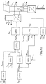
- the figures 1a and 1b represent a virtual generator 1 according to the invention.
- a virtual generator 1 behaving like a generator.
- the generating set delivers, to a micro-array, an active electrical power P / reactive Q of voltage V and current I, said voltage V and current I having a frequency f.
- the active power P / reactive Q controls by droop, respectively, the frequency f and the effective voltage V rms of the voltage V.
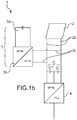
- the droop control of the frequency f by the active power P delivered by the generator is illustrated in FIG. figure 3 .
- the frequency f varies according to a linear function of the active power P, relative (in%), delivered by the generator.
- the linear function is characterized by a slope D bearing the name of droop ("Droop" according to the Anglo-Saxon terminology).
- the frequency f of the voltage V and the current I delivered by the generator set is a function of the rotational speed of the engine shaft of the generator set.
- the speed of rotation of the shaft adapts to also adjust the frequency f of the voltage and current associated with the power. active electric motor P.
- This regulation of the rotational speed of the motor shaft is executed by a speed control block (the "Governor" block).
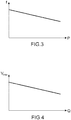
- the droop control of the effective voltage V rms of the voltage V by the reactive power Q delivered by the generator is illustrated in FIG. figure 4 .
- the effective voltage V rms varies according to a linear function of the reactive power Q, relative (in%), delivered by the generator.
- the linear function is characterized by a slope D bearing the name of droop ("Droop" according to the Anglo-Saxon terminology).
- the effective voltage V rms is a function of the reactive power Q delivered by the generator.
- a generator generally comprises a rotor driven in rotation in a stator and an automatic voltage regulator ("AVR” or “Automatic Voltage Regulator” in Anglo-Saxon terminology) acting on the rotor windings of the rotor.
- the automatic voltage regulator thus applies a voltage on the rotor windings as a function of the effective voltage V rms (of the voltage V) delivered by the stator (by the generator) on the micro-array.
- the voltage / reactive power droop control Q allows the genset to adapt the effective voltage V rms it delivers according to the reactive power Q that it provides.
- the rotor of a generator is generally driven in rotation, by a shaft of a heat engine (for example a diesel engine), inside a stator.
- a heat engine for example a diesel engine
- the generator is able to form the network.
- the generator can impose the voltage V and the frequency f to an electrical network.
- the rotor of the generator set has a rotational kinetic energy which is a function of the mass and the rotational speed of its rotor, which can be transferred to the micro-array in the form of an active power P.
- the generator set can respond to a power demand from the micro-network (an additional power consumption demand) by taking kinetic energy from the shaft and transferring it to the micro-array.
- the generating set then adjusts by statism the frequency f of the active power P delivered.
- the generator set is capable of respond to a variation in demand for active power, we say that the generator has inertia. Equivalently, the generator can respond to a change in demand for reactive power from the micro network.
- the generator sets, by droop, the effective voltage V rms of the voltage V.
- the capacity of the generator to respond to a variation in power consumption active P / reactive Q by the micro network can be associated with the concept of primary reserve or spinning reserve ("Spinning Reserve" in Anglo-Saxon terminology).
- the concepts of inertia and primary reserve of a generating set can be modeled in differential equations.
- the virtual generator 1 is controlled by a control law which integrates the differential equations for modeling the operation (the behavior) of the generator.
- the virtual generator 1 is configured to emulate the behavior of a synchronous generator, and more particularly that of a generator.
- the configuration of the virtual generator 1 then comprises the determination of the differential equations governing the operation of the synchronous generator and the development of a computer program (or an algorithm) based on said differential equations.
- the configuration is known to those skilled in the art, and is described in document [2].
- the virtual generator 1 is controlled by the control law so that it executes an adjustment of the active power P / reactive Q delivered to the micro-array, said adjustment being adapted to compensate a variation of the active / reactive power. consumed by the micro network.
- the compensation of the variation of the active / reactive electrical power is executed so as to balance the active electrical power P / reactive Q delivered by the virtual generator 1 with the active electrical power P / reactive Q consumed by the micro-network.
- the virtual generator 1 comprises a renewable energy source 2, a power and / or energy accumulation system 3, an inverter 4, and the control law.
- accumulation system 3 refers to the system of accumulation of power and / or energy 3.
- a current and a voltage delivered by the inverter 4 or a current and a voltage delivered by the virtual generator 1 will have the same meaning.
- the renewable energy source 2 can be subject to climatic hazards, and therefore be an unstable source of energy, we call it an intermittent source of renewable energy.
- the renewable energy source 2 may comprise photovoltaic panels, wind turbines, tidal turbines, thermodynamic machines.
- the renewable energy source 2 comprises first output terminals 2a capable of delivering a continuous current and voltage.
- the renewable energy source 2 generally produces a certain power P sr , delivered by its first output terminals 2a, as a function of the voltage V ref applied to said first output terminals 2a.
- P sr the power delivered by its first output terminals 2a
- V ref the voltage applied to said first output terminals 2a.
- photovoltaic panels produce a power (according to the vertical axis P sr vertical) bell-shaped according to the voltage (along the axis V horizontal ref ) applied to the first output terminals 2a.
- the photovoltaic panel can supply the power P sr1 (point A of the figure 2a ), while it can supply the power P srmax when the voltage V ref is equal to V refmax (point B of the figure 2a ).
- the accumulation system 3 comprises second output terminals 3c capable of also delivering a continuous current and voltage.
- the accumulation system 3 may comprise a storage system 3a and a DC / DC converter 3b (a DC / DC converter converts a DC voltage into another DC voltage).
- the storage system 3a may comprise at least one electrochemical battery, a flywheel, a capacitor (or super capacitor).
- supercapacitor we mean a capacitor of a particular technique which makes it possible to obtain a power density and an energy density intermediate between the batteries and the conventional electrolytic capacitors.
- a super capacitor may include a power density in the range of 1000 to 5000 W / Kg, and an energy density in the range of 4 to 6 Wh / Kg.
- the storage system 3a is adapted to deliver a continuous voltage V PS to the DC / DC converter 3b which converts it into another continuous voltage V ref delivered by the second output terminals 3c.
- the first terminals 2a and the second output terminals 3c are electrically connected, for example in parallel.
- the accumulation system 3 applies a voltage V ref to the first output terminals 2a of the renewable energy source 2, so that the renewable energy source 2 delivers a power P sr .
- the DC / DC converter 3b can be controlled by a first control card controlled by the control law.
- the block 200 can be adapted to provide the DC / DC converter 3b with a signal so that said converter 3b applies the voltage V ref to be applied to the first terminals of the renewable energy source 2.
- the inverter 4 can, in turn, be controlled by a second control card also controlled by the control law. Alternatively, the DC / DC converter 3b and the inverter 4 can be controlled by the same control card.
- the first 2a and the second 3c output terminals are connected to the input of the inverter 4.
- the inverter 4 is adapted to convert the continuous current and voltage, produced by the renewable energy source 2 and / or the accumulation system 3, into an alternating current and voltage before injecting them on the micro-array.
- the control law may advantageously be an algorithm implemented in the control card or cards.
- the first control card and the second control card can communicate with each other.
- the communication between the first control card and the second control card makes it possible in particular to exchange information between said control cards.
- the state of charge of the accumulation system 3 we can mention: the currents, voltages, and powers measured at the first 2a and second 3c terminals.
- the control law is also adapted to measure the voltage, the current and the frequency of said voltage and current delivered to the micro-array.
- the control law is adapted to control the renewable power and the accumulation power provided, respectively, by the renewable energy source 2 and the accumulation system 3.
- the inverter 4 delivers to the micro-network a power corresponding to the powers provided by the renewable energy source 2 and the accumulation system 3.
- the accumulation power can be a negative power, namely a power consumed by the accumulation system 3, or a positive power, namely a power delivered by said system 3.
- the accumulation power is positive, for example when the accumulation system 3 delivers power to the inverter 4, intended to be delivered to the micro-array.
- the accumulation power is negative, for example, when the accumulation system 3 recharges by consuming renewable power.
- the law of order imposes permanently a balance between the renewable and accumulation powers and the power delivered by the inverter 4 to the micro network. In other words, the power budget must be balanced.
- control law of the inverter 4 requires that the sum of the renewable and accumulation powers is equal to the power delivered by the inverter 4 to the micro-grid (we insist that the power delivered by the inverter 4 in the micro network is actually consumed by the micro network).
- the control law for example via the block 100, requires the inverter 4 to deliver an alternating current of intensity I abc .
- the reference value of the current I abc can be determined by the block 100 as a function of the voltage V abc delivered by the inverter 4 and measured at its output (V abcms ).
- V abcms the output of the inverter 4
- the inverter 4 reproduces the current I abc of a generator generating a voltage V abc , and responding to the differential equations modeling said generator.
- control law of the inverter 4 is also adapted, according to techniques known to those skilled in the art, to confer on the virtual generator 1 the possibility of forming the network ("Grid Forming" according to the Anglo-Saxon terminology).
- the virtual generator 1 may be alone to supply electrical power to the micro-network as a generator would.
- the virtual generator 1 has a control by frequency droop f / active power P.
- the control by frequency droop f / active power P is a characteristic of a synchronous generator, such as a generator.
- a generator generally comprises a driven shaft, by a diesel engine, in angular rotation whose frequency corresponds to the frequency f of the current and voltage produced by said group.
- the frequency of the shaft follows a frequency control f / active power P according to a law presented to the figure 3 .
- the frequency f / active power control P enables the generator to adapt the frequency f of the signal it delivers as a function of the electrical power P that it supplies.
- the frequency f of the current and of the voltage delivered by said virtual generator 1 depends on Grid code specifications according to Anglo-Saxon terminology.
- the frequency f can be between 48 and 52 Hz, or between 49.5 and 50.5 Hz, or between 58 and 62 Hz, or between 59.5 and 60.5 Hz.
- the virtual generator 1 also has an effective voltage droop control V rms / reactive power Q.
- the control by voltage droop V rms / reactive power Q is a characteristic of a synchronous generator, such as a generator.
- a generator generally comprises a rotor driven in rotation in a stator and an automatic voltage regulator ("AVR” or “Automatic Voltage Regulator” according to the Anglo-Saxon terminology) acting on the rotor windings of the rotor.
- AVR automatic voltage regulator
- the automatic voltage regulator thus applies a voltage on the rotor as a function of a voltage of the electrical signal (and therefore of the power) delivered by the stator (by the generator) on the network.
- the effective voltage V rms of the electrical signal delivered by the generator follows a control by droop V rms / reactive power Q according to a law presented to the figure 4 .
- the control voltage Rms effective voltage rms / reactive power Q allows the genset to adapt the effective voltage V rms of the voltage it delivers according to the reactive power Q that it provides.
- the voltage delivered by said virtual generator 1 depends on the specifications of the micro-network ("Grid code" according to the Anglo-Saxon terminology).
- the control by frequency droop f / active power P or voltage / reactive power Q may be included in the control law of the virtual generator 1 according to techniques known to those skilled in the art.
- the document [3] presents a method for controlling an inverter according to a control by frequency droop f / active power P or effective voltage V rms / reactive power Q. More particularly, the control of the inverter according to a frequency droop f / active power P or effective voltage V rms / reactive power Q may be included in the block 100.
- the virtual generator 1 may comprise, in the case of a three-level inverter 4, two capacitors C + and C - connected together in series to form a equivalent capacitor C.
- the terminals of the equivalent capacitor C are electrically connected, for example in parallel to the first output terminals 2a of the renewable energy source 2 (and therefore, also electrically connected in parallel to the second output terminals 3c of the source of accumulation of power and / or energy 3).
- the control law for example block 300, in this particular case of a three-level inverter 4, is adapted to balance the voltages V DC + and V DC- measured across the terminals, respectively, of the two capacitors C + and C - in order to guarantee an undistorted sinusoidal shape of the current and of the voltage delivered by the inverter 4 to the micro-array.
- the invention is however not limited to the use of a three-level inverter.
- the accumulation system 3 comprises the storage system 3a and the DC / DC converter 3b.
- the second output terminals 3c are the output terminals of the DC / DC converter 3b.
- the DC / DC converter 3b imposes the voltage V ref at the first output terminals 2a of the renewable energy source 2.
- the voltage V ref is the result of the conversion, by the converter 3b, of a DC voltage at storage system terminals 3a.
- the value of the voltage V ref is, however, a set point imposed on the block 200 of the control law slaving the DC / DC converter.
- the power delivered by the renewable energy source 2 is likely to have fluctuations.
- fluctuations we mean rapid variations, for example on time scales of less than 100 ms, or even less than 10 ms, of low amplitude with respect to the quantity considered (in this case the power), for example less than 5% of said size.
- the power fluctuations may, for example, be due to variations in sunshine.
- the power fluctuations delivered by the renewable energy source 2 are accessible by measuring the intensity I pv of the electrical signal produced by the renewable energy source 2.
- the accumulation system 3 is advantageously enslaved by the law. to compensate for the fluctuations of the power delivered by the renewable energy source 2 to the input terminals of the inverter 4.
- the current and of the voltage delivered by the inverter 4 to the mains are free of fluctuations. In other words, they are stable.
- the control law makes it possible to regulate the power of the renewable energy source 2.
- the value of the voltage V ref continues applied by the DC / DC converter 3b to the first output terminals 2a of the Renewable energy source 2 is a set point imposed by block 210 of the control law.
- the set point imposed by the control law may have the objective of controlling the renewable energy source 2 to deliver either a maximum power or a saturation power, the saturation power being less than the maximum power that the source of power. renewable energy 2 can deliver.
- the power delivered by photovoltaic panels, for a given sunlight is dependent on the voltage applied at their output terminals (the first terminals).
- the control law can initially determine the voltage V ref to be applied to the first output terminals 2a of the photovoltaic panel so that the latter provides either all the power it is capable of producing, namely P srmax ( point B of the figure 2a ) is a power Psri less than a predetermined power (Point A of the figure 2a ).
- P srmax point B of the figure 2a
- Psri a power Psri less than a predetermined power
- the block 210 of the control law commands the DC / DC converter 3b to perform a voltage sweep of the first output terminals 2a of the renewable energy source. 2.
- the current I pv and the voltage V pv delivered by the renewable energy source 2 are measured by the block 220 so that the power P sr delivered by said source is known.
- the voltage sweep V ref is executed in successive increments, in the direction of the increasing powers, for example, until the renewable energy source 2 delivers the desired power (the power delivered by the renewable energy source 2 is nevertheless limited to a power P srmax ).
- the voltage sweep can be executed in less than 10 seconds, for example 5 seconds.
- the accumulation system 3 compensates for the variation of the power delivered by the renewable energy source 2 so that there is always a balance between the power consumed by the micro-network and the power delivered by the virtual generator 1.
- the power compensation is also controlled by the control law, so as to constantly ensure the balance between power consumed and power produced.
- the block 260 from known technical data of the renewable energy source (for example the power curves of photovoltaic panels as a function of the insolation and the temperature), it is possible to estimate the power maximum that the renewable energy source can deliver and communicate it to block 210.
- known technical data of the renewable energy source for example the power curves of photovoltaic panels as a function of the insolation and the temperature
- the control law can also be adapted to limit the state of charge of the accumulation system 3 to a state of charge ("SoC” or "State of Charge” in Anglo-Saxon terminology) maximum SoC max . Indeed, in order not to damage the accumulation system 3, it is preferable that its state of charge does not exceed, for example, 100% load or 95% load. Thus, as long as the state of charge is less than SoC max , the accumulation system 3 can store, at least in part, any excess power delivered by the renewable energy source 2 and not consumed by the micro-network. The accumulation system 3 then provides a negative power. Conversely, when the accumulation system 3 is in a state of charge, at least equal to the maximum state of charge SoC max , the accumulation system 3 can no longer store any surplus power delivered by the renewable energy source 2.
- SoC state of charge
- SoC max state of charge
- the block 240 of the control law can continuously estimate the state of charge SoC PSest of the accumulation system 3.
- the estimation of the state of charge can, for example, be obtained by measuring the voltage Vps measured at the terminals of the storage system 3a.
- Block 230 thus dynamically provides the reference value P srsatmax saturating maximum power that can be provided by the renewable energy source 2 when the state of charge of the accumulation system 3 exceeds SoC max .
- the block 230 communicates the reference value P srsatmax to block 210 (the value P srsatmax is also the maximum power value that the micro-network can consume. ).
- the reference value of the voltage V ref determined by the block 210 is then adapted so that the power delivered by the renewable energy source 2 is less than or equal to P srsatmax .
- the block 230 of the control law can impose on the renewable energy source 2 to limit the power it delivers to a power P srsatmax .
- the power P srsatmax being entirely consumed by the micro network.
- the control law makes it possible to determine the voltage V ref to be applied to the first terminals so that all the power delivered by the renewable energy source 2 is entirely consumed by the micro-network.
- Block 250 of the control law is also adapted to ensure a minimum state of charge, SoC min , of the accumulation system 3 so as to ensure proper operation of the virtual generator 1.
- the control law can limit the active power P delivered, P meca , by the inverter 4, so as to divert part of the power delivered by the renewable energy source 2 to the accumulation system 3 so as to restore a sufficient state of charge of this last. This amounts to acting (limiting) the virtual engine torque of the virtual generator 1, in order to limit the power produced by the virtual generator 1 to the micro-network.
- the nominal state of charge SoC nom can be relative to a power to be delivered to the micro network during the start phase, a duration T, of a generator also connected to the micro-network.
- the nominal state of charge, SoC name of the accumulation system 3 can be defined as the maximum active power that can deliver the generator during the time T when it is in full speed.
- SoC Name Generator Since the state of charge of the storage system broke down the nominal charging state SoC Name Generator can be ordered to start. This sequence thus makes it possible to ensure a continuity of the distribution of the current and the voltage and this in a stable manner.
- the control law is adapted to detect any decrease in power output (power deficit) by the renewable energy source 2, and require the accumulation system 3 to compensate for the power deficit.
- the control law detects for example the power deficit by measuring the current I pv at the first output terminals 2a.
- the generator set may be ordered to start as soon as the power available in the accumulation system drops below a threshold load state SoC s .
- control law permanently determines the state of charge SoC of the accumulation system 3 by measuring the voltage V PS at the output terminals of the storage system 3a.
- control law regulates the voltage V ref so as to ensure a balance between the power consumed by the micro-network and the power supplied by the virtual generator 1.
- the control law requires the renewable energy source 2 to deliver all the power it can produce by adjusting the voltage V ref .
- SoC max the control law of the accumulation system 3 to adjust the voltage V ref so that the power supplied by the renewable energy source 2 is completely consumed by the network microphone.
- the invention also allows the inverter, even when saturated in power, to operate in parallel with other power sources and thus keep the micro network stable.
- This result is achieved by saturating the virtual motor torque of the virtual generator 1 so that the maximum virtual mechanical power that can be delivered by the inverter is always less than a maximum electrical power.
- Said maximum power being a characteristic associated with the maximum current that can be delivered by an inverter without risk of being damaged.
- the virtual generator 1 having the stability of a generator. More particularly, the virtual generator 1 according to the invention makes it possible to reduce the impacts of the power fluctuations of the renewable energy source on the micro-network.
- the virtual generator 1 reacts as a generator. It adjusts, in a first time, the frequency f of the current and the voltage it delivers at a lower frequency f to respond to the power demand by drawing power from the power reserve of the accumulation system 3
- This possibility of responding to the power demand of the micro-network confers on the virtual generator 1 the inertia of a generator.
- the inertia of the virtual generator 1, according to the invention is governed by the differential equations of the control law and the power accumulation system 3.
- a virtual generator 1 without an accumulation system 3 does not have inertia, and therefore can not respond to a call for power from the micro network.
- the primary reserve of the virtual generator 1 can respond favorably to an increase in power consumption by the micro network.
- the operating flexibility thus conferred on the virtual generator 1 opens the way to an increase in the penetration rate of renewable energy sources.
- the virtual generator 1 when the renewable energy source substantially decreases or stops its production of electrical power, the virtual generator 1 according to the invention has the power necessary to supply the network microphone during the startup phase of the generator.
- the virtual generator 1 is subject to the control law making it possible to continuously detect the fluctuations in electric power produced by the renewable energy source.
- the control law then enslaves the accumulation system so that it also delivers electrical power during a fluctuation dip of the power produced from the renewable energy source.
- the compensation of the fluctuations by the accumulation system makes it possible to confer on the control method the inertia observed in a synchronous generator such as a generator, we also speak of the stability of the energy production system based on at least a renewable energy source.
Landscapes
- Engineering & Computer Science (AREA)
- Power Engineering (AREA)
- Physics & Mathematics (AREA)
- Electromagnetism (AREA)
- General Physics & Mathematics (AREA)
- Radar, Positioning & Navigation (AREA)
- Automation & Control Theory (AREA)
- Supply And Distribution Of Alternating Current (AREA)
- Control Of Eletrric Generators (AREA)
- Charge And Discharge Circuits For Batteries Or The Like (AREA)
Claims (19)
- Verfahren zum Regeln eines virtuellen Generators (1), umfassend zumindest eine erneuerbare Energiequelle (2), ein Akkumulationssystem (3) mit einer Leistungs- und/oder Energiereserve, einen Wechselrichter (4) und ein Regelungsgesetz, wobei der virtuelle Generator (1) einem Mikronetz eine Wirkleistung P/Blindleistung Q aus Spannung V und Strom I bereitstellt, wobei die Spannung V und der Strom I eine Frequenz f aufweisen, wobei die Wirkleistung P/Blindleistung Q die Frequenz f und die Effektivspannung Vrms der Spannung V jeweils durch Statik regeln,
wobei das Verfahren dadurch gekennzeichnet ist, dass es eine Regelung des virtuellen Generators (1) durch das Regelungsgesetz umfasst, so dass er eine Anpassung der dem Mikronetz bereitgestellten Wirkleistung P/Blindleistung Q durchführt, wobei die Anpassung dazu ausgelegt ist, eine Änderung der von dem Mikronetz aufgenommenen Wirkleistung/Blindleistung zu kompensieren, wobei das Akkumulationssystem (3) eine Gleichspannung Vref an erste Anschlussklemmen (2a) der erneuerbaren Energiequelle (2) anlegt, so dass die erneuerbare Energiequelle (2) eine Leistung Psr bereitstellt, wobei die Leistung Psr Leistungsschwankungen aufweisen kann, wobei das Akkumulationssystem (3) dazu geregelt wird, die Schwankungen zu kompensieren. - Verfahren nach Anspruch 1, wobei das Regelungsgesetz dazu ausgelegt ist, dem virtuellen Generator (1) vorteilhaft über den Wechselrichter (4) die Möglichkeit zu bieten, das Netz zu bilden.
- Verfahren nach Anspruch 1 oder 2, wobei das Regelungsgesetz dazu ausgelegt ist, den virtuellen Generator (1) mit Stromgeneratoren parallel zu schalten.
- Verfahren nach einem der Ansprüche 1 bis 3, wobei die an die ersten Ausgangsklemmen (2a) angelegte Gleichspannung Vref das Ergebnis der Umwandlung einer Gleichspannung VPS an den Anschlussklemmen eines Speichersystems über einen DC/DC-Wandler ist, wobei das Speichersystem und der DC/DC-Wandler in dem Akkumulationssystem (3) enthalten sind.
- Verfahren nach einem der Ansprüche 1 bis 4, wobei die Spannung Vref in Abhängigkeit von einer Sollleistung Psr bestimmt wird, welche die erneuerbare Energiequelle (2) bereitstellen soll, wobei die Spannung von dem Akkumulationssystem (3) vorgegeben wird.
- Verfahren nach einem der Ansprüche 1 bis 5, wobei die Spannung Vref durch beispielsweise schrittweises Abtasten der Spannung der ersten Ausgangsklemmen (2a) und durch gleichzeitiges Messen der Stromstärke des von der erneuerbaren Energiequelle (2) erzeugten Stroms und der Spannung bestimmt wird.
- Verfahren nach Anspruch 6, wobei die Spannungsabtastung Leistungsänderungen der von der erneuerbaren Energiequelle (2) bereitgestellten Leistung erzeugt, wobei das Akkumulationssystem (3) dazu geregelt wird, die Änderungen während der Abtastung zu kompensieren.
- Verfahren nach einem der Ansprüche 1 bis 7, umfassend einen Schritt des Messens eines Ladezustands des Akkumulationssystems (3).
- Verfahren nach einem der Ansprüche 1 bis 8, wobei die Spannung Vref so angepasst wird, dass die Leistung Psr von dem Mikronetz integral aufgenommen wird, wenn das Akkumulationssystem (3) einen Ladezustand höher oder gleich einem vorbestimmten maximalen Ladeschwellwert SoCmax aufweist.
- Verfahren nach einem der Ansprüche 1 bis 9, wobei der Ladezustand des Akkumulationssystems (3) auf einem Wert gehalten wird, der höher als ein minimaler Ladezustand SoCmin ist.
- Verfahren nach einem der Ansprüche 1 bis 10, wobei dem Mikronetz von dem Akkumulationssystem (3) eine Leistung Pacc über den Wechselrichter (4) bereitgestellt wird, wenn das Mikronetz eine Überleistung Psur aufnehmen soll, welche die erneuerbare Energiequelle (2) nicht aufbringen kann.
- Virtueller Generator (1), der dazu ausgelegt ist, einem Mikronetz eine Wirkleistung P/Blindleistung Q mit einer der Spannung der Frequenz f und der Effektivspannung Vrms bereitzustellen, enthaltend:- eine erneuerbare Energiequelle (2);- ein Akkumulationssystem (3), das eine Leistungs- und/oder Energiereserve umfasst;- einen Wechselrichter (4);- ein Regelungsgesetz;wobei das Regelungsgesetz dazu ausgelegt ist, den virtuellen Generator (1) so zu regeln, dass der virtuelle Generator (1) dem Mikronetz eine Wirkleistung P/Blindleistung Q aus Spannung V und Strom I liefert, wobei die Spannung V und der Strom I eine Frequenz f aufweisen, wobei die Wirkleistung P/Blindleistung Q die Frequenz f und der Effektivspannung Vrms der Spannung V jeweils durch Statik regeln,
wobei der virtuelle Generator (1) dadurch gekennzeichnet ist, dass er eine Anpassung der dem Mikronetz bereitgestellten Wirkleistung P/Blindleistung Q durchführt, wenn eine Änderung der von dem Mikronetz aufgenommenen Wirkleistung/Blindleistung auftritt, wobei die Anpassung dazu ausgelegt ist, eine Änderung der aufgenommenen Wirkleistung/Blindleistung zu kompensieren, wobei das Akkumulationssystem (3) ein Speichersystem und einen DC/DC-Wandler enthält, wobei der DC/DC-Wandler die Ausgangsklemmen des Speichersystems mit ersten Ausgangsklemmen (2a) der erneuerbaren Energiequelle (2) verbindet und dazu ausgelegt ist, den ersten Ausgangsklemmen (2a) eine Spannung Vref je nach durch das Regelungsgesetz vorgegebenem Sollwert ausgehend von einer den Ausgangsklemmen des Speichersystems bereitgestellten Gleichspannung VPS bereitzustellen. - Virtueller Generator (1) nach Anspruch 12, wobei das Regelungsgesetz dazu ausgelegt ist, dem virtuellen Generator (1) vorteilhaft über den Wechselrichter (4) die Möglichkeit zu bieten, das Netz zu bilden.
- Virtueller Generator (1) nach Anspruch 12 oder 13, wobei das Regelungsgesetz dazu ausgelegt ist, den virtuellen Generator (1) mit Stromgeneratoren parallel zu schalten.
- Virtueller Generator (1) nach Anspruch 14, wobei das Regelungsgesetz dazu ausgelegt ist, die Spannung Vref in Abhängigkeit von einer Sollleistung Psr zu bestimmen, welche die erneuerbare Energiequelle (2) über das Akkumulationssystem (3) bereitstellen soll.
- Virtueller Generator (1) nach Anspruch 15, wobei das Akkumulationssystem (3) dazu ausgelegt ist, eine Spannungsabtastung der ersten Ausgangsklemmen (2a) durchzuführen und gleichzeitig die Stromstärke des von der erneuerbaren Energiequelle (2) erzeugten Stroms und die Spannung zu messen.
- Virtueller Generator (1) nach einem der Ansprüche 12 bis 16, wobei das Regelungsgesetz dazu ausgelegt ist, dem Akkumulationssystem (3) vorzugeben, Schwankungen der von der erneuerbaren Energiequelle (2) bereitgestellten Leistung zu kompensieren.
- Virtueller Generator (1) nach einem der Ansprüche 12 bis 17, wobei die erneuerbare Energiequelle (2) Photovoltaikpaneele enthält.
- Virtueller Generator (1) nach einem der Ansprüche 12 bis 17, wobei die erneuerbare Energiequelle (2) Windkraftanlagen enthält.
Applications Claiming Priority (1)
| Application Number | Priority Date | Filing Date | Title |
|---|---|---|---|
| FR1651248A FR3047850A1 (fr) | 2016-02-16 | 2016-02-16 | Procede de controle d'un generateur virtuel |
Publications (2)
| Publication Number | Publication Date |
|---|---|
| EP3208907A1 EP3208907A1 (de) | 2017-08-23 |
| EP3208907B1 true EP3208907B1 (de) | 2018-09-05 |
Family
ID=56101576
Family Applications (1)
| Application Number | Title | Priority Date | Filing Date |
|---|---|---|---|
| EP17155581.6A Active EP3208907B1 (de) | 2016-02-16 | 2017-02-10 | Steuerungsverfahren eines virtuellen generators |
Country Status (4)
| Country | Link |
|---|---|
| US (1) | US10452091B2 (de) |
| EP (1) | EP3208907B1 (de) |
| CN (1) | CN107086597B (de) |
| FR (1) | FR3047850A1 (de) |
Cited By (1)
| Publication number | Priority date | Publication date | Assignee | Title |
|---|---|---|---|---|
| EP3836336A1 (de) | 2019-12-10 | 2021-06-16 | Wobben Properties GmbH | Vorrichtung und verfahren zur winkelstabilisierung einer virtuellen synchronmaschine |
Families Citing this family (16)
| Publication number | Priority date | Publication date | Assignee | Title |
|---|---|---|---|---|
| US10461577B2 (en) * | 2017-08-23 | 2019-10-29 | Schneider Electric It Corporation | Inverter paralleling control system and method |
| EP3487027B1 (de) | 2017-11-21 | 2022-04-27 | Schneider Electric Industries SAS | Verfahren zur steuerung eines mikronetzes |
| US10658845B2 (en) * | 2017-12-11 | 2020-05-19 | Ge Energy Power Conversion Technology Limited | Method and system for droop control of power systems |
| CN107947192B (zh) * | 2017-12-15 | 2022-03-04 | 西安理工大学 | 一种下垂控制型孤岛微电网的无功优化配置方法 |
| WO2019210920A1 (en) | 2018-05-03 | 2019-11-07 | Vestas Wind Systems A/S | Integrated hybrid power plants for off-grid systems |
| CN112106288B (zh) * | 2018-05-15 | 2023-11-24 | 三菱电机株式会社 | 电力变换装置以及电力变换系统 |
| FR3086117B1 (fr) | 2018-09-18 | 2020-12-11 | Schneider Electric Ind Sas | Procede de controle d'un generateur |
| CN109409012B (zh) * | 2018-11-30 | 2023-02-28 | 国网青海省电力公司 | 机网耦合背景下光伏虚拟逆变器多机并联稳定性检测方法 |
| CN109713678B (zh) * | 2019-02-12 | 2022-08-30 | 易事特集团股份有限公司 | 微网电压控制方法和系统 |
| CN109980659A (zh) * | 2019-03-18 | 2019-07-05 | 上海电力学院 | 一种基于新型虚拟同步发电机的逆变器控制方法及系统 |
| FR3095559A1 (fr) | 2019-04-25 | 2020-10-30 | Schneider Electric Industries Sas | Procédé de commande d’un convertisseur dc/ac |
| FR3101739B1 (fr) | 2019-10-02 | 2025-03-14 | Schneider Electric Ind Sas | Modification des valeurs de paramètres de la loi de commande d’un générateur |
| CN116195179B (zh) | 2020-08-06 | 2026-03-03 | 维斯塔斯风力系统集团公司 | 用于降低风力涡轮发电机中高扭矩水平和扭矩梯度的方法 |
| JP7536120B2 (ja) * | 2021-01-15 | 2024-08-19 | 三菱電機株式会社 | 電力変換装置 |
| CN114362336B (zh) * | 2021-12-20 | 2024-04-02 | 合肥同智机电控制技术有限公司 | 能量回收利用控制装置及控制方法 |
| CN115833266B (zh) * | 2023-02-14 | 2023-04-21 | 中国科学院电工研究所 | 新能源电力系统中跟网型变流器集群聚合控制方法 |
Family Cites Families (6)
| Publication number | Priority date | Publication date | Assignee | Title |
|---|---|---|---|---|
| CN102157956B (zh) * | 2011-03-01 | 2014-04-16 | 国网电力科学研究院 | 基于虚拟阻抗的逆变器并联运行方法 |
| EP2856602B1 (de) * | 2012-06-05 | 2020-08-19 | ABB Power Grids Switzerland AG | Energieversorgunssystem und betriebsverfahren |
| CN103560546B (zh) * | 2013-11-11 | 2015-07-01 | 东南大学 | 一种计及储能荷电状态的改进下垂控制方法 |
| CN104578857B (zh) * | 2015-01-12 | 2017-07-28 | 阳光电源股份有限公司 | 光伏发电系统的控制方法、控制装置及光伏发电系统 |
| CN105186554B (zh) * | 2015-08-14 | 2017-09-29 | 许继集团有限公司 | 具有转动惯量和阻尼自趋优的虚拟同步发电机方法 |
| CN105305491A (zh) * | 2015-11-03 | 2016-02-03 | 国家电网公司 | 一种基于虚拟同步发电机的光伏电源控制策略 |
-
2016
- 2016-02-16 FR FR1651248A patent/FR3047850A1/fr not_active Ceased
-
2017
- 2017-01-06 US US15/400,262 patent/US10452091B2/en active Active
- 2017-02-10 EP EP17155581.6A patent/EP3208907B1/de active Active
- 2017-02-14 CN CN201710078076.XA patent/CN107086597B/zh active Active
Cited By (1)
| Publication number | Priority date | Publication date | Assignee | Title |
|---|---|---|---|---|
| EP3836336A1 (de) | 2019-12-10 | 2021-06-16 | Wobben Properties GmbH | Vorrichtung und verfahren zur winkelstabilisierung einer virtuellen synchronmaschine |
Also Published As
| Publication number | Publication date |
|---|---|
| US10452091B2 (en) | 2019-10-22 |
| EP3208907A1 (de) | 2017-08-23 |
| CN107086597A (zh) | 2017-08-22 |
| CN107086597B (zh) | 2021-12-17 |
| US20170235322A1 (en) | 2017-08-17 |
| FR3047850A1 (fr) | 2017-08-18 |
Similar Documents
| Publication | Publication Date | Title |
|---|---|---|
| EP3208907B1 (de) | Steuerungsverfahren eines virtuellen generators | |
| EP3185386B1 (de) | Kontrollverfahren eines elektrischen mikroverteilungsnetzes | |
| JP5582831B2 (ja) | 太陽光発電システム | |
| US10819269B2 (en) | DC integration of photovoltaic and DFIG wind turbine generation with electric storage | |
| WO2013024709A1 (ja) | 発電制御装置および複合型自立発電システム | |
| EP2901381A1 (de) | Verfahren zur bestimmung einer vorhersage der stromversorgung durch eine anlage zur stromversorgung | |
| EP3255594A1 (de) | Steuerverfahren zur erzeugung elektrischer energie network produktion und verteilung elektrischer energie | |
| CN115769454A (zh) | 混合动力发电厂快速频率响应 | |
| JP2003317808A (ja) | ナトリウム−硫黄電池の充放電制御方法、並びに電力貯蔵及び補償装置 | |
| US12146470B2 (en) | Method for charging an energy storage system using a wind turbine | |
| Federici et al. | Investigation on battery and fuel cell electric vehicle-to-grid potential for microgrid frequency regulation | |
| FR3049370A1 (fr) | Procede d'optimisation de la consommation de la puissance produite par une source d'electricite renouvelable | |
| CN113273048B (zh) | 用于借助能量产生设备为交流电压网络提供调节功率的方法 | |
| EP2772983B1 (de) | Vorrichtung zur Energiespeicherung, und entsprechendes Verwaltungsverfahren | |
| FR3098663A1 (fr) | Architecture de transfert de l’énergie électrique régénérée dans un aéronef et procédé de transfert de l’énergie électrique régénérée dans une telle architecture | |
| EP3672011B1 (de) | Regulierverfahren eines stromverteilungsnetzes | |
| Kinjyo et al. | Autonomous power system control by decentralized controllable loads | |
| FR3129541A1 (fr) | Dispositif de fourniture d’électricité du type à dispositif d’électronique de puissance adapté à contribuer à l’inertie d’un système électrique | |
| WO2019147887A1 (en) | Wind turbina with electric strorage | |
| FR2999029A1 (fr) | Dispositif et procede de regulation de l'alimentation electrique d'un reseau ayant une source photovoltaique. | |
| JP7427557B2 (ja) | 充電制御装置、充電制御方法、および、充電制御プログラム | |
| Jadhav et al. | Electric Vehicle For Frequency Regulation Of Microgrid | |
| FR3137805A1 (fr) | Dispositif de fourniture d’électricité adapté à maintenir l’inertie d’un système électrique | |
| Jose et al. | A grid integrated wind energy conversion system with fuzzy based maximum power extraction for plug-in electric vehicle | |
| FR3151717A1 (fr) | Procédé de contrôle d’un système formant source d’énergie électrique, dispositif de contrôle et programme d’ordinateur correspondants |
Legal Events
| Date | Code | Title | Description |
|---|---|---|---|
| PUAI | Public reference made under article 153(3) epc to a published international application that has entered the european phase |
Free format text: ORIGINAL CODE: 0009012 |
|
| STAA | Information on the status of an ep patent application or granted ep patent |
Free format text: STATUS: THE APPLICATION HAS BEEN PUBLISHED |
|
| AK | Designated contracting states |
Kind code of ref document: A1 Designated state(s): AL AT BE BG CH CY CZ DE DK EE ES FI FR GB GR HR HU IE IS IT LI LT LU LV MC MK MT NL NO PL PT RO RS SE SI SK SM TR |
|
| AX | Request for extension of the european patent |
Extension state: BA ME |
|
| STAA | Information on the status of an ep patent application or granted ep patent |
Free format text: STATUS: REQUEST FOR EXAMINATION WAS MADE |
|
| 17P | Request for examination filed |
Effective date: 20171205 |
|
| RBV | Designated contracting states (corrected) |
Designated state(s): AL AT BE BG CH CY CZ DE DK EE ES FI FR GB GR HR HU IE IS IT LI LT LU LV MC MK MT NL NO PL PT RO RS SE SI SK SM TR |
|
| GRAP | Despatch of communication of intention to grant a patent |
Free format text: ORIGINAL CODE: EPIDOSNIGR1 |
|
| STAA | Information on the status of an ep patent application or granted ep patent |
Free format text: STATUS: GRANT OF PATENT IS INTENDED |
|
| RIC1 | Information provided on ipc code assigned before grant |
Ipc: H02J 5/00 20160101ALI20180307BHEP Ipc: H02J 3/38 20060101ALI20180307BHEP Ipc: H02J 3/18 20060101AFI20180307BHEP Ipc: G05F 1/66 20060101ALI20180307BHEP |
|
| INTG | Intention to grant announced |
Effective date: 20180327 |
|
| GRAS | Grant fee paid |
Free format text: ORIGINAL CODE: EPIDOSNIGR3 |
|
| GRAA | (expected) grant |
Free format text: ORIGINAL CODE: 0009210 |
|
| STAA | Information on the status of an ep patent application or granted ep patent |
Free format text: STATUS: THE PATENT HAS BEEN GRANTED |
|
| AK | Designated contracting states |
Kind code of ref document: B1 Designated state(s): AL AT BE BG CH CY CZ DE DK EE ES FI FR GB GR HR HU IE IS IT LI LT LU LV MC MK MT NL NO PL PT RO RS SE SI SK SM TR |
|
| REG | Reference to a national code |
Ref country code: GB Ref legal event code: FG4D Free format text: NOT ENGLISH |
|
| REG | Reference to a national code |
Ref country code: CH Ref legal event code: EP |
|
| REG | Reference to a national code |
Ref country code: AT Ref legal event code: REF Ref document number: 1038964 Country of ref document: AT Kind code of ref document: T Effective date: 20180915 |
|
| REG | Reference to a national code |
Ref country code: DE Ref legal event code: R096 Ref document number: 602017000326 Country of ref document: DE |
|
| REG | Reference to a national code |
Ref country code: IE Ref legal event code: FG4D Free format text: LANGUAGE OF EP DOCUMENT: FRENCH |
|
| REG | Reference to a national code |
Ref country code: NL Ref legal event code: MP Effective date: 20180905 |
|
| REG | Reference to a national code |
Ref country code: LT Ref legal event code: MG4D |
|
| PG25 | Lapsed in a contracting state [announced via postgrant information from national office to epo] |
Ref country code: NO Free format text: LAPSE BECAUSE OF FAILURE TO SUBMIT A TRANSLATION OF THE DESCRIPTION OR TO PAY THE FEE WITHIN THE PRESCRIBED TIME-LIMIT Effective date: 20181205 Ref country code: FI Free format text: LAPSE BECAUSE OF FAILURE TO SUBMIT A TRANSLATION OF THE DESCRIPTION OR TO PAY THE FEE WITHIN THE PRESCRIBED TIME-LIMIT Effective date: 20180905 Ref country code: BG Free format text: LAPSE BECAUSE OF FAILURE TO SUBMIT A TRANSLATION OF THE DESCRIPTION OR TO PAY THE FEE WITHIN THE PRESCRIBED TIME-LIMIT Effective date: 20181205 Ref country code: RS Free format text: LAPSE BECAUSE OF FAILURE TO SUBMIT A TRANSLATION OF THE DESCRIPTION OR TO PAY THE FEE WITHIN THE PRESCRIBED TIME-LIMIT Effective date: 20180905 Ref country code: GR Free format text: LAPSE BECAUSE OF FAILURE TO SUBMIT A TRANSLATION OF THE DESCRIPTION OR TO PAY THE FEE WITHIN THE PRESCRIBED TIME-LIMIT Effective date: 20181206 Ref country code: LT Free format text: LAPSE BECAUSE OF FAILURE TO SUBMIT A TRANSLATION OF THE DESCRIPTION OR TO PAY THE FEE WITHIN THE PRESCRIBED TIME-LIMIT Effective date: 20180905 Ref country code: SE Free format text: LAPSE BECAUSE OF FAILURE TO SUBMIT A TRANSLATION OF THE DESCRIPTION OR TO PAY THE FEE WITHIN THE PRESCRIBED TIME-LIMIT Effective date: 20180905 |
|
| REG | Reference to a national code |
Ref country code: AT Ref legal event code: MK05 Ref document number: 1038964 Country of ref document: AT Kind code of ref document: T Effective date: 20180905 |
|
| PG25 | Lapsed in a contracting state [announced via postgrant information from national office to epo] |
Ref country code: HR Free format text: LAPSE BECAUSE OF FAILURE TO SUBMIT A TRANSLATION OF THE DESCRIPTION OR TO PAY THE FEE WITHIN THE PRESCRIBED TIME-LIMIT Effective date: 20180905 Ref country code: LV Free format text: LAPSE BECAUSE OF FAILURE TO SUBMIT A TRANSLATION OF THE DESCRIPTION OR TO PAY THE FEE WITHIN THE PRESCRIBED TIME-LIMIT Effective date: 20180905 Ref country code: AL Free format text: LAPSE BECAUSE OF FAILURE TO SUBMIT A TRANSLATION OF THE DESCRIPTION OR TO PAY THE FEE WITHIN THE PRESCRIBED TIME-LIMIT Effective date: 20180905 |
|
| PG25 | Lapsed in a contracting state [announced via postgrant information from national office to epo] |
Ref country code: IS Free format text: LAPSE BECAUSE OF FAILURE TO SUBMIT A TRANSLATION OF THE DESCRIPTION OR TO PAY THE FEE WITHIN THE PRESCRIBED TIME-LIMIT Effective date: 20190105 Ref country code: EE Free format text: LAPSE BECAUSE OF FAILURE TO SUBMIT A TRANSLATION OF THE DESCRIPTION OR TO PAY THE FEE WITHIN THE PRESCRIBED TIME-LIMIT Effective date: 20180905 Ref country code: PL Free format text: LAPSE BECAUSE OF FAILURE TO SUBMIT A TRANSLATION OF THE DESCRIPTION OR TO PAY THE FEE WITHIN THE PRESCRIBED TIME-LIMIT Effective date: 20180905 Ref country code: NL Free format text: LAPSE BECAUSE OF FAILURE TO SUBMIT A TRANSLATION OF THE DESCRIPTION OR TO PAY THE FEE WITHIN THE PRESCRIBED TIME-LIMIT Effective date: 20180905 Ref country code: AT Free format text: LAPSE BECAUSE OF FAILURE TO SUBMIT A TRANSLATION OF THE DESCRIPTION OR TO PAY THE FEE WITHIN THE PRESCRIBED TIME-LIMIT Effective date: 20180905 Ref country code: CZ Free format text: LAPSE BECAUSE OF FAILURE TO SUBMIT A TRANSLATION OF THE DESCRIPTION OR TO PAY THE FEE WITHIN THE PRESCRIBED TIME-LIMIT Effective date: 20180905 Ref country code: RO Free format text: LAPSE BECAUSE OF FAILURE TO SUBMIT A TRANSLATION OF THE DESCRIPTION OR TO PAY THE FEE WITHIN THE PRESCRIBED TIME-LIMIT Effective date: 20180905 |
|
| PG25 | Lapsed in a contracting state [announced via postgrant information from national office to epo] |
Ref country code: SM Free format text: LAPSE BECAUSE OF FAILURE TO SUBMIT A TRANSLATION OF THE DESCRIPTION OR TO PAY THE FEE WITHIN THE PRESCRIBED TIME-LIMIT Effective date: 20180905 Ref country code: PT Free format text: LAPSE BECAUSE OF FAILURE TO SUBMIT A TRANSLATION OF THE DESCRIPTION OR TO PAY THE FEE WITHIN THE PRESCRIBED TIME-LIMIT Effective date: 20190105 Ref country code: SK Free format text: LAPSE BECAUSE OF FAILURE TO SUBMIT A TRANSLATION OF THE DESCRIPTION OR TO PAY THE FEE WITHIN THE PRESCRIBED TIME-LIMIT Effective date: 20180905 |
|
| REG | Reference to a national code |
Ref country code: DE Ref legal event code: R097 Ref document number: 602017000326 Country of ref document: DE |
|
| PLBE | No opposition filed within time limit |
Free format text: ORIGINAL CODE: 0009261 |
|
| STAA | Information on the status of an ep patent application or granted ep patent |
Free format text: STATUS: NO OPPOSITION FILED WITHIN TIME LIMIT |
|
| PG25 | Lapsed in a contracting state [announced via postgrant information from national office to epo] |
Ref country code: ES Free format text: LAPSE BECAUSE OF FAILURE TO SUBMIT A TRANSLATION OF THE DESCRIPTION OR TO PAY THE FEE WITHIN THE PRESCRIBED TIME-LIMIT Effective date: 20180905 Ref country code: DK Free format text: LAPSE BECAUSE OF FAILURE TO SUBMIT A TRANSLATION OF THE DESCRIPTION OR TO PAY THE FEE WITHIN THE PRESCRIBED TIME-LIMIT Effective date: 20180905 |
|
| 26N | No opposition filed |
Effective date: 20190606 |
|
| PG25 | Lapsed in a contracting state [announced via postgrant information from national office to epo] |
Ref country code: SI Free format text: LAPSE BECAUSE OF FAILURE TO SUBMIT A TRANSLATION OF THE DESCRIPTION OR TO PAY THE FEE WITHIN THE PRESCRIBED TIME-LIMIT Effective date: 20180905 |
|
| PG25 | Lapsed in a contracting state [announced via postgrant information from national office to epo] |
Ref country code: MC Free format text: LAPSE BECAUSE OF FAILURE TO SUBMIT A TRANSLATION OF THE DESCRIPTION OR TO PAY THE FEE WITHIN THE PRESCRIBED TIME-LIMIT Effective date: 20180905 Ref country code: LU Free format text: LAPSE BECAUSE OF NON-PAYMENT OF DUE FEES Effective date: 20190210 |
|
| REG | Reference to a national code |
Ref country code: BE Ref legal event code: MM Effective date: 20190228 |
|
| REG | Reference to a national code |
Ref country code: IE Ref legal event code: MM4A |
|
| PG25 | Lapsed in a contracting state [announced via postgrant information from national office to epo] |
Ref country code: IE Free format text: LAPSE BECAUSE OF NON-PAYMENT OF DUE FEES Effective date: 20190210 |
|
| PG25 | Lapsed in a contracting state [announced via postgrant information from national office to epo] |
Ref country code: BE Free format text: LAPSE BECAUSE OF NON-PAYMENT OF DUE FEES Effective date: 20190228 |
|
| PG25 | Lapsed in a contracting state [announced via postgrant information from national office to epo] |
Ref country code: TR Free format text: LAPSE BECAUSE OF FAILURE TO SUBMIT A TRANSLATION OF THE DESCRIPTION OR TO PAY THE FEE WITHIN THE PRESCRIBED TIME-LIMIT Effective date: 20180905 |
|
| PG25 | Lapsed in a contracting state [announced via postgrant information from national office to epo] |
Ref country code: MT Free format text: LAPSE BECAUSE OF FAILURE TO SUBMIT A TRANSLATION OF THE DESCRIPTION OR TO PAY THE FEE WITHIN THE PRESCRIBED TIME-LIMIT Effective date: 20180905 |
|
| REG | Reference to a national code |
Ref country code: CH Ref legal event code: PL |
|
| PG25 | Lapsed in a contracting state [announced via postgrant information from national office to epo] |
Ref country code: LI Free format text: LAPSE BECAUSE OF NON-PAYMENT OF DUE FEES Effective date: 20200229 Ref country code: CH Free format text: LAPSE BECAUSE OF NON-PAYMENT OF DUE FEES Effective date: 20200229 |
|
| PG25 | Lapsed in a contracting state [announced via postgrant information from national office to epo] |
Ref country code: CY Free format text: LAPSE BECAUSE OF FAILURE TO SUBMIT A TRANSLATION OF THE DESCRIPTION OR TO PAY THE FEE WITHIN THE PRESCRIBED TIME-LIMIT Effective date: 20180905 |
|
| PG25 | Lapsed in a contracting state [announced via postgrant information from national office to epo] |
Ref country code: HU Free format text: LAPSE BECAUSE OF FAILURE TO SUBMIT A TRANSLATION OF THE DESCRIPTION OR TO PAY THE FEE WITHIN THE PRESCRIBED TIME-LIMIT; INVALID AB INITIO Effective date: 20170210 |
|
| PG25 | Lapsed in a contracting state [announced via postgrant information from national office to epo] |
Ref country code: MK Free format text: LAPSE BECAUSE OF FAILURE TO SUBMIT A TRANSLATION OF THE DESCRIPTION OR TO PAY THE FEE WITHIN THE PRESCRIBED TIME-LIMIT Effective date: 20180905 |
|
| PGFP | Annual fee paid to national office [announced via postgrant information from national office to epo] |
Ref country code: GB Payment date: 20260223 Year of fee payment: 10 |
|
| PGFP | Annual fee paid to national office [announced via postgrant information from national office to epo] |
Ref country code: DE Payment date: 20260220 Year of fee payment: 10 |
|
| PGFP | Annual fee paid to national office [announced via postgrant information from national office to epo] |
Ref country code: IT Payment date: 20260220 Year of fee payment: 10 |
|
| PGFP | Annual fee paid to national office [announced via postgrant information from national office to epo] |
Ref country code: FR Payment date: 20260224 Year of fee payment: 10 |