EP3672011A1 - Regulierverfahren eines stromverteilungsnetzes - Google Patents
Regulierverfahren eines stromverteilungsnetzes Download PDFInfo
- Publication number
- EP3672011A1 EP3672011A1 EP19216819.3A EP19216819A EP3672011A1 EP 3672011 A1 EP3672011 A1 EP 3672011A1 EP 19216819 A EP19216819 A EP 19216819A EP 3672011 A1 EP3672011 A1 EP 3672011A1
- Authority
- EP
- European Patent Office
- Prior art keywords
- network
- voltage
- frequency
- source
- sources
- Prior art date
- Legal status (The legal status is an assumption and is not a legal conclusion. Google has not performed a legal analysis and makes no representation as to the accuracy of the status listed.)
- Granted
Links
Images


Classifications
-
- H—ELECTRICITY
- H02—GENERATION; CONVERSION OR DISTRIBUTION OF ELECTRIC POWER
- H02J—ELECTRIC POWER NETWORKS; CIRCUIT ARRANGEMENTS OR SYSTEMS FOR SUPPLYING OR DISTRIBUTING ELECTRIC POWER; SYSTEMS FOR STORING ELECTRIC ENERGY
- H02J3/00—Circuit arrangements for AC mains or AC distribution networks
- H02J3/38—Arrangements for feeding a single network from two or more generators or sources in parallel; Arrangements for feeding already energised networks from additional generators or sources in parallel
- H02J3/381—Dispersed generators
-
- H—ELECTRICITY
- H02—GENERATION; CONVERSION OR DISTRIBUTION OF ELECTRIC POWER
- H02J—ELECTRIC POWER NETWORKS; CIRCUIT ARRANGEMENTS OR SYSTEMS FOR SUPPLYING OR DISTRIBUTING ELECTRIC POWER; SYSTEMS FOR STORING ELECTRIC ENERGY
- H02J3/00—Circuit arrangements for AC mains or AC distribution networks
- H02J3/28—Arrangements for balancing of the load in networks by storage of energy
-
- H—ELECTRICITY
- H02—GENERATION; CONVERSION OR DISTRIBUTION OF ELECTRIC POWER
- H02J—ELECTRIC POWER NETWORKS; CIRCUIT ARRANGEMENTS OR SYSTEMS FOR SUPPLYING OR DISTRIBUTING ELECTRIC POWER; SYSTEMS FOR STORING ELECTRIC ENERGY
- H02J3/00—Circuit arrangements for AC mains or AC distribution networks
- H02J3/001—Arrangements for handling faults or abnormalities, e.g. emergencies or contingencies
- H02J3/0014—Arrangements for handling faults or abnormalities, e.g. emergencies or contingencies for preventing or reducing power oscillations in networks
- H02J3/00142—Oscillations concerning frequency
-
- H—ELECTRICITY
- H02—GENERATION; CONVERSION OR DISTRIBUTION OF ELECTRIC POWER
- H02J—ELECTRIC POWER NETWORKS; CIRCUIT ARRANGEMENTS OR SYSTEMS FOR SUPPLYING OR DISTRIBUTING ELECTRIC POWER; SYSTEMS FOR STORING ELECTRIC ENERGY
- H02J3/00—Circuit arrangements for AC mains or AC distribution networks
- H02J3/001—Arrangements for handling faults or abnormalities, e.g. emergencies or contingencies
- H02J3/0014—Arrangements for handling faults or abnormalities, e.g. emergencies or contingencies for preventing or reducing power oscillations in networks
-
- H—ELECTRICITY
- H02—GENERATION; CONVERSION OR DISTRIBUTION OF ELECTRIC POWER
- H02J—ELECTRIC POWER NETWORKS; CIRCUIT ARRANGEMENTS OR SYSTEMS FOR SUPPLYING OR DISTRIBUTING ELECTRIC POWER; SYSTEMS FOR STORING ELECTRIC ENERGY
- H02J3/00—Circuit arrangements for AC mains or AC distribution networks
- H02J3/28—Arrangements for balancing of the load in networks by storage of energy
- H02J3/32—Arrangements for balancing of the load in networks by storage of energy using batteries or super capacitors with converting means
-
- H—ELECTRICITY
- H02—GENERATION; CONVERSION OR DISTRIBUTION OF ELECTRIC POWER
- H02J—ELECTRIC POWER NETWORKS; CIRCUIT ARRANGEMENTS OR SYSTEMS FOR SUPPLYING OR DISTRIBUTING ELECTRIC POWER; SYSTEMS FOR STORING ELECTRIC ENERGY
- H02J3/00—Circuit arrangements for AC mains or AC distribution networks
- H02J3/38—Arrangements for feeding a single network from two or more generators or sources in parallel; Arrangements for feeding already energised networks from additional generators or sources in parallel
- H02J3/46—Controlling the sharing of generated power between the generators, sources or networks
- H02J3/48—Controlling the sharing of active power
-
- H—ELECTRICITY
- H02—GENERATION; CONVERSION OR DISTRIBUTION OF ELECTRIC POWER
- H02J—ELECTRIC POWER NETWORKS; CIRCUIT ARRANGEMENTS OR SYSTEMS FOR SUPPLYING OR DISTRIBUTING ELECTRIC POWER; SYSTEMS FOR STORING ELECTRIC ENERGY
- H02J2101/00—Supply or distribution of decentralised, dispersed or local electric power generation
- H02J2101/20—Dispersed power generation using renewable energy sources
- H02J2101/22—Solar energy
- H02J2101/24—Photovoltaics
-
- H—ELECTRICITY
- H02—GENERATION; CONVERSION OR DISTRIBUTION OF ELECTRIC POWER
- H02J—ELECTRIC POWER NETWORKS; CIRCUIT ARRANGEMENTS OR SYSTEMS FOR SUPPLYING OR DISTRIBUTING ELECTRIC POWER; SYSTEMS FOR STORING ELECTRIC ENERGY
- H02J2101/00—Supply or distribution of decentralised, dispersed or local electric power generation
- H02J2101/20—Dispersed power generation using renewable energy sources
- H02J2101/28—Wind energy
-
- Y—GENERAL TAGGING OF NEW TECHNOLOGICAL DEVELOPMENTS; GENERAL TAGGING OF CROSS-SECTIONAL TECHNOLOGIES SPANNING OVER SEVERAL SECTIONS OF THE IPC; TECHNICAL SUBJECTS COVERED BY FORMER USPC CROSS-REFERENCE ART COLLECTIONS [XRACs] AND DIGESTS
- Y02—TECHNOLOGIES OR APPLICATIONS FOR MITIGATION OR ADAPTATION AGAINST CLIMATE CHANGE
- Y02E—REDUCTION OF GREENHOUSE GAS [GHG] EMISSIONS, RELATED TO ENERGY GENERATION, TRANSMISSION OR DISTRIBUTION
- Y02E10/00—Energy generation through renewable energy sources
- Y02E10/50—Photovoltaic [PV] energy
- Y02E10/56—Power conversion systems, e.g. maximum power point trackers
Definitions
- the present invention relates to a method for regulating an electrical distribution network.
- the present invention provides a method of regulating an electrical distribution network independent of the primary reserve at its disposal.
- the present invention provides a regulation method making it possible to ensure the stability of the network whatever the state of the primary reserve.
- the method is particularly suitable for regulating a micro-network, in particular a micro-network having a high penetration rate of renewable energy.
- N-1 criterion a criterion known as “N-1 criterion” which allows them to withstand the occurrence of a fault without major impact on the stability of the network and thus avoid a situation of general power outage (“Black- out ”according to Anglo-Saxon terminology).
- the interconnected networks pool their sources of electrical energy production and propose operating diagrams making it possible to react appropriately when a fault occurs on the network.
- compliance with criterion N-1 includes the dimensioning of a primary energy reserve ("Spinning Reserve” according to Anglo-Saxon terminology) sufficient to respond to a given event and immediately in the context of primary regulation.
- This primary regulation notably involves an adjustment, by droop, of the frequency or the voltage of the electrical distribution network in order to respond to a load call or compensate for a fault occurring on the electrical distribution network.
- a so-called secondary regulation can then intervene later in order to restore the electrical distribution network to its initial state.
- the primary reserve is relatively flexible as long as it is implemented by predictable and stable sources of energy production such as generators.
- intermittent sources generally have only a low inertia, and react in a dispersed and uncoordinated manner when a fault or a load call occurs, thereby exacerbating the instability of the network. Such behavior of intermittent sources does not ensure the stability of the network.
- droop regulation can generate variations in flow and thus cause degradation in all the equipment ensuring network operation.
- An object of the present invention is to propose a method for controlling a generator making it possible to guarantee the stability of the electrical distribution network.
- Another object of the present invention is to provide a method for controlling a generator making it possible to increase the penetration rate of renewable energy sources.
- Another object of the present invention is to propose a method for controlling a generator making it possible to guarantee the stability of the network also when the primary reserve is insufficient.
- Another object of the present invention is to propose a method for controlling a generator offering protection against degradation of various equipment, in particular electro-sensitive equipment, ensuring the operation of the network.
- the aims of the present invention are, at least in part, achieved by a method of regulating an electrical distribution network which comprises an electrical source called the main source, from one or more electrical sources, configured to impose on the network the voltage V and the frequency f of a power P circulating on the network and to which one or more loads are connected.
- the method comprises, in the event of variation of one among the frequency f or the voltage V detected on the network, during a primary regulation, a step of adjustment, by the main source, of the other among the frequency f and the voltage V so as to keep the ratio of the voltage V on the frequency f essentially constant.
- essentially constant is meant a ratio which may have variations of plus or minus 5% around a set value.
- V / f ratio makes it possible to ensure the stability of the network without consideration relating to the primary reserve.
- V / F ratio maintained essentially constant makes it possible to maintain a constant flow in the loads, in particular of electro-sensitive equipment, and thus to avoid wear or overheating of a load motor.
- the method according to the present invention can be implemented on an already existing electrical distribution network.
- the main source comprises a regulator making it possible to execute the adjustment step.
- the regulator measures the frequency f and the voltage V of the distribution network, advantageously, the measurement is carried out at regular time intervals.
- the main source is intermittent.
- the main source may not impose power, and include for example a motor whose shaft is not connected.
- the main source may include an energy storage system, for example n flywheel, a battery, etc.
- the main source is a renewable energy source
- the renewable energy source comprises at least one source chosen from: a solar energy source, a wind energy source, a energy source.
- the main source comprises an inverter provided with a control law giving it the behavior of a synchronous generator so that the main source forms a virtual synchronous generator.
- the at least one source also comprises other sources, advantageously intermittent sources, even more advantageously sources of renewable energy.
- the primary regulation is followed by a secondary regulation making it possible to restore the frequency f and the voltage V of the network to predetermined values.
- one of the electrical sources of the electrical distribution network has a primary energy reserve, the method comprising, prior to the adjustment step, a step of evaluating the primary reserve at look at a charge call or a fault likely to occur on the network.
- the evaluation stage also includes the implementation of a regulation based on the injection of at least part of the primary reserve on the network so as to respond to the load call or to the fault.
- the invention also relates to a computer program, comprising instructions which, when executed by a computer, lead to implementing the control method according to the invention.
- the invention also relates to an electrical source configured to impose on a network the voltage V and the frequency f of a power P circulating on said network, and provided with the computer program according to the present invention.
- the present invention described in detail below implements a method of regulating an electrical distribution network provided with a source, called the main source, from one or more energy sources, configured to impose voltage on the network.
- the main source is adapted to keep constant the ratio of the voltage V and the frequency f of the power P circulating on the network.
- electrical source any source capable of delivering an electric current or not, of imposing a voltage.
- an electrical source can include, and is not limited to, a synchronous generator, an asynchronous generator, a voltage source.
- the present invention although described in the context of electrical distribution networks in general, can advantageously be implemented within a micro-network.
- microgrid (“microgrid” according to Anglo-Saxon terminology), is meant a local electrical network intended to produce and distribute electrical energy in regions isolated and distant from the major centers of electrical energy production. Isolated regions are for example islands, mountainous regions, or even desert areas. The micro network principle also applies when a building, district, campus, or other entity connected to a large distribution network wishes to manage its energy production differently and increase its resilience capacity.
- micro networks operate autonomously (in island mode, without connection to the public network), and are located near consumption areas (loads). Thus, the losses inherent in long distance distribution networks are limited.
- an “electrical distribution network” can comprise an electrical distribution network or an electrical transport network or even an electrical distribution network.
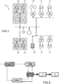
- the figure 1 represents an electrical distribution network 10.
- the electrical distribution network includes one or more electrical sources.
- one or more electrical sources is a so-called main source 20 which is configured to impose on the network the voltage V and the frequency f of a power P circulating (or distributed) on the electrical distribution network 10.
- the main source 20 can form the network.
- the main source 20 may include a synchronous generator, in particular a generator.
- the main source 20 may include an intermittent energy source.
- the intermittent energy source can comprise a renewable energy source, and for example comprise photovoltaic panels, wind turbines, tidal turbines, thermodynamic machines.
- the intermittent energy source can be provided with an inverter (“inverter” according to Anglo-Saxon terminology) endowed with a control law conferring on the intermittent energy source a behavior of synchronous generator so that the main source forms a virtual synchronous generator.
- inverter inverter
- One or more sources may also include other sources, advantageously intermittent sources 21, even more advantageously sources of renewable energy.
- renewable energy sources can include photovoltaic panels, wind turbines, tidal turbines, thermodynamic machines.
- the at least one source can comprise one or more batteries 22.
- one or more sources can comprise one or more generators 23, for example synchronous generators, asynchronous generators, or a combination of the two.
- the method according to the present invention comprises an adjustment step, within the framework of a primary regulation, which maintains essentially constant the ratio of the voltage V on the frequency f.
- the adjustment step comprises an adjustment of the voltage V so as to maintain essentially constant the ratio of the voltage V on the frequency f.
- the adjustment step comprises an adjustment of the frequency f so as to maintain essentially constant the ratio of the voltage V on the frequency f.
- Such variations in frequency and / or voltage of the power P circulating on the electrical distribution network can occur during load calls or when a fault occurs.
- This regulation is implemented by the main source which is able to form the network.
- the main source 20 may include a regulator R configured to provide regulation according to the terms of the invention.
- the regulator can measure the frequency f and the voltage V of the electrical power P.
- the measurement is carried out at regular time intervals, for example every second.
- This measure establishes the state of the network and also detects the occurrence of an event such as a load call or the appearance of a fault.
- the figure 2 is a schematic representation of the implementation of the regulation according to the present invention.
- the figure 2 represents a main source 20 connected to an electrical distribution network 10 distributing a power P to a load 30.
- the main source 20 is associated with a regulator provided with sub-modules, and in particular a frequency regulation module 20a, a voltage regulation module 20b and a control module 20c of the frequency regulation module 20a and the voltage regulation module 20b.
- the frequency regulation module 20a requires the main source 20 to adjust the frequency of a power circulating on the network to a given frequency.
- the voltage regulation module 20b requires the main source 20 to adjust the voltage of a power circulating on the network to a given voltage.
- the control module 20c indicates to the frequency module 20a and to the voltage regulation module 20b, respectively, the frequency f and the voltage V that the primary source must impose on the network.
- the measurement of the voltage V and the frequency f of the power P circulating on the network are measured by the control module 20c.
- the regulation thus proposed makes it possible to preserve a balance between power consumed and power produced at all times regardless of the state of any primary reserve.
- the regulation can also incorporate a frequency and / or voltage modulation by droop if a sufficient primary reserve is immediately available to respond to a given event.
- the regulation proposed according to the present invention is also advantageous insofar as it does not require communication between the various pieces of equipment, and in particular the sources of energy, connected to the network.
- the primary regulation can be followed by a secondary regulation allowing the frequency f and the voltage V of the network to be restored to predetermined values.
- the invention also relates to a computer program, comprising instructions which, when executed by a computer, lead to implementing the method according to the present invention.
- the invention also relates to an energy source configured to impose on a network the voltage V and the frequency f of a power P circulating on said network, and provided with the computer program according to the present invention.
- the method according to the present invention was the subject of various simulations.
- the inventors simulated the behavior of a combination of a generator forming the network (or "grid former” according to Anglo-Saxon terminology) and a synchronous generator.
- figure 3A represents the voltage delivered (vertical axis) as a function of time (horizontal axis) by the generator forming the network (curve A1) and by the synchronous generator (curve B1).
- the figure 3B represents the active power delivered (vertical axis) as a function of time (horizontal axis) by the generator forming the network (curve A2) and by the synchronous generator (curve B2).
- the figure 3C represents the reactive power delivered (vertical axis) as a function of time (horizontal axis) by the generator forming the network (curve A3) and by the synchronous generator (curve B3).
- the 3D figure represents the frequency f delivered (vertical axis) as a function of time (horizontal axis) by generator forming the network (curve A4) and by the synchronous generator (curve B4).
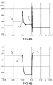
- the inventors have simulated the behavior of an inverter forming the network.
- the figure 4A represents the active power delivered by the inverter (vertical axis) as a function of time (horizontal axis).
- the figure 4B represents the power frequency delivered by the inverter (vertical axis) as a function of time (horizontal axis).
- the figure 4C represents the current delivered by the inverter (vertical axis) as a function of time (horizontal axis).
- the figure 4D represents the voltage delivered by the inverter (vertical axis) as a function of time (horizontal axis).
- a fault appears on the network.
- the latter is materialized by a load call of 660 kW ( figure 4A ).
- the adjustment is carried out so as to maintain constant the V / f ratio according to the terms of the present invention, and thus ensure the stability of the network.
- the secondary regulation phase begins from time t 2 in order to restore the network to a state imposed by the operator.
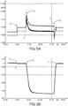
- the inventors simulated the behavior of two inverters capable of forming the network.
- the figure 5A represents the active power (vertical axis) delivered by each of the inverters as a function of time (horizontal axis).
- the figure 5B represents the power frequency (vertical axis) delivered by each of the inverters as a function of time (horizontal axis).
- the figure 5C represents the current delivered (vertical axis) delivered by each of the inverters as a function of time (horizontal axis).
- the figure 5D represents the voltage delivered (vertical axis) delivered by each of the inverters as a function of time (horizontal axis).
- the two inverters again regulate the frequency ( figure 5B ) and the voltage ( figure 5D ) so as to maintain constant the V / f ratio according to the terms of the present invention, and thus ensure the stability of the network.
- the secondary regulation phase begins from time t 2 in order to restore the network to a state imposed by the operator.
Landscapes
- Engineering & Computer Science (AREA)
- Power Engineering (AREA)
- Supply And Distribution Of Alternating Current (AREA)
- Remote Monitoring And Control Of Power-Distribution Networks (AREA)
Applications Claiming Priority (1)
| Application Number | Priority Date | Filing Date | Title |
|---|---|---|---|
| FR1873570A FR3090916B1 (fr) | 2018-12-20 | 2018-12-20 | Procede de regulation d’un reseau de distribution electrique |
Publications (2)
| Publication Number | Publication Date |
|---|---|
| EP3672011A1 true EP3672011A1 (de) | 2020-06-24 |
| EP3672011B1 EP3672011B1 (de) | 2022-10-26 |
Family
ID=67185134
Family Applications (1)
| Application Number | Title | Priority Date | Filing Date |
|---|---|---|---|
| EP19216819.3A Active EP3672011B1 (de) | 2018-12-20 | 2019-12-17 | Regulierverfahren eines stromverteilungsnetzes |
Country Status (4)
| Country | Link |
|---|---|
| US (1) | US11728652B2 (de) |
| EP (1) | EP3672011B1 (de) |
| CN (1) | CN111355248B (de) |
| FR (1) | FR3090916B1 (de) |
Citations (5)
| Publication number | Priority date | Publication date | Assignee | Title |
|---|---|---|---|---|
| EP2600479A1 (de) * | 2011-12-02 | 2013-06-05 | ABB Research Ltd. | Steuerung eines Stromnetzes mit inselartigem Betrieb |
| CN106385054A (zh) * | 2016-11-22 | 2017-02-08 | 国网辽宁省电力有限公司锦州供电公司 | 分布式光伏逆变器运行控制方法 |
| WO2018122726A1 (en) * | 2016-12-28 | 2018-07-05 | Electro Power Systems Manufacturing S.r.L. | Control system for microgrids for the production and distribution of electric power coming from multiple production sources of different types, and control method thereof |
| CN108631320A (zh) * | 2018-06-01 | 2018-10-09 | 三峡大学 | 一种基于前馈鲁棒控制的微电网电压控制方法 |
| CN108808699A (zh) * | 2018-07-10 | 2018-11-13 | 华北电力大学(保定) | 一种适用于双向储能设备的双象限频率特性分析方法 |
Family Cites Families (13)
| Publication number | Priority date | Publication date | Assignee | Title |
|---|---|---|---|---|
| US7481069B2 (en) * | 2005-07-28 | 2009-01-27 | Carrier Corporation | Controlling a voltage-to-frequency ratio for a variable speed drive in refrigerant systems |
| US20100138070A1 (en) * | 2009-02-26 | 2010-06-03 | Ronald Beaudoin | System and method for improving power grid stability |
| US9400330B2 (en) * | 2012-10-19 | 2016-07-26 | Schweitzer Engineering Laboratories, Inc. | Manipulation resilient time distribution network |
| US9042141B2 (en) * | 2013-02-07 | 2015-05-26 | Caterpillar Inc. | Control of energy storage system inverter system in a microgrid application |
| CN103345869B (zh) * | 2013-06-25 | 2016-01-06 | 武汉理工大学 | 基于复合能源并网发电的千瓦级船舶能源系统实验平台 |
| US9593672B2 (en) * | 2013-08-07 | 2017-03-14 | Siemens Aktiengesellschaft | Isochronous wind turbine generator capable of stand-alone operation |
| CN103545810B (zh) * | 2013-11-12 | 2015-07-15 | 国家电网公司 | 基于小信号稳定分析的微电网逆变器下垂自动控制方法 |
| CA2886409C (en) * | 2013-12-06 | 2016-03-22 | Rajiv Kumar Varma | Multivariable modulator controller for power generation facility |
| CN105515007A (zh) * | 2014-10-18 | 2016-04-20 | 杨利 | 电力系统电压频率调节控制器 |
| US9444257B2 (en) * | 2014-12-02 | 2016-09-13 | Osisoft, Llc | Hierarchical control of micro-grids |
| US9960637B2 (en) * | 2015-07-04 | 2018-05-01 | Sunverge Energy, Inc. | Renewable energy integrated storage and generation systems, apparatus, and methods with cloud distributed energy management services |
| CN107273586A (zh) * | 2017-05-25 | 2017-10-20 | 哈尔滨工程大学 | 一种针对太阳能船舶的光伏波动功率低成本抑制方法 |
| US10651654B2 (en) * | 2017-11-07 | 2020-05-12 | State Grid Corporation Of China | Model predictive controller for autonomous hybrid microgrids |
-
2018
- 2018-12-20 FR FR1873570A patent/FR3090916B1/fr not_active Expired - Fee Related
-
2019
- 2019-12-17 EP EP19216819.3A patent/EP3672011B1/de active Active
- 2019-12-18 US US16/719,115 patent/US11728652B2/en active Active
- 2019-12-20 CN CN201911327435.6A patent/CN111355248B/zh active Active
Patent Citations (5)
| Publication number | Priority date | Publication date | Assignee | Title |
|---|---|---|---|---|
| EP2600479A1 (de) * | 2011-12-02 | 2013-06-05 | ABB Research Ltd. | Steuerung eines Stromnetzes mit inselartigem Betrieb |
| CN106385054A (zh) * | 2016-11-22 | 2017-02-08 | 国网辽宁省电力有限公司锦州供电公司 | 分布式光伏逆变器运行控制方法 |
| WO2018122726A1 (en) * | 2016-12-28 | 2018-07-05 | Electro Power Systems Manufacturing S.r.L. | Control system for microgrids for the production and distribution of electric power coming from multiple production sources of different types, and control method thereof |
| CN108631320A (zh) * | 2018-06-01 | 2018-10-09 | 三峡大学 | 一种基于前馈鲁棒控制的微电网电压控制方法 |
| CN108808699A (zh) * | 2018-07-10 | 2018-11-13 | 华北电力大学(保定) | 一种适用于双向储能设备的双象限频率特性分析方法 |
Also Published As
| Publication number | Publication date |
|---|---|
| FR3090916B1 (fr) | 2022-06-03 |
| EP3672011B1 (de) | 2022-10-26 |
| CN111355248B (zh) | 2025-03-25 |
| US20200203955A1 (en) | 2020-06-25 |
| US11728652B2 (en) | 2023-08-15 |
| CN111355248A (zh) | 2020-06-30 |
| FR3090916A1 (fr) | 2020-06-26 |
Similar Documents
| Publication | Publication Date | Title |
|---|---|---|
| EP3185386B1 (de) | Kontrollverfahren eines elektrischen mikroverteilungsnetzes | |
| EP3208907B1 (de) | Steuerungsverfahren eines virtuellen generators | |
| Samuelsson et al. | On speed stability | |
| Yan et al. | Frequency response and its enhancement using synchronous condensers in presence of high wind penetration | |
| Vournas et al. | Postmortem analysis and data validation in the wake of the 2004 Athens blackout | |
| US10819269B2 (en) | DC integration of photovoltaic and DFIG wind turbine generation with electric storage | |
| Tuckey et al. | Decentralized control of a microgrid | |
| Dozein et al. | Frequency response capabilities of utility-scale battery energy storage systems, with application to the august 2018 separation event in australia | |
| EP3255594A1 (de) | Steuerverfahren zur erzeugung elektrischer energie network produktion und verteilung elektrischer energie | |
| Flicker et al. | Grid forming inverters for spinning reserve in hybrid diesel microgrids | |
| US12266943B2 (en) | Command generation device and command generation method in multiple power generation power supply system | |
| EP3672011B1 (de) | Regulierverfahren eines stromverteilungsnetzes | |
| US20220166224A1 (en) | Combined electric power generations' supply system in off grid independent operation | |
| Frack et al. | Control-strategy design for frequency control in autonomous smart microgrids | |
| Zhang | Adaptive energy storage system control for microgrid stability enhancement | |
| Munkhchuluun et al. | Optimal battery sizing for large-scale solar-PV generation to improve frequency stability | |
| EP4203222B1 (de) | Verfahren zur gemeinsamen spannungsregelung in einem mittelspannungszweig und niederspannungszweig mit einem dreiphasigen niederspannungszweig | |
| US11437817B2 (en) | Method and device for driving an electricity production assembly, and associated production assembly | |
| CA3183945A1 (fr) | Procede de pilotage de charge et de decharge d'une pluralite de dispositifs de stockage d'energie electrique | |
| Kumar et al. | Grid stability analysis for high penetration solar photovoltaics | |
| Zadeh et al. | Model-Driven Microgrid Controller | |
| Almeida et al. | Electric vehicles in automatic generation control for systems with large integration of renewables | |
| Aktarujjaman et al. | Dynamics of a hydro-wind hybrid isolated power system | |
| EP2533391B1 (de) | Multi-Source-Steuerungssystem von Stromgeneratoren | |
| Mendes et al. | The role of demand response in power systems with low inertia |
Legal Events
| Date | Code | Title | Description |
|---|---|---|---|
| PUAI | Public reference made under article 153(3) epc to a published international application that has entered the european phase |
Free format text: ORIGINAL CODE: 0009012 |
|
| STAA | Information on the status of an ep patent application or granted ep patent |
Free format text: STATUS: THE APPLICATION HAS BEEN PUBLISHED |
|
| AK | Designated contracting states |
Kind code of ref document: A1 Designated state(s): AL AT BE BG CH CY CZ DE DK EE ES FI FR GB GR HR HU IE IS IT LI LT LU LV MC MK MT NL NO PL PT RO RS SE SI SK SM TR |
|
| AX | Request for extension of the european patent |
Extension state: BA ME |
|
| STAA | Information on the status of an ep patent application or granted ep patent |
Free format text: STATUS: REQUEST FOR EXAMINATION WAS MADE |
|
| 17P | Request for examination filed |
Effective date: 20201120 |
|
| RBV | Designated contracting states (corrected) |
Designated state(s): AL AT BE BG CH CY CZ DE DK EE ES FI FR GB GR HR HU IE IS IT LI LT LU LV MC MK MT NL NO PL PT RO RS SE SI SK SM TR |
|
| REG | Reference to a national code |
Ref country code: DE Ref legal event code: R079 Ref document number: 602019021065 Country of ref document: DE Free format text: PREVIOUS MAIN CLASS: H02J0003240000 Ipc: H02J0003460000 |
|
| GRAJ | Information related to disapproval of communication of intention to grant by the applicant or resumption of examination proceedings by the epo deleted |
Free format text: ORIGINAL CODE: EPIDOSDIGR1 |
|
| GRAP | Despatch of communication of intention to grant a patent |
Free format text: ORIGINAL CODE: EPIDOSNIGR1 |
|
| GRAP | Despatch of communication of intention to grant a patent |
Free format text: ORIGINAL CODE: EPIDOSNIGR1 |
|
| STAA | Information on the status of an ep patent application or granted ep patent |
Free format text: STATUS: GRANT OF PATENT IS INTENDED |
|
| RIC1 | Information provided on ipc code assigned before grant |
Ipc: H02J 3/48 20060101ALI20220429BHEP Ipc: H02J 3/38 20060101ALI20220429BHEP Ipc: H02J 3/28 20060101ALI20220429BHEP Ipc: H02J 3/24 20060101ALI20220429BHEP Ipc: H02J 3/46 20060101AFI20220429BHEP |
|
| INTG | Intention to grant announced |
Effective date: 20220524 |
|
| GRAS | Grant fee paid |
Free format text: ORIGINAL CODE: EPIDOSNIGR3 |
|
| GRAA | (expected) grant |
Free format text: ORIGINAL CODE: 0009210 |
|
| STAA | Information on the status of an ep patent application or granted ep patent |
Free format text: STATUS: THE PATENT HAS BEEN GRANTED |
|
| AK | Designated contracting states |
Kind code of ref document: B1 Designated state(s): AL AT BE BG CH CY CZ DE DK EE ES FI FR GB GR HR HU IE IS IT LI LT LU LV MC MK MT NL NO PL PT RO RS SE SI SK SM TR |
|
| REG | Reference to a national code |
Ref country code: GB Ref legal event code: FG4D Free format text: NOT ENGLISH |
|
| REG | Reference to a national code |
Ref country code: CH Ref legal event code: EP |
|
| REG | Reference to a national code |
Ref country code: AT Ref legal event code: REF Ref document number: 1527769 Country of ref document: AT Kind code of ref document: T Effective date: 20221115 |
|
| REG | Reference to a national code |
Ref country code: DE Ref legal event code: R096 Ref document number: 602019021065 Country of ref document: DE |
|
| REG | Reference to a national code |
Ref country code: IE Ref legal event code: FG4D Free format text: LANGUAGE OF EP DOCUMENT: FRENCH |
|
| REG | Reference to a national code |
Ref country code: LT Ref legal event code: MG9D |
|
| REG | Reference to a national code |
Ref country code: NL Ref legal event code: MP Effective date: 20221026 |
|
| REG | Reference to a national code |
Ref country code: AT Ref legal event code: MK05 Ref document number: 1527769 Country of ref document: AT Kind code of ref document: T Effective date: 20221026 |
|
| PG25 | Lapsed in a contracting state [announced via postgrant information from national office to epo] |
Ref country code: NL Free format text: LAPSE BECAUSE OF FAILURE TO SUBMIT A TRANSLATION OF THE DESCRIPTION OR TO PAY THE FEE WITHIN THE PRESCRIBED TIME-LIMIT Effective date: 20221026 |
|
| PG25 | Lapsed in a contracting state [announced via postgrant information from national office to epo] |
Ref country code: SE Free format text: LAPSE BECAUSE OF FAILURE TO SUBMIT A TRANSLATION OF THE DESCRIPTION OR TO PAY THE FEE WITHIN THE PRESCRIBED TIME-LIMIT Effective date: 20221026 Ref country code: PT Free format text: LAPSE BECAUSE OF FAILURE TO SUBMIT A TRANSLATION OF THE DESCRIPTION OR TO PAY THE FEE WITHIN THE PRESCRIBED TIME-LIMIT Effective date: 20230227 Ref country code: NO Free format text: LAPSE BECAUSE OF FAILURE TO SUBMIT A TRANSLATION OF THE DESCRIPTION OR TO PAY THE FEE WITHIN THE PRESCRIBED TIME-LIMIT Effective date: 20230126 Ref country code: LT Free format text: LAPSE BECAUSE OF FAILURE TO SUBMIT A TRANSLATION OF THE DESCRIPTION OR TO PAY THE FEE WITHIN THE PRESCRIBED TIME-LIMIT Effective date: 20221026 Ref country code: FI Free format text: LAPSE BECAUSE OF FAILURE TO SUBMIT A TRANSLATION OF THE DESCRIPTION OR TO PAY THE FEE WITHIN THE PRESCRIBED TIME-LIMIT Effective date: 20221026 Ref country code: ES Free format text: LAPSE BECAUSE OF FAILURE TO SUBMIT A TRANSLATION OF THE DESCRIPTION OR TO PAY THE FEE WITHIN THE PRESCRIBED TIME-LIMIT Effective date: 20221026 Ref country code: AT Free format text: LAPSE BECAUSE OF FAILURE TO SUBMIT A TRANSLATION OF THE DESCRIPTION OR TO PAY THE FEE WITHIN THE PRESCRIBED TIME-LIMIT Effective date: 20221026 |
|
| PG25 | Lapsed in a contracting state [announced via postgrant information from national office to epo] |
Ref country code: RS Free format text: LAPSE BECAUSE OF FAILURE TO SUBMIT A TRANSLATION OF THE DESCRIPTION OR TO PAY THE FEE WITHIN THE PRESCRIBED TIME-LIMIT Effective date: 20221026 Ref country code: PL Free format text: LAPSE BECAUSE OF FAILURE TO SUBMIT A TRANSLATION OF THE DESCRIPTION OR TO PAY THE FEE WITHIN THE PRESCRIBED TIME-LIMIT Effective date: 20221026 Ref country code: LV Free format text: LAPSE BECAUSE OF FAILURE TO SUBMIT A TRANSLATION OF THE DESCRIPTION OR TO PAY THE FEE WITHIN THE PRESCRIBED TIME-LIMIT Effective date: 20221026 Ref country code: IS Free format text: LAPSE BECAUSE OF FAILURE TO SUBMIT A TRANSLATION OF THE DESCRIPTION OR TO PAY THE FEE WITHIN THE PRESCRIBED TIME-LIMIT Effective date: 20230226 Ref country code: HR Free format text: LAPSE BECAUSE OF FAILURE TO SUBMIT A TRANSLATION OF THE DESCRIPTION OR TO PAY THE FEE WITHIN THE PRESCRIBED TIME-LIMIT Effective date: 20221026 Ref country code: GR Free format text: LAPSE BECAUSE OF FAILURE TO SUBMIT A TRANSLATION OF THE DESCRIPTION OR TO PAY THE FEE WITHIN THE PRESCRIBED TIME-LIMIT Effective date: 20230127 |
|
| REG | Reference to a national code |
Ref country code: DE Ref legal event code: R097 Ref document number: 602019021065 Country of ref document: DE |
|
| PG25 | Lapsed in a contracting state [announced via postgrant information from national office to epo] |
Ref country code: SM Free format text: LAPSE BECAUSE OF FAILURE TO SUBMIT A TRANSLATION OF THE DESCRIPTION OR TO PAY THE FEE WITHIN THE PRESCRIBED TIME-LIMIT Effective date: 20221026 Ref country code: RO Free format text: LAPSE BECAUSE OF FAILURE TO SUBMIT A TRANSLATION OF THE DESCRIPTION OR TO PAY THE FEE WITHIN THE PRESCRIBED TIME-LIMIT Effective date: 20221026 Ref country code: EE Free format text: LAPSE BECAUSE OF FAILURE TO SUBMIT A TRANSLATION OF THE DESCRIPTION OR TO PAY THE FEE WITHIN THE PRESCRIBED TIME-LIMIT Effective date: 20221026 Ref country code: DK Free format text: LAPSE BECAUSE OF FAILURE TO SUBMIT A TRANSLATION OF THE DESCRIPTION OR TO PAY THE FEE WITHIN THE PRESCRIBED TIME-LIMIT Effective date: 20221026 Ref country code: CZ Free format text: LAPSE BECAUSE OF FAILURE TO SUBMIT A TRANSLATION OF THE DESCRIPTION OR TO PAY THE FEE WITHIN THE PRESCRIBED TIME-LIMIT Effective date: 20221026 |
|
| REG | Reference to a national code |
Ref country code: CH Ref legal event code: PL |
|
| REG | Reference to a national code |
Ref country code: BE Ref legal event code: MM Effective date: 20221231 |
|
| PG25 | Lapsed in a contracting state [announced via postgrant information from national office to epo] |
Ref country code: SK Free format text: LAPSE BECAUSE OF FAILURE TO SUBMIT A TRANSLATION OF THE DESCRIPTION OR TO PAY THE FEE WITHIN THE PRESCRIBED TIME-LIMIT Effective date: 20221026 Ref country code: LU Free format text: LAPSE BECAUSE OF NON-PAYMENT OF DUE FEES Effective date: 20221217 Ref country code: AL Free format text: LAPSE BECAUSE OF FAILURE TO SUBMIT A TRANSLATION OF THE DESCRIPTION OR TO PAY THE FEE WITHIN THE PRESCRIBED TIME-LIMIT Effective date: 20221026 |
|
| PLBE | No opposition filed within time limit |
Free format text: ORIGINAL CODE: 0009261 |
|
| STAA | Information on the status of an ep patent application or granted ep patent |
Free format text: STATUS: NO OPPOSITION FILED WITHIN TIME LIMIT |
|
| 26N | No opposition filed |
Effective date: 20230727 |
|
| PG25 | Lapsed in a contracting state [announced via postgrant information from national office to epo] |
Ref country code: LI Free format text: LAPSE BECAUSE OF NON-PAYMENT OF DUE FEES Effective date: 20221231 Ref country code: IE Free format text: LAPSE BECAUSE OF NON-PAYMENT OF DUE FEES Effective date: 20221217 Ref country code: CH Free format text: LAPSE BECAUSE OF NON-PAYMENT OF DUE FEES Effective date: 20221231 |
|
| PG25 | Lapsed in a contracting state [announced via postgrant information from national office to epo] |
Ref country code: SI Free format text: LAPSE BECAUSE OF FAILURE TO SUBMIT A TRANSLATION OF THE DESCRIPTION OR TO PAY THE FEE WITHIN THE PRESCRIBED TIME-LIMIT Effective date: 20221026 Ref country code: BE Free format text: LAPSE BECAUSE OF NON-PAYMENT OF DUE FEES Effective date: 20221231 |
|
| PG25 | Lapsed in a contracting state [announced via postgrant information from national office to epo] |
Ref country code: HU Free format text: LAPSE BECAUSE OF FAILURE TO SUBMIT A TRANSLATION OF THE DESCRIPTION OR TO PAY THE FEE WITHIN THE PRESCRIBED TIME-LIMIT; INVALID AB INITIO Effective date: 20191217 |
|
| PG25 | Lapsed in a contracting state [announced via postgrant information from national office to epo] |
Ref country code: CY Free format text: LAPSE BECAUSE OF FAILURE TO SUBMIT A TRANSLATION OF THE DESCRIPTION OR TO PAY THE FEE WITHIN THE PRESCRIBED TIME-LIMIT Effective date: 20221026 |
|
| PG25 | Lapsed in a contracting state [announced via postgrant information from national office to epo] |
Ref country code: MK Free format text: LAPSE BECAUSE OF FAILURE TO SUBMIT A TRANSLATION OF THE DESCRIPTION OR TO PAY THE FEE WITHIN THE PRESCRIBED TIME-LIMIT Effective date: 20221026 Ref country code: IT Free format text: LAPSE BECAUSE OF FAILURE TO SUBMIT A TRANSLATION OF THE DESCRIPTION OR TO PAY THE FEE WITHIN THE PRESCRIBED TIME-LIMIT Effective date: 20221026 |
|
| PG25 | Lapsed in a contracting state [announced via postgrant information from national office to epo] |
Ref country code: MC Free format text: LAPSE BECAUSE OF FAILURE TO SUBMIT A TRANSLATION OF THE DESCRIPTION OR TO PAY THE FEE WITHIN THE PRESCRIBED TIME-LIMIT Effective date: 20221026 |
|
| PG25 | Lapsed in a contracting state [announced via postgrant information from national office to epo] |
Ref country code: MC Free format text: LAPSE BECAUSE OF FAILURE TO SUBMIT A TRANSLATION OF THE DESCRIPTION OR TO PAY THE FEE WITHIN THE PRESCRIBED TIME-LIMIT Effective date: 20221026 |
|
| PG25 | Lapsed in a contracting state [announced via postgrant information from national office to epo] |
Ref country code: BG Free format text: LAPSE BECAUSE OF FAILURE TO SUBMIT A TRANSLATION OF THE DESCRIPTION OR TO PAY THE FEE WITHIN THE PRESCRIBED TIME-LIMIT Effective date: 20221026 |
|
| PG25 | Lapsed in a contracting state [announced via postgrant information from national office to epo] |
Ref country code: MT Free format text: LAPSE BECAUSE OF FAILURE TO SUBMIT A TRANSLATION OF THE DESCRIPTION OR TO PAY THE FEE WITHIN THE PRESCRIBED TIME-LIMIT Effective date: 20221026 |
|
| PG25 | Lapsed in a contracting state [announced via postgrant information from national office to epo] |
Ref country code: TR Free format text: LAPSE BECAUSE OF FAILURE TO SUBMIT A TRANSLATION OF THE DESCRIPTION OR TO PAY THE FEE WITHIN THE PRESCRIBED TIME-LIMIT Effective date: 20221026 |
|
| PGFP | Annual fee paid to national office [announced via postgrant information from national office to epo] |
Ref country code: GB Payment date: 20251223 Year of fee payment: 7 |
|
| PGFP | Annual fee paid to national office [announced via postgrant information from national office to epo] |
Ref country code: FR Payment date: 20251230 Year of fee payment: 7 |
|
| PGFP | Annual fee paid to national office [announced via postgrant information from national office to epo] |
Ref country code: DE Payment date: 20251229 Year of fee payment: 7 |