EP3731398A1 - Steuerverfahren eines gleichstrom-wechselstrom-wandlers - Google Patents
Steuerverfahren eines gleichstrom-wechselstrom-wandlers Download PDFInfo
- Publication number
- EP3731398A1 EP3731398A1 EP20170412.9A EP20170412A EP3731398A1 EP 3731398 A1 EP3731398 A1 EP 3731398A1 EP 20170412 A EP20170412 A EP 20170412A EP 3731398 A1 EP3731398 A1 EP 3731398A1
- Authority
- EP
- European Patent Office
- Prior art keywords
- converter
- synchronous generator
- mode
- current source
- routine
- Prior art date
- Legal status (The legal status is an assumption and is not a legal conclusion. Google has not performed a legal analysis and makes no representation as to the accuracy of the status listed.)
- Ceased
Links
Images


Classifications
-
- H—ELECTRICITY
- H02—GENERATION; CONVERSION OR DISTRIBUTION OF ELECTRIC POWER
- H02J—ELECTRIC POWER NETWORKS; CIRCUIT ARRANGEMENTS OR SYSTEMS FOR SUPPLYING OR DISTRIBUTING ELECTRIC POWER; SYSTEMS FOR STORING ELECTRIC ENERGY
- H02J3/00—Circuit arrangements for AC mains or AC distribution networks
- H02J3/38—Arrangements for feeding a single network from two or more generators or sources in parallel; Arrangements for feeding already energised networks from additional generators or sources in parallel
- H02J3/381—Dispersed generators
-
- H—ELECTRICITY
- H02—GENERATION; CONVERSION OR DISTRIBUTION OF ELECTRIC POWER
- H02J—ELECTRIC POWER NETWORKS; CIRCUIT ARRANGEMENTS OR SYSTEMS FOR SUPPLYING OR DISTRIBUTING ELECTRIC POWER; SYSTEMS FOR STORING ELECTRIC ENERGY
- H02J3/00—Circuit arrangements for AC mains or AC distribution networks
- H02J3/38—Arrangements for feeding a single network from two or more generators or sources in parallel; Arrangements for feeding already energised networks from additional generators or sources in parallel
- H02J3/388—Arrangements for the handling of islanding, e.g. for disconnection or for avoiding the disconnection of power
-
- H—ELECTRICITY
- H02—GENERATION; CONVERSION OR DISTRIBUTION OF ELECTRIC POWER
- H02J—ELECTRIC POWER NETWORKS; CIRCUIT ARRANGEMENTS OR SYSTEMS FOR SUPPLYING OR DISTRIBUTING ELECTRIC POWER; SYSTEMS FOR STORING ELECTRIC ENERGY
- H02J3/00—Circuit arrangements for AC mains or AC distribution networks
- H02J3/001—Arrangements for handling faults or abnormalities, e.g. emergencies or contingencies
- H02J3/0014—Arrangements for handling faults or abnormalities, e.g. emergencies or contingencies for preventing or reducing power oscillations in networks
-
- H—ELECTRICITY
- H02—GENERATION; CONVERSION OR DISTRIBUTION OF ELECTRIC POWER
- H02M—APPARATUS FOR CONVERSION BETWEEN AC AND AC, BETWEEN AC AND DC, OR BETWEEN DC AND DC, AND FOR USE WITH MAINS OR SIMILAR POWER SUPPLY SYSTEMS; CONVERSION OF DC OR AC INPUT POWER INTO SURGE OUTPUT POWER; CONTROL OR REGULATION THEREOF
- H02M1/00—Details of apparatus for conversion
- H02M1/42—Circuits or arrangements for compensating for or adjusting power factor in converters or inverters
-
- H—ELECTRICITY
- H02—GENERATION; CONVERSION OR DISTRIBUTION OF ELECTRIC POWER
- H02M—APPARATUS FOR CONVERSION BETWEEN AC AND AC, BETWEEN AC AND DC, OR BETWEEN DC AND DC, AND FOR USE WITH MAINS OR SIMILAR POWER SUPPLY SYSTEMS; CONVERSION OF DC OR AC INPUT POWER INTO SURGE OUTPUT POWER; CONTROL OR REGULATION THEREOF
- H02M7/00—Conversion of AC power input into DC power output; Conversion of DC power input into AC power output
- H02M7/42—Conversion of DC power input into AC power output without possibility of reversal
- H02M7/44—Conversion of DC power input into AC power output without possibility of reversal by static converters
- H02M7/48—Conversion of DC power input into AC power output without possibility of reversal by static converters using discharge tubes with control electrode or semiconductor devices with control electrode
-
- H—ELECTRICITY
- H02—GENERATION; CONVERSION OR DISTRIBUTION OF ELECTRIC POWER
- H02J—ELECTRIC POWER NETWORKS; CIRCUIT ARRANGEMENTS OR SYSTEMS FOR SUPPLYING OR DISTRIBUTING ELECTRIC POWER; SYSTEMS FOR STORING ELECTRIC ENERGY
- H02J2103/00—Details of circuit arrangements for mains or AC distribution networks
- H02J2103/30—Simulating, planning, modelling, reliability check or computer assisted design [CAD] of electric power networks
-
- H—ELECTRICITY
- H02—GENERATION; CONVERSION OR DISTRIBUTION OF ELECTRIC POWER
- H02M—APPARATUS FOR CONVERSION BETWEEN AC AND AC, BETWEEN AC AND DC, OR BETWEEN DC AND DC, AND FOR USE WITH MAINS OR SIMILAR POWER SUPPLY SYSTEMS; CONVERSION OF DC OR AC INPUT POWER INTO SURGE OUTPUT POWER; CONTROL OR REGULATION THEREOF
- H02M1/00—Details of apparatus for conversion
- H02M1/0003—Details of control, feedback or regulation circuits
-
- H—ELECTRICITY
- H02—GENERATION; CONVERSION OR DISTRIBUTION OF ELECTRIC POWER
- H02M—APPARATUS FOR CONVERSION BETWEEN AC AND AC, BETWEEN AC AND DC, OR BETWEEN DC AND DC, AND FOR USE WITH MAINS OR SIMILAR POWER SUPPLY SYSTEMS; CONVERSION OF DC OR AC INPUT POWER INTO SURGE OUTPUT POWER; CONTROL OR REGULATION THEREOF
- H02M7/00—Conversion of AC power input into DC power output; Conversion of DC power input into AC power output
- H02M7/42—Conversion of DC power input into AC power output without possibility of reversal
- H02M7/44—Conversion of DC power input into AC power output without possibility of reversal by static converters
- H02M7/48—Conversion of DC power input into AC power output without possibility of reversal by static converters using discharge tubes with control electrode or semiconductor devices with control electrode
- H02M7/483—Converters with outputs that each can have more than two voltages levels
Definitions
- the present invention relates to a method for controlling a DC / AC converter.
- the present invention relates to a method for controlling a converter making it possible to switch the latter from a current source mode to a mode conforming to that of a virtual synchronous generator.
- DC / AC converters are widely used today in power distribution networks. Their implementation is notably imposed by the emergence of unconventional energy sources such as renewable energy sources, but also by the implementation of primary reserves such as batteries or even flywheels (" Fly Wheel ”according to Anglo-Saxon terminology).
- a converter when connected to an electrical distribution network, it is synchronized with the electrical distribution network via a phase-locked loop (“PLL” or “Phase Lock Loop” according to Anglo-Saxon terminology), and supplies it with an active power P and a reactive power Q regulated via a power control loop (“Power Control Loop” according to Anglo-Saxon terminology) and on the basis of the voltage V and of the frequency F of the electrical distribution network.
- PLL phase-locked loop
- Power Control Loop Power Control Loop
- a converter operating as a current source is simple to implement, and provides relative stability to the electrical distribution network.
- the virtual synchronous generators (such as that described in the document [1] cited at the end of the description) occupy a place of choice.
- the latter can easily be connected in parallel with other energy sources such as generators, in order to distribute the loads connected to the electrical distribution network.
- the virtual synchronous generator mode represents a certain danger for operators, and requires special precautions to be taken during maintenance operations.
- This switching from current source mode to synchronous generator mode may in particular occur following a voluntary disconnection (by a programmed islanding) or involuntary disconnection of a so-called “strong” distribution network (“Infinity bus” according to Anglo terminology). -Saxonne).
- An aim of the present invention is therefore to provide a method for controlling a converter making it possible to eliminate the voltage and frequency instabilities liable to occur when switching said converter from a current source mode to a synchronous generator mode. virtual.
- Another aim of the present invention is to provide a method for controlling a converter making it possible to guarantee the safety of persons operating on said converter.
- the objects of the invention are, at least in part, achieved by a method for controlling a DC / AC converter connected to an electrical network, the converter being controlled by a control law configured to require the converter to operate. , by default, in current source mode, and in the event of disappearance of the electrical network, controls the switching of said converter from current source mode to a virtual synchronous generator mode, the control law also being configured for, as long as the converter operates in current source mode, monitoring the frequency and phase of the electrical network making it possible to initialize the emulation of the virtual synchronous generator mode, by said control law, at the time of detection of the disappearance of the electrical network.
- control law comprises two routines called, respectively, current source routine and synchronous generator routine implementing, respectively, the control in current source mode and the control in virtual synchronous generator mode of the converter.
- the current source routine comprises phase locked loop which, from the frequency and the angle of the calculation network, makes it possible to synchronize, in terms of phase and phase angle, the current delivered by the converter to the electrical network.
- the current source routine also includes a power control loop intended to estimate a reference current that the converter must deliver as a function of an active power P and a reactive power Q necessary for the operation of the device. electrical network.
- the synchronous generator routine continuously calculates a reference current, a reference voltage compatible with the operation of a synchronous generator configured to form the network.
- the reference current is a current that a synchronous generator would supply if it were subjected to the voltage measured at the output terminals of said converter.
- the frequency and phase of the network monitored by the control law are implemented to synchronize the reference voltage and the reference current calculated by the synchronous generator routine.
- control law further comprises a changeover management module which, by default, imposes control of the converter by the current source routine, and as soon as the network disappears, imposes a control of the converter by the synchronous generator routine.
- the invention also relates to a computer program comprising instructions which, when the program is executed by a computer, lead to the implementation of the control method according to the present invention.
- the invention also relates to a direct current to alternating current converter provided with the computer program according to the present invention.
- the invention relates to a method for controlling a DC / AC converter (hereinafter “converter”). More particularly, the invention relates to a method for controlling a converter making it possible to switch the latter from a current source mode to a mode conforming to that of a virtual synchronous generator.
- converter DC / AC converter
- the converter may be a direct current to alternating current converter or a direct voltage to alternating voltage converter.
- the remainder of the description will however be limited to the use of a voltage converter.
- the control method is executed by a control law which, by default, requires the converter to operate in current source mode, and in the event of the disappearance of the electrical network, in particular a strong electrical network, controls the switching from the current source mode to virtual synchronous generator mode.
- the control law is also configured to continuously monitor the frequency and phase of the network, and to emulate, from these data, the virtual synchronous generator mode. This emulation, executed in the background when the converter is operating in current source mode, makes it possible to switch without power interruption for the electrical load (s) from current source mode to virtual synchronous generator mode when a failure of the network or that islanding of the latter occurs.
- the figure 2 is a schematic representation of the various blocks of a control law 200 capable of being implemented for controlling a converter 100 according to the present invention.
- the converter 100 is connected to an electrical distribution network 110 subjected to a voltage V of frequency "f” and phase angle “ ⁇ ” (hereinafter “the phase ⁇ ”), imposed by one or more voltage source (s) capable of forming the network.
- V of frequency "f” and phase angle “ ⁇ ” hereinafter “the phase ⁇ ”
- the converter 100 converts the direct voltage generated by a power source 120 into an alternating voltage.
- the power source 120 may include a DC voltage source.
- a direct voltage source can include, for example, photovoltaic panels, wind turbines, tidal turbines, thermodynamic machines, batteries or even flywheels.
- the converter 100 can comprise, in the case of a three-level inverter, two capacitors C + and C - connected together in series to form an equivalent capacitor C.
- the terminals of the equivalent capacitor C are electrically connected, for example in parallel at the terminals of the energy source 120.
- the use of the two capacitors C + and C - makes it possible to guarantee an undeformed sinusoidal shape of the current supplied by the converter 100 to the electrical distribution network.
- the invention is however not limited to the use of a three-level inverter.
- the operation of the converter 100 is governed by a control law 200.
- the control law 200 in particular requires the converter to operate by default in current source mode (“Grid Tie” according to Anglo-Saxon terminology).
- the converter 100 is subjected to the frequency f and the phase angle ⁇ imposed by the network 110.
- frequency f and phase angle ⁇ of the network is meant the frequency and phase of the voltage of the electrical distribution network 110.
- the control law 200 can, in this regard, include a routine dedicated to this operating mode, called a current source routine 300.
- the current source routine 300 can in particular comprise a Park module 310, a PLL module 320 (PLL for phase locked loop), a network phase calculation module 330 and a PCL 340 module (PCL for power control loop).
- PLL phase locked loop
- PCL PCL for power control loop
- the Park module 310 is in particular dedicated to monitoring the voltage V abc of the network, and from which the frequency f and the phase ⁇ are extracted, respectively, by the PLL module 320 and the calculation module 330.
- the function of the Park module 310 is to transform the voltages, for example the three alternating voltages V abc of the network 110, into two direct voltages V dq which are used by the modules 320 and 330 to respectively estimate the frequency and the phase network 110.
- the PCL module calculates a reference current I ref, GT associated with an active power P ref and a reactive power Q ref that the converter 100 must deliver to the electrical distribution network 110.
- the control law 200 also includes a current regulation routine 400 provided with a current regulation module 410 and a pulse generation module 420 ("PWM” or “Pulsation Width Modulation) according to English terminology. Saxon)
- the pulse generation module 420 requires the converter 100 to apply duty cycles, calculated by the current regulation module 410, and allowing said converter to deliver to the electrical distribution network the current I ref, GT at the frequency f and at phase ⁇ of network 110.
- the control law 200 is also suitable for imposing a switch from the current source mode to a virtual synchronous generator mode in the event of the network disappearing.
- the “disappearance of the network” can for example occur following a failure of this denier or of an islanding, for example a programmed islanding.
- the synchronous generator mode is a mode in which the converter behaves like a generator set.
- control law 200 may include a routine dedicated to this mode of operation, called a synchronous generator routine 500.
- a generator set generally comprises a rotor driven in rotation in a stator and an automatic voltage regulator (“AVR” or “Automatic Voltage Regulator” according to Anglo-Saxon terminology) acting on the rotor windings of the rotor.
- the automatic voltage regulator thus applies a voltage to the rotor windings as a function of the effective voltage V rms (of the voltage V) delivered by the stator (by the generator set) to the network.
- the voltage / reactive power droop control Q allows the generator set to adapt the effective voltage V rms that it delivers as a function of the reactive electric power Q that it supplies.
- the rotor of a generator set is generally driven in rotation, by a shaft of a heat engine (for example a diesel engine), inside a stator.
- a heat engine for example a diesel engine
- the generator set is capable of forming the network.
- the generator set can impose the voltage V and the frequency f on an electrical network.
- the synchronous generator routine 500 comprises modules 540 and 550, described in more detail in the remainder of the description, which, respectively, continuously generate the frequency f and the phase ⁇ of the network. More particularly, the modules 540 and 550 are permanently initialized at the frequency and voltage of the network in cooperation with a changeover management module 600. This initialization of the modules 540 and 550 also makes it possible to calculate a reference current I ref, GF , that a generator capable of forming the network would deliver.
- these parameters are not communicated to the current regulation routine 400 as long as the converter 100 is operating in current source mode.
- the modules 540 and 550 of the synchronous generator routine 500 run in the background as long as no network failure is detected or no islanding command is issued.
- these modules 540 and 550 are constantly initialized to the frequency and to the angle of the network.
- the synchronous generator routine 500 takes over from the current source routine 300 almost instantaneously and imposes on the converter 100 a synchronous generator behavior so that the latter is able to form the network.
- the synchronous generator routine 500 continuously calculates the current I ref, GF .
- This switching from the current source mode to the synchronous generator mode can be controlled by a changeover management module 600 which by default imposes control of the converter by the current source routine and, in the event of a network failure, imposes control of the converter by the synchronous generator routine.
- the changeover management module 600 thus makes it possible to permanently and correctly initialize the internal states of the control by the synchronous generator routine 500 so that the latter is “ready” when switching from the current source mode to the generator mode. virtual synchronous. Thus according to the present invention, it is possible to limit the transient effects on the current and the voltage during switching.
- the synchronous generator routine 500 can, in accordance with the virtual synchronous generator described in the document [1] cited at the end of the description, comprise an AVR 510 module (AVR for automatic voltage regulator), a governor 520 module, a synchronous machine module 530, the mechanical equations module 540 and the internal angle calculation module of the synchronous machine 550, a current limiting module 560.
- AVR 510 module AVR for automatic voltage regulator
- governor 520 module for automatic voltage regulator
- a synchronous machine module 530 the mechanical equations module 540 and the internal angle calculation module of the synchronous machine 550
- a current limiting module 560 a current limiting module 560.
- the AVR 510 module is intended in particular to regulate the voltage at the output terminals of the converter 100.
- the governor module 520 is intended to regulate the frequency of the current capable of being delivered by the converter.
- the synchronous machine module 530 comprises all of the differential equations relating to the electrical operation of a synchronous machine which is a component of a generator set.
- the mechanical equation module 540 includes the mechanical equations of a rotating shaft.
- the method according to the present invention therefore makes it possible to limit the transient effects due to the switching from the current source mode to the virtual synchronous generator mode.
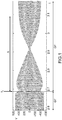
- the figures 3a and 3b represent a simulation of the method according to the present invention.
- the figures 3a and 3b represent the evolution, respectively, of the voltage V abc (vertical axis) and of the current intensity (vertical axis) as a function of time following a loss of network at an instant t 1 .
- This tilting takes place, unlike the tilting observed at the figure 1 , without major instability.
- the invention also relates to a computer program comprising instructions which, when the program is executed by a computer, lead to the implementation of the control method according to the present invention.
- the invention also relates to a DC / AC converter provided with the computer program according to the present invention.
Landscapes
- Engineering & Computer Science (AREA)
- Power Engineering (AREA)
- Control Of Eletrric Generators (AREA)
- Rectifiers (AREA)
Applications Claiming Priority (1)
| Application Number | Priority Date | Filing Date | Title |
|---|---|---|---|
| FR1904362A FR3095559A1 (fr) | 2019-04-25 | 2019-04-25 | Procédé de commande d’un convertisseur dc/ac |
Publications (1)
| Publication Number | Publication Date |
|---|---|
| EP3731398A1 true EP3731398A1 (de) | 2020-10-28 |
Family
ID=67956974
Family Applications (1)
| Application Number | Title | Priority Date | Filing Date |
|---|---|---|---|
| EP20170412.9A Ceased EP3731398A1 (de) | 2019-04-25 | 2020-04-20 | Steuerverfahren eines gleichstrom-wechselstrom-wandlers |
Country Status (4)
| Country | Link |
|---|---|
| US (1) | US11394314B2 (de) |
| EP (1) | EP3731398A1 (de) |
| CN (1) | CN111864792A (de) |
| FR (1) | FR3095559A1 (de) |
Cited By (1)
| Publication number | Priority date | Publication date | Assignee | Title |
|---|---|---|---|---|
| CN114024309A (zh) * | 2021-11-11 | 2022-02-08 | 广东志成冠军集团有限公司 | 孤岛微电网系统及其交互振荡抑制方法、系统 |
Families Citing this family (2)
| Publication number | Priority date | Publication date | Assignee | Title |
|---|---|---|---|---|
| JP7536120B2 (ja) * | 2021-01-15 | 2024-08-19 | 三菱電機株式会社 | 電力変換装置 |
| US12237681B2 (en) * | 2021-02-19 | 2025-02-25 | Kabushiki Kaisha Toshiba | Microgrid startup method and startup program |
Citations (3)
| Publication number | Priority date | Publication date | Assignee | Title |
|---|---|---|---|---|
| EP3208907A1 (de) | 2016-02-16 | 2017-08-23 | Schneider Electric Industries SAS | Steuerungsverfahren eines virtuellen generators |
| CN104410097B (zh) * | 2014-09-26 | 2018-07-06 | 广东易事特电源股份有限公司 | 微网逆变器及其并网和离网的控制方法 |
| CN109494800A (zh) * | 2018-12-19 | 2019-03-19 | 上海电气分布式能源科技有限公司 | 用于微电网的并网与离网相互切换的控制方法及系统 |
Family Cites Families (2)
| Publication number | Priority date | Publication date | Assignee | Title |
|---|---|---|---|---|
| US8606424B2 (en) * | 2011-04-05 | 2013-12-10 | King Fahd University Of Petroleum And Minerals | Particle swarm optimization system and method for microgrids |
| US8957546B2 (en) * | 2012-07-10 | 2015-02-17 | Nixon Power Services, Llc | Electrical cogeneration system and method |
-
2019
- 2019-04-25 FR FR1904362A patent/FR3095559A1/fr active Pending
-
2020
- 2020-04-02 US US16/838,794 patent/US11394314B2/en active Active
- 2020-04-17 CN CN202010303944.1A patent/CN111864792A/zh active Pending
- 2020-04-20 EP EP20170412.9A patent/EP3731398A1/de not_active Ceased
Patent Citations (3)
| Publication number | Priority date | Publication date | Assignee | Title |
|---|---|---|---|---|
| CN104410097B (zh) * | 2014-09-26 | 2018-07-06 | 广东易事特电源股份有限公司 | 微网逆变器及其并网和离网的控制方法 |
| EP3208907A1 (de) | 2016-02-16 | 2017-08-23 | Schneider Electric Industries SAS | Steuerungsverfahren eines virtuellen generators |
| CN109494800A (zh) * | 2018-12-19 | 2019-03-19 | 上海电气分布式能源科技有限公司 | 用于微电网的并网与离网相互切换的控制方法及系统 |
Non-Patent Citations (7)
| Title |
|---|
| "Microgrid Technology and Engineering Application", 14 September 2015, ELSEVIER SCIENCE & TECHNOLOGY, U.S.A., ISBN: 978-0-12-803630-3, article LI FUSHENG ET AL: "P/Q control", pages: 19 - 20, XP055655905 * |
| BEVRANI HASSAN ET AL: "Virtual synchronous generators: A survey and new perspectives", INTERNATIONAL JOURNAL OF ELECTRICAL POWER & ENERGY SYSTEMS, JORDAN HILL, OXFORD, GB, vol. 54, 7 August 2013 (2013-08-07), pages 244 - 254, XP028727167, ISSN: 0142-0615, DOI: 10.1016/J.IJEPES.2013.07.009 * |
| FU YANG ET AL: "Micro-Grid Smooth Switchover Method Based on Controller State Following", 14TH INTERNATIONAL HEAT PIPE CONFERENCE (14TH IHPC), vol. 03, no. 04, 1 January 2015 (2015-01-01), pages 128 - 135, XP093106287, ISSN: 2327-588X, DOI: 10.4236/jpee.2015.34019 * |
| KHOSHKBAR SADIGH A ET AL: "Review of voltage compensation methods in dynamic voltage restorer (DVR)", 2012 IEEE POWER AND ENERGY SOCIETY GENERAL MEETING ; SAN DIEGO, CALIFORNIA, USA; 22 - 26 JULY 2012, IEEE, PISCATAWAY, NJ, 22 July 2012 (2012-07-22), pages 1 - 8, XP032465786, ISBN: 978-1-4673-2727-5, DOI: 10.1109/PESGM.2012.6345153 * |
| MALACZEK MICHAL ET AL: "Forming a microgrid to islanded operation as a mean to improve quality of supply in low voltage networks with distributed generation", 2018 18TH INTERNATIONAL CONFERENCE ON HARMONICS AND QUALITY OF POWER (ICHQP), IEEE, 13 May 2018 (2018-05-13), pages 1 - 6, XP033354925, DOI: 10.1109/ICHQP.2018.8378929 * |
| NIELSEN J G ET AL: "Control strategies for dynamic voltage restorer compensating voltage sags with phase jump", APEC 2001. 16TH. ANNUAL IEEE APPLIED POWER ELECTRONICS CONFERENCE AND EXPOSITION. ANAHEIM, CA, MARCH 4 - 8, 2001; [ANNUAL APPLIED POWER ELECTRONICS CONFERENCE], NEW YORK, NY : IEEE, US, vol. 2, 4 March 2001 (2001-03-04), pages 1267 - 1273, XP010536153, ISBN: 978-0-7803-6618-3, DOI: 10.1109/APEC.2001.912528 * |
| TIAN XUEFENG: "A photovoltaic generation system with standby power", 2014 IEEE WORKSHOP ON ELECTRONICS, COMPUTER AND APPLICATIONS, IEEE, 8 May 2014 (2014-05-08), pages 303 - 306, XP032612465, DOI: 10.1109/IWECA.2014.6845616 * |
Cited By (2)
| Publication number | Priority date | Publication date | Assignee | Title |
|---|---|---|---|---|
| CN114024309A (zh) * | 2021-11-11 | 2022-02-08 | 广东志成冠军集团有限公司 | 孤岛微电网系统及其交互振荡抑制方法、系统 |
| CN114024309B (zh) * | 2021-11-11 | 2023-12-05 | 广东志成冠军集团有限公司 | 孤岛微电网系统及其交互振荡抑制方法、系统 |
Also Published As
| Publication number | Publication date |
|---|---|
| US20200343825A1 (en) | 2020-10-29 |
| FR3095559A1 (fr) | 2020-10-30 |
| US11394314B2 (en) | 2022-07-19 |
| CN111864792A (zh) | 2020-10-30 |
Similar Documents
| Publication | Publication Date | Title |
|---|---|---|
| EP2853693B1 (de) | Schutzverfahren und -modul gegen Drehmomentspitzen zwischen einem Motor und einer elektrischen Maschine | |
| KR102607778B1 (ko) | 블랙 스타트 복원 | |
| EP3185386B1 (de) | Kontrollverfahren eines elektrischen mikroverteilungsnetzes | |
| US12018655B2 (en) | Providing auxiliary power using offshore wind turbines | |
| EP3731398A1 (de) | Steuerverfahren eines gleichstrom-wechselstrom-wandlers | |
| MX2011009947A (es) | Procedimiento para la operacion de una instalacion de energia eolica. | |
| CN102301556A (zh) | 风力涡轮机的自适应电压控制 | |
| US20170159577A1 (en) | Gas Turbine Combined Electric Power Generation Apparatus | |
| CN103124076A (zh) | 配备有能量存储组件的发电器件和此类器件的控制过程 | |
| EP3208907A1 (de) | Steuerungsverfahren eines virtuellen generators | |
| EP3332467A1 (de) | Hilfssystem zur speicherung und bereitstellung von elektrischer energie für mehrere verwendungen in einer stromerzeugungsanlage | |
| JP2019528667A (ja) | 風力タービンの制御方法 | |
| EP3616292A1 (de) | Verfahren und system zur verbesserung der stromerzeugung durch ein energieerzeugungssystem | |
| EP3956227B1 (de) | Steuerungsverfahren für elektrische energieversorgung in einem fluggerät | |
| Battaiotto et al. | Stand-alone hybrid microgrid for remote areas. Topology and operation strategy | |
| JP2019534670A (ja) | 高圧リンクが機能していない場合における補助電力の提供 | |
| EP3627649B1 (de) | Verfahren zur steuerung eines generators | |
| JP2020500494A (ja) | 自励式変換器からの電力交換を制御すること | |
| EP3804073B1 (de) | System zur synchronisierung von mit einem flugzeug gekoppelten energiequellen | |
| AU2014200885B2 (en) | Method for operating a wind turbine | |
| EP3672011B1 (de) | Regulierverfahren eines stromverteilungsnetzes | |
| Moraco et al. | Comparative Evaluation of Methods for Switching Temporary Frequency Support in Islanded Systems | |
| FR3137805A1 (fr) | Dispositif de fourniture d’électricité adapté à maintenir l’inertie d’un système électrique |
Legal Events
| Date | Code | Title | Description |
|---|---|---|---|
| PUAI | Public reference made under article 153(3) epc to a published international application that has entered the european phase |
Free format text: ORIGINAL CODE: 0009012 |
|
| STAA | Information on the status of an ep patent application or granted ep patent |
Free format text: STATUS: THE APPLICATION HAS BEEN PUBLISHED |
|
| AK | Designated contracting states |
Kind code of ref document: A1 Designated state(s): AL AT BE BG CH CY CZ DE DK EE ES FI FR GB GR HR HU IE IS IT LI LT LU LV MC MK MT NL NO PL PT RO RS SE SI SK SM TR |
|
| AX | Request for extension of the european patent |
Extension state: BA ME |
|
| STAA | Information on the status of an ep patent application or granted ep patent |
Free format text: STATUS: REQUEST FOR EXAMINATION WAS MADE |
|
| 17P | Request for examination filed |
Effective date: 20210426 |
|
| RBV | Designated contracting states (corrected) |
Designated state(s): AL AT BE BG CH CY CZ DE DK EE ES FI FR GB GR HR HU IE IS IT LI LT LU LV MC MK MT NL NO PL PT RO RS SE SI SK SM TR |
|
| STAA | Information on the status of an ep patent application or granted ep patent |
Free format text: STATUS: EXAMINATION IS IN PROGRESS |
|
| 17Q | First examination report despatched |
Effective date: 20220318 |
|
| STAA | Information on the status of an ep patent application or granted ep patent |
Free format text: STATUS: THE APPLICATION HAS BEEN REFUSED |
|
| 18R | Application refused |
Effective date: 20231222 |