EP3672003B1 - Verwendung einer durchführung zum eingiessen in ein wandelement - Google Patents
Verwendung einer durchführung zum eingiessen in ein wandelement Download PDFInfo
- Publication number
- EP3672003B1 EP3672003B1 EP18213036.9A EP18213036A EP3672003B1 EP 3672003 B1 EP3672003 B1 EP 3672003B1 EP 18213036 A EP18213036 A EP 18213036A EP 3672003 B1 EP3672003 B1 EP 3672003B1
- Authority
- EP
- European Patent Office
- Prior art keywords
- section
- fold
- protective tube
- item
- step according
- Prior art date
- Legal status (The legal status is an assumption and is not a legal conclusion. Google has not performed a legal analysis and makes no representation as to the accuracy of the status listed.)
- Active
Links
Images

Classifications
-
- H—ELECTRICITY
- H02—GENERATION; CONVERSION OR DISTRIBUTION OF ELECTRIC POWER
- H02G—INSTALLATION OF ELECTRIC CABLES OR LINES, OR OF COMBINED OPTICAL AND ELECTRIC CABLES OR LINES
- H02G3/00—Installations of electric cables or lines or protective tubing therefor in or on buildings, equivalent structures or vehicles
- H02G3/22—Installations of cables or lines through walls, floors or ceilings, e.g. into buildings
-
- F—MECHANICAL ENGINEERING; LIGHTING; HEATING; WEAPONS; BLASTING
- F16—ENGINEERING ELEMENTS AND UNITS; GENERAL MEASURES FOR PRODUCING AND MAINTAINING EFFECTIVE FUNCTIONING OF MACHINES OR INSTALLATIONS; THERMAL INSULATION IN GENERAL
- F16L—PIPES; JOINTS OR FITTINGS FOR PIPES; SUPPORTS FOR PIPES, CABLES OR PROTECTIVE TUBING; MEANS FOR THERMAL INSULATION IN GENERAL
- F16L5/00—Devices for use where pipes, cables or protective tubing pass through walls or partitions
- F16L5/02—Sealing
Definitions
- the present invention relates to a feedthrough for pouring into a wall element and passing a line through it.
- the implementation is usually poured in during the production of the wall element, for example when it is cast from concrete.
- the bushing can be mounted on formwork and is then structurally integrated into the concrete wall. It keeps a passage opening between the opposite side surfaces of the wall through which a cable or other line can then be laid.
- the DE 21 20 070 A1 relates to a bushing with an accordion-shaped insulating tube, which is cast into the bushing and then pulled out to seal against a cable or pipe.
- the DE 30 05 144 A1 also relates to a bushing that has connecting pieces which are folded out after the bushing has been poured.
- the EP 3 255 330 A1 relates to a cylindrical sealing sleeve which has everting sections at its ends.
- the US 5,941,535 A concerns a bushing for concrete tanks in sewage treatment plants, through which a pipe is laid after pouring.
- the US 2015/263498 A1 relates to a water-protected or water-tight housing for electrical cables, which is equipped with a fitting.
- the EP 3 061 890 A1 concerns a bushing that is pre-equipped with several fittings and is cast into a wall.
- the FR 2 557 388 A1 concerns a feedthrough for telecommunications cables that are routed in protective tubes and sealed with shrink tubing.
- the DE 100 07 527 A1 relates to a press seal with a removable elastomer insert, with a protective tube being positioned on the press seal.
- the present invention is based on the technical problem of specifying a particularly advantageous use or implementation as the object of use.
- the bushing has an everted section which is everted during the pouring of the bushing and is everted after pouring, with a protective tube then being inserted into the everted everted section.
- the actual cable is laid in the protective tube, such as the cable in the example at the beginning.
- step i the implementation in the indented state (step i) is compact, which can simplify shuttering, for example. Installation in wall elements with a comparatively small thickness is also possible. However, the everted section can then be easily accessible, which can simplify the insertion of the protective tube or any attachment thereof.
- the protective tube is typically placed in a trench or under otherwise cramped conditions (e.g. several protective tubes next to or on top of each other, see below) are guided to the wall element, which is why good and easy handling is an advantage.
- everting out the everting section is also a comparatively simple process; for example, a connecting sleeve or the like does not have to be laboriously mounted on the cast-in bushing.
- This can also be advantageous, for example, in terms of reducing the number of connection points; Especially when working on the ground, every connection point increases the risk of possible contamination during assembly and thus a possible later leak.
- the protective tube can, for example, have an outer diameter of at least 50 mm, 70 mm, 90 mm or 100 mm, with possible (independent) upper limits at e.g. B. a maximum of 300 mm, 250 mm, 200 mm or 180 mm (increasingly preferred in the order in which they are mentioned).
- the everted section has a suitable inner diameter and can also be stretched slightly when the protective tube is inserted. In the diameter range mentioned, on the one hand, everting may be possible (it becomes increasingly difficult with smaller diameters), but on the other hand, the forces caused by the weight of the protective tube are not too great.
- the everted everting section is preferably attached to the protective tube; particularly preferably, a clamping means is arranged on an outer wall surface of the everting section, with which the everting section is pressed onto the protective tube. An inner wall surface of the everting section then rests reliably and sealingly against an outer wall surface of the protective tube.
- a tensioning band or a tensioning clamp (with a screw drive), for example, can be provided as a tensioning device.
- inside and outside refer to directions perpendicular to a tube axis of the protective tube and pointing away from it (hereinafter also referred to as “radial directions”).
- the pipe axis which, for example, also coincides with a longitudinal axis of the through opening kept free of the bushing, results from the orientation of the protective pipe where it is inserted into the everted section (to what extent the protective pipe is then spaced from the wall, e.g. curved, extends). is therefore irrelevant).
- a "longitudinal direction of the line” referred to below is preferably parallel to the pipe axis (in practice, of course, there may be no further relevant deviations from exact parallelism in the present context).
- the “inside”/“outside” assignment is based on the inverted state (the inner wall surface can therefore be turned outwards, see below).
- the specification “circumferential” refers to a revolution around the pipe axis.
- the everting section is preferably a part or section of an everting sleeve. This is made of an elastomeric material, preferably it has a substantially hollow cylindrical shape (i.e. a circular shape in the section just mentioned). To form a film hinge, the wall thickness of the inverting sleeve can be locally reduced when viewed in an axial section, compared to the inverting section and/or an assembly section (see below).
- an inverted sleeve i.e. a sleeve formed entirely from the elastomeric material
- the inverted section could generally also be molded directly onto a tubular element made of hard plastic as an elastomeric part. So, for example, in a 2K injection molding process, a pipe element made of hard plastic and the everting section made of, for example, a thermoplastic elastomer, could be injection molded onto it.
- the inverted sleeve (with mounting section, etc.) could be molded directly onto the tubular element, but they are preferably separately manufactured, assembled parts.
- the “elastomeric material” is generally a plastic with elastic behavior. Its Shore hardness (Shore A) can be, for example, a maximum of 90 Shore, 80 Shore, 75 Shore or 70 Shore and (independently) at least 20 Shore, 25 Shore, 30 Shore, 35 Shore or 40 Shore . It can be, for example, a rubber material, preferably a synthetic rubber, such as EPDM (ethylene-propylene-diene, M group). However, it can also be, for example, a thermoplastic elastomer (TPE) or a silicone-based material, such as silicone rubber or silicone elastomer.
- TPE thermoplastic elastomer
- the pipe element can, for example, have a Shore hardness (D) of at least 50 Shore, 60 Shore or 70 Shore, with possible upper limits of a maximum of 85 Shore or 80 Shore, at least in the case of plastic.
- the everting section is arranged inside the wall element in the step according to number i.) and then outside the wall element in the step according to number ii.).
- the inverted section protrudes outwards and is therefore particularly easily accessible, in particular for placing or operating a clamping device.
- the everting section is part of an everting sleeve (see above), this everting sleeve having a circumferential lip which is monolithically shaped with the everting section.
- This lip rests against the formwork when pouring.
- the unloaded state i.e. when no formwork element is pressing against it, it extends towards its free end, preferably obliquely outwards, i.e. in the direction of the everted everting section and away from the pipe axis.
- the lip is preferably arranged radially outside the film hinge of the inverting sleeve, so that it remains easily movable when kept free of the casting material.
- “monolithic” means free of internal material boundaries, i.e. material boundaries between different materials or materials with different manufacturing histories, at least apart from statistically distributed inclusions (e.g. dye particles).
- the “monolithic” sleeve is preferably a molded part that is produced in one step by casting or pressing into a mold.
- the feedthrough has a toothed ring.
- the protective tube is inserted into this in the step according to point iii.), the toothed ring then keeps it secured against slipping out.
- the force required to pull the protective tube out of the toothed ring is greater than the force required to push it in; for example, it can be at least 2, 4, 6, 8 or 10 times as much (with possible upper limits, for example . at most 1000, 500, 100 or 50 times).
- the toothed ring has a large number of teeth distributed all around (at least 10, 20, 30, 40 or 50, with possible upper limits of e.g. a maximum of 500 or 100), which latch onto the protective tube after it has been inserted (as soon as it is...
- the toothed ring can reliably hold the inserted protective tube, which can also be an advantage during assembly, for example.
- pressing the everting section onto the inserted protective tube using a clamping device, see above
- fixing it using a toothed ring are combined measures, whereby the toothed ring can also simplify the subsequent pressing of the everting section (it holds the protective tube and thus prevents assembly errors).
- an advantage of the toothed ring is the automatic fixation achieved simply by inserting the protective tube.
- a toothed ring made of a hard plastic is also conceivable, especially in the case of a protective tube intended as a corrugated tube or spiral hose.
- the toothed ring is a metal part.
- a milled part is also conceivable, but the toothed ring is preferably machined from a sheet metal, for example by laser cutting or preferably stamping (the toothed ring is then a stamped part).
- the toothed ring can preferably be self-contained all around, but in general it can also be provided with a parting line (or even in several parts).
- the teeth of the toothed ring still have an orientation corresponding to the surface material or sheet metal before the protective tube is inserted, i.e. are not bent out of the plane or are at most slightly bent out of the plane. For example, they can extend inwards at an angle, in particular perpendicular to the pipe axis, and then when pushed in of the protective tube must be bent in the direction of insertion (and create a claw in the opposite direction).
- the teeth of the toothed ring intended as a laser or stamped part are preferably already bent beforehand, so, for example, when viewed in an axial section, they have a horizontal U or V shape. This shape is closed against the insertion direction, i.e. open in the insertion direction. The protective tube slides along the teeth when it is pushed in; in the opposite direction, they latch on.
- the indented inverted section covers the toothed ring on the inside; this is protected during pouring or beforehand (storage and transport).
- the toothed ring could, for example, also be molded into the sealing sleeve or into a tubular element of the bushing, for example overmolded as an insert. It is preferably a separate, inserted part (also independent of the cover on the inside).
- the preferred cover on the inside can also help ensure that the toothed ring does not slip or fall out, i.e. that it sits in the desired position when the protective tube is inserted.
- a closure is inserted into the inserted everting section, which closes the feedthrough to this side of the wall element (to the side from which the protective tube is inserted).
- This can be, for example, a pipe closure cover, a lamella plug or even a foam body, such as a blank made of expanded polypropylene. If a toothed ring is provided, the cover just discussed can also advantageously prevent the closure from getting caught due to the indented inverted section.
- the everting section is part of a sealing sleeve (see above) and the toothed ring is arranged in a mounting section of the sealing sleeve.
- This assembly section sits within the wall element both in the step according to point i.) and in that according to iii.) and is then stable embedded.
- the toothed ring arranged there can hold the protective tube reliably.
- the protective tube is pushed in so far that the end of the protective tube then lies within the wall element.
- the end of the protective tube inserted through the everted section comes to lie within the wall element and is therefore arranged there when the protective tube is fully or fully inserted (in this position, according to the invention, the line is laid through the protective tube and in particular sealed against the bushing) .
- the protective tube is therefore inserted a piece into a passage opening that is kept free of the passage in the casting material (usually concrete), so that according to the invention, the wall element itself takes on a stabilizing or supporting function.
- the latter can be particularly advantageous in comparison to attaching a separate pipe sleeve, which was described at the beginning as an alternative solution.
- the support function can be advantageous, for example, during the construction phase if, for example, a transverse load occurs due to improper handling (entering the protective pipe) or afterwards, for example due to the soil sinking due to insufficient compaction.
- the everting section is part of an everting sleeve with a mounting section.
- the protective tube is preferably pushed into the assembly section (regardless of whether without or preferably with a toothed ring there).
- the slip sleeve or the mounting section preferably forms a stop up to which the protective tube is inserted.
- an inwardly protruding, circumferential (preferably completely circumferential) elevation is provided on an inner wall surface of the mounting section.
- this can ensure a contact with the then inserted protective tube, for example also have relevance with regard to the tightness.
- it can be used in combination
- several elevations are provided, particularly preferably exactly two, and the toothed ring is then axially secured between them.
- a recess is provided on an inner wall surface of the everting section, in which the elevation is arranged on the inner wall surface of the mounting section when the everting section is indented, i.e. its inner wall surface is turned outwards (see also the above comments).
- the recess represents an inwardly open groove; in the everted state it is open to the outside (and accommodates the elevation).
- these can each be assigned their own recess or they can also be arranged in a common recess.
- a toothed ring is provided, this is also preferably arranged in a recess on the inner wall surface of the inverted everting section, particularly preferably together with the elevation(s) axially surrounding it.
- a tab is arranged on the everting section, on which the everted everting section can be gripped for everting, preferably by hand (or with pliers).
- the tab is preferably arranged at its axial end and extends radially outwards.
- the feedthrough preferably has a tubular element which remains in the wall element after it has been poured into it, i.e. is not removed.
- the everting sleeve and the tubular element have an axial overlap; in any case, the everted everting section then protrudes axially relative to the tubular element.
- the tubular element is preferably made of a hard plastic material, e.g. B. ABS or PVC.
- such a pipe element of the feedthrough can also keep the entire through opening free and the inverted sleeve or the inverted inverted section can be arranged radially within it.
- a mounting section of the sleeve delimits at least a section of the through opening in the wall element.
- the potting material therefore lies against an outer wall surface of the mounting section when pouring.
- the inverting sleeve which is made of a soft material with regard to invertability, forms an interface to the casting material. This hardens after casting, which can result in shrinkage.
- the soft material of the sleeve can then remain in contact with the hardened casting material with a certain degree of elasticity, thus helping to prevent gap formation and thus possible creep paths for moisture.
- a combination with inserting the protective tube into the mounting section and thus into the wall element can be particularly advantageous, because then the inserted protective tube also presses the mounting section outwards and thus into contact with the hardened casting material.
- an outwardly rising, preferably completely self-contained, circumferential web seal is provided on the outer wall surface of the mounting section, on which the potting material is applied.
- the web seal is enclosed axially and towards the outside by the casting material.
- several web seals can be provided, i.e. at least two and, for example, not more than five or four, three are particularly preferred.
- the inserted protective tube can then also push the web seals slightly outwards and thus into a sealing system.
- a respective web seal can widen towards its free end, i.e. then sit in the hardened casting material with an undercut.
- a respective web seal preferably rises without an undercut, because this significantly simplifies the manufacturability of the bushing or sleeve in a forming process, However, there is no loss of sealing, especially in connection with the pressure to the outside through the inserted protective tube.
- the mounting section of the slip sleeve is mounted on a tubular element of the bushing, so the tubular element supports the mounting section radially inwards during pouring.
- the tubular element is preferably arranged only in one section of the assembly section (not in the entire assembly section) and the protective tube is inserted into another section, see above.
- the tubular element supports the inverted sleeve during pouring, but then remains in the wall element together with the inverted sleeve; The two are therefore permanently structurally integrated, for example surrounded by concrete.
- the permanently installed pipe element can, for example, also be advantageous with a view to later guiding or threading the cable through, namely preventing the individual components of the bushing from slipping within the wall element (the end of the pipe could get caught and individual parts could move, creating the pipe element). this provides additional stability).
- the everting section when the everting section is everted from the retracted to the everted state, exactly one film hinge is everted.
- This can, for example, represent a certain disadvantage compared to everting out around two film hinges (double everting) in that the outer wall surface (everded state) is turned inwards in the everted state.
- no clamping clamp can then be placed as an integral part in the indented state, which automatically sits in the right place after being indented.
- double eversion Simple everting is nevertheless preferred in terms of stability. Since the everted everting section and the mounting section are then essentially aligned axially with one another, the protective tube inserted into the mounting section can then be supported radially in this and thus in the wall element without significant play.
- the inverting sleeve is equipped with a further inverting section at its end opposite the inverting section.
- this serves to adapt to the pipe element of the bushing. If the tubular element of the bushing has a smaller outside diameter, the further inverted section can be indented and the inverted sleeve can thus be placed in contact with the tubular element. This can be the case in particular with thicker walls if a pipe socket arranged on a flange plate does not itself or alone form the pipe element, but an extension pipe is also inserted, see also the exemplary embodiment for illustration.
- the flange plate with pipe socket is opposite the end into which the protective pipe is inserted.
- Such a flange plate which lies as part of the passage after pouring on the opposite side surface of the wall element, can generally be preferred.
- the flange plate can be used for mounting on a formwork element; on the other hand, the feedthrough can also be assembled in a modular manner via the flange plate with other feedthroughs.
- form-fitting elements can be provided on the outer edges of the flange plate, preferably all bushings or flange plates of a module are identical in construction, i.e. each form-fitting element has form-fitting element parts that are complementary to one another (male/female).
- the above-discussed pipe element of the bushing or at least a section (pipe socket) thereof is preferably provided in one piece or monolithically with the flange plate, even regardless of whether it is equipped with form-fitting elements etc.
- another piece of pipe can then be connected to the pipe socket of the flange plate be assembled to provide a longer pipe element for thicker walls.
- the sleeve can sit on the pipe socket of the flange plate itself (thin walls) or on a piece of pipe assembled with it (thick walls).
- the wall element is an outer wall of a building, i.e. a room that is enclosed on several sides, preferably as a whole.
- a residential building is also conceivable; it is preferably a technical building, for example a transformer station.
- the protective tube extends to the outside of the building, and the folding section is also turned out towards the outside of the building.
- a seal is preferably placed on the bushing, which then seals the line against the bushing. This can be done, for example, with a press seal (elastomer body that is axially compressed with clamping bolts and creates a radial seal), or a shrink tube insert can also be used, for example.
- the wall element is preferably cast from concrete, with the bushing preferably being attached to a formwork which is removed after the wall element has been cast.
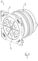
- Figure 1 shows an implementation 1 in an oblique view.
- the bushing 1 has an inverted sleeve 2, discussed in detail below, which is pushed onto a tubular element 20, see also the section Figure 2 .
- the pipe element 20 extends away from a flange plate 3, with which the bushing 1 rests against a formwork when poured into a wall element, see also Figure 3 for illustration.
- the bushing 1 is closed at the end with the flange plate 3 with a closure cover 4. This can be removed after concreting and the actual line can then be laid.
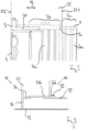
- FIG. 2 the concrete wall element 21 is indicated by dashed lines.
- An inverted section 2a is, based on a longitudinal direction 22 of the line, in the situation according to Figure 2 arranged outside the wall element 21.
- a mounting section 2b of the slip sleeve 2 lies within it.
- the inverting section 2a is also arranged within the wall element 21, namely it is indented inwards.
- the inverting section 2a and the mounting section 2b are connected to one another via a film hinge 2c.
- an inner wall surface 2aa of the inverting section 2a rests on an inner wall surface 2ba of the mounting section 2b. Since the bushing 1 is cast in with the inverted section 2a, a flat formwork element can be placed on both side surfaces 21.1, 21.2 of the wall element, which simplifies the formwork. Small wall thicknesses are also possible.
- a closure (not shown here) can also be inserted into the indented everting section 2a, which covers the bushing 1 in the illustration Figure 2 closed to the right side. This is then removed after pouring and the everting section 2a is turned out.
- a protective tube 31 can then be inserted from the outside of the building 30, namely into the assembly section 2b and thus into the wall element 21.
- the protective tube 31 is thus kept stable even against transverse forces.
- a clamping means 32 is arranged, which presses the everting section 2a onto the protective tube 31.
- the concrete borders the outer wall surface 2bb of the mounting section 2b, with the inserted protective tube 31 also causing an outward pressure and thus a tightness of this interface.
- Figure 4 shows the implementation 1 again in a side view on the outer wall surface 2bb of the mounting section 2b, web seals 40.1-40.3 can be seen, which together form a multi-web seal. This is also pressed towards the outside in a sealing manner by the inserted protective tube 31.
- a circumferential lip 41 can be seen, which rests against a formwork when the bushing 1 is poured.
- a tab 42 can be seen at the end of the everted section 2a, which makes it easier for a fitter to evert it.
- the everting sleeve is provided with a further everting section 2d, which hangs on the mounting section 2b via a film hinge 2e.
- the further everting section 2d can be everted to adapt to a tubular element with a smaller diameter.
- a clamping means can be arranged on the outside of the further everting section 2a in order to fix the everting sleeve 2 relative to the tubular element.
- the sectioned oblique view according to Figure 5 also allows features arranged on the inside to be recognized.
- the sleeve forms a stop 50 up to which the protective tube 31 can be inserted.
- two circumferential elevations 51 are formed on the inner wall surface 2ba in the mounting section 2b, which may be of interest, for example, with regard to a sealing contact with the protective tube 31.
- complementary depressions 52 are provided, in which the elevations 51 come to rest when the everting section 2a is indented.
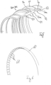
- Figure 6 shows a section of a toothed ring 60, namely from a Figure 5 opposite direction of view, i.e. from the direction from which the protective tube 31 is inserted.
- the toothed ring 60 is arranged in the mounting section 2b on the inside and between the elevations 51.
- the toothed ring 60 is in the present case formed as a punched and bent sheet metal part. It has a large number of teeth 61 all around, along which the protective tube 31 can slide when inserted, but which, when moved in opposite directions, claw into its outer wall surface.
- the toothed ring 60 holds the protective tube 31 in position after insertion, even before the clamping means 32 presses the everting section 2ab onto the protective tube 31.
- the toothed ring 60 can be arranged in the mounting section 2b between the elevations 51, in which case the depressions 52 can also be combined in the inverting section 2a, so the two elevations 51 together with the toothed ring 60 can be placed in a common depression 52.
Landscapes
- Engineering & Computer Science (AREA)
- Architecture (AREA)
- Civil Engineering (AREA)
- Structural Engineering (AREA)
- Forms Removed On Construction Sites Or Auxiliary Members Thereof (AREA)
Priority Applications (2)
| Application Number | Priority Date | Filing Date | Title |
|---|---|---|---|
| EP18213036.9A EP3672003B1 (de) | 2018-12-17 | 2018-12-17 | Verwendung einer durchführung zum eingiessen in ein wandelement |
| PL18213036.9T PL3672003T3 (pl) | 2018-12-17 | 2018-12-17 | Zastosowanie przepustu do zalewania w ściennym elemencie |
Applications Claiming Priority (1)
| Application Number | Priority Date | Filing Date | Title |
|---|---|---|---|
| EP18213036.9A EP3672003B1 (de) | 2018-12-17 | 2018-12-17 | Verwendung einer durchführung zum eingiessen in ein wandelement |
Publications (3)
| Publication Number | Publication Date |
|---|---|
| EP3672003A1 EP3672003A1 (de) | 2020-06-24 |
| EP3672003B1 true EP3672003B1 (de) | 2023-11-22 |
| EP3672003C0 EP3672003C0 (de) | 2023-11-22 |
Family
ID=64744425
Family Applications (1)
| Application Number | Title | Priority Date | Filing Date |
|---|---|---|---|
| EP18213036.9A Active EP3672003B1 (de) | 2018-12-17 | 2018-12-17 | Verwendung einer durchführung zum eingiessen in ein wandelement |
Country Status (2)
| Country | Link |
|---|---|
| EP (1) | EP3672003B1 (pl) |
| PL (1) | PL3672003T3 (pl) |
Citations (2)
| Publication number | Priority date | Publication date | Assignee | Title |
|---|---|---|---|---|
| FR2557388A1 (fr) * | 1983-09-23 | 1985-06-28 | Lebrun Marie Therese | Masque prefabrique et presse-etoupe associes pour passage etanche a travers une paroi |
| DE10007527A1 (de) * | 2000-02-18 | 2001-09-13 | Hauff Technik Gmbh & Co Kg | Dichtpackung zum Hindurchführen von Leitungen durch eine Wand |
Family Cites Families (7)
| Publication number | Priority date | Publication date | Assignee | Title |
|---|---|---|---|---|
| DE2120070A1 (de) * | 1971-04-24 | 1972-11-16 | Beton-Bau Gmbh, 6833 Kirrlach | Wasserdichte Wanddurchführung für elektrische Kabel |
| DE3005144A1 (de) * | 1980-02-12 | 1981-08-20 | Hans 8100 Garmisch-Partenkirchen Langmatz | Mauerdurchfuehrung fuer kabel und leitungen |
| US5941535A (en) * | 1997-05-29 | 1999-08-24 | Richard; James G. | Cast-in-place pipe support having a reversible pipe seal and removable closure disk |
| PL2899332T3 (pl) * | 2014-01-23 | 2016-09-30 | Zastosowanie przepustu do wbudowania w element ściany lub podłogi | |
| CA2945633C (en) * | 2014-03-13 | 2022-08-02 | Hubbell Incorporated | Push to connect weatherproof box |
| EP3061890B1 (de) * | 2015-02-26 | 2017-09-20 | Hauff-Technik GmbH & Co. KG | Durchführung zum Vergießen mit Beton |
| EP3255330B1 (de) * | 2016-06-09 | 2020-02-12 | Hauff-Technik GmbH & Co. KG | Verwendung einer dichthülse |
-
2018
- 2018-12-17 PL PL18213036.9T patent/PL3672003T3/pl unknown
- 2018-12-17 EP EP18213036.9A patent/EP3672003B1/de active Active
Patent Citations (2)
| Publication number | Priority date | Publication date | Assignee | Title |
|---|---|---|---|---|
| FR2557388A1 (fr) * | 1983-09-23 | 1985-06-28 | Lebrun Marie Therese | Masque prefabrique et presse-etoupe associes pour passage etanche a travers une paroi |
| DE10007527A1 (de) * | 2000-02-18 | 2001-09-13 | Hauff Technik Gmbh & Co Kg | Dichtpackung zum Hindurchführen von Leitungen durch eine Wand |
Also Published As
| Publication number | Publication date |
|---|---|
| PL3672003T3 (pl) | 2024-03-04 |
| EP3672003C0 (de) | 2023-11-22 |
| EP3672003A1 (de) | 2020-06-24 |
Similar Documents
| Publication | Publication Date | Title |
|---|---|---|
| EP2899332B1 (de) | Verwendung einer Durchführung zum Einbau in einem Wand- oder Bodenelement | |
| DE19622069A1 (de) | Gehäuse für eine Vorrichtung zur Ausbildung einer Verbindung | |
| EP1288554A1 (de) | Anschlussvorrichtung für ein Rohr | |
| DE102009013066A1 (de) | Bausatz für eine Verbindung eines Inspektions-Schachtes mit einer Abfluss-Leitung | |
| DE69408863T2 (de) | Einsteigeschacht | |
| EP0975914B1 (de) | Verschraubbarer abzweig für dünnwandige kanalrohre | |
| WO2009109386A1 (de) | Verbindungsstück für einen klemmverbinder | |
| EP3672003B1 (de) | Verwendung einer durchführung zum eingiessen in ein wandelement | |
| DE69616381T2 (de) | Klemmvorrichtung | |
| EP3327884B1 (de) | Rohreinführung | |
| EP3288130B1 (de) | Verwendung einer gebäudeeinführung zum einbau in eine gebäudeaussenwand | |
| EP2028740A1 (de) | Einbaudose für elektrische Installationen | |
| DE10034676A1 (de) | Anordnung mit einer Anschlußmuffe und Anschlußmuffe sowie Sohlschale, Öffnungsausbildung und Formkern | |
| DE102018005720B4 (de) | Verwendung einer Durchführung zum Eingießen in eine Bodenplatte | |
| DE19834317A1 (de) | Verfahren zur Sanierung der Sohle von Abwässerschächten | |
| EP0154926A1 (de) | Verfahren zur Herstellung eines Steckanschlusses für Schläuche | |
| EP3061890B1 (de) | Durchführung zum Vergießen mit Beton | |
| DE102015105651A1 (de) | Dichtungselement für einen Lüftungskanal | |
| DE102022124664A1 (de) | Verwendung eines Einsatzes zur Montage in einem Wand- oder Bodenelement | |
| DE69121548T2 (de) | Verbesserte Bandschelle mit keilförmigen, geschlitzten Nocken | |
| EP0104310B1 (de) | Dichtungsring und Muffe mit einem solchen Dichtungsring für eine Rohrsteckverbindung | |
| DE19719969A1 (de) | Verfahren und Vorrichtung zum Sanieren von Hausanschlußbereichen an Abwasserrohren bzw. -kanälen | |
| DE102004040374B4 (de) | Mauerdurchführung | |
| DE102015211773B4 (de) | Dichtmanschette für Leitungsdurchführungen | |
| EP4594663A1 (de) | Verwendung einer elastomerhülse zur montage auf einer leitung |
Legal Events
| Date | Code | Title | Description |
|---|---|---|---|
| PUAI | Public reference made under article 153(3) epc to a published international application that has entered the european phase |
Free format text: ORIGINAL CODE: 0009012 |
|
| STAA | Information on the status of an ep patent application or granted ep patent |
Free format text: STATUS: THE APPLICATION HAS BEEN PUBLISHED |
|
| AK | Designated contracting states |
Kind code of ref document: A1 Designated state(s): AL AT BE BG CH CY CZ DE DK EE ES FI FR GB GR HR HU IE IS IT LI LT LU LV MC MK MT NL NO PL PT RO RS SE SI SK SM TR |
|
| AX | Request for extension of the european patent |
Extension state: BA ME |
|
| STAA | Information on the status of an ep patent application or granted ep patent |
Free format text: STATUS: REQUEST FOR EXAMINATION WAS MADE |
|
| 17P | Request for examination filed |
Effective date: 20201222 |
|
| RBV | Designated contracting states (corrected) |
Designated state(s): AL AT BE BG CH CY CZ DE DK EE ES FI FR GB GR HR HU IE IS IT LI LT LU LV MC MK MT NL NO PL PT RO RS SE SI SK SM TR |
|
| STAA | Information on the status of an ep patent application or granted ep patent |
Free format text: STATUS: EXAMINATION IS IN PROGRESS |
|
| 17Q | First examination report despatched |
Effective date: 20211222 |
|
| 17Q | First examination report despatched |
Effective date: 20220217 |
|
| GRAP | Despatch of communication of intention to grant a patent |
Free format text: ORIGINAL CODE: EPIDOSNIGR1 |
|
| STAA | Information on the status of an ep patent application or granted ep patent |
Free format text: STATUS: GRANT OF PATENT IS INTENDED |
|
| RIC1 | Information provided on ipc code assigned before grant |
Ipc: F16L 5/02 20060101ALN20230624BHEP Ipc: F16L 5/00 20060101ALI20230624BHEP Ipc: H02G 3/22 20060101AFI20230624BHEP |
|
| INTG | Intention to grant announced |
Effective date: 20230707 |
|
| GRAS | Grant fee paid |
Free format text: ORIGINAL CODE: EPIDOSNIGR3 |
|
| GRAA | (expected) grant |
Free format text: ORIGINAL CODE: 0009210 |
|
| STAA | Information on the status of an ep patent application or granted ep patent |
Free format text: STATUS: THE PATENT HAS BEEN GRANTED |
|
| AK | Designated contracting states |
Kind code of ref document: B1 Designated state(s): AL AT BE BG CH CY CZ DE DK EE ES FI FR GB GR HR HU IE IS IT LI LT LU LV MC MK MT NL NO PL PT RO RS SE SI SK SM TR |
|
| REG | Reference to a national code |
Ref country code: GB Ref legal event code: FG4D Free format text: NOT ENGLISH |
|
| REG | Reference to a national code |
Ref country code: CH Ref legal event code: EP Ref country code: DE Ref legal event code: R096 Ref document number: 502018013662 Country of ref document: DE |
|
| REG | Reference to a national code |
Ref country code: IE Ref legal event code: FG4D Free format text: LANGUAGE OF EP DOCUMENT: GERMAN |
|
| U01 | Request for unitary effect filed |
Effective date: 20231123 |
|
| U07 | Unitary effect registered |
Designated state(s): AT BE BG DE DK EE FI FR IT LT LU LV MT NL PT SE SI Effective date: 20231129 |
|
| U20 | Renewal fee for the european patent with unitary effect paid |
Year of fee payment: 6 Effective date: 20240215 |
|
| PG25 | Lapsed in a contracting state [announced via postgrant information from national office to epo] |
Ref country code: GR Free format text: LAPSE BECAUSE OF FAILURE TO SUBMIT A TRANSLATION OF THE DESCRIPTION OR TO PAY THE FEE WITHIN THE PRESCRIBED TIME-LIMIT Effective date: 20240223 |
|
| PG25 | Lapsed in a contracting state [announced via postgrant information from national office to epo] |
Ref country code: IS Free format text: LAPSE BECAUSE OF FAILURE TO SUBMIT A TRANSLATION OF THE DESCRIPTION OR TO PAY THE FEE WITHIN THE PRESCRIBED TIME-LIMIT Effective date: 20240322 |
|
| PG25 | Lapsed in a contracting state [announced via postgrant information from national office to epo] |
Ref country code: ES Free format text: LAPSE BECAUSE OF FAILURE TO SUBMIT A TRANSLATION OF THE DESCRIPTION OR TO PAY THE FEE WITHIN THE PRESCRIBED TIME-LIMIT Effective date: 20231122 |
|
| PG25 | Lapsed in a contracting state [announced via postgrant information from national office to epo] |
Ref country code: IS Free format text: LAPSE BECAUSE OF FAILURE TO SUBMIT A TRANSLATION OF THE DESCRIPTION OR TO PAY THE FEE WITHIN THE PRESCRIBED TIME-LIMIT Effective date: 20240322 Ref country code: GR Free format text: LAPSE BECAUSE OF FAILURE TO SUBMIT A TRANSLATION OF THE DESCRIPTION OR TO PAY THE FEE WITHIN THE PRESCRIBED TIME-LIMIT Effective date: 20240223 Ref country code: ES Free format text: LAPSE BECAUSE OF FAILURE TO SUBMIT A TRANSLATION OF THE DESCRIPTION OR TO PAY THE FEE WITHIN THE PRESCRIBED TIME-LIMIT Effective date: 20231122 |
|
| PG25 | Lapsed in a contracting state [announced via postgrant information from national office to epo] |
Ref country code: RS Free format text: LAPSE BECAUSE OF FAILURE TO SUBMIT A TRANSLATION OF THE DESCRIPTION OR TO PAY THE FEE WITHIN THE PRESCRIBED TIME-LIMIT Effective date: 20231122 Ref country code: NO Free format text: LAPSE BECAUSE OF FAILURE TO SUBMIT A TRANSLATION OF THE DESCRIPTION OR TO PAY THE FEE WITHIN THE PRESCRIBED TIME-LIMIT Effective date: 20240222 Ref country code: HR Free format text: LAPSE BECAUSE OF FAILURE TO SUBMIT A TRANSLATION OF THE DESCRIPTION OR TO PAY THE FEE WITHIN THE PRESCRIBED TIME-LIMIT Effective date: 20231122 |
|
| PG25 | Lapsed in a contracting state [announced via postgrant information from national office to epo] |
Ref country code: SK Free format text: LAPSE BECAUSE OF FAILURE TO SUBMIT A TRANSLATION OF THE DESCRIPTION OR TO PAY THE FEE WITHIN THE PRESCRIBED TIME-LIMIT Effective date: 20231122 |
|
| PG25 | Lapsed in a contracting state [announced via postgrant information from national office to epo] |
Ref country code: SM Free format text: LAPSE BECAUSE OF FAILURE TO SUBMIT A TRANSLATION OF THE DESCRIPTION OR TO PAY THE FEE WITHIN THE PRESCRIBED TIME-LIMIT Effective date: 20231122 Ref country code: SK Free format text: LAPSE BECAUSE OF FAILURE TO SUBMIT A TRANSLATION OF THE DESCRIPTION OR TO PAY THE FEE WITHIN THE PRESCRIBED TIME-LIMIT Effective date: 20231122 Ref country code: RO Free format text: LAPSE BECAUSE OF FAILURE TO SUBMIT A TRANSLATION OF THE DESCRIPTION OR TO PAY THE FEE WITHIN THE PRESCRIBED TIME-LIMIT Effective date: 20231122 |
|
| REG | Reference to a national code |
Ref country code: DE Ref legal event code: R097 Ref document number: 502018013662 Country of ref document: DE |
|
| PG25 | Lapsed in a contracting state [announced via postgrant information from national office to epo] |
Ref country code: MC Free format text: LAPSE BECAUSE OF FAILURE TO SUBMIT A TRANSLATION OF THE DESCRIPTION OR TO PAY THE FEE WITHIN THE PRESCRIBED TIME-LIMIT Effective date: 20231122 |
|
| PG25 | Lapsed in a contracting state [announced via postgrant information from national office to epo] |
Ref country code: MC Free format text: LAPSE BECAUSE OF FAILURE TO SUBMIT A TRANSLATION OF THE DESCRIPTION OR TO PAY THE FEE WITHIN THE PRESCRIBED TIME-LIMIT Effective date: 20231122 |
|
| PLBE | No opposition filed within time limit |
Free format text: ORIGINAL CODE: 0009261 |
|
| STAA | Information on the status of an ep patent application or granted ep patent |
Free format text: STATUS: NO OPPOSITION FILED WITHIN TIME LIMIT |
|
| REG | Reference to a national code |
Ref country code: IE Ref legal event code: MM4A |
|
| PG25 | Lapsed in a contracting state [announced via postgrant information from national office to epo] |
Ref country code: IE Free format text: LAPSE BECAUSE OF NON-PAYMENT OF DUE FEES Effective date: 20231217 |
|
| 26N | No opposition filed |
Effective date: 20240823 |
|
| PG25 | Lapsed in a contracting state [announced via postgrant information from national office to epo] |
Ref country code: IE Free format text: LAPSE BECAUSE OF NON-PAYMENT OF DUE FEES Effective date: 20231217 |
|
| U20 | Renewal fee for the european patent with unitary effect paid |
Year of fee payment: 7 Effective date: 20241219 |
|
| PGFP | Annual fee paid to national office [announced via postgrant information from national office to epo] |
Ref country code: CH Payment date: 20250101 Year of fee payment: 7 |
|
| PG25 | Lapsed in a contracting state [announced via postgrant information from national office to epo] |
Ref country code: CY Free format text: LAPSE BECAUSE OF FAILURE TO SUBMIT A TRANSLATION OF THE DESCRIPTION OR TO PAY THE FEE WITHIN THE PRESCRIBED TIME-LIMIT; INVALID AB INITIO Effective date: 20181217 |
|
| PG25 | Lapsed in a contracting state [announced via postgrant information from national office to epo] |
Ref country code: HU Free format text: LAPSE BECAUSE OF FAILURE TO SUBMIT A TRANSLATION OF THE DESCRIPTION OR TO PAY THE FEE WITHIN THE PRESCRIBED TIME-LIMIT; INVALID AB INITIO Effective date: 20181217 |
|
| PG25 | Lapsed in a contracting state [announced via postgrant information from national office to epo] |
Ref country code: TR Free format text: LAPSE BECAUSE OF FAILURE TO SUBMIT A TRANSLATION OF THE DESCRIPTION OR TO PAY THE FEE WITHIN THE PRESCRIBED TIME-LIMIT Effective date: 20231122 |
|
| REG | Reference to a national code |
Ref country code: CH Ref legal event code: U11 Free format text: ST27 STATUS EVENT CODE: U-0-0-U10-U11 (AS PROVIDED BY THE NATIONAL OFFICE) Effective date: 20260101 |
|
| PGFP | Annual fee paid to national office [announced via postgrant information from national office to epo] |
Ref country code: GB Payment date: 20251216 Year of fee payment: 8 |
|
| PGFP | Annual fee paid to national office [announced via postgrant information from national office to epo] |
Ref country code: CZ Payment date: 20251204 Year of fee payment: 8 |
|
| U20 | Renewal fee for the european patent with unitary effect paid |
Year of fee payment: 8 Effective date: 20251216 |
|
| PGFP | Annual fee paid to national office [announced via postgrant information from national office to epo] |
Ref country code: PL Payment date: 20251209 Year of fee payment: 8 |