EP3671991B1 - Dreiphasige schaltanlage - Google Patents
Dreiphasige schaltanlage Download PDFInfo
- Publication number
- EP3671991B1 EP3671991B1 EP18214214.1A EP18214214A EP3671991B1 EP 3671991 B1 EP3671991 B1 EP 3671991B1 EP 18214214 A EP18214214 A EP 18214214A EP 3671991 B1 EP3671991 B1 EP 3671991B1
- Authority
- EP
- European Patent Office
- Prior art keywords
- compartment
- cable connection
- switchgear
- components
- door
- Prior art date
- Legal status (The legal status is an assumption and is not a legal conclusion. Google has not performed a legal analysis and makes no representation as to the accuracy of the status listed.)
- Active
Links
Images

Classifications
-
- H—ELECTRICITY
- H02—GENERATION; CONVERSION OR DISTRIBUTION OF ELECTRIC POWER
- H02B—BOARDS, SUBSTATIONS OR SWITCHING ARRANGEMENTS FOR THE SUPPLY OR DISTRIBUTION OF ELECTRIC POWER
- H02B13/00—Arrangement of switchgear in which switches are enclosed in, or structurally associated with, a casing, e.g. cubicle
- H02B13/02—Arrangement of switchgear in which switches are enclosed in, or structurally associated with, a casing, e.g. cubicle with metal casing
-
- H—ELECTRICITY
- H02—GENERATION; CONVERSION OR DISTRIBUTION OF ELECTRIC POWER
- H02B—BOARDS, SUBSTATIONS OR SWITCHING ARRANGEMENTS FOR THE SUPPLY OR DISTRIBUTION OF ELECTRIC POWER
- H02B13/00—Arrangement of switchgear in which switches are enclosed in, or structurally associated with, a casing, e.g. cubicle
- H02B13/02—Arrangement of switchgear in which switches are enclosed in, or structurally associated with, a casing, e.g. cubicle with metal casing
- H02B13/025—Safety arrangements, e.g. in case of excessive pressure or fire due to electrical defect
Definitions
- the present invention relates to a three phase switchgear for low voltage, medium voltage or high voltage use within a substation.
- switchgear and control gear also called controlgear
- main circuits and auxiliary circuit are arranged in a manner that is not convenient for monitoring or maintenance.
- US 2017/0085064 A1 describes a local equipment room (LER) for use in an industrial facility, having one or more robots to perform certain tasks, and the LER being filled with non-atmospheric fluid or gas.
- DE4103101A1 describes that the drive shaft is provided for operating at least one knife switch.
- the earth connection is fixed on or at an insulating part, also the support part, the fixed contact and the bearing for the drive shaft, and that the insulating part can be made of synthetic resin.
- the support part the fixed contact, the bearing and the earth connection, at least two are arranged at the insulating support part.
- the support part, the fixed contact and the earthing connection are cast integral at the moulded insualting support part.
- CN104577747A relates to a switch cabinet integrated to a modular smart power grid.
- the switch cabinet comprises a cabinet body which consists of an upper cabinet body and a lower cabinet body as well as a relay instrument room, an isolating switch operating mechanism, a circuit breaker operating mechanism and a lower cabinet door which are sequentially arranged at the front end of the cabinet body from bottom to top, wherein two opposite side plates are arranged on two sides of the lower cabinet body; an edgefold which is bent towards the interior of the cabinet body is arranged at the upper end of each of the side plates; edgefold mounting holes are formed in each of the edgefolds; an insulating mounting frame is fixedly mounted on the edgefolds, the insulating mounting frame consists of a front end plate, a rear end plate, an inlet wire insulating supporting piece, a left side plate and a right side plate; an isolating switch and a circuit breaker are mounted on the insulating mounting frame; a current transformer and a lightning arrester are further sequentially arranged from top to bottom below the circuit breaker in the lower cabinet body.
- EP2953219A1 describes that a pressure tank in which a circuit breaker and a disconnector are received and an insulating gas is sealed, a circuit breaker operating mechanism that is installed outside the pressure tank and operates the circuit breaker, and a disconnector operating mechanism that is installed outside the pressure tank and operates the disconnector form an integrated structure and are received in a housing.
- the integrated structure is rotated and positioned in accordance with positions of bus-connecting portions for buses, which are connected to the pressure tank, and a position of an external cable-connecting portion for an external cable.
- CN103996990A describes an inflatable switch cabinet which comprises a cabinet body.
- a gas tank is arranged on the rear side of the cabinet body, a control chamber is arranged on the upper portion of the front side of the cabinet body, a cable chamber is arranged on the lower portion of the front side of the cabinet body, a vacuum breaker is arranged on the upper portion of the gas tank, an isolating switch is arranged in the middle of the gas tank, a main loop is arranged on the lower portion of the gas tank, and an isolating switch operating mechanism and a vacuum breaker operating mechanism are arranged in the control chamber.
- the isolating switch operating mechanism achieves switch-on, switch-off and ground connection of a disconnecting link by operating a first operating shaft and a second operating shaft, and power-driven operation can be achieved.
- the vacuum breaker comprises an insulation support, a vacuum bubble and an operating main shaft, the vacuum bubble is arranged in the insulation support in the mode with an upward dynamic contact, a conductive contact and a conductive piece are fixedly arranged on the lower portion of the insulation support and are fixedly connected with a static contact at the lower end of the vacuum bubble, the conductive contact and the disconnecting link are matched for switch-on, and the operating main shaft drives the dynamic contact at the upper end of the vacuum bubble to vertically move to achieve switch-on and switch-off of the vacuum breaker. It is described that the inflatable switch cabinet is compact in structure, reliable in motion, safe in use and convenient to maintain.
- CN206595617U describes a gas insulated switch device, including the cabinet body, internal portion is equipped with low -pressure chamber, switch gear room, operation mechanism chamber, cable chamber and pressure release room at the cabinet, switch gear room and cabinet body fixed connection, and operation mechanism chamber sets up between switch gear room and cabinet door, and the low -pressure chamber setting is in the operation mechanism chamber top, and the cable chamber setting is in the operation mechanism chamber below, and the pressure release room sets up in the switch gear room below, the switch gear room includes inclosed gas tank, expands generating line, vacuum circuit breaker and isolator from last to being equipped with the side down in proper order in that the gas tank is inside, is equipped with the connection bar copper at the lower extreme of gas tank, and the other end of connection bar copper is connected with the cable chamber for electric wire between protective bonding switch gear room and the cable chamber, be equipped with vacuum circuit breaker operating device and isolating switch operating device under to in proper order on the operation mechanism chamber follow.
- the utility model provides a gas insulated switch device is that modularized design,
- the vacuum switch ring main unit suitable comprises a ring main unit body, wherein the ring main unit body is divided into an operating chamber, a vacuum switch chamber, a cable chamber and a gas discharge chamber; the vacuum switch chamber is internally provided with a plurality of vacuum circuit breakers, isolating switches, conductive rods, and a first transmission shaft and a third transmission shaft which are vertical to the vacuum circuit breakers; the plurality of isolating switches are fixedly connected through the third transmission shaft, and the isolating switches are connected with the conductive rods respectively; a cam mechanism is fixed to each end of the first transmission shaft, and the cam mechanisms are in contact with a second transmission shaft and drive the second transmission shaft to move up and down; the operating chamber is integrally provided with a first operating mechanism which is used for controlling the first transmission shaft to rotate, and a second operating mechanism which is used for controlling the third transmission shaft to rotate; and a first rotating shaft drives
- Such robotic systems operate with the substation or switchgear or control gear and perform both monitoring and maintenance tasks.
- Such robotic systems can be quite complex and expensive, especially when considering variability existing in substations today.
- robotic systems can reduce maintenance tasks in a substation with respect to switchgear or control gear, the robot itself may require considerable maintenance. This can require the robot to be removed from the substation, switchgear or control gear or the personnel entering the substation, switchgear or control gear and thus leads to substation shut down.
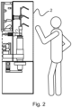
- Figs. 1-2 show examples of a switchgear for operation in a low voltage, medium voltage or high voltage substation.
- a human operator is shown to the right of the switchgear, but they could equally be on the left gaining access to the components accessible from that side of the switchgear or control panel. It is to be noted that the example shown in Fig. 1 relates to the claimed switchgear.
- One example relates to a switchgear, comprising at least one first compartment 2, 8, 12, a second compartment 1, a plurality of main switchgear components, and a plurality of auxiliary switchgear components.
- the plurality of main switchgear components comprises a main busbar system 3, a three position linear or rotational movement disconnector 4, a circuit breaker 5, and a cable connection.
- the plurality of auxiliary switchgear components comprises a disconnector drive 11 and a circuit breaker drive 10.
- the plurality of main switchgear components are housed in the at least one first compartment.
- the plurality of auxiliary switchgear are housed in the second compartment.
- the circuit breaker and three position linear or rotational movement disconnector are mounted vertically one above the other in the at least one first compartment.
- Figs. 1-2 could relate to one phase of a three phase system, and the components for the other two phases could similarly be housed in the at least one first compartment and the second compartment.
- auxiliary components for all three phases can be in the second compartment, and the main or primary components for all three phases be located in the at least one first compartment, but with the circuit breaker and disconnector for each mounted vertically.
- the description below can also relate to a three phase system, where the description as it relates to one phase could apply to all three phases.
- segregating walls can be provided between components relating to the different phases.
- the circuit breaker and three position or rotational movement disconnector are mounted vertically one above the other in the at least one first compartment.
- the at least one first compartment is configured to enable an operator to access an interior of the at least one first compartment.
- the disconnector drive 11 and the circuit breaker drive 10 are mounted vertically one above the other in the second compartment.
- the at least one first compartment comprises two compartments 8, 12.
- a first compartment 8 of the at least one first compartment is a cable connection compartment within which is housed a cable connection.
- a second compartment 12 of the at least one first compartment houses the circuit breaker and the three position linear or rotational movement disconnector.
- a voltage sensor 9 and a current sensor 6 are housed in the cable connection compartment.
- At least one sensor is located in the cable connection compartment 8, and the at least one sensor is configured to monitor the components in the cable connection compartment.
- At least one sensor is located in the second compartment 12 of the at least one first compartment, and the at least one sensor is configured to monitor the components in the second compartment of the at least one first compartment.
- the second compartment is open-sided on at least one side.
- the at least one first compartment comprises at least one door or removable wall section.
- a door or removable wall section 7 is located in a wall segregating the cable connection compartment 8 from the second compartment 12 of the at least one first compartment.
- the switchgear is configured such that the door or removable wall section 7 must be in position to provide an arc proof segregation between the cable connection compartment and the second compartment of the at least one first compartment for a user to be able to at least partially enter the cable connection compartment when the components in the second compartment of the at least one first compartment are energized.
- the door is configured to operate automatically.
- the cable connection compartment has at least one door or removal wall section in an exterior wall.
- the second compartment 12 of the at least one first compartment has at least one door or removal wall section in an exterior wall.
- the second compartment of the at least one first compartment is sized such that a user can gain access to the interior of the second compartment of the at least one first compartment without being able to completely enter the second compartment of the at least one first compartment.
- At least one sensor is located in the second compartment 1, and the at least one sensor is configured to monitor the components in the second compartment.
- one or more of the plurality of auxiliary switchgear or control components are housed in a removable module within the second compartment.
- switchgear has been designed allowing for a much simpler automation system to be designed for monitoring and maintenance tasks on the unmanned switchgear.
- components and switching devices on the primary circuit are arranged vertically, and could be one above the other, to facilitate better access to them for monitoring and maintenance, and can be arranged vertically, and in one plane if required.
- the auxiliaries of the switching devices can also be arranged vertically, and again one above the other as well, in one vertical plane if required.
- the auxiliaries are separated from the primary circuits by an arc proof wall to allow for human personnel access whilst the switchgear is in operation.
- a removable cover is provided in front of the switching devices auxiliaries. This facilitates maintenance of auxiliaries, via automation systems or humans, that may require more frequent maintenance than other components within the switchgear.
- Fig. 1 shows a detailed example of a switchgear, where for ease of reference the following features shown are listed:
- the primary circuits and devices are located in one common busbar and circuit breaker compartment 12, that can be opened and need not be segregated feeder by feeder with side walls, but can be segregated feeder by feeder with side walls. Any arc fault situation is preferably mitigated by active arc fault protection, and the arc duration limited to a level that does not allow the arc to burn uncontrollably.
- the cable compartment 8 of each feeder is in normal operation opened to the common busbar and circuit breaker compartment 12, while an automatically operated arc proof segregation is inserted to segregate the cable connection compartment from the rest of the switchgear in case a human operator needs to access to cable connections of a particular feeder.
- the cable compartments are segregated between feeders with side walls, but this is not essential.
- the main busbar and circuit breaker space 12 is provided with an automation system that moves along the feeder line and monitors and/or maintains the switching devices, insulation, and joints on the primary circuit.
- the low-voltage compartment 1 can have at least one open side, but can be enclosed with walls that are removable.
- the auxiliaries of the switching devices are modularised in order to simplify maintenance tasks on the auxiliaries, through extracting a removable module from the low-voltage compartment housing the auxiliaries. Then either carrying out maintenance or repair on the auxiliaries and reinserting the same module, or immediately replacing the module with a module housing the same auxiliaries and then later carrying out maintenance or repair on the auxiliaries in the module that was first extracted.
- a door or removable cover separates the cable connection compartment 8 from the main circuit compartment 12.
- One or more fixed sensors can be installed in each compartment for monitoring, however such monitoring and maintenance tasks can be carried out by human operators.
- the switchgear can have a design where the depth of the common main busbar and circuit breaker compartment 12 has been shrunk to a minimum, while still enabling the human operator to access the interior via a removable cover or door.
- a circuit breaker pole design of the switchgear can have primary connections on the pole side, instead of the pole having top and bottom primary connections.
- the primary connections on such a pole can then face the main compartment space 12, thereby facilitating access by an automation system.
- Fig.1 a rotational three position disconnector switch is shown, but a disconnector switch with linear movement can be used instead.
- the primary circuit can include other components and devices not described in Fig.1 , such as earthing switch, voltage indication, surge arrestors, Ultra Fast Earthing Switch (UFES), IS-limiters (as invented by ABB Calor Emag in 1955), contactors, load-break switches, fuses.
- Fig.1 earthing switch, voltage indication, surge arrestors, Ultra Fast Earthing Switch (UFES), IS-limiters (as invented by ABB Calor Emag in 1955), contactors, load-break switches, fuses.
Landscapes
- Engineering & Computer Science (AREA)
- Power Engineering (AREA)
- Patch Boards (AREA)
- Switch Cases, Indication, And Locking (AREA)
- Gas-Insulated Switchgears (AREA)
Claims (9)
- Eine Schaltanlage, umfassend:- mindestens ein erstes Fach (2, 8, 12);- ein zweites Fach (1);- eine Vielzahl von Hauptschaltanlagenkomponenten; und- eine Vielzahl von Hilfsschaltanlagenkomponenten;wobei das mindestens eine erste Fach mindestens eine Tür oder eine entfernbare Wandsektion umfasst,wobei das mindestens eine erste Fach lichtbogenfest ausgeführt ist,wobei die Vielzahl der Hauptschaltanlagenkomponenten ein Hauptsammelschienensystem (3), einen dreistufigen linearen oder rotierenden Trennschalter (4), einen Leistungsschalter (5) und eine Kabelverbindung umfasst,wobei die Vielzahl der Hilfsschaltanlagenkomponenten einen Trennschalterantrieb (11) und einen Leistungsschalterantrieb (10) umfasst,wobei die Vielzahl der Hauptschaltanlagenkomponenten im mindestens einen ersten Fach untergebracht ist,wobei die Vielzahl der Hilfsschaltanlagenkomponenten im zweiten Fach untergebracht ist,wobei der Leistungsschalter und der dreistufige lineare oder rotierende Trennschalter vertikal übereinander im mindestens einen ersten Fach montiert sind,wobei der Trennschalterantrieb (11) und der Leistungsschalterantrieb (10) vertikal übereinander im zweiten Fach montiert sind,wobei das mindestens eine erste Fach zwei Fächer (8, 12) umfasst, wobei ein erstes Fach (8) des mindestens einen ersten Fachs ein Kabelanschlussfach ist, in dem eine Kabelverbindung untergebracht ist, und wobei ein zweites Fach (12) des mindestens einen ersten Fachs den Leistungsschalter und den dreistufigen linearen oder rotierenden Trennschalter beherbergt,wobei eine Tür (7) in einer Wand angeordnet ist, die das Kabelanschlussfach (8) von dem zweiten Fach (12) des mindestens einen ersten Fachs trennt,wobei das Kabelanschlussfach (8) eine Tür oder eine entfernbare Wandsektion in einer Außenwand aufweist,wobei die Tür (7), die sich in der Wand befindet, die das Kabelanschlussfach (8) von dem zweiten Fach (12) des mindestens einen ersten Fachs trennt, so konfiguriert ist, dass sie geöffnet ist, wenn eine Einspeisung in Betrieb ist, und die Tür oder entfernbare Wandsektion in der Außenwand des Kabelanschlussfachs geschlossen ist,und wobei die Tür (7), die sich in der Wand befindet, die das Kabelanschlussfach (8) von dem zweiten Fach (12) des mindestens einen ersten Fachs trennt, so konfiguriert ist, dass sie sich automatisch schließt, wenn die Tür oder entfernbare Wandsektion in der Außenwand des Kabelanschlussfachs für den Zugang durch Personen geöffnet wird, sodass die Tür (7), die sich in der Wand befindet, die das Kabelanschlussfach (8) von dem zweiten Fach (12) des mindestens einen ersten Fachs trennt, zusammen mit der Wand des Kabelanschlussfachs eine lichtbogenfeste Trennung zwischen dem Kabelanschlussfach (8) und dem zweiten Fach (12) des mindestens einen ersten Fachs bildet, wenn sie sich in der geschlossenen Position befindet, wodurch es einem Benutzer ermöglicht wird, das Kabelanschlussfach zumindest teilweise zu betreten, während die Komponenten im zweiten Fach (12) des mindestens einen ersten Fachs unter Spannung stehen.
- Schaltanlage nach Anspruch 1, wobei, wenn die Vielzahl der Hauptschaltanlagenkomponenten spannungslos ist, das mindestens eine erste Fach so konfiguriert ist, dass es einem Bediener den Zugang zum Innenraum des mindestens einen ersten Fachs ermöglicht.
- Schaltanlage nach einem der Ansprüche 1-2, wobei ein Spannungssensor (9) und ein Stromsensor (6) im Kabelanschlussfach untergebracht sind.
- Schaltanlage nach einem der Ansprüche 1-3, wobei mindestens ein Sensor im Kabelanschlussfach (8) angeordnet ist und wobei der mindestens eine Sensor eingerichtet ist, die Komponenten im Kabelanschlussfach zu überwachen.
- Schaltanlage nach einem der Ansprüche 1-4, wobei mindestens ein Sensor im zweiten Fach (12) des mindestens einen ersten Fachs angeordnet ist und wobei der mindestens eine Sensor eingerichtet ist, die Komponenten im zweiten Fach des mindestens einen ersten Fachs zu überwachen.
- Schaltanlage nach einem der Ansprüche 1-5, wobei das zweite Fach auf mindestens einer Seite offen ist.
- Schaltanlage nach einem der Ansprüche 1-6, wobei das zweite Fach des mindestens einen ersten Fachs so dimensioniert ist, dass ein Benutzer Zugang zum Innenraum des zweiten Fachs des mindestens einen ersten Fachs erhalten kann, ohne das zweite Fach des mindestens einen ersten Fachs vollständig betreten zu können.
- Schaltanlage nach einem der Ansprüche 1-7, wobei mindestens ein Sensor im zweiten Fach (1) angeordnet ist und wobei der mindestens eine Sensor eingerichtet ist, die Komponenten im zweiten Fach zu überwachen.
- Schaltanlage nach einem der Ansprüche 1-8, wobei eine oder mehrere der Vielzahl der Hilfsschaltanlagenkomponenten in einem herausnehmbaren Modul innerhalb des zweiten Fachs untergebracht sind.
Priority Applications (4)
| Application Number | Priority Date | Filing Date | Title |
|---|---|---|---|
| EP18214214.1A EP3671991B1 (de) | 2018-12-19 | 2018-12-19 | Dreiphasige schaltanlage |
| PCT/EP2019/084673 WO2020126747A1 (en) | 2018-12-19 | 2019-12-11 | Three phase switchgear or control gear |
| CN201980084650.XA CN113196603B (zh) | 2018-12-19 | 2019-12-11 | 三相开关机构或控制机构 |
| US17/345,067 US11670919B2 (en) | 2018-12-19 | 2021-06-11 | Three phase switchgear or control gear |
Applications Claiming Priority (1)
| Application Number | Priority Date | Filing Date | Title |
|---|---|---|---|
| EP18214214.1A EP3671991B1 (de) | 2018-12-19 | 2018-12-19 | Dreiphasige schaltanlage |
Publications (2)
| Publication Number | Publication Date |
|---|---|
| EP3671991A1 EP3671991A1 (de) | 2020-06-24 |
| EP3671991B1 true EP3671991B1 (de) | 2025-04-23 |
Family
ID=64755143
Family Applications (1)
| Application Number | Title | Priority Date | Filing Date |
|---|---|---|---|
| EP18214214.1A Active EP3671991B1 (de) | 2018-12-19 | 2018-12-19 | Dreiphasige schaltanlage |
Country Status (4)
| Country | Link |
|---|---|
| US (1) | US11670919B2 (de) |
| EP (1) | EP3671991B1 (de) |
| CN (1) | CN113196603B (de) |
| WO (1) | WO2020126747A1 (de) |
Families Citing this family (1)
| Publication number | Priority date | Publication date | Assignee | Title |
|---|---|---|---|---|
| EP3671989B1 (de) * | 2018-12-19 | 2025-08-13 | ABB Schweiz AG | Dreiphasen-schaltanlage mit einphasiger ausrüstung in einem gehäuse |
Citations (3)
| Publication number | Priority date | Publication date | Assignee | Title |
|---|---|---|---|---|
| CN103996990A (zh) * | 2014-05-29 | 2014-08-20 | 厦门兴厦控电气有限公司 | 一种新型充气开关柜 |
| CN105071280A (zh) * | 2015-08-21 | 2015-11-18 | 亚洲电力设备(深圳)股份有限公司 | 适用于环保气体绝缘型的真空开关环网柜 |
| CN206595617U (zh) * | 2017-03-01 | 2017-10-27 | 珠海康晋电气股份有限公司 | 一种气体绝缘开关设备 |
Family Cites Families (25)
| Publication number | Priority date | Publication date | Assignee | Title |
|---|---|---|---|---|
| DE4103101C3 (de) * | 1990-03-22 | 1996-08-14 | Mitsubishi Electric Corp | Trennschalter, sowie Druckgas-isoliertes Schaltgetriebe mit solchem |
| JP2001352621A (ja) * | 2000-06-02 | 2001-12-21 | Mitsubishi Electric Corp | ガス絶縁開閉装置 |
| JP4193099B2 (ja) * | 2002-07-31 | 2008-12-10 | 富士電機システムズ株式会社 | ガス絶縁開閉装置 |
| JP2004187348A (ja) * | 2002-11-29 | 2004-07-02 | Mitsubishi Electric Corp | ガス絶縁開閉装置 |
| JP4400089B2 (ja) * | 2003-05-08 | 2010-01-20 | 富士電機システムズ株式会社 | 密閉形ガス絶縁開閉装置 |
| JP2005304200A (ja) * | 2004-04-13 | 2005-10-27 | Nissin Electric Co Ltd | ガス絶縁開閉装置 |
| CN103368085B (zh) * | 2013-05-28 | 2016-03-30 | 环宇集团(南京)有限公司 | 一种铠装移开式交流金属封闭开关设备 |
| JP5638726B1 (ja) * | 2014-04-29 | 2014-12-10 | 三菱電機株式会社 | ガス絶縁スイッチギヤ |
| CN204333720U (zh) * | 2014-11-10 | 2015-05-13 | 南通大洋电力设备有限公司 | 开关柜 |
| CN204216476U (zh) * | 2014-11-28 | 2015-03-18 | 湖南长高高压开关集团股份公司 | 一种模块化智能箱型固定充气式高压交流金属封闭开关设备 |
| CN104577747B (zh) * | 2014-12-10 | 2017-02-22 | 江苏德春电力科技股份有限公司 | 集成于模块化智能电网的开关柜 |
| CN204577866U (zh) * | 2015-03-04 | 2015-08-19 | 国家电网公司 | 一种防电弧引发母线短路的成套配电装置及其触头盒 |
| WO2017048350A1 (en) | 2015-09-18 | 2017-03-23 | Exxonmobil Upstream Research Company | Electrical room provided with a robot |
| CN106159776A (zh) * | 2016-08-11 | 2016-11-23 | 现代重工(中国)电气有限公司 | 一种hms12金属铠装移开式开关柜 |
| US10305262B2 (en) * | 2016-09-26 | 2019-05-28 | Bethel Idiculla Johnson | Medium voltage switchgear enclosure |
| CN108666923A (zh) * | 2017-03-27 | 2018-10-16 | 浙宝电气(杭州)集团有限公司 | 环保气体绝缘交流金属封闭开关柜 |
| WO2018229962A1 (ja) * | 2017-06-16 | 2018-12-20 | 三菱電機株式会社 | ガス絶縁開閉装置 |
| EP3422503A1 (de) | 2017-06-28 | 2019-01-02 | ABB Schweiz AG | Ein interner roboter-manipulator für unbemannte betriebs- und wartungsarbeiten bei ausfahbarer leistungsschaltern und ein verfahren zum betreiben des roboter-manipulators |
| EP3421190B1 (de) | 2017-06-28 | 2022-05-04 | ABB Schweiz AG | Schaltgerät mit unbemannter bedienung und wartung sowie verfahren zum betrieb davon |
| EP3422502B1 (de) * | 2017-06-28 | 2021-04-07 | ABB Schweiz AG | Unterstation für mittel- oder hochspannung mit schaltgerät oder steuergerät mit unbemannter operation und wartung |
| CN110832720B (zh) | 2017-06-28 | 2022-06-24 | Abb瑞士股份有限公司 | 包含无人操作和维护的开关装置或控制装置的变电站 |
| CN112154581B (zh) * | 2018-05-24 | 2022-04-08 | 三菱电机株式会社 | 气体绝缘开闭装置 |
| EP3671988A1 (de) * | 2018-12-19 | 2020-06-24 | ABB Schweiz AG | Hermetischgasdichte schaltanlage mit einem einzelnes fach für leistungsschalter, trennschalter mit dreipositionen und hauptbusschiene. |
| EP3671986B1 (de) * | 2018-12-19 | 2025-05-14 | ABB Schweiz AG | Schaltanlage |
| EP3671989B1 (de) * | 2018-12-19 | 2025-08-13 | ABB Schweiz AG | Dreiphasen-schaltanlage mit einphasiger ausrüstung in einem gehäuse |
-
2018
- 2018-12-19 EP EP18214214.1A patent/EP3671991B1/de active Active
-
2019
- 2019-12-11 WO PCT/EP2019/084673 patent/WO2020126747A1/en not_active Ceased
- 2019-12-11 CN CN201980084650.XA patent/CN113196603B/zh active Active
-
2021
- 2021-06-11 US US17/345,067 patent/US11670919B2/en active Active
Patent Citations (3)
| Publication number | Priority date | Publication date | Assignee | Title |
|---|---|---|---|---|
| CN103996990A (zh) * | 2014-05-29 | 2014-08-20 | 厦门兴厦控电气有限公司 | 一种新型充气开关柜 |
| CN105071280A (zh) * | 2015-08-21 | 2015-11-18 | 亚洲电力设备(深圳)股份有限公司 | 适用于环保气体绝缘型的真空开关环网柜 |
| CN206595617U (zh) * | 2017-03-01 | 2017-10-27 | 珠海康晋电气股份有限公司 | 一种气体绝缘开关设备 |
Also Published As
| Publication number | Publication date |
|---|---|
| EP3671991A1 (de) | 2020-06-24 |
| WO2020126747A1 (en) | 2020-06-25 |
| CN113196603B (zh) | 2024-02-13 |
| US11670919B2 (en) | 2023-06-06 |
| US20210305789A1 (en) | 2021-09-30 |
| CN113196603A (zh) | 2021-07-30 |
Similar Documents
| Publication | Publication Date | Title |
|---|---|---|
| RU2344529C2 (ru) | Газоизолированное распределительное устройство с закрытыми ячейками | |
| US6242708B1 (en) | Isolator switch | |
| US8481881B2 (en) | Electric circuit breaker and switchgear panel with circuit breaker | |
| JP4268991B2 (ja) | 真空絶縁スイッチギヤ | |
| EP3671986B1 (de) | Schaltanlage | |
| EP3671989B1 (de) | Dreiphasen-schaltanlage mit einphasiger ausrüstung in einem gehäuse | |
| US11139642B2 (en) | Switchgear or control gear | |
| US11005240B2 (en) | Three phase switchgear or control gear | |
| CN1007769B (zh) | 具有分成封闭间隔的金属铠装配电装置 | |
| EP3671991B1 (de) | Dreiphasige schaltanlage | |
| KR100356512B1 (ko) | 가스 절연 배전반 | |
| RU214797U1 (ru) | Шкаф комплектного распределительного устройства | |
| CN111755279A (zh) | 用于配电网的气体绝缘的电气开关设备 | |
| RU26692U1 (ru) | Шкаф устройств комплектных распределительных типа кру | |
| CN105305288A (zh) | 具有分成封闭间隔的金属铠装配电装置 | |
| CZ11978U1 (cs) | Dvousystémová kobková rozvodna |
Legal Events
| Date | Code | Title | Description |
|---|---|---|---|
| PUAI | Public reference made under article 153(3) epc to a published international application that has entered the european phase |
Free format text: ORIGINAL CODE: 0009012 |
|
| STAA | Information on the status of an ep patent application or granted ep patent |
Free format text: STATUS: THE APPLICATION HAS BEEN PUBLISHED |
|
| AK | Designated contracting states |
Kind code of ref document: A1 Designated state(s): AL AT BE BG CH CY CZ DE DK EE ES FI FR GB GR HR HU IE IS IT LI LT LU LV MC MK MT NL NO PL PT RO RS SE SI SK SM TR |
|
| AX | Request for extension of the european patent |
Extension state: BA ME |
|
| STAA | Information on the status of an ep patent application or granted ep patent |
Free format text: STATUS: REQUEST FOR EXAMINATION WAS MADE |
|
| 17P | Request for examination filed |
Effective date: 20201130 |
|
| RBV | Designated contracting states (corrected) |
Designated state(s): AL AT BE BG CH CY CZ DE DK EE ES FI FR GB GR HR HU IE IS IT LI LT LU LV MC MK MT NL NO PL PT RO RS SE SI SK SM TR |
|
| STAA | Information on the status of an ep patent application or granted ep patent |
Free format text: STATUS: EXAMINATION IS IN PROGRESS |
|
| 17Q | First examination report despatched |
Effective date: 20210802 |
|
| GRAP | Despatch of communication of intention to grant a patent |
Free format text: ORIGINAL CODE: EPIDOSNIGR1 |
|
| STAA | Information on the status of an ep patent application or granted ep patent |
Free format text: STATUS: GRANT OF PATENT IS INTENDED |
|
| INTG | Intention to grant announced |
Effective date: 20241210 |
|
| GRAS | Grant fee paid |
Free format text: ORIGINAL CODE: EPIDOSNIGR3 |
|
| GRAA | (expected) grant |
Free format text: ORIGINAL CODE: 0009210 |
|
| STAA | Information on the status of an ep patent application or granted ep patent |
Free format text: STATUS: THE PATENT HAS BEEN GRANTED |
|
| AK | Designated contracting states |
Kind code of ref document: B1 Designated state(s): AL AT BE BG CH CY CZ DE DK EE ES FI FR GB GR HR HU IE IS IT LI LT LU LV MC MK MT NL NO PL PT RO RS SE SI SK SM TR |
|
| RAP3 | Party data changed (applicant data changed or rights of an application transferred) |
Owner name: ABB SCHWEIZ AG |
|
| REG | Reference to a national code |
Ref country code: GB Ref legal event code: FG4D |
|
| REG | Reference to a national code |
Ref country code: CH Ref legal event code: EP |
|
| REG | Reference to a national code |
Ref country code: DE Ref legal event code: R096 Ref document number: 602018081268 Country of ref document: DE |
|
| REG | Reference to a national code |
Ref country code: IE Ref legal event code: FG4D |
|
| REG | Reference to a national code |
Ref country code: NL Ref legal event code: MP Effective date: 20250423 |
|
| PG25 | Lapsed in a contracting state [announced via postgrant information from national office to epo] |
Ref country code: NL Free format text: LAPSE BECAUSE OF FAILURE TO SUBMIT A TRANSLATION OF THE DESCRIPTION OR TO PAY THE FEE WITHIN THE PRESCRIBED TIME-LIMIT Effective date: 20250423 |
|
| REG | Reference to a national code |
Ref country code: AT Ref legal event code: MK05 Ref document number: 1788756 Country of ref document: AT Kind code of ref document: T Effective date: 20250423 |
|
| PG25 | Lapsed in a contracting state [announced via postgrant information from national office to epo] |
Ref country code: ES Free format text: LAPSE BECAUSE OF FAILURE TO SUBMIT A TRANSLATION OF THE DESCRIPTION OR TO PAY THE FEE WITHIN THE PRESCRIBED TIME-LIMIT Effective date: 20250423 Ref country code: FI Free format text: LAPSE BECAUSE OF FAILURE TO SUBMIT A TRANSLATION OF THE DESCRIPTION OR TO PAY THE FEE WITHIN THE PRESCRIBED TIME-LIMIT Effective date: 20250423 Ref country code: PT Free format text: LAPSE BECAUSE OF FAILURE TO SUBMIT A TRANSLATION OF THE DESCRIPTION OR TO PAY THE FEE WITHIN THE PRESCRIBED TIME-LIMIT Effective date: 20250825 |
|
| REG | Reference to a national code |
Ref country code: LT Ref legal event code: MG9D |
|
| PG25 | Lapsed in a contracting state [announced via postgrant information from national office to epo] |
Ref country code: GR Free format text: LAPSE BECAUSE OF FAILURE TO SUBMIT A TRANSLATION OF THE DESCRIPTION OR TO PAY THE FEE WITHIN THE PRESCRIBED TIME-LIMIT Effective date: 20250724 Ref country code: NO Free format text: LAPSE BECAUSE OF FAILURE TO SUBMIT A TRANSLATION OF THE DESCRIPTION OR TO PAY THE FEE WITHIN THE PRESCRIBED TIME-LIMIT Effective date: 20250723 |
|
| PG25 | Lapsed in a contracting state [announced via postgrant information from national office to epo] |
Ref country code: PL Free format text: LAPSE BECAUSE OF FAILURE TO SUBMIT A TRANSLATION OF THE DESCRIPTION OR TO PAY THE FEE WITHIN THE PRESCRIBED TIME-LIMIT Effective date: 20250423 |
|
| PG25 | Lapsed in a contracting state [announced via postgrant information from national office to epo] |
Ref country code: BG Free format text: LAPSE BECAUSE OF FAILURE TO SUBMIT A TRANSLATION OF THE DESCRIPTION OR TO PAY THE FEE WITHIN THE PRESCRIBED TIME-LIMIT Effective date: 20250423 |
|
| PG25 | Lapsed in a contracting state [announced via postgrant information from national office to epo] |
Ref country code: HR Free format text: LAPSE BECAUSE OF FAILURE TO SUBMIT A TRANSLATION OF THE DESCRIPTION OR TO PAY THE FEE WITHIN THE PRESCRIBED TIME-LIMIT Effective date: 20250423 |
|
| PG25 | Lapsed in a contracting state [announced via postgrant information from national office to epo] |
Ref country code: AT Free format text: LAPSE BECAUSE OF FAILURE TO SUBMIT A TRANSLATION OF THE DESCRIPTION OR TO PAY THE FEE WITHIN THE PRESCRIBED TIME-LIMIT Effective date: 20250423 |
|
| PG25 | Lapsed in a contracting state [announced via postgrant information from national office to epo] |
Ref country code: RS Free format text: LAPSE BECAUSE OF FAILURE TO SUBMIT A TRANSLATION OF THE DESCRIPTION OR TO PAY THE FEE WITHIN THE PRESCRIBED TIME-LIMIT Effective date: 20250723 |
|
| PG25 | Lapsed in a contracting state [announced via postgrant information from national office to epo] |
Ref country code: IS Free format text: LAPSE BECAUSE OF FAILURE TO SUBMIT A TRANSLATION OF THE DESCRIPTION OR TO PAY THE FEE WITHIN THE PRESCRIBED TIME-LIMIT Effective date: 20250823 |
|
| PG25 | Lapsed in a contracting state [announced via postgrant information from national office to epo] |
Ref country code: LV Free format text: LAPSE BECAUSE OF FAILURE TO SUBMIT A TRANSLATION OF THE DESCRIPTION OR TO PAY THE FEE WITHIN THE PRESCRIBED TIME-LIMIT Effective date: 20250423 |
|
| PGFP | Annual fee paid to national office [announced via postgrant information from national office to epo] |
Ref country code: DE Payment date: 20251211 Year of fee payment: 8 |
|
| PG25 | Lapsed in a contracting state [announced via postgrant information from national office to epo] |
Ref country code: SM Free format text: LAPSE BECAUSE OF FAILURE TO SUBMIT A TRANSLATION OF THE DESCRIPTION OR TO PAY THE FEE WITHIN THE PRESCRIBED TIME-LIMIT Effective date: 20250423 Ref country code: DK Free format text: LAPSE BECAUSE OF FAILURE TO SUBMIT A TRANSLATION OF THE DESCRIPTION OR TO PAY THE FEE WITHIN THE PRESCRIBED TIME-LIMIT Effective date: 20250423 |
|
| PGFP | Annual fee paid to national office [announced via postgrant information from national office to epo] |
Ref country code: IT Payment date: 20251223 Year of fee payment: 8 |
|
| PGFP | Annual fee paid to national office [announced via postgrant information from national office to epo] |
Ref country code: FR Payment date: 20251229 Year of fee payment: 8 |
|
| PG25 | Lapsed in a contracting state [announced via postgrant information from national office to epo] |
Ref country code: CZ Free format text: LAPSE BECAUSE OF FAILURE TO SUBMIT A TRANSLATION OF THE DESCRIPTION OR TO PAY THE FEE WITHIN THE PRESCRIBED TIME-LIMIT Effective date: 20250423 |
|
| PG25 | Lapsed in a contracting state [announced via postgrant information from national office to epo] |
Ref country code: EE Free format text: LAPSE BECAUSE OF FAILURE TO SUBMIT A TRANSLATION OF THE DESCRIPTION OR TO PAY THE FEE WITHIN THE PRESCRIBED TIME-LIMIT Effective date: 20250423 |
|
| REG | Reference to a national code |
Ref country code: DE Ref legal event code: R097 Ref document number: 602018081268 Country of ref document: DE |
|
| PG25 | Lapsed in a contracting state [announced via postgrant information from national office to epo] |
Ref country code: RO Free format text: LAPSE BECAUSE OF FAILURE TO SUBMIT A TRANSLATION OF THE DESCRIPTION OR TO PAY THE FEE WITHIN THE PRESCRIBED TIME-LIMIT Effective date: 20250423 Ref country code: SK Free format text: LAPSE BECAUSE OF FAILURE TO SUBMIT A TRANSLATION OF THE DESCRIPTION OR TO PAY THE FEE WITHIN THE PRESCRIBED TIME-LIMIT Effective date: 20250423 |
|
| PLBE | No opposition filed within time limit |
Free format text: ORIGINAL CODE: 0009261 |
|
| STAA | Information on the status of an ep patent application or granted ep patent |
Free format text: STATUS: NO OPPOSITION FILED WITHIN TIME LIMIT |
|
| REG | Reference to a national code |
Ref country code: CH Ref legal event code: L10 Free format text: ST27 STATUS EVENT CODE: U-0-0-L10-L00 (AS PROVIDED BY THE NATIONAL OFFICE) Effective date: 20260304 |
|
| 26N | No opposition filed |
Effective date: 20260126 |