EP3671986B1 - Schaltanlage - Google Patents
Schaltanlage Download PDFInfo
- Publication number
- EP3671986B1 EP3671986B1 EP18214170.5A EP18214170A EP3671986B1 EP 3671986 B1 EP3671986 B1 EP 3671986B1 EP 18214170 A EP18214170 A EP 18214170A EP 3671986 B1 EP3671986 B1 EP 3671986B1
- Authority
- EP
- European Patent Office
- Prior art keywords
- components
- switchgear
- group
- removable module
- compartment
- Prior art date
- Legal status (The legal status is an assumption and is not a legal conclusion. Google has not performed a legal analysis and makes no representation as to the accuracy of the status listed.)
- Active
Links
Images

Classifications
-
- H—ELECTRICITY
- H02—GENERATION; CONVERSION OR DISTRIBUTION OF ELECTRIC POWER
- H02B—BOARDS, SUBSTATIONS OR SWITCHING ARRANGEMENTS FOR THE SUPPLY OR DISTRIBUTION OF ELECTRIC POWER
- H02B3/00—Apparatus specially adapted for the manufacture, assembly, or maintenance of boards or switchgear
-
- H—ELECTRICITY
- H01—ELECTRIC ELEMENTS
- H01H—ELECTRIC SWITCHES; RELAYS; SELECTORS; EMERGENCY PROTECTIVE DEVICES
- H01H9/00—Details of switching devices, not covered by groups H01H1/00 - H01H7/00
- H01H9/54—Circuit arrangements not adapted to a particular application of the switching device and for which no provision exists elsewhere
-
- H—ELECTRICITY
- H02—GENERATION; CONVERSION OR DISTRIBUTION OF ELECTRIC POWER
- H02B—BOARDS, SUBSTATIONS OR SWITCHING ARRANGEMENTS FOR THE SUPPLY OR DISTRIBUTION OF ELECTRIC POWER
- H02B1/00—Frameworks, boards, panels, desks, casings; Details of substations or switching arrangements
- H02B1/26—Casings; Parts thereof or accessories therefor
-
- H—ELECTRICITY
- H02—GENERATION; CONVERSION OR DISTRIBUTION OF ELECTRIC POWER
- H02B—BOARDS, SUBSTATIONS OR SWITCHING ARRANGEMENTS FOR THE SUPPLY OR DISTRIBUTION OF ELECTRIC POWER
- H02B7/00—Enclosed substations, e.g. compact substations
- H02B7/06—Distribution substations, e.g. for urban network
Definitions
- the present invention relates to switchgear for medium voltage or high voltage use with a substation.
- WO 2009/101713A1 describes that in a control center, a control unit comprising a main circuit device for switching a load and a protection control relay for protecting the load is housed in a drawable manner in a unit chamber which is defined in a box and which has an opening and closing door.
- the protection control relay is housed in a case which is arranged on the front surface side in the control unit, which is constituted in such a manner that the case can be opened and closed from the outside, and which comprises a rear surface case and a front surface case.
- a display substrate which is an electronic component having a short life out of components constituting the protection control relay is detachably mounted on the front surface side of a base substrate in the case.
- CN103996990A describes an inflatable switch cabinet which comprises a cabinet body. It is described that a gas tank is arranged on the rear side of the cabinet body, a control chamber is arranged on the upper portion of the front side of the cabinet body, a cable chamber is arranged on the lower portion of the front side of the cabinet body, a vacuum breaker is arranged on the upper portion of the gas tank, an isolating switch is arranged in the middle of the gas tank, a main loop is arranged on the lower portion of the gas tank, and an isolating switch operating mechanism and a vacuum breaker operating mechanism are arranged in the control chamber.
- the isolating switch operating mechanism achieves switch-on, switch-off and ground connection of a disconnecting link by operating a first operating shaft and a second operating shaft, and power-driven operation can be achieved.
- the vacuum breaker comprises an insulation support, a vacuum bubble and an operating main shaft, the vacuum bubble is arranged in the insulation support in the mode with an upward dynamic contact, a conductive contact and a conductive piece are fixedly arranged on the lower portion of the insulation support and are fixedly connected with a static contact at the lower end of the vacuum bubble, the conductive contact and the disconnecting link are matched for switch-on, and the operating main shaft drives the dynamic contact at the upper end of the vacuum bubble to vertically move to achieve switch-on and switch-off of the vacuum breaker.
- EP2953219A1 describes that a pressure tank in which a circuit breaker and a disconnector are received and an insulating gas is sealed, a circuit breaker operating mechanism that is installed outside the pressure tank and operates the circuit breaker, and a disconnector operating mechanism that is installed outside the pressure tank and operates the disconnector form an integrated structure and are received in a housing. It is described that the integrated structure is rotated and positioned in accordance with positions of bus-connecting portions for buses, which are connected to the pressure tank, and a position of an external cable-connecting portion for an external cable.
- US 2017/0085064 A1 describes local equipment room (LER) for use in an industrial facility, having one or more robots to perform certain tasks.
- LER local equipment room
- Such robotic systems operate with the substation or switchgear and perform both monitoring and maintenance tasks.
- Such robotic system can be quite complex and expensive, especially when considering variability existing in substations today. Even though robotic system can reduce maintenance tasks in a substation with respect to switchgear, the robot itself may require considerable maintenance.
- the plurality of main switchgear components in the second group of components and the plurality of auxiliary switchgear in the second group of components being housed or associated with the removable module does not necessarily mean that these components are totally enclosed within the removable module. But, being housed or associated with the removable module means that removal of the removable module from the switchgear also removes those components that are housed or associated with the removable module from the switchgear.
- the terms “have a lifetime greater than a threshold” and “have a lifetime less than or equal to a threshold” here relate to an expected lifetime, that can be determined from prior experimental knowledge of components or from data sheets for example.
- the plurality of main switchgear components in the first group of components are fixedly housed in the first compartment.
- the plurality of auxiliary switchgear in the first group of components are fixedly housed in the first compartment.
- the plurality of main switchgear components in the second group of components and the plurality of auxiliary switchgear in the second group of components are divided into a plurality of logical groups, and wherein the components in a logical group are housed in or associated with the same removable module.
- a disconnector switch drive and auxiliaries are housed in or associated with the same removable module.
- the disconnector switch is a linear movement type switch or a rotational movement type switch.
- a circuit breaker control electronics and auxiliaries are located in the same removable module.
- the disconnector switch drive and auxiliaries are housed in or associated with a different removable module to the removable module within which the circuit breaker control electronics and auxiliaries are housed or associated.
- the removable module within which is housed or associated the circuit breaker control electronics and auxiliaries also houses or is associated with at least one part of a circuit breaker drive.
- An interface to a circuit breaker pole comprises a removable mechanical or electrical connection configured to transfer mechanical energy from the circuit breaker drive to a circuit breaker moving contact or electrical energy from the supply source to the circuit breaker drive.
- a circuit breaker single pole unit is housed in or associated with the removable module.
- the circuit breaker single pole unit utilizes a rotational circuit breaker pole.
- a vacuum interrupter is located in a central axis of the pole around the central axis is configured to act as a three position disconnector switch for connection, disconnection, and earthing.
- each phase of three phases has a same logical group, and the logical group for each phase is housed in or associated with a different removable module.
- each phase of three phases has a same logical group, and the logical group for each phase is housed in or associated with the same removable module.
- the first compartment is arc proof.
- Each removable module of the at least one removable module comprises a plug and socket connection to supply and signal collection circuits, configured to enable communication with at least one component external to the removable module.
- the at least one removable module comprises at least one plug and socket connection.
- a plug and socket connection of the at least one plug and socket connection is configured for electrical connection between a circuit breaker drive electronics and a circuit breaker drive.
- the switchgear comprises at least one cable connection compartment within which is housed or associated at least part of at least one cable connection for at least one vacuum interrupter housed in the first compartment.
- At least one bushing forms part of the connection between the at least one cable connection and the at least one vacuum interrupter, and wherein the at least one bushing comprises current and voltage sensors.
- the at least one cable connection compartment comprises at least one door or removable wall section.
- a segregating wall between the first compartment and the at least one cable connection compartment is an arc proof segregation, enabling access of a user to the cable connection compartment when at least one component in the first compartment is operational.
- the plurality of main switchgear components in the first group of components and the plurality of auxiliary switchgear in the first group of components comprises one or more of: copper bars of a primary circuit; a circuit breaker CB pole; a vacuum interrupter; post insulators; current and voltage sensors; and disconnector fixed contacts.
- the plurality of main switchgear components in the second group of components and the plurality of auxiliary switchgear in the second group of components comprises one or more of: electronic components for control and feedback collection; disconnector switch drive; circuit breaker control electronics; auxiliary switches; sensors for condition monitoring; cable terminations, and plug and socket systems.
- a primary circuit of the switchgear comprises one or more of: an earthing switch, voltage indication, surge arrestor, Ultra Fast Earthing Switch (UFES), IS-limiter (as invented by ABB Calor Emag in 1955), contactor, load-break switch, and fuse, and these components (and/or subcomponents of these components) when present are comprised within the second group of components of the plurality of main switchgear components or comprised within the second group of components of the plurality of auxiliary switchgear components.
- UFES Ultra Fast Earthing Switch
- the removable module is configured to be removed from the switchgear and replaced with a different removable module of the same type.
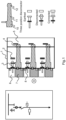
- Figs. 1-2 show examples of a switchgear for operation in a medium voltage or high voltage substation, and where the switchgear has one or more removable modules or boxes.
- the switchgear comprises a first compartment 1, at least one removable module 6, 7, a plurality of main switchgear components, and a plurality of auxiliary switchgear components.
- the plurality of main switchgear components are sub-divided into a first group of components that have a lifetime greater than a threshold level and a second group of components that have a lifetime less than or equal to the threshold level.
- the plurality of auxiliary switchgear components are sub-divided into a first group of components that have a lifetime greater than the threshold level and a second group of components that have a lifetime less than or equal to the threshold level.
- the plurality of main switchgear components in the first group of components and the plurality of auxiliary switchgear in the first group of components are housed in the first compartment.
- the plurality of main switchgear components in the second group of components and the plurality of auxiliary switchgear in the second group of components are housed in or associated with the at least one removable module. Removal of the at least one removable module from the switchgear is configured to remove the plurality of main switchgear components in the second group of components and the plurality of auxiliary switchgear in the second group of components from the switchgear. Thus, removal of the removable module allows or enables these components also to be removed from the switchgear.
- the threshold for the main switchgear components can be the same as the threshold for the auxiliary switchgear components.
- the threshold can be determined in a number of different ways, for example being an average lifetime of components in the switchgear, or a time span equal to that between major scheduled system maintenance for example. Other time thresholds can be utilized.
- the plurality of main switchgear components in the first group of components are fixedly housed in the first compartment.
- the plurality of auxiliary switchgear components in the first group of components are fixedly housed in the first compartment.
- the plurality of main switchgear components in the second group of components and the plurality of auxiliary switchgear components in the second group of components are divided into a plurality of logical groups, and wherein the components in a logical group are housed in or associated with the same removable module.
- a disconnector switch drive and auxiliaries are housed in or associated with the same removable module 6.
- the disconnector switch is a linear movement type switch or a rotational movement type switch.
- a circuit breaker control electronics and auxiliaries are located in the same removable module 7.
- the disconnector switch drive and auxiliaries are housed in or associated with a different removable module to the removable module within which the circuit breaker control electronics and auxiliaries are housed or associated.
- the removable module within which is housed or associated the circuit breaker control electronics and auxiliaries also houses or is associated with at least one part of a circuit breaker drive 10.
- interface to a circuit breaker pole 4 comprises a removable mechanical or electrical connection configured to transfer mechanical energy from the circuit breaker drive to a circuit breaker moving contact or electrical energy from the supply source to the circuit breaker drive.
- An electromagnetic drive is provided, which is fixedly coupled to the circuit breaker pole.
- the coil windings of this drive then fall into the "First group of components”.
- the energy storage capacitor and the drive control electronics then fall into the "second group of components”.
- an electrical interface is sufficient, through for example a plug in the cable from the drive controller to the motor as part of a plug and socket functionality.
- a circuit breaker single pole unit is housed in or associated with the removable module.
- the circuit breaker single pole unit utilizes a rotational circuit breaker pole.
- a vacuum interrupter located in a central axis of the pole serves as the main current switching device while rotation of the pole around the central axis is configured to act as a three position disconnector switch for connection, disconnection, and earthing.
- each phase of three phases has a same logical group.
- the logical group for each phase is housed in or associated with a different removable module.
- each phase of three phases has a same logical group, and wherein the logical group for each phase is housed in or associated with the same removable module.
- the first compartment is arc proof.
- Each removable module of the at least one removable module comprises a plug and socket connection to supply and signal collection circuits, configured to enable communication with at least one component external to the removable module.
- the at least one removable module comprises at least one plug and socket connection.
- a plug and socket connection of the at least one plug and socket connection is configured for electrical connection between a circuit breaker drive electronics and a circuit breaker drive 10.
- the switchgear comprises at least one cable connection compartment 5 within which is housed or associated at least part of at least one cable connection for at least one vacuum interrupter 11 housed in the first compartment.
- At least one bushing 12 forms part of the connection between the at least one cable connection and the at least one vacuum interrupter, and the at least one bushing comprises current and voltage sensors.
- the at least one cable connection compartment comprises at least one door or removable wall section.
- a segregating wall between the first compartment and the at least one cable connection compartment is an arc proof segregation, enabling access of a user to the cable connection compartment when at least one component in the first compartment is operational.
- a different cable connection compartment is provided for each phase of three phases for a three phase system
- the plurality of main switchgear components in the first group of components and the plurality of auxiliary switchgear in the first group of components comprises one or more of: copper bars of a primary circuit; a circuit breaker CB pole; a vacuum interrupter; post insulators; current and voltage sensors; and disconnector fixed contacts.
- the plurality of main switchgear components in the second group of components and the plurality of auxiliary switchgear in the second group of components comprises one or more of: electronic components for control and feedback collection; disconnector switch drive; circuit breaker control electronics; auxiliary switches; sensors for condition monitoring; cable terminations, and plug and socket systems.
- a primary circuit of the switchgear comprises, in other words can include, one or more of: an earthing switch, voltage indication, surge arrestor, UFES, IS-limitor, contactor, load-break switch, and fuse, and these components (and/or subcomponents of these components) when present are comprised within the second group of components of the plurality of main switchgear components or comprised within the second group of components of the plurality of auxiliary switchgear components.
- the removable module is configured to be removed from the switchgear and replaced with a different removable module of the same type.
- a new substation development is provided where the less reliable parts are separated from the more reliable parts and grouped in one or more replaceable modules for simplifying or automating the maintenance, while increasing the switchgear up-time.
- the modularization and segregation of the less reliable parts can facilitate the maintenance in both the human operated and maintained switchgear and controlgear designs as well as switchgears and controlgears with unmanned operation and maintenance designs.
- a non-robotic solution for a maintenance of internal parts of substation is provided.
- the parts needing more regular maintenance are encapsulated to removable modules outside of the substation inner room and the robotic system or manipulator is operating outside the inner room.
- the arc proof enclosure of the switchgear or controlgear main functional parts serves as the inner room borders and as a safety barrier, allowing access for maintenance tasks on the switchgear removable modules or robotic system for human personnel with the switchgear in operation.
- Fig. 1 shows a detailed example of a switchgear, where for ease of reference the following features shown are listed:
- Fig. 1 the main and auxiliary components of a switchgear or controlgear has been divided into two groups:
- the parts belonging to the first group can be designed as fixed (i.e. removable only with extra effort, tools or preparation) and not easily accessible for the maintenance systems or personnel - protected by the enclosure.
- the enclosure of the parts from the first group can be arc proof as it contains most of the primary circuit current carrying and insulating parts. But it does not have to be arc proof.
- the components belonging to the second group can be further sub grouped to logical subassemblies and encapsulated into removable modules.
- disconnector switch drive and auxiliaries can be enclosed into one module
- circuit breaker (CB) control electronics and auxiliaries can be enclosed into another module. This is shown in the detailed example of Fig. 1 .
- Each of these removable modules has a plug and socket connection to the supply and signal collection circuits allowing communication with the rest of the switchgear.
- a plug and socket connection to this component can be provided as well (for example electrical connection between the CB control electronics and the CB drive).
- the first step of any maintenance action on the parts from second group is by replacing the module with parts that require maintenance with a spare module of the same type.
- the switchgear then can stay in operation or the down-time of the affected part of the switchgear can be limited to a minimum. Meanwhile the maintenance action itself on the parts in the replaced module can be postponed to a most suitable time and does not have to be carried out urgently.
- This compartment shall be preferably segregated with arc proof segregation from the inner room of the switchgear, and is separate for each feeder circuit and is accessible for human operators or maintainers. When all covers are properly closed this compartment is preferably arc proof and enclosed against the inner room of the switchgear as well as the outer space.
- the removable modules for the disconnector switch and the circuit breaker can be designed for each phase separately. These modules can however be designed as one module per all three phases.
- a separate removable module is provided for the disconnector switch and for the circuit breaker. These modules can however be designed as one module for both the devices.
- Fig.1 the phases are arranged one above the other - the CB pole orientation being horizontal for all phases.
- the phases can be arranged in other geometries, for example poles of all phases oriented vertically or poles not being parallel and one pole oriented horizontally, with the second pole tilted 45degrees from horizontal and the last pole vertical.
- the CB poles include the current and voltage sensors.
- the sensors in a bushing can be a separate component connected to CB pole with a removable connection. Rather than having the sensors embedded into a bushing that is separate from the pole, the current and voltage sensors can be kept as stand alone devices located in the cable compartment and not integrated in the bushing.
- the disconnector switch shown in Fig.1 is a linear movement type.
- a disconnector switch with rotational movement can be used as well.
- the removable module of the circuit breaker shown in Fig.1 includes the control electronics and auxiliaries and allows simple electrical plug and socket connection to the circuit breaker drive.
- the module can also include parts of the CB drive and then the interface to the CB pole can be a removable mechanical connection transferring mechanical energy from the drive to the CB moving contact.
- the removable module can comprise the complete circuit breaker single pole unit (the pole including drive and auxiliaries). For that purpose it would be possible to use a rotational circuit breaker pole.
- the vacuum interrupter located in the central axis of the pole is then used for current interruption, while rotation of the pole around the central axis serves for connection, disconnection and earthing as three position disconnector switch.
- a removable cover of the cable termination compartment (shown on the right hand side of Fig.1 ) can be replaced with doors.
- the primary circuit of the switchgear can include other components and devices not described in Fig.1 , such as earthing switch, voltage indication, surge arrestors, UFES, IS-limiters, contactors, load-break switches, fuses.
- earthing switch voltage indication
- surge arrestors UFES
- IS-limiters contactors
- load-break switches load-break switches
- the removable module of the disconnector switch can embed the drive and auxiliaries only, or it can include the moving contact of the disconnector switch in as well. This is represented in Fig. 2 .
Landscapes
- Engineering & Computer Science (AREA)
- Power Engineering (AREA)
- Manufacturing & Machinery (AREA)
- Gas-Insulated Switchgears (AREA)
- Patch Boards (AREA)
Claims (15)
- Eine Mittel- oder Hochspannungsschaltanlage, umfassend:- ein erstes Fach (1);- mindestens ein herausnehmbares Modul (6, 7);- eine Vielzahl von Hauptschaltanlagenkomponenten und- eine Vielzahl von Hilfsschaltanlagenkomponenten;wobei die Vielzahl von Hauptschaltanlagenkomponenten einen Schutzschalterpol mit einem Vakuumschalter (11) und einen Trennschalter (3) umfasst;wobei das erste Fach lichtbogenfest ist;wobei jedes herausnehmbare Modul (6, 7) des mindestens einen herausnehmbaren Moduls eine Steckverbindung zur Versorgung und Ansteuerung von Sammelschaltkreisen umfasst, die dazu konfiguriert ist, eine Kommunikation mit mindestens einer Komponente außerhalb des herausnehmbaren Moduls zu ermöglichen;wobei die Vielzahl von Hauptschaltanlagenkomponenten in eine erste Komponentengruppe, deren Lebensdauer größer als ein Schwellenwert ist, und eine zweite Komponentengruppe, deren Lebensdauer kleiner oder gleich dem Schwellenwert ist, unterteilt ist;wobei die Vielzahl von Hilfsschaltanlagenkomponenten in eine erste Komponentengruppe, deren Lebensdauer größer als der Schwellenwert ist, und eine zweite Komponentengruppe, deren Lebensdauer kleiner oder gleich dem Schwellenwert ist, unterteilt ist;wobei die Vielzahl von Hauptschaltanlagenkomponenten in der ersten Komponentengruppe und die Vielzahl von Hilfsschaltanlagenkomponenten in der ersten Komponentengruppe fest in dem ersten Fach untergebracht (1) sind;wobei die mehreren Hauptschaltanlagenkomponenten in der zweiten Komponentengruppe und die mehreren Hilfsschaltanlagenkomponenten in der zweiten Komponentengruppe in dem mindestens einen herausnehmbaren Modul untergebracht oder mit diesem verbunden sind (6, 7);wobei die Vielzahl von Hauptschaltanlagenkomponenten in der zweiten Komponentengruppe und die Vielzahl von Hilfsschaltanlagenkomponenten in der zweiten Komponentengruppe in eine Mehrzahl logischer Gruppen unterteilt sind, wobei die Komponenten in einer logischen Gruppe in demselben herausnehmbaren Modul (6, 7) untergebracht oder diesem zugeordnet sind, wobei ein Trennschalterantrieb und Hilfsgeräte in demselben ersten herausnehmbaren Modul (6) untergebracht oder diesem zugeordnet sind und wobei eine Schutzschaltersteuerelektronik und Hilfsgeräte in demselben zweiten herausnehmbaren Modul (7) untergebracht oder diesem zugeordnet sind;wobei ein Entfernen des mindestens einen abnehmbaren Moduls von der Schaltanlage dazu eingerichtet ist, die Vielzahl von Hauptschaltanlagenkomponenten in der zweiten Komponentengruppe und die Vielzahl von Hilfsschaltanlagenkomponenten in der zweiten Komponentengruppe von der Schaltanlage zu entfernen;wobei ein elektromagnetischer Schutzschalterantrieb (10) fest mit dem Schutzschalterpol gekoppelt ist;wobei Spulenwicklungen des elektromagnetischen Schutzschalterantriebs Teil der ersten Komponentengruppe sind; undwobei ein Energiespeicherkondensator und eine Steuerelektronik des elektromagnetischen Schutzschalterantriebs Teil der zweiten Komponentengruppe sind.
- Schaltanlage nach Anspruch 1, wobei der Trennschalter ein Schalter mit linearer Bewegung oder ein Schalter mit Rotationsbewegung ist.
- Schaltanlage nach einem der Ansprüche 1 bis 2, wobei jede Phase von drei Phasen dieselbe logische Gruppe hat und wobei die logische Gruppe jeder Phase in einem anderen herausnehmbaren Modul untergebracht oder mit diesem verbunden ist.
- Schaltanlage nach einem der Ansprüche 1 bis 2, wobei jede Phase von drei Phasen dieselbe logische Gruppe hat und wobei die logische Gruppe jeder Phase in demselben herausnehmbaren Modul untergebracht oder mit diesem verbunden ist.
- Schaltanlage nach einem der Ansprüche 1 bis 4, wobei für mindestens eine bestimmte Komponente der Komponenten der Vielzahl von Hauptschaltanlagenkomponenten in der zweiten Komponentengruppe oder der Vielzahl von Hilfsschaltanlagenkomponenten in der zweiten Komponentengruppe das mindestens eine abnehmbare Modul mindestens eine Steckverbindung umfasst.
- Schaltgerät nach Anspruch 5, wobei eine Steckverbindung der mindestens einen Steckverbindung zur elektrischen Verbindung zwischen der Steuerelektronik des elektromagnetischen Schutzschalterantriebs und dem elektromagnetischen Schutzschalterantrieb (10) ausgebildet ist.
- Schaltanlage nach einem der Ansprüche 1 bis 6, wobei die Schaltanlage ein Kabelanschlussfach (5) umfasst, in dem zumindest ein Teil eines Kabelanschlusses für den im ersten Fach untergebrachten Vakuumschalter (11) untergebracht ist.
- Schaltanlage nach Anspruch 7, wobei mindestens eine Buchse (12) einen Teil der Verbindung zwischen dem mindestens einen Kabelanschluss und dem mindestens einen Vakuumschalter bildet, und wobei die mindestens eine Durchführung Strom- und Spannungssensoren umfasst.
- Schaltanlage nach einem der Ansprüche 7 bis 8, wobei das mindestens eine Kabelanschlussfach mindestens eine Tür oder einen abnehmbaren Wandabschnitt umfasst.
- Schaltanlage nach einem der Ansprüche 7 bis 9, wobei eine Trennwand zwischen dem ersten Fach und dem mindestens einen Kabelanschlussfach eine lichtbogensichere Trennung ist, die einen Zugang eines Benutzers zum Kabelanschlussfach ermöglicht, wenn mindestens eine Komponente im ersten Fach in Betrieb ist.
- Schaltanlage nach einem der Ansprüche 7 bis 10, wobei bei einem dreiphasigen System für jede Phase von drei Phasen ein anderes Kabelanschlussfach vorgesehen ist.
- Schaltanlage nach einem der Ansprüche 1 bis 11, wobei die Vielzahl von Hauptschaltanlagenkomponenten in der ersten Komponentengruppe und die Vielzahl von Hilfsschaltanlagenkomponenten in der ersten Komponentengruppe eines oder mehrere der folgenden Elemente umfassen: Kupferschienen eines Primärstromkreises; den Schutzschalter-CB-Pol; den Vakuumschalter; Pfostenisolatoren; Strom- und Spannungssensoren; und Trennerfestkontakte.
- Schaltanlage nach einem der Ansprüche 1 bis 12, wobei die Vielzahl von Hauptschaltanlagenkomponenten in der zweiten Komponentengruppe und die Vielzahl von Hilfsschaltanlagenkomponenten in der zweiten Komponentengruppe eines oder mehrere der folgenden Elemente umfassen: elektronische Komponenten für die Steuerung und die Erfassung von Rückmeldungen; Trennschalterantrieb; Hilfsschalter; Sensoren für die Zustandsüberwachung; Kabelanschlüsse und Stecksysteme.
- Schaltanlage nach einem der Ansprüche 1 bis 13, wobei ein Primärstromkreis der Schaltanlage eines oder mehrere der folgenden Elemente umfasst: einen Erdungsschalter, eine Spannungsanzeige, einen Überspannungsableiter, einen UFES, einen IS-Begrenzer, ein Schütz, einen Lasttrennschalter und eine Sicherung, und diese Komponenten, wenn vorhanden, in der zweiten von Komponentengruppe der Vielzahl von Hauptschaltanlagenkomponenten oder in der zweiten Komponentengruppe der Vielzahl von Hilfsschaltanlagenkomponenten enthalten sind.
- Schaltanlage nach einem der Ansprüche 1 bis 14, wobei jedes des mindestens einen abnehmbaren Moduls eingerichtet ist, aus der Schaltanlage entfernbar und durch ein anderes abnehmbares Modul desselben Typs ersetzbar zu sein.
Priority Applications (4)
| Application Number | Priority Date | Filing Date | Title |
|---|---|---|---|
| EP18214170.5A EP3671986B1 (de) | 2018-12-19 | 2018-12-19 | Schaltanlage |
| PCT/EP2019/084661 WO2020126743A1 (en) | 2018-12-19 | 2019-12-11 | Switchgear |
| CN201980084787.5A CN113243068B (zh) | 2018-12-19 | 2019-12-11 | 开关设备 |
| US17/344,975 US11682885B2 (en) | 2018-12-19 | 2021-06-11 | Switchgear |
Applications Claiming Priority (1)
| Application Number | Priority Date | Filing Date | Title |
|---|---|---|---|
| EP18214170.5A EP3671986B1 (de) | 2018-12-19 | 2018-12-19 | Schaltanlage |
Publications (2)
| Publication Number | Publication Date |
|---|---|
| EP3671986A1 EP3671986A1 (de) | 2020-06-24 |
| EP3671986B1 true EP3671986B1 (de) | 2025-05-14 |
Family
ID=64746239
Family Applications (1)
| Application Number | Title | Priority Date | Filing Date |
|---|---|---|---|
| EP18214170.5A Active EP3671986B1 (de) | 2018-12-19 | 2018-12-19 | Schaltanlage |
Country Status (4)
| Country | Link |
|---|---|
| US (1) | US11682885B2 (de) |
| EP (1) | EP3671986B1 (de) |
| CN (1) | CN113243068B (de) |
| WO (1) | WO2020126743A1 (de) |
Families Citing this family (5)
| Publication number | Priority date | Publication date | Assignee | Title |
|---|---|---|---|---|
| EP3671991B1 (de) * | 2018-12-19 | 2025-04-23 | ABB Schweiz AG | Dreiphasige schaltanlage |
| EP4546580A3 (de) * | 2018-12-19 | 2025-07-02 | Abb Schweiz Ag | Dreiphasige schaltanlage mit einphasiger ausrüstung in einem gehäuse |
| EP3754681B1 (de) | 2019-06-21 | 2026-01-21 | ABB Schweiz AG | Trennschalter mit drei positionen |
| EP3836322B1 (de) | 2019-12-11 | 2023-08-30 | ABB Schweiz AG | Schutzschalterpol für niederspannungs- oder mittelspannungsbetrieb |
| EP3896806B1 (de) | 2020-04-14 | 2025-12-10 | ABB Schweiz AG | Mittelspannungsschaltanlage oder -schaltgetriebe |
Citations (2)
| Publication number | Priority date | Publication date | Assignee | Title |
|---|---|---|---|---|
| CN103996990A (zh) * | 2014-05-29 | 2014-08-20 | 厦门兴厦控电气有限公司 | 一种新型充气开关柜 |
| EP2953219A1 (de) * | 2014-04-29 | 2015-12-09 | Mitsubishi Electric Corporation | Gasisolierte schaltanlage |
Family Cites Families (22)
| Publication number | Priority date | Publication date | Assignee | Title |
|---|---|---|---|---|
| DE19857170B4 (de) * | 1998-12-11 | 2009-07-09 | Abb Ag | Schaltgerät |
| AU7359500A (en) * | 1999-09-08 | 2001-04-10 | American Power Conversion, Inc. | A method and apparatus for delivering uninterrupted power |
| JP2001352621A (ja) * | 2000-06-02 | 2001-12-21 | Mitsubishi Electric Corp | ガス絶縁開閉装置 |
| JP4329923B2 (ja) * | 2002-10-31 | 2009-09-09 | 三菱電機株式会社 | ガス絶縁スイッチギヤ |
| DE10314459A1 (de) * | 2003-03-28 | 2004-10-07 | Alstom | Metallgekapselte gasisolierte Schaltanlage |
| US7186942B1 (en) * | 2006-02-23 | 2007-03-06 | Eaton Corporation | Three-position vacuum interrupter disconnect switch providing current interruption, disconnection and grounding |
| US7612988B2 (en) * | 2007-04-05 | 2009-11-03 | Satin America Corporation | Switchgear with movable user interface module |
| US7829814B2 (en) * | 2007-09-26 | 2010-11-09 | Eaton Corporation | Vacuum circuit interrupter grounding assembly |
| JP4920087B2 (ja) * | 2008-02-14 | 2012-04-18 | 三菱電機株式会社 | コントロールセンタ |
| US20130050905A1 (en) * | 2011-08-31 | 2013-02-28 | Hyundai Heavy Industries Co., Ltd. | Cubicle type gas-insulated switchgear with withdrawable circuit breaker part |
| KR101248608B1 (ko) * | 2011-08-31 | 2013-03-28 | 현대중공업 주식회사 | 차단부 인출식 큐비클형 가스절연 개폐장치 |
| KR20180054754A (ko) | 2015-09-18 | 2018-05-24 | 엑손모빌 업스트림 리서치 캄파니 | 로봇을 구비한 전기실 |
| CN105896321A (zh) * | 2016-06-29 | 2016-08-24 | 广东光达电气有限公司 | 智能滤波补偿模块结构 |
| CN207801205U (zh) * | 2018-02-02 | 2018-08-31 | 重庆三德电力设备有限公司 | 带可更换触动筒的厢式低压柜 |
| CN207459518U (zh) * | 2018-03-02 | 2018-06-05 | 北联技术股份有限公司 | 一种低电压配电柜的结构与配件 |
| WO2019175999A1 (ja) * | 2018-03-14 | 2019-09-19 | 三菱電機株式会社 | ガス絶縁開閉装置 |
| KR200492345Y1 (ko) * | 2018-09-21 | 2020-09-22 | 엘에스일렉트릭(주) | 고전압 배전반 |
| ES2887257T3 (es) * | 2018-12-19 | 2021-12-22 | Abb Schweiz Ag | Aparato de conmutación o aparato de control |
| EP4546580A3 (de) * | 2018-12-19 | 2025-07-02 | Abb Schweiz Ag | Dreiphasige schaltanlage mit einphasiger ausrüstung in einem gehäuse |
| EP3754801B1 (de) * | 2019-06-21 | 2023-03-08 | ABB Schweiz AG | Schaltanlage oder steuergeräte |
| EP3836182B1 (de) * | 2019-12-11 | 2023-03-08 | ABB Schweiz AG | Trennschalter mit drei positionen |
| EP3836322B1 (de) * | 2019-12-11 | 2023-08-30 | ABB Schweiz AG | Schutzschalterpol für niederspannungs- oder mittelspannungsbetrieb |
-
2018
- 2018-12-19 EP EP18214170.5A patent/EP3671986B1/de active Active
-
2019
- 2019-12-11 WO PCT/EP2019/084661 patent/WO2020126743A1/en not_active Ceased
- 2019-12-11 CN CN201980084787.5A patent/CN113243068B/zh active Active
-
2021
- 2021-06-11 US US17/344,975 patent/US11682885B2/en active Active
Patent Citations (2)
| Publication number | Priority date | Publication date | Assignee | Title |
|---|---|---|---|---|
| EP2953219A1 (de) * | 2014-04-29 | 2015-12-09 | Mitsubishi Electric Corporation | Gasisolierte schaltanlage |
| CN103996990A (zh) * | 2014-05-29 | 2014-08-20 | 厦门兴厦控电气有限公司 | 一种新型充气开关柜 |
Also Published As
| Publication number | Publication date |
|---|---|
| US20210305788A1 (en) | 2021-09-30 |
| WO2020126743A1 (en) | 2020-06-25 |
| EP3671986A1 (de) | 2020-06-24 |
| US11682885B2 (en) | 2023-06-20 |
| CN113243068A (zh) | 2021-08-10 |
| CN113243068B (zh) | 2024-07-26 |
Similar Documents
| Publication | Publication Date | Title |
|---|---|---|
| US11682885B2 (en) | Switchgear | |
| US6242708B1 (en) | Isolator switch | |
| EP1245065B1 (de) | Integrales lastanschlussmodul | |
| WO2001050561A1 (en) | Modular, miniaturized switchgear | |
| CN101106034B (zh) | 提供电流中断、隔离和接地的三位置真空断续器隔离开关 | |
| JP2008104338A (ja) | 真空絶縁スイッチギヤ | |
| EP3671989B1 (de) | Dreiphasen-schaltanlage mit einphasiger ausrüstung in einem gehäuse | |
| US11139642B2 (en) | Switchgear or control gear | |
| US8379373B2 (en) | Vacuum insulated switchgear including a bus recovery member | |
| US11005240B2 (en) | Three phase switchgear or control gear | |
| JP5026537B2 (ja) | スイッチギヤ | |
| EP3671991B1 (de) | Dreiphasige schaltanlage | |
| EP3754801B1 (de) | Schaltanlage oder steuergeräte | |
| KR19990036805A (ko) | 스위치 기어 | |
| Bode | Switchgear for 2000 and beyond | |
| CZ11978U1 (cs) | Dvousystémová kobková rozvodna | |
| HK1159866A (zh) | 开关装置 |
Legal Events
| Date | Code | Title | Description |
|---|---|---|---|
| PUAI | Public reference made under article 153(3) epc to a published international application that has entered the european phase |
Free format text: ORIGINAL CODE: 0009012 |
|
| STAA | Information on the status of an ep patent application or granted ep patent |
Free format text: STATUS: THE APPLICATION HAS BEEN PUBLISHED |
|
| AK | Designated contracting states |
Kind code of ref document: A1 Designated state(s): AL AT BE BG CH CY CZ DE DK EE ES FI FR GB GR HR HU IE IS IT LI LT LU LV MC MK MT NL NO PL PT RO RS SE SI SK SM TR |
|
| AX | Request for extension of the european patent |
Extension state: BA ME |
|
| STAA | Information on the status of an ep patent application or granted ep patent |
Free format text: STATUS: REQUEST FOR EXAMINATION WAS MADE |
|
| 17P | Request for examination filed |
Effective date: 20201201 |
|
| RBV | Designated contracting states (corrected) |
Designated state(s): AL AT BE BG CH CY CZ DE DK EE ES FI FR GB GR HR HU IE IS IT LI LT LU LV MC MK MT NL NO PL PT RO RS SE SI SK SM TR |
|
| STAA | Information on the status of an ep patent application or granted ep patent |
Free format text: STATUS: EXAMINATION IS IN PROGRESS |
|
| 17Q | First examination report despatched |
Effective date: 20210804 |
|
| GRAP | Despatch of communication of intention to grant a patent |
Free format text: ORIGINAL CODE: EPIDOSNIGR1 |
|
| STAA | Information on the status of an ep patent application or granted ep patent |
Free format text: STATUS: GRANT OF PATENT IS INTENDED |
|
| INTG | Intention to grant announced |
Effective date: 20241223 |
|
| GRAS | Grant fee paid |
Free format text: ORIGINAL CODE: EPIDOSNIGR3 |
|
| GRAA | (expected) grant |
Free format text: ORIGINAL CODE: 0009210 |
|
| STAA | Information on the status of an ep patent application or granted ep patent |
Free format text: STATUS: THE PATENT HAS BEEN GRANTED |
|
| RAP3 | Party data changed (applicant data changed or rights of an application transferred) |
Owner name: ABB SCHWEIZ AG |
|
| AK | Designated contracting states |
Kind code of ref document: B1 Designated state(s): AL AT BE BG CH CY CZ DE DK EE ES FI FR GB GR HR HU IE IS IT LI LT LU LV MC MK MT NL NO PL PT RO RS SE SI SK SM TR |
|
| REG | Reference to a national code |
Ref country code: GB Ref legal event code: FG4D |
|
| REG | Reference to a national code |
Ref country code: CH Ref legal event code: EP |
|
| REG | Reference to a national code |
Ref country code: DE Ref legal event code: R096 Ref document number: 602018081892 Country of ref document: DE |
|
| REG | Reference to a national code |
Ref country code: IE Ref legal event code: FG4D |
|
| REG | Reference to a national code |
Ref country code: NL Ref legal event code: MP Effective date: 20250514 |
|
| PG25 | Lapsed in a contracting state [announced via postgrant information from national office to epo] |
Ref country code: FI Free format text: LAPSE BECAUSE OF FAILURE TO SUBMIT A TRANSLATION OF THE DESCRIPTION OR TO PAY THE FEE WITHIN THE PRESCRIBED TIME-LIMIT Effective date: 20250514 Ref country code: ES Free format text: LAPSE BECAUSE OF FAILURE TO SUBMIT A TRANSLATION OF THE DESCRIPTION OR TO PAY THE FEE WITHIN THE PRESCRIBED TIME-LIMIT Effective date: 20250514 Ref country code: PT Free format text: LAPSE BECAUSE OF FAILURE TO SUBMIT A TRANSLATION OF THE DESCRIPTION OR TO PAY THE FEE WITHIN THE PRESCRIBED TIME-LIMIT Effective date: 20250915 |
|
| REG | Reference to a national code |
Ref country code: LT Ref legal event code: MG9D |
|
| PG25 | Lapsed in a contracting state [announced via postgrant information from national office to epo] |
Ref country code: NO Free format text: LAPSE BECAUSE OF FAILURE TO SUBMIT A TRANSLATION OF THE DESCRIPTION OR TO PAY THE FEE WITHIN THE PRESCRIBED TIME-LIMIT Effective date: 20250814 Ref country code: GR Free format text: LAPSE BECAUSE OF FAILURE TO SUBMIT A TRANSLATION OF THE DESCRIPTION OR TO PAY THE FEE WITHIN THE PRESCRIBED TIME-LIMIT Effective date: 20250815 |
|
| PG25 | Lapsed in a contracting state [announced via postgrant information from national office to epo] |
Ref country code: NL Free format text: LAPSE BECAUSE OF FAILURE TO SUBMIT A TRANSLATION OF THE DESCRIPTION OR TO PAY THE FEE WITHIN THE PRESCRIBED TIME-LIMIT Effective date: 20250514 Ref country code: PL Free format text: LAPSE BECAUSE OF FAILURE TO SUBMIT A TRANSLATION OF THE DESCRIPTION OR TO PAY THE FEE WITHIN THE PRESCRIBED TIME-LIMIT Effective date: 20250514 |
|
| REG | Reference to a national code |
Ref country code: AT Ref legal event code: MK05 Ref document number: 1795652 Country of ref document: AT Kind code of ref document: T Effective date: 20250514 |
|
| PG25 | Lapsed in a contracting state [announced via postgrant information from national office to epo] |
Ref country code: BG Free format text: LAPSE BECAUSE OF FAILURE TO SUBMIT A TRANSLATION OF THE DESCRIPTION OR TO PAY THE FEE WITHIN THE PRESCRIBED TIME-LIMIT Effective date: 20250514 |
|
| PG25 | Lapsed in a contracting state [announced via postgrant information from national office to epo] |
Ref country code: HR Free format text: LAPSE BECAUSE OF FAILURE TO SUBMIT A TRANSLATION OF THE DESCRIPTION OR TO PAY THE FEE WITHIN THE PRESCRIBED TIME-LIMIT Effective date: 20250514 |
|
| PG25 | Lapsed in a contracting state [announced via postgrant information from national office to epo] |
Ref country code: AT Free format text: LAPSE BECAUSE OF FAILURE TO SUBMIT A TRANSLATION OF THE DESCRIPTION OR TO PAY THE FEE WITHIN THE PRESCRIBED TIME-LIMIT Effective date: 20250514 |
|
| PG25 | Lapsed in a contracting state [announced via postgrant information from national office to epo] |
Ref country code: RS Free format text: LAPSE BECAUSE OF FAILURE TO SUBMIT A TRANSLATION OF THE DESCRIPTION OR TO PAY THE FEE WITHIN THE PRESCRIBED TIME-LIMIT Effective date: 20250814 |
|
| PG25 | Lapsed in a contracting state [announced via postgrant information from national office to epo] |
Ref country code: IS Free format text: LAPSE BECAUSE OF FAILURE TO SUBMIT A TRANSLATION OF THE DESCRIPTION OR TO PAY THE FEE WITHIN THE PRESCRIBED TIME-LIMIT Effective date: 20250914 |
|
| PG25 | Lapsed in a contracting state [announced via postgrant information from national office to epo] |
Ref country code: LV Free format text: LAPSE BECAUSE OF FAILURE TO SUBMIT A TRANSLATION OF THE DESCRIPTION OR TO PAY THE FEE WITHIN THE PRESCRIBED TIME-LIMIT Effective date: 20250514 |
|
| PGFP | Annual fee paid to national office [announced via postgrant information from national office to epo] |
Ref country code: DE Payment date: 20251211 Year of fee payment: 8 |
|
| PG25 | Lapsed in a contracting state [announced via postgrant information from national office to epo] |
Ref country code: SM Free format text: LAPSE BECAUSE OF FAILURE TO SUBMIT A TRANSLATION OF THE DESCRIPTION OR TO PAY THE FEE WITHIN THE PRESCRIBED TIME-LIMIT Effective date: 20250514 Ref country code: DK Free format text: LAPSE BECAUSE OF FAILURE TO SUBMIT A TRANSLATION OF THE DESCRIPTION OR TO PAY THE FEE WITHIN THE PRESCRIBED TIME-LIMIT Effective date: 20250514 |
|
| PGFP | Annual fee paid to national office [announced via postgrant information from national office to epo] |
Ref country code: IT Payment date: 20251223 Year of fee payment: 8 |
|
| PGFP | Annual fee paid to national office [announced via postgrant information from national office to epo] |
Ref country code: FR Payment date: 20251229 Year of fee payment: 8 |
|
| PG25 | Lapsed in a contracting state [announced via postgrant information from national office to epo] |
Ref country code: CZ Free format text: LAPSE BECAUSE OF FAILURE TO SUBMIT A TRANSLATION OF THE DESCRIPTION OR TO PAY THE FEE WITHIN THE PRESCRIBED TIME-LIMIT Effective date: 20250514 |
|
| PG25 | Lapsed in a contracting state [announced via postgrant information from national office to epo] |
Ref country code: EE Free format text: LAPSE BECAUSE OF FAILURE TO SUBMIT A TRANSLATION OF THE DESCRIPTION OR TO PAY THE FEE WITHIN THE PRESCRIBED TIME-LIMIT Effective date: 20250514 |
|
| PG25 | Lapsed in a contracting state [announced via postgrant information from national office to epo] |
Ref country code: RO Free format text: LAPSE BECAUSE OF FAILURE TO SUBMIT A TRANSLATION OF THE DESCRIPTION OR TO PAY THE FEE WITHIN THE PRESCRIBED TIME-LIMIT Effective date: 20250514 Ref country code: SK Free format text: LAPSE BECAUSE OF FAILURE TO SUBMIT A TRANSLATION OF THE DESCRIPTION OR TO PAY THE FEE WITHIN THE PRESCRIBED TIME-LIMIT Effective date: 20250514 |
|
| REG | Reference to a national code |
Ref country code: DE Ref legal event code: R097 Ref document number: 602018081892 Country of ref document: DE |
|
| PLBE | No opposition filed within time limit |
Free format text: ORIGINAL CODE: 0009261 |
|
| STAA | Information on the status of an ep patent application or granted ep patent |
Free format text: STATUS: NO OPPOSITION FILED WITHIN TIME LIMIT |
|
| REG | Reference to a national code |
Ref country code: CH Ref legal event code: L10 Free format text: ST27 STATUS EVENT CODE: U-0-0-L10-L00 (AS PROVIDED BY THE NATIONAL OFFICE) Effective date: 20260325 |
|
| 26N | No opposition filed |
Effective date: 20260217 |