EP3671902B1 - Batteriemodul mit busschienenanordnung - Google Patents
Batteriemodul mit busschienenanordnung Download PDFInfo
- Publication number
- EP3671902B1 EP3671902B1 EP18884722.2A EP18884722A EP3671902B1 EP 3671902 B1 EP3671902 B1 EP 3671902B1 EP 18884722 A EP18884722 A EP 18884722A EP 3671902 B1 EP3671902 B1 EP 3671902B1
- Authority
- EP
- European Patent Office
- Prior art keywords
- bus bar
- electrode lead
- connection bus
- insert groove
- connection
- Prior art date
- Legal status (The legal status is an assumption and is not a legal conclusion. Google has not performed a legal analysis and makes no representation as to the accuracy of the status listed.)
- Active
Links
Images


Classifications
-
- H—ELECTRICITY
- H01—ELECTRIC ELEMENTS
- H01M—PROCESSES OR MEANS, e.g. BATTERIES, FOR THE DIRECT CONVERSION OF CHEMICAL ENERGY INTO ELECTRICAL ENERGY
- H01M50/00—Constructional details or processes of manufacture of the non-active parts of electrochemical cells other than fuel cells, e.g. hybrid cells
- H01M50/50—Current conducting connections for cells or batteries
- H01M50/502—Interconnectors for connecting terminals of adjacent batteries; Interconnectors for connecting cells outside a battery casing
-
- H—ELECTRICITY
- H01—ELECTRIC ELEMENTS
- H01M—PROCESSES OR MEANS, e.g. BATTERIES, FOR THE DIRECT CONVERSION OF CHEMICAL ENERGY INTO ELECTRICAL ENERGY
- H01M50/00—Constructional details or processes of manufacture of the non-active parts of electrochemical cells other than fuel cells, e.g. hybrid cells
- H01M50/20—Mountings; Secondary casings or frames; Racks, modules or packs; Suspension devices; Shock absorbers; Transport or carrying devices; Holders
- H01M50/204—Racks, modules or packs for multiple batteries or multiple cells
- H01M50/207—Racks, modules or packs for multiple batteries or multiple cells characterised by their shape
- H01M50/211—Racks, modules or packs for multiple batteries or multiple cells characterised by their shape adapted for pouch cells
-
- H—ELECTRICITY
- H01—ELECTRIC ELEMENTS
- H01M—PROCESSES OR MEANS, e.g. BATTERIES, FOR THE DIRECT CONVERSION OF CHEMICAL ENERGY INTO ELECTRICAL ENERGY
- H01M50/00—Constructional details or processes of manufacture of the non-active parts of electrochemical cells other than fuel cells, e.g. hybrid cells
- H01M50/50—Current conducting connections for cells or batteries
- H01M50/502—Interconnectors for connecting terminals of adjacent batteries; Interconnectors for connecting cells outside a battery casing
- H01M50/503—Interconnectors for connecting terminals of adjacent batteries; Interconnectors for connecting cells outside a battery casing characterised by the shape of the interconnectors
-
- H—ELECTRICITY
- H01—ELECTRIC ELEMENTS
- H01M—PROCESSES OR MEANS, e.g. BATTERIES, FOR THE DIRECT CONVERSION OF CHEMICAL ENERGY INTO ELECTRICAL ENERGY
- H01M50/00—Constructional details or processes of manufacture of the non-active parts of electrochemical cells other than fuel cells, e.g. hybrid cells
- H01M50/50—Current conducting connections for cells or batteries
- H01M50/502—Interconnectors for connecting terminals of adjacent batteries; Interconnectors for connecting cells outside a battery casing
- H01M50/514—Methods for interconnecting adjacent batteries or cells
- H01M50/517—Methods for interconnecting adjacent batteries or cells by fixing means, e.g. screws, rivets or bolts
-
- H—ELECTRICITY
- H01—ELECTRIC ELEMENTS
- H01M—PROCESSES OR MEANS, e.g. BATTERIES, FOR THE DIRECT CONVERSION OF CHEMICAL ENERGY INTO ELECTRICAL ENERGY
- H01M50/00—Constructional details or processes of manufacture of the non-active parts of electrochemical cells other than fuel cells, e.g. hybrid cells
- H01M50/50—Current conducting connections for cells or batteries
- H01M50/531—Electrode connections inside a battery casing
-
- H—ELECTRICITY
- H01—ELECTRIC ELEMENTS
- H01M—PROCESSES OR MEANS, e.g. BATTERIES, FOR THE DIRECT CONVERSION OF CHEMICAL ENERGY INTO ELECTRICAL ENERGY
- H01M2220/00—Batteries for particular applications
- H01M2220/20—Batteries in motive systems, e.g. vehicle, ship, plane
-
- Y—GENERAL TAGGING OF NEW TECHNOLOGICAL DEVELOPMENTS; GENERAL TAGGING OF CROSS-SECTIONAL TECHNOLOGIES SPANNING OVER SEVERAL SECTIONS OF THE IPC; TECHNICAL SUBJECTS COVERED BY FORMER USPC CROSS-REFERENCE ART COLLECTIONS [XRACs] AND DIGESTS
- Y02—TECHNOLOGIES OR APPLICATIONS FOR MITIGATION OR ADAPTATION AGAINST CLIMATE CHANGE
- Y02E—REDUCTION OF GREENHOUSE GAS [GHG] EMISSIONS, RELATED TO ENERGY GENERATION, TRANSMISSION OR DISTRIBUTION
- Y02E60/00—Enabling technologies; Technologies with a potential or indirect contribution to GHG emissions mitigation
- Y02E60/10—Energy storage using batteries
Definitions
- the present disclosure relates to a battery module including a bus bar assembly, and more particularly, to a battery module allowing improved manufacturing due to easy electric connection between the bus bar assembly and secondary batteries.
- Secondary batteries currently commercialized include nickel cadmium batteries, nickel hydrogen batteries, nickel zinc batteries, lithium secondary batteries and so on.
- the lithium secondary batteries are more highlighted in comparison to nickel-based secondary batteries due to advantages such as free charging and discharging, caused by substantially no memory effect, very low self-discharge rate, and high energy density.
- the lithium secondary battery mainly uses lithium-based oxides and carbonaceous materials as a positive electrode active material and a negative electrode active material, respectively.
- the lithium secondary battery includes an electrode assembly in which a positive electrode plate coated with the positive electrode active material and a negative electrode plate coated with the negative electrode active material are disposed with a separator being interposed therebetween, and an exterior, namely a pouch exterior, sealably containing the electrode assembly together with an electrolyte.
- the lithium secondary battery may be classified into a can-type secondary battery in which the electrode assembly is included in a metal can and a pouch-type secondary battery in which the electrode assembly is included in a pouch made of aluminum laminate sheets, depending on the shape of the exterior.
- secondary batteries have been widely used not only in small-sized devices such as portable electronic devices but also in medium-sized or large-sized devices such as vehicles and power storage devices.
- the secondary batteries are used in the middle-sized or large-sized devices, a large number of secondary batteries are electrically connected to increase capacity and power.
- pouch-type secondary batteries are widely used for the middle-sized or large-sized devices since they may be easily stacked.
- electrode leads are connected to each other, and the connection portions may be welded to maintain the connected state.
- the battery module may have parallel and/or series electrical connections between the secondary batteries.
- one end of the electrode lead may be fixed in contact to the bus bar by welding or the like for electrical connection between to each secondary battery.
- the electrical connection between the secondary batteries is frequently configured by bonding the electrode leads to the bus bar. That is, in order to electrically connect a plurality of secondary batteries in parallel, electrode leads of the same polarity are bonded to each other. Also, in order to electrically connect a plurality of secondary batteries in series, electrode leads of different polarities are bonded to each other.
- the electrode lead is made of a weak material, a worker may easily damage the electrode lead while detaching a coupled electrode lead or bonding the detached electrode lead again when the bus bar and the electrode lead are bonded poorly or erroneously. Thus, it is impossible to perform the rework.
- the electrode lead and the bus bar are not easily adhered closely to each other since the bent electrode causes a spring-back phenomenon. Accordingly, since laser welding should be performed in a state where a plurality of electrode leads are closely adhered to each other, the weldability may be easily deteriorated.
- US 2012/301747 A1 refers to a battery pack, which includes: a battery cell including a cell tab; a housing configured to accommodate the battery cell; a middle cover configured to close the housing in a state where the cell tab extends outward through the middle cover; a bus bar electrically connected to the cell tab extending outward through the middle cover; a sensing circuit board disposed on the bus bar and electrically connected to the bus bar; an isolation plate coupled to the middle cover to cover the bus bar and the sensing circuit board; and a battery management system disposed on the isolation plate and electrically connected to the sensing circuit board.
- US 2012/328908 A1 refers to a battery pack, which comprises a battery module disposed inside a case, the battery module including a plurality of battery units, each including first and second lead tabs which protrude outside of each battery unit and which have bent portions.
- An insulation plate includes a plurality of ribs, wherein the bent portions of the lead tabs extend over the ribs, and a plurality of bus bars are disposed over the lead tabs and electrically connect the battery units serially with each other, the bus bars being fixed to the ribs.
- EP 3 046 164 A1 relates to an electricity storage module, which includes a layered object obtained by layering power storage elements each having positive and negative foil shaped lead terminals that project in an outward direction from an end portion, and connection members that connect the lead terminals of adjacent power storage elements to each other.
- An insulating holding member is arranged between the layered object and the connection members.
- Connection member holding portions that hold the connection members on the surface on the side opposite to the surface that opposes the layered object are provided on the insulating holding member, and slits are provided on the insulating holding member so as to extend along edge portions of the connection members held by the connection member holding portions.
- the lead terminals are connected to the connection members by being inserted through the slits and folded over onto the connection members.
- JP 2015 056 342 A refers to a power storage module.
- the power storage module comprises: a laminate formed by laminating a plurality of power storage elements having foil lead terminals of positive and negative electrodes projecting from edges toward an outside direction; and a connection member connecting lead terminals of adjacent power storage elements.
- an insulation keeping member is arranged between the laminate and the connection member, a connection member holding part for holding the connection member to a surface thereof opposite to a surface facing the laminate is provided on the insulation keeping member, and a slit is provided along an edge of the connection member held on the connection member holding part on the insulation keeping member, and lead terminals pass through the slit, are folded and superposed on, and are connected to the connection member.
- the present disclosure is designed to solve the problems of the related art, and therefore the present disclosure is directed to providing a battery module, which may allow improved manufacturing due to easy electric connection between a bus bar assembly and secondary batteries.
- the battery module comprises:
- a width of the insert groove in the upper and lower direction may be equal to or greater than a length of the electrode lead inserted into the insert groove in the upper and lower direction.
- the insert groove may be formed to extend from one side end to the other side end of a front surface of the connection bus bar.
- a perforation hole may be formed at the electrode lead so that the fastening bolt is inserted therein.
- a bent end portion of an electrode lead inserted from a left side to a right side of the connection bus bar and a bent end portion of an electrode lead inserted from a right side to a left side of the connection bus bar may be stacked on each other in the insert groove.
- the insert groove may be formed in plural at the connection bus bar.
- a part of the plurality of insert grooves may be formed to extend from a left end to a center of the front surface of the connection bus bar, and the other of the plurality of insert grooves may be formed to extend from a right end to the center of the front surface of the connection bus bar.
- an end portion of the at least one electrode lead inserted from the left side to the right side of the front surface of the connection bus bar may be inserted into the insert groove formed to extend from the left end to the center of the front surface of the connection bus bar.
- an end portion of the at least one electrode lead inserted from the right side to the left side of the front surface of the connection bus bar may be inserted into the insert groove formed to extend from the right end to the center of the front surface of the connection bus bar.
- the electrode lead may include a positive electrode lead and a negative electrode lead. Also, a depth of the insert groove into which the positive electrode lead is inserted and a depth of the insert groove into which the negative electrode lead is inserted may be different.
- the battery module may effectively compress the electrode lead by using the coupling bus bar and allow reliable electrical connection without a joining process such as laser welding between the connection bus bar and the electrode lead.
- connection bus bar and the coupling bus bar may be securely fixed to the bus bar frame using a fastening member
- the battery module may have enhanced product durability, and further, the fastening member may compress the coupling bus bar to securely fix the electrode lead to the insert groove.
- the coupling bus bar may press the electrode lead inserted into the insert groove with an appropriate compression force to achieve a reliable electrical connection between the electrode lead and the connection bus bar.
- the present disclosure if the battery module of the present disclosure is used, even during a work for separating the bus bar assembly from the cell stack due to erroneously bonding or erroneously assembling, the electrode lead in contact with the bus bar may be easily detached, and further, it is easy to reconnect the separated connection bus bar to the electrode lead.
- the present disclosure has an advantage that the reassembling is possible without a large damage of the electrode lead.
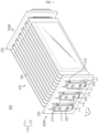
- FIG. 1 is a perspective view schematically showing a battery module according to an embodiment of the present disclosure.
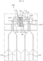
- FIG. 2 is a front schematically showing the battery module according to an embodiment of the present disclosure.
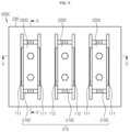
- FIG. 3 is a rear view schematically showing the battery module according to an embodiment of the present disclosure.
- FIG. 4 is a plane view schematically showing a secondary battery, which is a component of the battery module according to an embodiment of the present disclosure.
- a battery module 300 includes a cell stack 310 and bus bar assemblies 200A, 200B.
- the cell stack 310 includes a plurality of secondary batteries 100, which respectively have electrode leads 110.
- the secondary battery 100 is a pouch-type secondary battery 100.
- the pouch-type secondary battery 100 may include an electrode assembly, an electrolyte and a pouch 120.
- the pouch 120 may be composed of two pouches, namely a left pouch and a right pouch, each having a concave accommodation portion 115.
- the electrolyte assembly and the electrolyte may be accommodated in the accommodation portion 115.
- each pouch includes an outer insulating layer, a metal layer and an inner adhesive layer, and the inner adhesive layer is fused to each other at an edge of the pouch 120 to form a sealing portion.
- terrace portions S may be formed at both end portions of the pouch 120 at which a positive electrode lead 111 and a negative electrode lead 112 are formed, respectively.
- the electrode assembly is an assembly of an electrode and a separator, and at least one positive electrode plate and at least one negative electrode plate may be disposed with a separator interposed therebetween.
- a positive electrode tab is provided at the positive electrode plate of the electrode assembly, and at least one positive electrode tab may be connected to the positive electrode lead 111.
- the positive electrode lead 111 has one end connected to the positive electrode tab and the other end exposed out of the pouch 120.
- the exposed portion may serve as an electrode terminal of the secondary battery 100, for example a positive electrode terminal of the secondary battery 100.
- a negative electrode plate of the electrode assembly includes a negative electrode tab, and at least one negative electrode tab may be connected to a negative electrode lead 112.
- the negative electrode lead 112 has one end connected to the negative electrode tab and the other end exposed out of the pouch, and the exposed portion may serve as an electrode terminal of the secondary battery 100, for example a negative electrode terminal of the secondary battery 100.
- the positive electrode lead 111 and negative electrode lead 112 may be formed at both ends opposite to each other, based on the center of the secondary battery 100. Namely, the positive electrode lead 111 may be provided at one end portion, based on the center of the secondary battery 100. In addition, the negative electrode lead 112 may be provided at the other end portion, based on the center of the secondary battery 100. For example, as shown in FIGS. 1 and 2 , each secondary battery 100 may be configured such that the positive electrode lead 111 and the negative electrode lead 112 protrude forward and backward.
- the positive electrode lead 111 and the negative electrode lead 112 may be configured in a plate form.
- the positive electrode lead 111 and the negative electrode lead 112 may protrude in a horizontal direction in a state of standing so that their broad surfaces are oriented to left and right sides.
- the secondary battery 100 may be provided in plural in the battery module 300, and the plurality of secondary batteries 100 may be arranged to be stacked in at least one direction.
- a plurality of pouch-type secondary batteries 100 may be stacked on each other in parallel in the right and left direction.
- each pouch-type secondary battery 100 may be disposed to stand approximately perpendicular to the ground so that two broad surfaces positioned are respectively located at left and right and the sealing portions are located at upper, lower, front and rear portions, when viewed in the direction F (shown in FIG. 1 ).
- each secondary battery 100 may be configured in a vertically standing form.
- the upper, lower, front, rear, right and left directions are set based on the direction F, unless otherwise specified.
- the bus bar assembly 200A includes a connection bus bar 210 and a coupling bus bar 220A.
- connection bus bar 210 is configured to contact two or more of the electrode leads 110 of the cell stack 310. That is, the connection bus bar 210 may be configured to electrically connect two or more secondary batteries 100 with each other in parallel and/or in series.
- connection bus bar 210 may include an electrically conductive material. More specifically, the electrically conductive material may be a metal with high conductivity, for example copper, aluminum, nickel or gold.
- connection bus bars 210 are configured to electrically connect twelve secondary batteries 100 in parallel and in series.
- three connection bus bars 210A of FIG. 2 may be in contact with four positive electrode leads 111 or four negative electrode leads 112.
- two connection bus bars 210B of FIG. 3 are in contact with two positive electrode leads 111 and two negative electrode leads 112.
- two connection bus bars 210B2 of FIG. 2 are contacted and connected to two negative electrode leads 112, respectively.
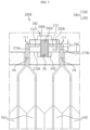
- FIG. 5 is a partial cross-sectioned view schematically showing the battery module, taken along the line A-A' of FIG. 2 .
- connection bus bar 210A includes an insert groove 212 formed so that the at least one electrode lead 110 is inserted therein.
- a portion of the insert groove 212 is recessed at the front surface of the connection bus bar 210A from a front end to a rear end thereof.
- the recessed depth D1 of the insert groove 212 is equal to the entire thickness T1 of the at least one electrode lead 110 in the inserting direction, inserted into the insert groove 212.
- the outer surface of the at least one electrode lead 110 inserted into the insert groove 212 is located on the same line as the surface of the front end of the connection bus bar 210A where the insert groove 212 is not formed, or the outer surface of the at least one electrode lead 110 may be positioned to protrude forwards further to the front end of the connection bus bar 210A.
- the width of the insert groove 212 in the upper and lower direction may be greater than the length of the electrode lead 110 in the upper and lower direction, inserted into the insert groove 212.
- the coupling bus bar 220A is coupled to the connection bus bar 210A and is located at the front end of the connection bus bar 210A. That is, the rear surface of the coupling bus bar 220A is formed to press the front surface of the electrode lead 110 in contact with the insert groove 212 of the connection bus bar 210A.
- the coupling bus bar 220A may include an electrically conductive material. More specifically, the electrically conductive material may be a metal with high conductivity, for example copper, aluminum, nickel or gold.
- the electrode lead 110 since the front surface of the at least one electrode lead 110 inserted into the insert groove 212 is located on the same line as the front surface of the connection bus bar 210A or located to protrude further therefrom, the electrode lead 110 may be effectively compressed to the coupling bus bar 220A. Accordingly, a highly reliable electrical connection may be achieved without a bonding process such as laser welding between the connection bus bar 210A and the electrode lead 110. Also, the electrode lead 110 may be firmly fixed in the insert groove 212 by compression of the coupling bus bar 220A.
- connection bus bar 210A and the coupling bus bar 220A have a bar shape extending in the upper and lower direction, when viewed macroscopically.
- the connection bus bar 210A and the coupling bus bar 220A include a front surface, a rear surface and side surfaces.
- the insert groove 212 is formed at the front surface of the connection bus bar 210A.
- the bus bar assembly 200A further includes a bus bar frame 230.
- connection bus bar 210A is loaded on the front surface of the bus bar frame 230 to fix the connection bus bar 210A.
- the bus bar frame 230 may position the connection bus bar 210A so that the electrode lead 110 of the cell stack 310 is in contact with the connection bus bar 210A at a suitable position.
- the bus bar frame 230 may include an electrically insulating material.
- the electrically insulating material may be plastic.
- the bus bar frame 230 is positioned between the front portion of the body of the secondary battery 100 and the rear portion of the connection bus bar 210A. That is, the bus bar frame 230 is configured to have a perforation hole H4 through which the electrode lead 110 of the cell stack 310 passes, or so that the electrode lead 110 passes by the side portion of the bus bar frame 230 and protrudes forwards.
- the battery module 300 includes two bus bar frames 230 located at front and rear portions, respectively.
- the bus bar frame 230 located at the front portion is located between the front portion of the body of the secondary battery 100 of the cell stack 310 and the rear portion of the connection bus bar 210A, and the connection bus bar 210A is mounted on the front surface of the bus bar frame 230.
- the bus bar frame 230 is made of an insulating material to prevent a short circuit from occurring between the connection bus bar 210A and the secondary battery 100. Also, since the connection bus bar 210A is fixed to the front surface of the bus bar frame 230, electrical connection between the connection bus bar 210A and the electrode lead 110 may be easily achieved.
- the bus bar assembly 200A further includes a fastening member 240 configured to couple the connection bus bar 210A and the coupling bus bar 220A to each other.
- the fastening member 240 includes a fastening bolt 242 inserted through the connection bus bar 210A and the coupling bus bar 220A.
- the fastening bolt 242 may include a head 242b and a cylindrical rod 242a.
- a thread may be formed on the cylindrical rod 242a.
- the cylindrical rod 242a is inserted and fixed in the bus bar frame 230.
- a fastening groove H5 may be formed at the bus bar frame 230 so that a portion of the cylindrical rod 242a may be inserted and fixed therein.
- the fastening member 240 may further include a nut 243 configured so that the cylindrical rod 242a of the fastening bolt 242 is inserted and fixed therein. Further, the nut 243 may be inserted and fixed in the bus bar frame 230. That is, the fastening bolt 242 is configured such that the cylindrical rod 242a passes through the connection bus bar 210A and the coupling bus bar 220A, and an end portion of the cylindrical rod 242a is inserted and fixed in the nut 243 inserted in the bus bar frame 230.
- the bus bar assembly 200A may stably fix the connection bus bar 210A and the coupling bus bar 220A to the bus bar frame 230 by using the fastening member 240, it is possible to increase the product durability.
- connection bus bar 210A and the coupling bus bar 220A may be controlled by adjusting the distance between the head 242b of the fastening bolt 242 and the bus bar frame 230, the coupling bus bar 220A may press the electrode lead 110 inserted into the insert groove 212 with an appropriate compression force so that the electrode lead 110 and the connection bus bar 210A are electrically connected reliably.
- the insert groove 212 may be formed in plural at the connection bus bar 210. Specifically, some of the plurality of insert grooves 212 may be shaped to extend from the left end to the center of the front surface of the connection bus bar 210. In addition, the other of the plurality of insert grooves 212 may extend from the right end to the center of the front surface of the connection bus bar 210.
- the end portion of the at least one electrode lead 110 inserted from the left side to the right side of the front surface of the connection bus bar 210 may be inserted into the insert groove 212 formed to extend from the left end 210a to the center of the front surface of the connection bus bar 210.
- the end portion of the at least one electrode lead 110 inserted from the right side to the left side of the front surface of the connection bus bar 210 may be inserted into the insert groove 212 formed to extend from the right end 210B to the center of the front surface of the connection bus bar 210.
- two insert grooves 212 may be formed at the front surface of the connection bus bar 210.
- One insert groove 212 may be shaped to extend from the left end 210a to the center of the front surface of the connection bus bar 210.
- the other insert groove 212 may be shaped to extend from the right end 210b to the center of the front surface of the connection bus bar 210.
- two stacked positive electrode leads 111 inserted from the left side to the right side of the front surface of the connection bus bar 210 may be placed in the insert groove 212 extending from the left end 210a to the center.
- end portions of the two stacked positive electrode leads 111 inserted from the right side to the left side of the front surface of the connection bus bar 210 may be placed in the insert groove 212 extending from the right end 210b to the center.
- a side surface of the electrode lead 110 having a relatively larger surface than the other surfaces is placed in the insert groove 212 of the connection bus bar 210 and compresses the electrode lead 110 to the rear surface of the coupling bus bar 220A, thereby allowing highly reliable electric connection without a bonding process such as laser welding between the bus bar and the electrode lead 110 and also stably fixing the electrode lead 110 to the insert groove 212.
- the electrode lead 110 contacting the bus bar may be easily detached during the work of separating the bus bar assembly 200A from the cell stack 310 due to erroneously bonding or erroneous assembling. Further, in the present disclosure, the separated connection bus bar 210 may be easily connected to the electrode lead 110 again. Moreover, even though it is impossible in the prior art to rework the bus bar assembly 200A due to damage of the electrode lead 110, the present disclosure allows the rework without seriously damaging the electrode lead 110.
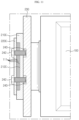
- FIG. 6 is a partial cross-sectioned view schematically showing components of a bus bar assembly employed at the battery module, taken along the line B-B' of FIG. 3 .
- a plurality of positive electrode leads 111 and a plurality of negative electrode leads 112 may be connected to one connection bus bar 210B. Also, the thicknesses T1 of the plurality of positive electrode leads 111 and the plurality of negative electrode leads 112 in the direction of being inserted into the insert grooves 212B may be different from each other.
- connection bus bar 210B and the coupling bus bar 220A in order for the connection bus bar 210B and the coupling bus bar 220A to effectively compress the electrode lead 110, the front surface of the plurality of electrode leads 110 inserted into the insert groove 212B should be located on the same line as the non-recessed front surface of the connection bus bar 210B or protrude therefrom.
- connection bus bar 210B of the present disclosure may be formed so that the depth D1 of the insert groove 212B1 into which the positive electrode lead 111 is inserted and the depth D2 of the insert groove 212B2 into which the electrode lead 112 is inserted are different from each other.
- the depth D1 of the insert groove 212B1 into which the positive electrode lead 111 is inserted may be smaller than the depth D2 of the insert groove 212B2 into which the negative electrode lead 112 is inserted.
- FIG. 7 is a horizontal partial sectioned view schematically showing components of the bar assembly employed at the battery module, which does not form part of the claimed invention.
- At least one compression protrusion 225 formed to be inserted into the insert groove 212B3 may be formed at the coupling bus bar 220B2.
- the compression protrusion 225 may be formed at a position corresponding to the insert groove 212B3 of the connection bus bar 210B on the rear surface of the coupling bus bar 220B2.
- the compression protrusion 225 may effectively compress the outer surface of the electrode lead 110 inserted into the insert groove 212B3 of the connection bus bar 210B, thereby minimizing the gap between the coupling bus bar 220B2 and the connection bus bar.
- the reliability of the electrical connection between the electrode lead 110 and the connection bus bar 210B may be enhanced.
- two or more compression protrusions 225 may be formed at the coupling bus bar 220B2. Also, the positive electrode lead 111 and the negative electrode lead 112 having different polarities may be inserted into the plurality of insert grooves 212B3.
- ridged surfaces of the two or more compression protrusions 225 protruding in a direction of being inserted into the insert groove 212B3 may have different protruding lengths L1. That is, the protruding length L1 of the compression protrusion 225 at a location corresponding to the insert groove 212B3 may be set according to the thickness T1 of the electrode lead 110 inserted into the insert groove 212B3.
- connection grooves 212B3 are formed at the connection bus bar 210B, and two negative electrode leads 112 and two positive electrode leads 111 are inserted into the insert grooves 212B3, respectively.
- two compression protrusions 225 are formed on the rear surface of the coupling bus bar 220B2 at positions corresponding to the two insert grooves 212B3.
- the compression protrusion 225 compressing the negative electrode lead 112 may have a smaller size than the compression protrusion 225 compressing the positive electrode lead 111.
- the positive electrode lead 111 and the negative electrode lead 112 inserted into the insert groove 212B3 may be effectively compressed using the compression protrusions 225 formed at the coupling bus bar 220B2 and having different protrusion lengths L1.
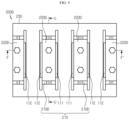
- FIG. 8 is a front schematically showing a battery module according to another embodiment of the present disclosure.
- FIG. 9 is a rear view schematically showing the battery module according to another embodiment of the present disclosure.
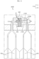
- FIG. 10 is a partial cross-sectioned view schematically showing the battery module, taken along the line D-D' of FIG. 8 .
- FIG. 11 is a vertical partial sectioned view schematically showing the battery module, taken along the line E-E' of FIG. 8 .
- the bus bar assembly 200C is different from the bus bar assembly 200A of FIG. 1 in view of the configuration of the connection bus bar 210C.
- the insert groove 212C formed at the connection bus bar 210C of the bus bar assembly 200C may be formed to extend from the left end 210C1 to the right end 210C2 of the front surface of the connection bus bar 210C.
- the insert groove 212C may be formed so that its portion recessed downwards (inwards) at the front surface of the connection bus bar 210C extends from the left end 210C1 to the right end 210C2.
- the bent end portion 111a of the electrode lead 111 inserted from the left side to the right side of the connection bus bar 210C and the bent end portion 111b of the electrode lead 111 inserted from the right side to the left side of the connection bus bar 210C may be located to be stacked at the insert groove 212C.
- a perforation hole H1 may be formed at the electrode lead 111 so that the fastening bolt 242 is inserted therein. That is, if the fastening member 240 ( FIG. 5 ) is inserted into the perforation hole H1, the plurality of the electrode leads 111 and the connection bus bar 210C may be integrally connected. Further, the perforation hole H1 may be formed at the stacked end portion of the electrode lead 111.
- two positive electrode leads 111 may be inserted from the left side to the right side of the connection bus bar 210C, and two end portions of the inserted positive electrode leads 111 may be stacked on each other and inserted into the insert groove 212C. Also, two positive electrode leads 111 may be inserted from the right side to the left side of the connection bus bar 210C, and two end portions of the inserted positive electrode leads 111 may be stacked on each other and inserted into the insert groove 212C.
- the end portions of two positive electrode leads 111 and the end portions of two positive electrode leads 111 may be disposed to be stacked on each other. Further, a perforation hole H1 may be formed at the stacked end portions of the positive electrode leads 111 so that the fastening bolt 242 is inserted therein.
- a fastening hole H2 and an insert hole H3 may be formed at the coupling bus bar 220C and the connection bus bar 210C, respectively, so that the cylindrical rod 242a of the fastening bolt 242 may be inserted therethrough. Further, the fastening bolt 242 may be inserted and fixed in the bus bar frame 230.
- the tightening force of the fastening bolt 242 may be directly transmitted to the electrode lead 111, thereby electrically connecting the electrode leads 110 more reliably.
- the recessed depth D3 of the insert groove 212C is equal to the entire thickness T3 of the end portions of the electrode leads 111 stacked in the insert groove 212C in the inserting direction.
- the recessed depth D3 of the insert groove 212C may be equal to the entire thickness T3 of the end portions of the electrode leads 110 stacked in the insert groove 212C in the inserting direction.
- the coupling bus bar 220C and the electrode lead 110 may contact each other more easily, and the electrode lead 110 may be effectively compressed to the insert groove 212C of the connection bus bar 210C by the coupling bus bar 220C, thereby improving the reliability of electrical connection.
- FIG. 12 is a partial cross-sectioned view schematically showing the battery module, taken along the line F-F' of FIG. 9 .
- FIG. 13 is a partial cross-sectioned view schematically showing the battery module, taken along the line G-G' of FIG. 9
- the negative electrode lead 112 may be inserted into the insert groove 212D from the left side to the right side of the connection bus bar 210D.
- the positive electrode lead 111 may be inserted into the insert groove 212D from the right side to the left side of the connection bus bar 210D.
- the bent end portion of the negative electrode lead 112 and the bent end portion of the positive electrode lead 111 may be disposed to be stacked on each other.
- a perforation hole H1 may be formed at the stacked end portions so that the fastening bolt 242 is inserted therein.
- connection bus bar 210D and the coupling bus bar 220D to effectively compress the electrode lead 110, it is needed that the front surface of the electrode lead 110, namely any one of the positive electrode lead 111 and the negative electrode lead 112 located at an uppermost side, stacked in the insert groove 212D is located on the same line as the non-recessed front surface of the connection bus bar 210D or to protrude further.
- the depth D4 recessed in the insert groove 212D is set to be equal to the stacked thickness T4 of the bent end portion of the negative electrode lead 112 and the bent end portion of the positive electrode lead 111.
- two negative electrode leads 112 may be inserted into the insert groove 212D from the left side to the right side of the connection bus bar 210D
- two positive electrode leads 111 may be inserted into the insert groove 212D from the right side to the left side of the connection bus bar 210D
- the end portions of the two negative electrode leads 112 and the end portions of the two positive electrode leads 111 may be stacked on each other.
- the recessed depth D4 of the insert groove 212D of the connection bus bar 210D may be set to be equal to the stacked thickness T4 of the bent end portion of the two negative electrode leads 112 and the bent end portion of the two positive electrode leads 111.
- the coupling bus bar 220D may effectively compress the electrode leads 110 inserted in the insert groove 212D, thereby enhancing the reliability of electrical connection securely fixing the electrode leads 110 to the insert groove 212D by the compression of the coupling bus bar 220D.
- bus bar assembly 200D of the present disclosure may have only one insert groove formed in the connection bus bar 220D, the manufacturing process may be simplified as compared with the bus bar assembly 200B of FIG. 3 .
- 300 battery module 220A, 220B: coupling bus bar 310: cell stack 225: compression protrusion 100: secondary battery 230: bus bar frame 110, 111, 112: electrode lead 240: fastening member H1: perforation hole 242: fastening bolt 200A to 200D: bus bar assembly 243: nut 210: connection bus bar 212: insert groove
- the present disclosure relates to a battery module including a bus bar assembly.
- the battery module of the present disclosure is applicable to a battery pack including a plurality of battery modules and electric components, and industries related to electronic devices, energy storage systems or vehicles including the battery pack.
Landscapes
- Chemical & Material Sciences (AREA)
- Chemical Kinetics & Catalysis (AREA)
- Electrochemistry (AREA)
- General Chemical & Material Sciences (AREA)
- Connection Of Batteries Or Terminals (AREA)
- Battery Mounting, Suspending (AREA)
Claims (7)
- Batteriemodul (300), umfassend:einen Zellenstapel (310), der durch Aufeinanderstapeln einer Vielzahl von beutelartigen Sekundärbatterien (100) mit Elektrodenleitungen (110) gebildet wird; undeine Busschienenanordnung (200A-200D), die so konfiguriert ist, dass sie die Vielzahl von Sekundärbatterien (100) elektrisch miteinander verbindet, und die eine Verbindungsstromschiene (210), die zwei oder mehr der Elektrodenleitungen (110) des Zellenstapels (310) kontaktiert, und eine Kopplungsstromschiene (220) einschließt, die mit der Verbindungsstromschiene (210) gekoppelt ist,wobei die Verbindungsstromschiene (210) und die Kopplungsstromschiene (220) eine Schienenform aufweisen, die sich in einer oberen und unteren Richtung erstreckt, und sowohl die Verbindungsstromschiene (210) als auch die Kopplungsstromschiene (220) eine vordere Oberfläche, eine hintere Oberfläche und seitliche Oberflächen einschließt,wobei die obere und untere Richtung eine Richtung in einer Längsrichtung der Verbindungsstromschiene (210) und der Kopplungsstromschiene (220) ist, eine Richtung in einer Breitenrichtung der Verbindungsstromschiene (210) und der Kopplungsstromschiene (220) eine linke und rechte Richtung ist, die die Stapelrichtung ist, und eine Richtung in einer Tiefenrichtung der Verbindungsstromschiene (210) und der Kopplungsstromschiene (220) eine vordere und hintere Richtung (F-Richtung) ist,wobei die Verbindungsstromschiene (210) mindestens eine Einsetznut (212) einschließt, die so ausgebildet ist, dass ein gebogener Endabschnitt von mindestens einer der Elektrodenleitungen (110) darin eingesetzt ist,die Einsetznut (212) an einer vorderen Oberfläche der Verbindungsstromschiene (210) ausgebildet ist,die Einsetznut (212) eine Struktur aufweist, die von einem vorderen Ende zu einem hinteren Ende der Verbindungsstromschiene (210) vertieft ist, undeine vertiefte Tiefe (D1-D4) der Einsetznut (212, 212B1, 212B2, 212C, 212D) gleich einer gesamten Dicke (T1-T4) der mindestens einen Elektrodenleitung (110) ist, die in die Einsetznut (212, 212B1, 212B2, 212C, 212D) in einer Einsetzrichtung eingesetzt ist, und die hintere Oberfläche der Kopplungsstromschiene (220) so ausgebildet ist, dass sie die kontaktierten Elektrodenleitungen (110) drückt, wobei die Busschienenanordnung (200A-200D) weiter einen Stromschienenrahmen (230) mit einer vorderen Oberfläche einschließt, auf der die Verbindungsstromschiene (210) geladen ist, wobei der Stromschienenrahmen (230) zwischen einem vorderen Abschnitt eines Körpers der Sekundärbatterie (100) und einem hinteren Abschnitt der Verbindungsstromschiene (210) angeordnet ist, wobei der Stromschienenrahmen (230) so konfiguriert ist, dass er ein Perforationsloch (H4) aufweist, durch das die Elektrodenleitung (110) des Zellenstapels (310) hindurchgeht, oder so, dass die Elektrodenleitung (110) an dem seitlichen Abschnitt des Stromschienenrahmens (230) vorbeigeht und nach vorne herausragt,wobei die Busschienenanordnung (200A-200D) weiter ein Befestigungselement (240) einschließt, das so konfiguriert ist, dass es die Verbindungsstromschiene (210) und die Kopplungsstromschiene (220) miteinander koppelt, und wobei das Befestigungselement (240) weiter einen Befestigungsbolzen (242) einschließt, der durch die Verbindungsstromschiene (210) und die Kopplungsstromschiene (220) eingesetzt ist, und eine zylindrische Stange (242a) des Befestigungsbolzens (242) in den Stromschienenrahmen (230) eingesetzt und befestigt ist.
- Batteriemodul (300) nach Anspruch 1,
wobei eine Breite der Einsetznut (212) in der oberen und unteren Richtung gleich oder größer ist als eine Länge der Elektrodenleitung (110), die in die Einsetznut (212) in der oberen und unteren Richtung eingesetzt ist. - Batteriemodul (300) nach Anspruch 1,wobei die Einsetznut (212C) so ausgebildet ist, dass sie sich von einem seitlichen Ende zu dem anderen seitlichen Ende einer vorderen Oberfläche der Verbindungsstromschiene (210C) erstreckt,wobei ein Perforationsloch (H1) an der Elektrodenleitung (110) ausgebildet ist, so dass der Befestigungsbolzen (242) darin eingesetzt wird, undwobei der gebogene Endabschnitt einer Elektrodenleitung (110), die von einer linken Seite zu einer rechten Seite der Verbindungsstromschiene (210C) eingesetzt ist, und der gebogene Endabschnitt einer Elektrodenleitung (110), die von einer rechten Seite zu einer linken Seite der Verbindungsstromschiene (210C) eingesetzt ist, in der Einsetznut (212C) aufeinander gestapelt sind.
- Batteriemodul (300) nach Anspruch 1,wobei die Einsetznut (212) in einer Mehrzahl an der Verbindungsstromschiene (210) ausgebildet ist,wobei ein Teil der Vielzahl von Einsetznuten (212) so ausgebildet ist, dass er sich von einem linken Ende (210a) zu einer Mitte der vorderen Oberfläche der Verbindungsstromschiene (210) erstreckt, und der andere Teil der Vielzahl von Einsetznuten (212) so ausgebildet ist, dass er sich von einem rechten Ende (210b) zu der Mitte der vorderen Oberfläche der Verbindungsstromschiene (210) erstreckt,wobei ein Endabschnitt der mindestens einen Elektrodenleitung (110), die von der linken Seite zu der rechten Seite der vorderen Oberfläche der Verbindungsstromschiene (210) eingesetzt wird, in die Einsetznut (212) eingesetzt wird, die so ausgebildet ist, dass sie sich von dem linken Ende (210a) zu der Mitte der vorderen Oberfläche der Verbindungsstromschiene (210) erstreckt, undwobei ein Endabschnitt der mindestens einen Elektrodenleitung (110), die von der rechten Seite zu der linken Seite der vorderen Oberfläche der Verbindungsstromschiene (210) eingesetzt wird, in die Einsetznut (212) eingesetzt wird, die so ausgebildet ist, dass sie sich von dem rechten Ende (210b) zu der Mitte der vorderen Oberfläche der Verbindungsstromschiene (210) erstreckt.
- Batteriemodul (300) nach Anspruch 4,wobei die Elektrodenleitung (110) eine positive Elektrodenleitung (111) und eine negative Elektrodenleitung (112) einschließt, undwobei eine Tiefe (D1) der Einsetznut (212B1), in die die positive Elektrodenleitung (111) eingesetzt wird, und eine Tiefe (D2) der Einsetznut (212B2), in die die negative Elektrodenleitung (112) eingesetzt wird, unterschiedlich sind.
- Batteriepack, umfassend mindestens ein Batteriemodul (300) nach mindestens einem der Ansprüche 1 bis 5.
- Fahrzeug, das den Batteriepack nach Anspruch 6 umfasst.
Applications Claiming Priority (2)
| Application Number | Priority Date | Filing Date | Title |
|---|---|---|---|
| KR1020170162867A KR102270266B1 (ko) | 2017-11-30 | 2017-11-30 | 버스바 어셈블리를 구비한 배터리 모듈 |
| PCT/KR2018/011967 WO2019107735A1 (ko) | 2017-11-30 | 2018-10-11 | 버스바 어셈블리를 구비한 배터리 모듈 |
Publications (3)
| Publication Number | Publication Date |
|---|---|
| EP3671902A1 EP3671902A1 (de) | 2020-06-24 |
| EP3671902A4 EP3671902A4 (de) | 2020-10-21 |
| EP3671902B1 true EP3671902B1 (de) | 2025-05-21 |
Family
ID=66664525
Family Applications (1)
| Application Number | Title | Priority Date | Filing Date |
|---|---|---|---|
| EP18884722.2A Active EP3671902B1 (de) | 2017-11-30 | 2018-10-11 | Batteriemodul mit busschienenanordnung |
Country Status (8)
| Country | Link |
|---|---|
| US (1) | US11289776B2 (de) |
| EP (1) | EP3671902B1 (de) |
| JP (1) | JP7045590B2 (de) |
| KR (1) | KR102270266B1 (de) |
| CN (1) | CN110692149B (de) |
| ES (1) | ES3032736T3 (de) |
| HU (1) | HUE071476T2 (de) |
| WO (1) | WO2019107735A1 (de) |
Families Citing this family (22)
| Publication number | Priority date | Publication date | Assignee | Title |
|---|---|---|---|---|
| KR102367381B1 (ko) * | 2018-12-26 | 2022-02-23 | 주식회사 엘지에너지솔루션 | 이물질 유입 방지 구조를 갖는 배터리 모듈, 이를 포함하는 배터리 팩 및 자동차 |
| KR102466503B1 (ko) * | 2019-06-11 | 2022-11-10 | 주식회사 엘지에너지솔루션 | 전지 모듈 및 그 제조 방법 |
| KR102541537B1 (ko) * | 2019-06-25 | 2023-06-08 | 주식회사 엘지에너지솔루션 | 전지 모듈 및 이를 포함하는 전지팩 |
| KR102785549B1 (ko) | 2019-08-02 | 2025-03-26 | 주식회사 엘지에너지솔루션 | 이동 가능한 버스바 조립체를 구비한 배터리 팩 및 이를 포함하는 이차전지 |
| KR102890284B1 (ko) * | 2019-10-01 | 2025-11-21 | 주식회사 엘지에너지솔루션 | 전지 모듈 및 그 제조 방법 |
| KR20210109824A (ko) | 2020-02-28 | 2021-09-07 | 주식회사 엘지에너지솔루션 | 전극 리드의 스프링 백 저지를 위한 버스바 프레임을 포함하는 배터리 모듈 및 이를 포함하는 배터리 팩 |
| KR102890288B1 (ko) * | 2020-04-29 | 2025-11-21 | 주식회사 엘지에너지솔루션 | 전지 모듈 및 이를 포함하는 전지팩 |
| KR102861724B1 (ko) * | 2020-07-21 | 2025-09-17 | 주식회사 엘지에너지솔루션 | 개선된 전극 리드 연결 구조를 갖는 배터리 모듈, 그리고 이를 포함하는 배터리 팩 및 자동차 |
| CN111933848B (zh) * | 2020-07-30 | 2022-09-20 | 国网甘肃省电力公司电力科学研究院 | 一种储能技术电池成组系统 |
| JP7462772B2 (ja) * | 2020-08-13 | 2024-04-05 | エルジー エナジー ソリューション リミテッド | 改善された電極リード接続構造を有するバッテリーモジュール、それを含むバッテリーパック及び自動車 |
| EP4109663B1 (de) * | 2020-10-23 | 2025-07-09 | LG Energy Solution, Ltd. | Batteriemodul mit sammelschiene mit gewindeabschnitt |
| KR102461833B1 (ko) * | 2020-12-09 | 2022-11-01 | 에스케이온 주식회사 | 배터리 모듈 |
| CN114649616A (zh) * | 2020-12-17 | 2022-06-21 | 比亚迪股份有限公司 | 动力电池以及用于动力电池的折叠连接片 |
| KR20220115390A (ko) * | 2021-02-10 | 2022-08-17 | 주식회사 엘지에너지솔루션 | 배터리 모듈, 배터리 팩, 및 자동차 |
| KR102707279B1 (ko) * | 2021-12-01 | 2024-09-19 | 주식회사 성우하이텍 | 배터리 모듈 어셈블리 |
| JP7551942B2 (ja) * | 2021-12-24 | 2024-09-17 | エルジー エナジー ソリューション リミテッド | 安全性が強化されたバッテリーモジュール |
| CN114696030B (zh) * | 2021-12-31 | 2025-07-08 | 陕西奥林波斯电力能源有限责任公司 | 一种大容量电池的整体结构 |
| CN115954620A (zh) * | 2022-08-25 | 2023-04-11 | 孚能科技(赣州)股份有限公司 | 电芯连接件及电池模组 |
| KR102562858B1 (ko) * | 2022-12-12 | 2023-08-02 | 주식회사 엠피에스티 | 고전류 충전 및 방전이 가능한 집전 장치 |
| CA3245832A1 (en) | 2022-12-19 | 2025-06-13 | Lg Energy Solution, Ltd. | BATTERY MODULE, BATTERY BLOCK, AND VEHICLE CONTAINING IT |
| JP2025089064A (ja) * | 2023-12-01 | 2025-06-12 | 豊田鉄工株式会社 | バッテリ装置 |
| KR20260014965A (ko) * | 2024-07-24 | 2026-02-02 | 주식회사 엘지에너지솔루션 | 버스바, 전지 모듈 및 전자 장치 |
Family Cites Families (34)
| Publication number | Priority date | Publication date | Assignee | Title |
|---|---|---|---|---|
| CN100355113C (zh) * | 2004-10-26 | 2007-12-12 | 日产自动车株式会社 | 组合电池 |
| JP2007265945A (ja) * | 2006-03-30 | 2007-10-11 | Tokyo R & D Co Ltd | ラミネートセル集積型バッテリ及びバッテリモジュール |
| WO2007121445A2 (en) * | 2006-04-18 | 2007-10-25 | Securaplane Technologies, Inc. | Battery busing scheme |
| KR100888284B1 (ko) | 2006-07-24 | 2009-03-10 | 주식회사 엘지화학 | 탭-리드 결합부의 전극간 저항차를 최소화한 전극조립체 및이를 포함하고 있는 전기화학 셀 |
| US7531270B2 (en) * | 2006-10-13 | 2009-05-12 | Enerdel, Inc. | Battery pack with integral cooling and bussing devices |
| CN101217190A (zh) * | 2007-01-04 | 2008-07-09 | 统振股份有限公司 | 电池组装板结构及其制造方法 |
| KR101140449B1 (ko) * | 2007-09-19 | 2012-04-30 | 에스케이이노베이션 주식회사 | 이차전지 모듈팩 |
| JP2009187972A (ja) | 2008-02-01 | 2009-08-20 | Fdk Corp | 蓄電モジュール |
| KR100993668B1 (ko) | 2008-08-01 | 2010-11-10 | 현대자동차일본기술연구소 | 배터리 셀의 전극 접속 구조 |
| JP2011198660A (ja) | 2010-03-20 | 2011-10-06 | Sanyo Electric Co Ltd | 電池パック |
| JP5615045B2 (ja) | 2010-05-28 | 2014-10-29 | 日本航空電子工業株式会社 | 電池間接続構造及び接続方法 |
| CN102064291B (zh) * | 2010-12-14 | 2013-04-10 | 长丰集团有限责任公司 | 一体压紧叠加式电池模块 |
| EP2672547B1 (de) | 2011-04-26 | 2017-05-31 | LG Chem, Ltd. | Busschiene mit einer neuartigen struktur sowie batteriemodul damit |
| KR101815876B1 (ko) * | 2011-04-28 | 2018-01-08 | 에스케이이노베이션 주식회사 | 과전류 방지장치를 포함한 배터리 팩 |
| US9472797B2 (en) * | 2011-05-25 | 2016-10-18 | Samsung Sdi Co., Ltd. | Battery pack |
| KR20120136542A (ko) | 2011-06-09 | 2012-12-20 | 인셀(주) | 파우치형 이차전지의 단자 연결 구조 |
| US8609276B2 (en) * | 2011-06-23 | 2013-12-17 | Samsung Sdi Co., Ltd. | Battery pack |
| KR20130019697A (ko) * | 2011-08-17 | 2013-02-27 | 삼성에스디아이 주식회사 | 전지 팩 및 이를 포함한 전지 모듈 |
| CN202282409U (zh) * | 2011-09-29 | 2012-06-20 | 北京神州远望科技有限公司 | 新型动力锂电池单元模块化结构 |
| JP2013084368A (ja) | 2011-10-06 | 2013-05-09 | Auto Network Gijutsu Kenkyusho:Kk | 電池モジュール |
| JP5916500B2 (ja) * | 2012-04-27 | 2016-05-11 | オートモーティブエナジーサプライ株式会社 | 組電池 |
| JP2014022195A (ja) * | 2012-07-18 | 2014-02-03 | Toshiba Corp | 組電池 |
| WO2014178130A1 (ja) * | 2013-05-01 | 2014-11-06 | 日立オートモティブシステムズ株式会社 | 角形電池及び組電池 |
| JP6011876B2 (ja) * | 2013-09-13 | 2016-10-19 | 株式会社オートネットワーク技術研究所 | 蓄電モジュール |
| JP6176126B2 (ja) * | 2014-01-21 | 2017-08-09 | 株式会社オートネットワーク技術研究所 | 配線モジュールおよび蓄電モジュール |
| WO2015152527A1 (ko) * | 2014-03-31 | 2015-10-08 | 주식회사 엘지화학 | 배터리 모듈 및 이를 포함하는 배터리 팩 |
| US10396334B2 (en) | 2014-03-31 | 2019-08-27 | Lg Chem, Ltd. | Battery module and battery pack comprising same |
| KR20150115250A (ko) * | 2014-04-03 | 2015-10-14 | 주식회사 엘지화학 | 내부 텐션-바를 포함하는 배터리 팩 |
| US9786894B2 (en) | 2014-11-03 | 2017-10-10 | Lg Chem, Ltd. | Battery pack |
| KR102381777B1 (ko) * | 2015-02-25 | 2022-04-01 | 삼성에스디아이 주식회사 | 배터리 팩 |
| KR101834506B1 (ko) | 2015-03-27 | 2018-03-05 | 주식회사 엘지화학 | 전지 모듈 |
| EP3118910B1 (de) * | 2015-07-15 | 2022-03-30 | Carl Freudenberg KG | Aufnahmeelement für pouch-zellen |
| KR102034208B1 (ko) | 2016-03-03 | 2019-10-18 | 주식회사 엘지화학 | 배터리 모듈, 이러한 배터리 모듈을 포함하는 배터리 팩 및 이러한 배터리 팩을 포함하는 자동차 |
| CN205900649U (zh) * | 2016-08-03 | 2017-01-18 | 无锡丰晟科技有限公司 | 一种软包锂电池模组 |
-
2017
- 2017-11-30 KR KR1020170162867A patent/KR102270266B1/ko active Active
-
2018
- 2018-10-11 WO PCT/KR2018/011967 patent/WO2019107735A1/ko not_active Ceased
- 2018-10-11 EP EP18884722.2A patent/EP3671902B1/de active Active
- 2018-10-11 US US16/620,385 patent/US11289776B2/en active Active
- 2018-10-11 CN CN201880036534.6A patent/CN110692149B/zh active Active
- 2018-10-11 JP JP2019564425A patent/JP7045590B2/ja active Active
- 2018-10-11 ES ES18884722T patent/ES3032736T3/es active Active
- 2018-10-11 HU HUE18884722A patent/HUE071476T2/hu unknown
Also Published As
| Publication number | Publication date |
|---|---|
| EP3671902A4 (de) | 2020-10-21 |
| US20200411832A1 (en) | 2020-12-31 |
| JP7045590B2 (ja) | 2022-04-01 |
| KR102270266B1 (ko) | 2021-06-28 |
| CN110692149A (zh) | 2020-01-14 |
| JP2020521288A (ja) | 2020-07-16 |
| WO2019107735A1 (ko) | 2019-06-06 |
| US11289776B2 (en) | 2022-03-29 |
| ES3032736T3 (en) | 2025-07-24 |
| KR20190063814A (ko) | 2019-06-10 |
| HUE071476T2 (hu) | 2025-08-28 |
| EP3671902A1 (de) | 2020-06-24 |
| CN110692149B (zh) | 2022-11-18 |
Similar Documents
| Publication | Publication Date | Title |
|---|---|---|
| EP3671902B1 (de) | Batteriemodul mit busschienenanordnung | |
| JP7045591B2 (ja) | バスバーアセンブリーを備えたバッテリーモジュール | |
| EP3671937B1 (de) | Batteriemodul enthaltend sensorbaugruppe und sammelschienenbaugruppe | |
| EP2693516B1 (de) | Batteriepackung | |
| EP3686956A1 (de) | Batteriemodul mit stromschiene und batteriesatz | |
| EP3624227B1 (de) | Batteriemodul mit verbesserter elektrischer verbindungsstabilität | |
| EP2645453B1 (de) | Wiederaufladbare Batterie | |
| US11450930B2 (en) | Battery module and battery pack having same | |
| JP6793841B2 (ja) | バッテリーモジュール、それを含むバッテリーパック及び自動車 | |
| EP2693511B1 (de) | Batteriepackung | |
| EP3561906B1 (de) | Batteriemodul | |
| EP3154108B1 (de) | Batteriemodul und batteriepack damit | |
| US8697265B2 (en) | Protection circuit module for secondary battery and battery pack having the same | |
| US20240250368A1 (en) | Battery Module Comprising Module Housing | |
| US9437845B2 (en) | Battery module and battery pack | |
| KR20220094758A (ko) | 배터리 모듈 | |
| CN110622340B (zh) | 电池组件以及电池组件的制造方法 |
Legal Events
| Date | Code | Title | Description |
|---|---|---|---|
| STAA | Information on the status of an ep patent application or granted ep patent |
Free format text: STATUS: THE INTERNATIONAL PUBLICATION HAS BEEN MADE |
|
| PUAI | Public reference made under article 153(3) epc to a published international application that has entered the european phase |
Free format text: ORIGINAL CODE: 0009012 |
|
| STAA | Information on the status of an ep patent application or granted ep patent |
Free format text: STATUS: REQUEST FOR EXAMINATION WAS MADE |
|
| 17P | Request for examination filed |
Effective date: 20200320 |
|
| AK | Designated contracting states |
Kind code of ref document: A1 Designated state(s): AL AT BE BG CH CY CZ DE DK EE ES FI FR GB GR HR HU IE IS IT LI LT LU LV MC MK MT NL NO PL PT RO RS SE SI SK SM TR |
|
| AX | Request for extension of the european patent |
Extension state: BA ME |
|
| A4 | Supplementary search report drawn up and despatched |
Effective date: 20200922 |
|
| RIC1 | Information provided on ipc code assigned before grant |
Ipc: H01M 2/20 20060101AFI20200916BHEP Ipc: H01M 2/10 20060101ALI20200916BHEP Ipc: H01M 2/26 20060101ALI20200916BHEP |
|
| STAA | Information on the status of an ep patent application or granted ep patent |
Free format text: STATUS: EXAMINATION IS IN PROGRESS |
|
| DAV | Request for validation of the european patent (deleted) | ||
| DAX | Request for extension of the european patent (deleted) | ||
| 17Q | First examination report despatched |
Effective date: 20210303 |
|
| RAP1 | Party data changed (applicant data changed or rights of an application transferred) |
Owner name: LG ENERGY SOLUTION LTD. |
|
| RAP3 | Party data changed (applicant data changed or rights of an application transferred) |
Owner name: LG ENERGY SOLUTION, LTD. |
|
| REG | Reference to a national code |
Ref legal event code: R079 Free format text: PREVIOUS MAIN CLASS: H01M0002200000 Ipc: H01M0050500000 Ref country code: DE Ref legal event code: R079 Ref document number: 602018082193 Country of ref document: DE Free format text: PREVIOUS MAIN CLASS: H01M0002200000 Ipc: H01M0050500000 |
|
| GRAP | Despatch of communication of intention to grant a patent |
Free format text: ORIGINAL CODE: EPIDOSNIGR1 |
|
| STAA | Information on the status of an ep patent application or granted ep patent |
Free format text: STATUS: GRANT OF PATENT IS INTENDED |
|
| INTG | Intention to grant announced |
Effective date: 20250214 |
|
| RIC1 | Information provided on ipc code assigned before grant |
Ipc: H01M 50/211 20210101ALI20250207BHEP Ipc: H01M 50/517 20210101ALI20250207BHEP Ipc: H01M 50/503 20210101ALI20250207BHEP Ipc: H01M 50/50 20210101AFI20250207BHEP |
|
| GRAS | Grant fee paid |
Free format text: ORIGINAL CODE: EPIDOSNIGR3 |
|
| GRAA | (expected) grant |
Free format text: ORIGINAL CODE: 0009210 |
|
| STAA | Information on the status of an ep patent application or granted ep patent |
Free format text: STATUS: THE PATENT HAS BEEN GRANTED |
|
| P01 | Opt-out of the competence of the unified patent court (upc) registered |
Free format text: CASE NUMBER: APP_14495/2025 Effective date: 20250325 |
|
| AK | Designated contracting states |
Kind code of ref document: B1 Designated state(s): AL AT BE BG CH CY CZ DE DK EE ES FI FR GB GR HR HU IE IS IT LI LT LU LV MC MK MT NL NO PL PT RO RS SE SI SK SM TR |
|
| REG | Reference to a national code |
Ref country code: GB Ref legal event code: FG4D |
|
| REG | Reference to a national code |
Ref country code: CH Ref legal event code: EP |
|
| REG | Reference to a national code |
Ref country code: DE Ref legal event code: R096 Ref document number: 602018082193 Country of ref document: DE |
|
| REG | Reference to a national code |
Ref country code: IE Ref legal event code: FG4D |
|
| REG | Reference to a national code |
Ref country code: ES Ref legal event code: FG2A Ref document number: 3032736 Country of ref document: ES Kind code of ref document: T3 Effective date: 20250724 |
|
| REG | Reference to a national code |
Ref country code: HU Ref legal event code: AG4A Ref document number: E071476 Country of ref document: HU |
|
| REG | Reference to a national code |
Ref country code: NL Ref legal event code: MP Effective date: 20250521 |
|
| PG25 | Lapsed in a contracting state [announced via postgrant information from national office to epo] |
Ref country code: FI Free format text: LAPSE BECAUSE OF FAILURE TO SUBMIT A TRANSLATION OF THE DESCRIPTION OR TO PAY THE FEE WITHIN THE PRESCRIBED TIME-LIMIT Effective date: 20250521 Ref country code: PT Free format text: LAPSE BECAUSE OF FAILURE TO SUBMIT A TRANSLATION OF THE DESCRIPTION OR TO PAY THE FEE WITHIN THE PRESCRIBED TIME-LIMIT Effective date: 20250922 |
|
| REG | Reference to a national code |
Ref country code: LT Ref legal event code: MG9D |
|
| PG25 | Lapsed in a contracting state [announced via postgrant information from national office to epo] |
Ref country code: NO Free format text: LAPSE BECAUSE OF FAILURE TO SUBMIT A TRANSLATION OF THE DESCRIPTION OR TO PAY THE FEE WITHIN THE PRESCRIBED TIME-LIMIT Effective date: 20250821 Ref country code: GR Free format text: LAPSE BECAUSE OF FAILURE TO SUBMIT A TRANSLATION OF THE DESCRIPTION OR TO PAY THE FEE WITHIN THE PRESCRIBED TIME-LIMIT Effective date: 20250822 |
|
| PG25 | Lapsed in a contracting state [announced via postgrant information from national office to epo] |
Ref country code: NL Free format text: LAPSE BECAUSE OF FAILURE TO SUBMIT A TRANSLATION OF THE DESCRIPTION OR TO PAY THE FEE WITHIN THE PRESCRIBED TIME-LIMIT Effective date: 20250521 Ref country code: PL Free format text: LAPSE BECAUSE OF FAILURE TO SUBMIT A TRANSLATION OF THE DESCRIPTION OR TO PAY THE FEE WITHIN THE PRESCRIBED TIME-LIMIT Effective date: 20250521 |
|
| PG25 | Lapsed in a contracting state [announced via postgrant information from national office to epo] |
Ref country code: BG Free format text: LAPSE BECAUSE OF FAILURE TO SUBMIT A TRANSLATION OF THE DESCRIPTION OR TO PAY THE FEE WITHIN THE PRESCRIBED TIME-LIMIT Effective date: 20250521 |
|
| PGFP | Annual fee paid to national office [announced via postgrant information from national office to epo] |
Ref country code: BE Payment date: 20250922 Year of fee payment: 8 Ref country code: GB Payment date: 20250922 Year of fee payment: 8 |
|
| PG25 | Lapsed in a contracting state [announced via postgrant information from national office to epo] |
Ref country code: HR Free format text: LAPSE BECAUSE OF FAILURE TO SUBMIT A TRANSLATION OF THE DESCRIPTION OR TO PAY THE FEE WITHIN THE PRESCRIBED TIME-LIMIT Effective date: 20250521 |
|
| PGFP | Annual fee paid to national office [announced via postgrant information from national office to epo] |
Ref country code: FR Payment date: 20250925 Year of fee payment: 8 |
|
| PG25 | Lapsed in a contracting state [announced via postgrant information from national office to epo] |
Ref country code: RS Free format text: LAPSE BECAUSE OF FAILURE TO SUBMIT A TRANSLATION OF THE DESCRIPTION OR TO PAY THE FEE WITHIN THE PRESCRIBED TIME-LIMIT Effective date: 20250821 |
|
| PG25 | Lapsed in a contracting state [announced via postgrant information from national office to epo] |
Ref country code: IS Free format text: LAPSE BECAUSE OF FAILURE TO SUBMIT A TRANSLATION OF THE DESCRIPTION OR TO PAY THE FEE WITHIN THE PRESCRIBED TIME-LIMIT Effective date: 20250921 |
|
| PG25 | Lapsed in a contracting state [announced via postgrant information from national office to epo] |
Ref country code: LV Free format text: LAPSE BECAUSE OF FAILURE TO SUBMIT A TRANSLATION OF THE DESCRIPTION OR TO PAY THE FEE WITHIN THE PRESCRIBED TIME-LIMIT Effective date: 20250521 |
|
| PGFP | Annual fee paid to national office [announced via postgrant information from national office to epo] |
Ref country code: HU Payment date: 20251029 Year of fee payment: 8 |
|
| REG | Reference to a national code |
Ref country code: AT Ref legal event code: MK05 Ref document number: 1797607 Country of ref document: AT Kind code of ref document: T Effective date: 20250521 |
|
| PGFP | Annual fee paid to national office [announced via postgrant information from national office to epo] |
Ref country code: DE Payment date: 20250922 Year of fee payment: 8 |
|
| PG25 | Lapsed in a contracting state [announced via postgrant information from national office to epo] |
Ref country code: SM Free format text: LAPSE BECAUSE OF FAILURE TO SUBMIT A TRANSLATION OF THE DESCRIPTION OR TO PAY THE FEE WITHIN THE PRESCRIBED TIME-LIMIT Effective date: 20250521 Ref country code: AT Free format text: LAPSE BECAUSE OF FAILURE TO SUBMIT A TRANSLATION OF THE DESCRIPTION OR TO PAY THE FEE WITHIN THE PRESCRIBED TIME-LIMIT Effective date: 20250521 Ref country code: DK Free format text: LAPSE BECAUSE OF FAILURE TO SUBMIT A TRANSLATION OF THE DESCRIPTION OR TO PAY THE FEE WITHIN THE PRESCRIBED TIME-LIMIT Effective date: 20250521 |
|
| PG25 | Lapsed in a contracting state [announced via postgrant information from national office to epo] |
Ref country code: CZ Free format text: LAPSE BECAUSE OF FAILURE TO SUBMIT A TRANSLATION OF THE DESCRIPTION OR TO PAY THE FEE WITHIN THE PRESCRIBED TIME-LIMIT Effective date: 20250521 |
|
| PG25 | Lapsed in a contracting state [announced via postgrant information from national office to epo] |
Ref country code: EE Free format text: LAPSE BECAUSE OF FAILURE TO SUBMIT A TRANSLATION OF THE DESCRIPTION OR TO PAY THE FEE WITHIN THE PRESCRIBED TIME-LIMIT Effective date: 20250521 |
|
| PG25 | Lapsed in a contracting state [announced via postgrant information from national office to epo] |
Ref country code: RO Free format text: LAPSE BECAUSE OF FAILURE TO SUBMIT A TRANSLATION OF THE DESCRIPTION OR TO PAY THE FEE WITHIN THE PRESCRIBED TIME-LIMIT Effective date: 20250521 Ref country code: SK Free format text: LAPSE BECAUSE OF FAILURE TO SUBMIT A TRANSLATION OF THE DESCRIPTION OR TO PAY THE FEE WITHIN THE PRESCRIBED TIME-LIMIT Effective date: 20250521 |
|
| PG25 | Lapsed in a contracting state [announced via postgrant information from national office to epo] |
Ref country code: IT Free format text: LAPSE BECAUSE OF FAILURE TO SUBMIT A TRANSLATION OF THE DESCRIPTION OR TO PAY THE FEE WITHIN THE PRESCRIBED TIME-LIMIT Effective date: 20250521 |
|
| PGFP | Annual fee paid to national office [announced via postgrant information from national office to epo] |
Ref country code: ES Payment date: 20251117 Year of fee payment: 8 |
|
| PLBE | No opposition filed within time limit |
Free format text: ORIGINAL CODE: 0009261 |
|
| STAA | Information on the status of an ep patent application or granted ep patent |
Free format text: STATUS: NO OPPOSITION FILED WITHIN TIME LIMIT |