EP3671367B1 - Anordnung aus einer halterung, einer platine und befestigungsmitteln, insbesondere für eine uhr - Google Patents
Anordnung aus einer halterung, einer platine und befestigungsmitteln, insbesondere für eine uhr Download PDFInfo
- Publication number
- EP3671367B1 EP3671367B1 EP18215659.6A EP18215659A EP3671367B1 EP 3671367 B1 EP3671367 B1 EP 3671367B1 EP 18215659 A EP18215659 A EP 18215659A EP 3671367 B1 EP3671367 B1 EP 3671367B1
- Authority
- EP
- European Patent Office
- Prior art keywords
- screw
- section
- recess
- plate
- housing
- Prior art date
- Legal status (The legal status is an assumption and is not a legal conclusion. Google has not performed a legal analysis and makes no representation as to the accuracy of the status listed.)
- Active
Links
Images

Classifications
-
- G—PHYSICS
- G04—HOROLOGY
- G04B—MECHANICALLY-DRIVEN CLOCKS OR WATCHES; MECHANICAL PARTS OF CLOCKS OR WATCHES IN GENERAL; TIME PIECES USING THE POSITION OF THE SUN, MOON OR STARS
- G04B29/00—Frameworks
- G04B29/02—Plates; Bridges; Cocks
- G04B29/022—Bridges
-
- G—PHYSICS
- G04—HOROLOGY
- G04B—MECHANICALLY-DRIVEN CLOCKS OR WATCHES; MECHANICAL PARTS OF CLOCKS OR WATCHES IN GENERAL; TIME PIECES USING THE POSITION OF THE SUN, MOON OR STARS
- G04B29/00—Frameworks
- G04B29/02—Plates; Bridges; Cocks
- G04B29/025—Cocks
-
- G—PHYSICS
- G04—HOROLOGY
- G04B—MECHANICALLY-DRIVEN CLOCKS OR WATCHES; MECHANICAL PARTS OF CLOCKS OR WATCHES IN GENERAL; TIME PIECES USING THE POSITION OF THE SUN, MOON OR STARS
- G04B29/00—Frameworks
- G04B29/02—Plates; Bridges; Cocks
- G04B29/027—Materials and manufacturing
-
- G—PHYSICS
- G04—HOROLOGY
- G04B—MECHANICALLY-DRIVEN CLOCKS OR WATCHES; MECHANICAL PARTS OF CLOCKS OR WATCHES IN GENERAL; TIME PIECES USING THE POSITION OF THE SUN, MOON OR STARS
- G04B29/00—Frameworks
- G04B29/04—Connecting or supporting parts
-
- F—MECHANICAL ENGINEERING; LIGHTING; HEATING; WEAPONS; BLASTING
- F16—ENGINEERING ELEMENTS AND UNITS; GENERAL MEASURES FOR PRODUCING AND MAINTAINING EFFECTIVE FUNCTIONING OF MACHINES OR INSTALLATIONS; THERMAL INSULATION IN GENERAL
- F16B—DEVICES FOR FASTENING OR SECURING CONSTRUCTIONAL ELEMENTS OR MACHINE PARTS TOGETHER, e.g. NAILS, BOLTS, CIRCLIPS, CLAMPS, CLIPS OR WEDGES; JOINTS OR JOINTING
- F16B25/00—Screws that cut thread in the body into which they are screwed, e.g. wood screws
- F16B25/001—Screws that cut thread in the body into which they are screwed, e.g. wood screws characterised by the material of the body into which the screw is screwed
- F16B25/0015—Screws that cut thread in the body into which they are screwed, e.g. wood screws characterised by the material of the body into which the screw is screwed the material being a soft organic material, e.g. wood or plastic
Definitions
- the present invention relates to the field of assemblies comprising a support, a plate and fixing means, in particular a watch movement support and a motor plate of a timepiece.
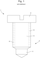
- FIG. 1 shows an example of a self-tapping screw 1 of the prior art.
- the screw 1 comprises an enlarged head 2 and a longitudinal body 3, of which a first section 4 arranged opposite the head 2 is smooth, and a second section 5 extending from the head 2 to the first section 4 is surrounded by a spiral thread 6.
- the first section 4 is narrower than the second section 5, and has a diameter close to that of the housing.
- the first section allows the screw to be positioned in the housing to keep it straight.
- the thread 6 gradually sinks into the wall of the housing, because the diameter of the second section with the thread 6 is wider than that of the housing.
- FR 1 234 518 A (FELDMAN) October 18, 1960 ( 1960-10-18 ) discloses the assembly of an upper plate 2 and a lower plate 1, the lower plate 1 comprising pillars 5 with holes in which self-tapping screws 5A are screwed into the housing receiving the screws.
- the body of the screw 5A has a conical shape and comprises a thread.
- screws are, for example, useful for assembling a watch movement support to a motor plate of a timepiece.
- housings are preformed without tapping, the support is positioned on the plate, and the screws are screwed into the housings.
- One of the two elements for example the plate, is provided with the housing(s), preferably made of a softer material than the metal screw, for example plastic.
- each screw taps a housing and assembles the two elements to each other.
- a first disadvantage of such a screw is that it is necessary to screw for a fairly long time to tap the housing and fix the screw there.
- the tapping is done little by little, because only part of the thread at the end of the second section forms the tapping.
- each screw requires a certain number of turns of the screw, and consequently a substantial handling time, whereas assembly must generally be quick.
- the first section only serves as a guide and does not tap the housing so that a part of the housing receiving the first section does not have the function of fixing the screw in the housing.
- the first section is short enough to avoid losing too much space, because the element must not be too thick, and take up too much space, which would be annoying for example in a watch case. Since the first section is short, the screw does not hold well in the housing before screwing, and easily risks coming out of the housing.
- the present invention aims in particular to overcome the various drawbacks of the devices known from the prior art.
- an objective of the invention is to provide an assembly that is easy and quick to assemble and which guarantees good retention of the support on the plate.
- the invention also aims to provide an assembly which is robust and inexpensive.
- the device is remarkable in that the predefined shape of the housing has a variable width, which is wider at the opening to a smaller diameter at the bottom of the housing, the shape corresponding to that of the screw body.
- the housing since the housing is wider at the opening than at the bottom of the housing, it adapts to the shape of the screw at several levels. On the one hand, a larger part of the screw can be inserted into the housing prior to screwing. The screw is better held in the housing, in a direction corresponding to that of the screwing. This feature facilitates screwing, because there is no need to hold the screw by hand or with an instrument to screw it, the screw being guided by the housing, without risk of coming out of the housing.
- the thread of the screw is more quickly in contact with the wall over the entire height of the body of the screw. Consequently, the screwing requires fewer turns to achieve complete screwing of the screw into the housing.
- the thread is arranged over the entire length of the body.
- the entire body of the screw serves for fixing. There is no part of the body of the screw in the housing without having the function of fixing to the housing, as in the state of the art described above.
- the body of the screw and the housing each have a cone shape, a base of one cone being arranged at the head for the screw, and a base of another cone being formed by the opening for the housing.
- the housing is closed at the bottom opposite the opening.
- the housing is extended by a retaining collar arranged beyond a second hole passing through the stator and the core of the motor, when the plate comprises the housing.
- the collar is wider than the second hole, so that the stator and the core are held to the plate.
- the housing is formed from a deformable material, for example plastic, such as polyethersulfone or polypropylene, optionally reinforced with glass fibers.
- the screw is made of metal.
- the body of the screw has a length substantially equal to the length of the housing and that of the first hole.
- the head is wider than the first hole.
- the head is wider than the first hole.
- the assembly comprises a motor module provided with the plate and a motor configured to move the clockwork movement carried by the support, the motor being provided with a coil core, a stator, and a motor activation circuit held by the plate.
- the assembly 10 comprises a support 30 for a watch movement of a timepiece, such as a wristwatch.
- the movement which is not shown in the figures, generally makes it possible to move hands on a dial of the timepiece.
- the assembly comprises a motor module provided with a plate 20 and a motor 31 configured to move the watch movement carried by the support 30.
- the motor 31 is provided with a stator 33 and a coil core 32 for activating a rotor, not shown in the figures, as well as an electronic control circuit 36 for the motor 31, and an activation circuit 35 for the coil for activating the rotation of the rotor.
- the stator 33, the core 32 and the activation circuit 35 are held under the plate 20, while the electronic control circuit 36 is arranged between the plate 20 and the support 30, when the plate 20 and the support 30 are assembled to each other.
- a spring 34 makes it possible to make a connection between the control circuit 36 and the activation circuit 35, to transmit an electric current and allow the coil to be activated.
- the spring 34 is arranged in a passage 37 through the plate to connect the two circuits.
- the assembly 10 further comprises means for fixing the support 30 to the plate 20.
- the fixing means comprise a self-tapping screw 11 and a housing 21 arranged in the plate 20, as well as a first hole 16 passing through the support 30.
- the screw 11 comprises a head 12 and a longitudinal body 15 about a first axis, the body 15 comprising an end 19 opposite the head 12 and a thread 9 arranged around the body 15.
- the head 12 comprises a plate 14 provided with a slot 13 allowing the screw to be rotated using a screwdriver.
- the slot 13 is straight in the figures, but it could also be cruciform or of another usual shape for a screw.
- the end 19 is here flat, but could also be pointed.
- the thread 9 has a helical shape with a predetermined pitch and width. The pitch of the thread has for example a value of 0.25 mm.
- the housing 21 is formed in the plate 20 of the motor about a second longitudinal axis.
- the housing 21 has a predefined shape comprising an inner wall 8 delimiting the shape, as well as an opening 7 for the passage of the screw 11.
- the housing 21 is preferably closed at the bottom 24 opposite the opening 7.
- the housing 21 is extended by a retaining collar 25 arranged beyond a second hole 26 made through the stator 33, the activation circuit 35 and the core 32 of the motor 31.
- the wall 8 of the housing 21 passes through the second hole 26, the bottom 24 of the housing 21 being formed in part by the collar 25.
- the collar 25 is wider than the second hole 26, so as to retain the stator 33, the activation circuit 35 and the core 32 against the plate.
- the first and second axes are substantially colinear after screwing, as well as prior to screwing, when the screw is partly positioned in the housing.
- the body 15 of the screw 11 has a length substantially equal to the length of the housing 21 and that of the first hole 16. This prevents the assembly from being too thick and taking up too much space, for example in a watch case.
- the screw 11 is configured to form a thread in the housing 21 when it is screwed inside the latter.
- the thread 9 is configured to sink into the wall 8 of the housing 21 during screwing.
- the body 15 and the thread 9 of the screw 11 are preferably made of a hard material while the wall 8 of the housing 21 is made of a softer material than that of the screw 11.
- the thread 9 of the screw 11 easily taps the wall 8 of the housing 21.
- the screw 11 is for example made of metal, preferably made of turned steel.
- the housing 21 is formed of a deformable material, for example made of plastic material, such as polyethersulfone or polypropylene, possibly reinforced with glass fibers.
- the body 15 of the screw 11 has a variable diameter along the first axis of the body, the body 15 being wider under the head 12 to a smaller diameter at the end 19.
- the predefined shape of the housing 21 has a variable width corresponding to that of the body 15, such that the predefined shape of the housing 21 and the body 15 of the screw 11 cooperate so that the body 15 of the screw 11 is held by the housing 21 over the entire height of the body 15 after screwing. Furthermore, the width of the screw 11 comprising the body 15 and the thread 9 is greater than that of the housing 21 at the same height, when the screw is screwed into the housing. Thus the thread 9 taps the housing 21, whatever its height on the body 15.
- the body 15 of the screw 11 is cylindrical and comprises at least two cylindrical sections 17, 18, a first section 17 extending from the end 19 of the body 15, and a second section 18 extending upstream of the first section 17, for example from the head 12 of the screw 11 to the first section 17.
- the second section 18 being wider than the first section.
- the shape of the housing 21 comprises at least two cylindrical sections, a first section 23 starting from the opening 7 of the housing, and a second section 22 deeper into the housing 21, the first section 23 being wider than the second section 22.
- the body of the screw and the housing can have three or four sections, or even more depending on the length of the screw.
- the variation in the width of the body 15 and the corresponding shape of the housing 21 allows a large part of the thread 9 to tap the housing 21 simultaneously.
- screwing is faster than with a conventional screw which taps the housing little by little with only one part of the thread.
- Time is saved because the screw requires less handling, i.e. fewer turns of the screw.
- a conventional self-tapping screw requires up to six turns of the screw, whereas a screw according to the invention requires only three turns.
- the screw 11 is well held by the housing 21 before screwing, thanks to the corresponding shapes of the screw 11 and that of the housing 21 according to the invention.
- a part of the body of the screw starting from the end can be inserted into a first part of the housing 21 to be held vertically before screwing.
- the first section 17 extending from the end 19 of the body 15 is inserted into the first section 23 starting from the opening 7 of the housing 21 without the thread taps the wall 8. This provides excellent support for the screw in the right direction before screwing, to avoid any risk of the screw falling out or being guided in the wrong direction.
- the width of the screw at the level of the first section 17 of the body 15 of the screw 11 with the thread 9, is substantially equal to the width of the first section 23 of the housing 21.
- the thread 9 is arranged over the entire length of the body 15.
- the entire body 15 of the screw 11 serves to tap the housing 21 and to fix the support 30 and the plate 20 together.
- the thread 9 is therefore arranged on the two cylindrical sections 17, 18 of the body 15. As shown in figure 3 after screwing, the first section 17 of the body 15 tapped the second section 22 of the housing 21, while the second section 18 of the body 15 tapped the first section 22 of the housing 21. The two tappings occurred simultaneously, which requires a fewer number of screw turns.
- screwing is even faster, because the tapping of each section of the housing is carried out simultaneously.
- the body of the screw and the housing each have a cone shape.
- the first cone of the body of the screw has a base arranged under the head for the screw, while the apex is arranged at the end of the body.
- the second cone formed by the housing has a base formed by the opening, the apex being formed by the bottom of the housing.
- the thread is preferably arranged over the entire height of the first cone.
- the present invention is not limited to the embodiments which have just been described and that various modifications and simple variants of the invention can be envisaged by those skilled in the art without departing from the scope of the invention as defined by the appended claims.
- the first hole is arranged in the plate and the housing is arranged in the support.
Landscapes
- Physics & Mathematics (AREA)
- General Physics & Mathematics (AREA)
- Engineering & Computer Science (AREA)
- General Engineering & Computer Science (AREA)
- Manufacturing & Machinery (AREA)
- Metallurgy (AREA)
- Life Sciences & Earth Sciences (AREA)
- Chemical & Material Sciences (AREA)
- Dispersion Chemistry (AREA)
- Wood Science & Technology (AREA)
- Mechanical Engineering (AREA)
- Connection Of Plates (AREA)
Claims (10)
- Baugruppe (10), die einen Träger (30) für ein Uhrwerk und eine Platine (20) mit einem Motor (31) für eine Uhr sowie Mittel zum Befestigen des Trägers (30) an der Platine (20) umfasst, wobei die Befestigungsmittel Folgendes umfassen:- eine selbstschneidende Schraube (11), die dazu konfiguriert ist, ein Gewinde zu bilden, wenn sie eingeschraubt wird, wobei die Schraube (11) einen Kopf (12) und einen Längskörper (15) umfasst, wobei der Körper (15) ein dem Kopf (12) gegenüberliegendes Ende (19) und ein um den Körper (15) herum angeordnetes Gewinde (9) umfasst, wobei der Körper einen entlang der ersten Achse des Körpers (15) variierenden Durchmesser aufweist, der am Kopf (12) breiter ist bis zu einem kleineren Durchmesser am Ende (19),- ein erstes Loch (16), das durch den Träger (30) oder die Platine (20) verläuft,- einen Sitz (21), der jeweils entsprechend der Anordnung des ersten Lochs (16) in der Platine (20) oder dem Träger (30) angeordnet ist, wobei der Sitz (21) eine Form aufweist, die durch eine Wand (8) und eine Öffnung (7) zum Aufnehmen des Körpers (15) der Schraube (11) definiert ist, dadurch gekennzeichnet, dass die Form des Sitzes (21) eine variable Breite aufweist, die an der Öffnung (7) breiter ist bis zu einem kleineren Durchmesser am Boden (24) des Sitzes (21), wobei die Form der des Körpers (15) der Schraube (11) entspricht,so dass, wenn der Körper (15) der Schraube (11) durch das erste Loch (16) hindurch verläuft, die vordefinierte Form des Sitzes (21) mit einem Gewinde versehen wird, wenn die Schraube in den Sitz eingeschraubt wird,wobei der Körper (15) der Schraube (11) zylindrisch ist und mindestens zwei zylindrische Abschnitte, einen ersten Abschnitt (17) am Ende (19) des Körpers (15) und einen zweiten Abschnitt (18) oberhalb des ersten Abschnitts (17), umfasst, wobei der zweite Abschnitt (18) breiter ist als der erste Abschnitt (17),und wobei der Sitz (21) mindestens zwei zylindrische Abschnitte, einen ersten Abschnitt (23), der sich von der Öffnung (7) des Sitzes (21) erstreckt, und einen zweiten Abschnitt (22), der tiefer in dem Sitz (21) ist, umfasst, wobei der erste Abschnitt (23) breiter ist als der zweite Abschnitt (22).
- Baugruppe nach Anspruch 1, dadurch gekennzeichnet, dass das Gewinde (9) entlang der gesamten Länge des Körpers (15) angeordnet ist.
- Baugruppe nach Anspruch 1 oder 2, dadurch gekennzeichnet, dass der Sitz (21) am Boden (24) gegenüber der Öffnung (7) geschlossen ist.
- Baugruppe nach einem der vorhergehenden Ansprüche, dadurch gekennzeichnet, dass der Sitz (21) durch einen Haltebördel (25) verlängert ist, der über ein zweites Loch (26) hinaus angeordnet ist, das durch den Stator (33) und den Kern (32) eines Motors verläuft, wenn die Platine (20) den Sitz (21) enthält.
- Baugruppe nach Anspruch 4, dadurch gekennzeichnet, dass der Bördel (25) breiter ist als das zweite Loch (26), so dass der Stator (33) und der Kern (32) gegen die Platine (20) gehalten werden.
- Baugruppe nach einem der vorhergehenden Ansprüche, dadurch gekennzeichnet, dass der Sitz (21) aus einem verformbaren Material, zum Beispiel Kunststoff, wie Polyethersulfon oder Polypropylen, ausgebildet ist und gegebenenfalls durch Glasfasern verstärkt ist.
- Baugruppe nach einem der vorhergehenden Ansprüche, dadurch gekennzeichnet, dass die Schraube (11) aus Metall ist.
- Baugruppe nach einem der vorhergehenden Ansprüche, dadurch gekennzeichnet, dass der Körper (15) der Schraube (11) eine Länge aufweist, die im Wesentlichen gleich der Länge des Sitzes (21) und der des ersten Lochs (16) ist.
- Baugruppe nach einem der vorhergehenden Ansprüche, dadurch gekennzeichnet, dass der Kopf (12) breiter ist als das erste Loch (16).
- Baugruppe nach einem der vorhergehenden Ansprüche, dadurch gekennzeichnet, dass sie ein Motormodul umfasst, das mit der Platine (20) und einem Motor (31) ausgestattet ist, der dazu konfiguriert ist, das von dem Träger (20) getragene Uhrwerk zu bewegen, wobei der Motor (31) mit einem Spulenkern (32), einem Stator (33) und einer Aktivierungsschaltung (35) des Motors (31) ausgestattet ist, die von der Platine (20) gehalten werden.
Priority Applications (4)
| Application Number | Priority Date | Filing Date | Title |
|---|---|---|---|
| EP18215659.6A EP3671367B1 (de) | 2018-12-21 | 2018-12-21 | Anordnung aus einer halterung, einer platine und befestigungsmitteln, insbesondere für eine uhr |
| JP2019224235A JP7029435B2 (ja) | 2018-12-21 | 2019-12-12 | 特に時計のための、サポート、プレートおよび締付け手段を備えるアセンブリ |
| US16/715,473 US11674542B2 (en) | 2018-12-21 | 2019-12-16 | Assembly comprising a support, a plate and fastening means, in particular for a timepiece |
| CN201911327097.6A CN111352331B (zh) | 2018-12-21 | 2019-12-20 | 包括支架、主夹板和紧固装置的组件、特别是用于时计的组件 |
Applications Claiming Priority (1)
| Application Number | Priority Date | Filing Date | Title |
|---|---|---|---|
| EP18215659.6A EP3671367B1 (de) | 2018-12-21 | 2018-12-21 | Anordnung aus einer halterung, einer platine und befestigungsmitteln, insbesondere für eine uhr |
Publications (2)
| Publication Number | Publication Date |
|---|---|
| EP3671367A1 EP3671367A1 (de) | 2020-06-24 |
| EP3671367B1 true EP3671367B1 (de) | 2025-01-29 |
Family
ID=64901891
Family Applications (1)
| Application Number | Title | Priority Date | Filing Date |
|---|---|---|---|
| EP18215659.6A Active EP3671367B1 (de) | 2018-12-21 | 2018-12-21 | Anordnung aus einer halterung, einer platine und befestigungsmitteln, insbesondere für eine uhr |
Country Status (4)
| Country | Link |
|---|---|
| US (1) | US11674542B2 (de) |
| EP (1) | EP3671367B1 (de) |
| JP (1) | JP7029435B2 (de) |
| CN (1) | CN111352331B (de) |
Citations (2)
| Publication number | Priority date | Publication date | Assignee | Title |
|---|---|---|---|---|
| JP3446113B2 (ja) * | 1997-05-09 | 2003-09-16 | 株式会社サンノハシ | 2部材締結方法及びその方法に用いるボルト |
| EP1804142A1 (de) * | 2005-12-28 | 2007-07-04 | ETA SA Manufacture Horlogère Suisse | Mechanische Uhr mit Vorrichtung zur Einstellung des Spieles eines Drehteiles |
Family Cites Families (49)
| Publication number | Priority date | Publication date | Assignee | Title |
|---|---|---|---|---|
| US2167558A (en) * | 1937-06-24 | 1939-07-25 | Lamson & Sessions Co | Self-tapping bolt |
| US3020702A (en) * | 1958-09-02 | 1962-02-13 | Feldman Lawrence | Timepiece movement |
| DE7324375U (de) * | 1973-06-30 | 1973-09-27 | Gebrueder Junghans Gmbh | Baugruppe für elektrisch angetriebene Gangregler |
| JPS5149064U (de) | 1974-10-11 | 1976-04-13 | ||
| US4463753A (en) * | 1980-01-04 | 1984-08-07 | Gustilo Ramon B | Compression bone screw |
| FR2509813A1 (fr) * | 1981-07-16 | 1983-01-21 | Tourolle Et Fils Rene | Tourillon de montage de deux pieces |
| GB2112549A (en) * | 1981-12-24 | 1983-07-20 | Textron Inc | Electronic watch assembly |
| GB2202994B (en) * | 1987-03-05 | 1991-04-24 | Seiko Epson Corp | Circuit assembly, e.g. for an electronic timepiece |
| CN2181702Y (zh) | 1993-09-29 | 1994-11-02 | 鄞县天童仪表厂 | 自套螺纹摆轴承螺钉 |
| DE69403612T2 (de) * | 1993-11-23 | 1998-01-08 | Ebauchesfabrik Eta Ag | Uhr mit einer Vorrichtung zur Befestigung eines abnehmbaren Elementes an einen Träger und Verfahren zum Befestigen dieses Elementes an diesen Träger |
| JP3319175B2 (ja) * | 1994-09-28 | 2002-08-26 | セイコーエプソン株式会社 | 時 計 |
| JP3633145B2 (ja) * | 1996-10-11 | 2005-03-30 | カシオ計算機株式会社 | 腕時計 |
| US6349758B1 (en) * | 1998-01-13 | 2002-02-26 | Louis E. Bell | Apparatus for forming a pour hole and main sprue in an investment mold for lost wax casting |
| DE29819813U1 (de) * | 1998-11-05 | 2000-03-09 | Hettich & Co., 78713 Schramberg | Gewindeschneidende Schraube |
| JP4362160B2 (ja) | 1999-02-26 | 2009-11-11 | シチズンホールディングス株式会社 | 腕時計ケース |
| TWM266371U (en) * | 1999-10-29 | 2005-06-01 | Jone Edland | System comprising a screw and a tool therefor |
| US7070376B1 (en) * | 1999-12-14 | 2006-07-04 | Simpson Strong-Tie Company, Inc. | Self-drilling, self-anchoring fastener for concrete |
| US6966737B2 (en) | 2001-08-06 | 2005-11-22 | Olympic Manufacturing Group, Inc. | Deck screws suitable for use with composite lumber |
| JP3433749B2 (ja) | 2002-05-07 | 2003-08-04 | セイコーエプソン株式会社 | 時 計 |
| ATE324621T1 (de) * | 2002-10-04 | 2006-05-15 | Eta Sa Mft Horlogere Suisse | Kupplungsmechanismus für chronographen |
| DE60220811T2 (de) * | 2002-12-31 | 2008-03-06 | Eta Sa Manufacture Horlogère Suisse | Betätigungsvorrichtung mit mehreren axialen Stellungen für ein elektronisches Gerät |
| CN2689300Y (zh) * | 2003-12-29 | 2005-03-30 | 吴家骏 | 带往复转动饰物的座钟装置 |
| DE06405114T1 (de) | 2006-03-15 | 2008-04-24 | Doniar S.A. | LIGA Verfahren zur Herstellung einer einzel- oder mehrlagigen metallischen Struktur und damit hergestellte Struktur |
| JP4742007B2 (ja) * | 2006-10-11 | 2011-08-10 | 株式会社トープラ | タッピンねじ用皮膜形成剤、同皮膜形成剤を用いてタッピンねじの外周を被覆する皮膜を形成する皮膜形成方法、および、同皮膜形成剤にて形成された皮膜付きタッピンねじ |
| FR2914379B1 (fr) * | 2007-03-29 | 2011-07-15 | Sotralu | Dispositif d'assemblage par vis d'au moins une piece regide sur un support et ouvrant equipe d'un tel dispositif. |
| FR2916624B1 (fr) * | 2007-05-29 | 2009-08-21 | Small Bone Innovations Interna | Vis a os, notamment d'osteosynthese |
| JP4538483B2 (ja) | 2007-10-23 | 2010-09-08 | 株式会社カシオ日立モバイルコミュニケーションズ | 防水構造及び電子機器 |
| JP2009217047A (ja) | 2008-03-11 | 2009-09-24 | Olympus Imaging Corp | デジタルカメラ |
| EP2444862A3 (de) * | 2009-07-10 | 2013-04-24 | Chopard Technologies SA | Positionsregulierungsverfahren eines Bauteils auf einer Unterlage |
| IT1403796B1 (it) * | 2011-01-12 | 2013-10-31 | Savio Spa | "sistema di fissaggio di accessori su telai in materiale metallico per porte, finestre e simili" |
| EP2595007B1 (de) * | 2011-11-17 | 2015-01-07 | ETA SA Manufacture Horlogère Suisse | Uhrwerksanordnung mit Zentrierung und Befestigung einer Platine auf einem Gehäuserahmen |
| CN202597398U (zh) * | 2012-06-15 | 2012-12-12 | 宁波腾玲工贸有限公司 | 紧固螺栓 |
| CN102767361A (zh) * | 2012-07-25 | 2012-11-07 | 陈明增 | 智能液压悬绳装置及工作方法 |
| US20160076576A1 (en) | 2012-12-09 | 2016-03-17 | Shilo Technologies Ltd. | Disposable aligner for self-tapping threaded insert |
| FR3006943B1 (fr) * | 2013-06-18 | 2016-02-26 | Peugeot Citroen Automobiles Sa | Procede de realisation d'un berceau avant de vehicule, et berceau avant de vehicule obtenu par ce procede. |
| FR3008754B1 (fr) | 2013-07-19 | 2015-09-04 | Lisi Aerospace | Fixation metallique |
| CN203730503U (zh) * | 2014-03-13 | 2014-07-23 | 温州市强杰不锈钢标准件有限公司 | 一种自攻螺钉 |
| CN204533126U (zh) * | 2014-12-29 | 2015-08-05 | 温州万兆汽车零部件有限公司 | 扁方铆接螺栓 |
| JP6380116B2 (ja) * | 2015-01-14 | 2018-08-29 | カシオ計算機株式会社 | 運針機構及び時計 |
| CN204572689U (zh) | 2015-02-13 | 2015-08-19 | 美联钢结构建筑系统(上海)股份有限公司 | 用于钢结构围护系统的限位紧固螺钉 |
| CN204631455U (zh) | 2015-05-20 | 2015-09-09 | 福建上润精密仪器有限公司 | 一种石英手表机芯步进电机锁紧固定结构 |
| CN205063345U (zh) * | 2015-09-30 | 2016-03-02 | 青岛煜堃机械有限公司 | 管道预留孔预留器 |
| CN105661772A (zh) * | 2016-03-29 | 2016-06-15 | 深圳市川楚科技开发有限公司 | 一种手表 |
| CN106013669B (zh) * | 2016-06-27 | 2019-02-19 | 浙江华夏杰高分子建材有限公司 | 墙板的安装结构及安装方法 |
| EP3361324A1 (de) | 2017-02-13 | 2018-08-15 | Rolex Sa | Steckverschlusssystem für uhr |
| DE102017108225A1 (de) * | 2017-04-18 | 2018-10-18 | Adolf Würth Gmbh & Co Kg | Holzschraube mit bogenförmigem Überstand zwischen Gewindegängen |
| CN108167302A (zh) * | 2017-11-17 | 2018-06-15 | 江苏壹鼎崮机电科技有限公司 | 一种防松螺栓 |
| CN207814161U (zh) * | 2017-12-30 | 2018-09-04 | 昆山中固精密五金有限公司 | 一种支杆螺丝 |
| US11454932B2 (en) * | 2018-07-24 | 2022-09-27 | The Swatch Group Research And Development Ltd | Method for making a flexure bearing mechanism for a mechanical timepiece oscillator |
-
2018
- 2018-12-21 EP EP18215659.6A patent/EP3671367B1/de active Active
-
2019
- 2019-12-12 JP JP2019224235A patent/JP7029435B2/ja active Active
- 2019-12-16 US US16/715,473 patent/US11674542B2/en active Active
- 2019-12-20 CN CN201911327097.6A patent/CN111352331B/zh active Active
Patent Citations (2)
| Publication number | Priority date | Publication date | Assignee | Title |
|---|---|---|---|---|
| JP3446113B2 (ja) * | 1997-05-09 | 2003-09-16 | 株式会社サンノハシ | 2部材締結方法及びその方法に用いるボルト |
| EP1804142A1 (de) * | 2005-12-28 | 2007-07-04 | ETA SA Manufacture Horlogère Suisse | Mechanische Uhr mit Vorrichtung zur Einstellung des Spieles eines Drehteiles |
Non-Patent Citations (1)
| Title |
|---|
| ANONYMOUS: "Histoire des vis autoperçeuses Faynot", 14 April 2021 (2021-04-14), pages 1 - 12, XP055930036, Retrieved from the Internet <URL:https://www.faynot.com/histoire-vis-autoperceuse/> [retrieved on 20220610] * |
Also Published As
| Publication number | Publication date |
|---|---|
| JP2020101540A (ja) | 2020-07-02 |
| JP7029435B2 (ja) | 2022-03-03 |
| EP3671367A1 (de) | 2020-06-24 |
| CN111352331A (zh) | 2020-06-30 |
| CN111352331B (zh) | 2022-07-08 |
| US20200200205A1 (en) | 2020-06-25 |
| US11674542B2 (en) | 2023-06-13 |
Similar Documents
| Publication | Publication Date | Title |
|---|---|---|
| EP3574377B1 (de) | Uhrengehäuse mit einer kapsel, die durch eine hintere lunette in einem mittelteil gehalten ist | |
| EP2592500B1 (de) | Armbanduhrengehäuse, das ein Kronrad mit Ausrichtungsgedächtnis umfasst | |
| EP2290477B1 (de) | Einheit zur Befestigung des peripheren Endes der Spirale einer Vorrichtung mit Spiralunruh für ein Uhrwerk | |
| EP1173074B1 (de) | Armband mit lösbaren gliedern | |
| EP2196866B1 (de) | Assembly comprising a ratchet-wheel fixed to the barrel-arbor and barrel-arbor for this assembly | |
| EP2915445B1 (de) | Vorrichtung und Verfahren zum drehbaren Zusammenbau von mindestens zwei Teilen, und Einheit aus den zwei zusammengebauten Teilen | |
| EP3671367B1 (de) | Anordnung aus einer halterung, einer platine und befestigungsmitteln, insbesondere für eine uhr | |
| EP3401740A1 (de) | Uhrkomponente zum einpressen ohne gratbildung | |
| EP0892944B1 (de) | Uhr | |
| CH715693A2 (fr) | Assemblage comprenant un support, une platine et des moyens de fixation, notamment pour une pièce d'horlogerie. | |
| CH691632A5 (fr) | Montre à tige de remontoir et de mise à l'heure en deux parties. | |
| EP1637940B1 (de) | Spiralrolle für Uhren | |
| FR2524031A1 (fr) | Perfectionnements aux dispositifs d'ancrage destines a etre enfonces dans le sol | |
| FR2943748A1 (fr) | Assemblage visse pour l'assemblage fixe de deux sous-ensembles | |
| CH717211A2 (fr) | Couronne pour boîte de pièce d'horlogerie, tige pour mouvement horloger et pièce d'horlogerie. | |
| EP1558972B1 (de) | Vorrichtung zur kupplung eines zahnrades | |
| EP3004483A1 (de) | Bewehrungsstab mit hoher haftfestigkeit für stahlbeton | |
| EP0276688B1 (de) | Handsteuerungsvorrichtung für ein in einem Gehäuse eingebautes Uhrwerk | |
| EP3470932B1 (de) | Oszillator für uhrwerk | |
| FR2549615A3 (fr) | Selecteur de programmes pour minuterie | |
| CH694444A5 (fr) | Rotor pour moteur électromagnétique. | |
| CH716842B1 (fr) | Dispositif d'assemblage d'un indicateur, indicateur, mécanisme de tourbillon les comprenant, son procédé de montage et pièce d'horlogerie. | |
| EP2123919A1 (de) | Starre Verbindung von Rohrteilen | |
| WO1997037609A1 (fr) | Faux moignon destine a servir de base pour la realisation d'une prothese dentaire | |
| CH208578A (fr) | Pont de balancier avec raquette. |
Legal Events
| Date | Code | Title | Description |
|---|---|---|---|
| PUAI | Public reference made under article 153(3) epc to a published international application that has entered the european phase |
Free format text: ORIGINAL CODE: 0009012 |
|
| STAA | Information on the status of an ep patent application or granted ep patent |
Free format text: STATUS: THE APPLICATION HAS BEEN PUBLISHED |
|
| AK | Designated contracting states |
Kind code of ref document: A1 Designated state(s): AL AT BE BG CH CY CZ DE DK EE ES FI FR GB GR HR HU IE IS IT LI LT LU LV MC MK MT NL NO PL PT RO RS SE SI SK SM TR |
|
| AX | Request for extension of the european patent |
Extension state: BA ME |
|
| STAA | Information on the status of an ep patent application or granted ep patent |
Free format text: STATUS: REQUEST FOR EXAMINATION WAS MADE |
|
| 17P | Request for examination filed |
Effective date: 20210111 |
|
| RBV | Designated contracting states (corrected) |
Designated state(s): AL AT BE BG CH CY CZ DE DK EE ES FI FR GB GR HR HU IE IS IT LI LT LU LV MC MK MT NL NO PL PT RO RS SE SI SK SM TR |
|
| STAA | Information on the status of an ep patent application or granted ep patent |
Free format text: STATUS: EXAMINATION IS IN PROGRESS |
|
| 17Q | First examination report despatched |
Effective date: 20220617 |
|
| P01 | Opt-out of the competence of the unified patent court (upc) registered |
Effective date: 20230701 |
|
| RIC1 | Information provided on ipc code assigned before grant |
Ipc: F16B 25/00 20060101ALI20240613BHEP Ipc: G04B 29/04 20060101AFI20240613BHEP |
|
| GRAP | Despatch of communication of intention to grant a patent |
Free format text: ORIGINAL CODE: EPIDOSNIGR1 |
|
| STAA | Information on the status of an ep patent application or granted ep patent |
Free format text: STATUS: GRANT OF PATENT IS INTENDED |
|
| INTG | Intention to grant announced |
Effective date: 20240719 |
|
| GRAJ | Information related to disapproval of communication of intention to grant by the applicant or resumption of examination proceedings by the epo deleted |
Free format text: ORIGINAL CODE: EPIDOSDIGR1 |
|
| STAA | Information on the status of an ep patent application or granted ep patent |
Free format text: STATUS: EXAMINATION IS IN PROGRESS |
|
| INTC | Intention to grant announced (deleted) | ||
| GRAS | Grant fee paid |
Free format text: ORIGINAL CODE: EPIDOSNIGR3 |
|
| STAA | Information on the status of an ep patent application or granted ep patent |
Free format text: STATUS: GRANT OF PATENT IS INTENDED |
|
| GRAP | Despatch of communication of intention to grant a patent |
Free format text: ORIGINAL CODE: EPIDOSNIGR1 |
|
| GRAA | (expected) grant |
Free format text: ORIGINAL CODE: 0009210 |
|
| STAA | Information on the status of an ep patent application or granted ep patent |
Free format text: STATUS: THE PATENT HAS BEEN GRANTED |
|
| INTG | Intention to grant announced |
Effective date: 20241203 |
|
| AK | Designated contracting states |
Kind code of ref document: B1 Designated state(s): AL AT BE BG CH CY CZ DE DK EE ES FI FR GB GR HR HU IE IS IT LI LT LU LV MC MK MT NL NO PL PT RO RS SE SI SK SM TR |
|
| REG | Reference to a national code |
Ref country code: GB Ref legal event code: FG4D Free format text: NOT ENGLISH |
|
| REG | Reference to a national code |
Ref country code: CH Ref legal event code: EP |
|
| REG | Reference to a national code |
Ref country code: DE Ref legal event code: R096 Ref document number: 602018078825 Country of ref document: DE |
|
| REG | Reference to a national code |
Ref country code: IE Ref legal event code: FG4D Free format text: LANGUAGE OF EP DOCUMENT: FRENCH |
|
| REG | Reference to a national code |
Ref country code: NL Ref legal event code: MP Effective date: 20250129 |
|
| PG25 | Lapsed in a contracting state [announced via postgrant information from national office to epo] |
Ref country code: NL Free format text: LAPSE BECAUSE OF FAILURE TO SUBMIT A TRANSLATION OF THE DESCRIPTION OR TO PAY THE FEE WITHIN THE PRESCRIBED TIME-LIMIT Effective date: 20250129 |
|
| PG25 | Lapsed in a contracting state [announced via postgrant information from national office to epo] |
Ref country code: RS Free format text: LAPSE BECAUSE OF FAILURE TO SUBMIT A TRANSLATION OF THE DESCRIPTION OR TO PAY THE FEE WITHIN THE PRESCRIBED TIME-LIMIT Effective date: 20250429 |
|
| PG25 | Lapsed in a contracting state [announced via postgrant information from national office to epo] |
Ref country code: FI Free format text: LAPSE BECAUSE OF FAILURE TO SUBMIT A TRANSLATION OF THE DESCRIPTION OR TO PAY THE FEE WITHIN THE PRESCRIBED TIME-LIMIT Effective date: 20250129 |
|
| PG25 | Lapsed in a contracting state [announced via postgrant information from national office to epo] |
Ref country code: PL Free format text: LAPSE BECAUSE OF FAILURE TO SUBMIT A TRANSLATION OF THE DESCRIPTION OR TO PAY THE FEE WITHIN THE PRESCRIBED TIME-LIMIT Effective date: 20250129 |
|
| PG25 | Lapsed in a contracting state [announced via postgrant information from national office to epo] |
Ref country code: ES Free format text: LAPSE BECAUSE OF FAILURE TO SUBMIT A TRANSLATION OF THE DESCRIPTION OR TO PAY THE FEE WITHIN THE PRESCRIBED TIME-LIMIT Effective date: 20250129 |
|
| REG | Reference to a national code |
Ref country code: LT Ref legal event code: MG9D |
|
| PG25 | Lapsed in a contracting state [announced via postgrant information from national office to epo] |
Ref country code: NO Free format text: LAPSE BECAUSE OF FAILURE TO SUBMIT A TRANSLATION OF THE DESCRIPTION OR TO PAY THE FEE WITHIN THE PRESCRIBED TIME-LIMIT Effective date: 20250429 Ref country code: IS Free format text: LAPSE BECAUSE OF FAILURE TO SUBMIT A TRANSLATION OF THE DESCRIPTION OR TO PAY THE FEE WITHIN THE PRESCRIBED TIME-LIMIT Effective date: 20250529 |
|
| REG | Reference to a national code |
Ref country code: AT Ref legal event code: MK05 Ref document number: 1764044 Country of ref document: AT Kind code of ref document: T Effective date: 20250129 |
|
| PG25 | Lapsed in a contracting state [announced via postgrant information from national office to epo] |
Ref country code: HR Free format text: LAPSE BECAUSE OF FAILURE TO SUBMIT A TRANSLATION OF THE DESCRIPTION OR TO PAY THE FEE WITHIN THE PRESCRIBED TIME-LIMIT Effective date: 20250129 |
|
| PG25 | Lapsed in a contracting state [announced via postgrant information from national office to epo] |
Ref country code: LV Free format text: LAPSE BECAUSE OF FAILURE TO SUBMIT A TRANSLATION OF THE DESCRIPTION OR TO PAY THE FEE WITHIN THE PRESCRIBED TIME-LIMIT Effective date: 20250129 Ref country code: PT Free format text: LAPSE BECAUSE OF FAILURE TO SUBMIT A TRANSLATION OF THE DESCRIPTION OR TO PAY THE FEE WITHIN THE PRESCRIBED TIME-LIMIT Effective date: 20250529 |
|
| PG25 | Lapsed in a contracting state [announced via postgrant information from national office to epo] |
Ref country code: GR Free format text: LAPSE BECAUSE OF FAILURE TO SUBMIT A TRANSLATION OF THE DESCRIPTION OR TO PAY THE FEE WITHIN THE PRESCRIBED TIME-LIMIT Effective date: 20250430 Ref country code: BG Free format text: LAPSE BECAUSE OF FAILURE TO SUBMIT A TRANSLATION OF THE DESCRIPTION OR TO PAY THE FEE WITHIN THE PRESCRIBED TIME-LIMIT Effective date: 20250129 |
|
| PG25 | Lapsed in a contracting state [announced via postgrant information from national office to epo] |
Ref country code: AT Free format text: LAPSE BECAUSE OF FAILURE TO SUBMIT A TRANSLATION OF THE DESCRIPTION OR TO PAY THE FEE WITHIN THE PRESCRIBED TIME-LIMIT Effective date: 20250129 |
|
| PG25 | Lapsed in a contracting state [announced via postgrant information from national office to epo] |
Ref country code: SE Free format text: LAPSE BECAUSE OF FAILURE TO SUBMIT A TRANSLATION OF THE DESCRIPTION OR TO PAY THE FEE WITHIN THE PRESCRIBED TIME-LIMIT Effective date: 20250129 |
|
| PG25 | Lapsed in a contracting state [announced via postgrant information from national office to epo] |
Ref country code: SM Free format text: LAPSE BECAUSE OF FAILURE TO SUBMIT A TRANSLATION OF THE DESCRIPTION OR TO PAY THE FEE WITHIN THE PRESCRIBED TIME-LIMIT Effective date: 20250129 |
|
| PG25 | Lapsed in a contracting state [announced via postgrant information from national office to epo] |
Ref country code: DK Free format text: LAPSE BECAUSE OF FAILURE TO SUBMIT A TRANSLATION OF THE DESCRIPTION OR TO PAY THE FEE WITHIN THE PRESCRIBED TIME-LIMIT Effective date: 20250129 |
|
| PG25 | Lapsed in a contracting state [announced via postgrant information from national office to epo] |
Ref country code: IT Free format text: LAPSE BECAUSE OF FAILURE TO SUBMIT A TRANSLATION OF THE DESCRIPTION OR TO PAY THE FEE WITHIN THE PRESCRIBED TIME-LIMIT Effective date: 20250129 |
|
| PG25 | Lapsed in a contracting state [announced via postgrant information from national office to epo] |
Ref country code: EE Free format text: LAPSE BECAUSE OF FAILURE TO SUBMIT A TRANSLATION OF THE DESCRIPTION OR TO PAY THE FEE WITHIN THE PRESCRIBED TIME-LIMIT Effective date: 20250129 Ref country code: CZ Free format text: LAPSE BECAUSE OF FAILURE TO SUBMIT A TRANSLATION OF THE DESCRIPTION OR TO PAY THE FEE WITHIN THE PRESCRIBED TIME-LIMIT Effective date: 20250129 |
|
| PG25 | Lapsed in a contracting state [announced via postgrant information from national office to epo] |
Ref country code: RO Free format text: LAPSE BECAUSE OF FAILURE TO SUBMIT A TRANSLATION OF THE DESCRIPTION OR TO PAY THE FEE WITHIN THE PRESCRIBED TIME-LIMIT Effective date: 20250129 |
|
| PG25 | Lapsed in a contracting state [announced via postgrant information from national office to epo] |
Ref country code: SK Free format text: LAPSE BECAUSE OF FAILURE TO SUBMIT A TRANSLATION OF THE DESCRIPTION OR TO PAY THE FEE WITHIN THE PRESCRIBED TIME-LIMIT Effective date: 20250129 |
|
| REG | Reference to a national code |
Ref country code: DE Ref legal event code: R097 Ref document number: 602018078825 Country of ref document: DE |
|
| PLBE | No opposition filed within time limit |
Free format text: ORIGINAL CODE: 0009261 |
|
| STAA | Information on the status of an ep patent application or granted ep patent |
Free format text: STATUS: NO OPPOSITION FILED WITHIN TIME LIMIT |