EP3671309B1 - Verfahren und mikroskopiersystem zum aufnehmen eines mikroskopischen fluoreszenzbildes eines probenbereiches mit einer biologischen probe - Google Patents
Verfahren und mikroskopiersystem zum aufnehmen eines mikroskopischen fluoreszenzbildes eines probenbereiches mit einer biologischen probe Download PDFInfo
- Publication number
- EP3671309B1 EP3671309B1 EP18214781.9A EP18214781A EP3671309B1 EP 3671309 B1 EP3671309 B1 EP 3671309B1 EP 18214781 A EP18214781 A EP 18214781A EP 3671309 B1 EP3671309 B1 EP 3671309B1
- Authority
- EP
- European Patent Office
- Prior art keywords
- objective
- relative distance
- pixel intensity
- intensity values
- image
- Prior art date
- Legal status (The legal status is an assumption and is not a legal conclusion. Google has not performed a legal analysis and makes no representation as to the accuracy of the status listed.)
- Active
Links
Images





Classifications
-
- G—PHYSICS
- G01—MEASURING; TESTING
- G01N—INVESTIGATING OR ANALYSING MATERIALS BY DETERMINING THEIR CHEMICAL OR PHYSICAL PROPERTIES
- G01N21/00—Investigating or analysing materials by the use of optical means, i.e. using sub-millimetre waves, infrared, visible or ultraviolet light
- G01N21/62—Systems in which the material investigated is excited whereby it emits light or causes a change in wavelength of the incident light
- G01N21/63—Systems in which the material investigated is excited whereby it emits light or causes a change in wavelength of the incident light optically excited
- G01N21/64—Fluorescence; Phosphorescence
- G01N21/6486—Measuring fluorescence of biological material, e.g. DNA, RNA, cells
-
- G—PHYSICS
- G02—OPTICS
- G02B—OPTICAL ELEMENTS, SYSTEMS OR APPARATUS
- G02B21/00—Microscopes
- G02B21/24—Base structure
- G02B21/241—Devices for focusing
- G02B21/245—Devices for focusing using auxiliary sources, detectors
-
- G—PHYSICS
- G01—MEASURING; TESTING
- G01N—INVESTIGATING OR ANALYSING MATERIALS BY DETERMINING THEIR CHEMICAL OR PHYSICAL PROPERTIES
- G01N21/00—Investigating or analysing materials by the use of optical means, i.e. using sub-millimetre waves, infrared, visible or ultraviolet light
- G01N21/62—Systems in which the material investigated is excited whereby it emits light or causes a change in wavelength of the incident light
- G01N21/63—Systems in which the material investigated is excited whereby it emits light or causes a change in wavelength of the incident light optically excited
- G01N21/64—Fluorescence; Phosphorescence
- G01N21/645—Specially adapted constructive features of fluorimeters
- G01N21/6456—Spatial resolved fluorescence measurements; Imaging
- G01N21/6458—Fluorescence microscopy
-
- G—PHYSICS
- G02—OPTICS
- G02B—OPTICAL ELEMENTS, SYSTEMS OR APPARATUS
- G02B21/00—Microscopes
- G02B21/16—Microscopes adapted for ultraviolet illumination ; Fluorescence microscopes
-
- G—PHYSICS
- G02—OPTICS
- G02B—OPTICAL ELEMENTS, SYSTEMS OR APPARATUS
- G02B21/00—Microscopes
- G02B21/24—Base structure
- G02B21/241—Devices for focusing
- G02B21/244—Devices for focusing using image analysis techniques
-
- G—PHYSICS
- G02—OPTICS
- G02B—OPTICAL ELEMENTS, SYSTEMS OR APPARATUS
- G02B21/00—Microscopes
- G02B21/36—Microscopes arranged for photographic purposes or projection purposes or digital imaging or video purposes including associated control and data processing arrangements
-
- H—ELECTRICITY
- H04—ELECTRIC COMMUNICATION TECHNIQUE
- H04N—PICTORIAL COMMUNICATION, e.g. TELEVISION
- H04N23/00—Cameras or camera modules comprising electronic image sensors; Control thereof
- H04N23/10—Cameras or camera modules comprising electronic image sensors; Control thereof for generating image signals from different wavelengths
-
- H—ELECTRICITY
- H04—ELECTRIC COMMUNICATION TECHNIQUE
- H04N—PICTORIAL COMMUNICATION, e.g. TELEVISION
- H04N23/00—Cameras or camera modules comprising electronic image sensors; Control thereof
- H04N23/50—Constructional details
- H04N23/54—Mounting of pick-up tubes, electronic image sensors, deviation or focusing coils
-
- H—ELECTRICITY
- H04—ELECTRIC COMMUNICATION TECHNIQUE
- H04N—PICTORIAL COMMUNICATION, e.g. TELEVISION
- H04N23/00—Cameras or camera modules comprising electronic image sensors; Control thereof
- H04N23/50—Constructional details
- H04N23/55—Optical parts specially adapted for electronic image sensors; Mounting thereof
-
- H—ELECTRICITY
- H04—ELECTRIC COMMUNICATION TECHNIQUE
- H04N—PICTORIAL COMMUNICATION, e.g. TELEVISION
- H04N23/00—Cameras or camera modules comprising electronic image sensors; Control thereof
- H04N23/60—Control of cameras or camera modules
- H04N23/67—Focus control based on electronic image sensor signals
-
- G—PHYSICS
- G01—MEASURING; TESTING
- G01N—INVESTIGATING OR ANALYSING MATERIALS BY DETERMINING THEIR CHEMICAL OR PHYSICAL PROPERTIES
- G01N21/00—Investigating or analysing materials by the use of optical means, i.e. using sub-millimetre waves, infrared, visible or ultraviolet light
- G01N21/17—Systems in which incident light is modified in accordance with the properties of the material investigated
- G01N21/25—Colour; Spectral properties, i.e. comparison of effect of material on the light at two or more different wavelengths or wavelength bands
- G01N21/31—Investigating relative effect of material at wavelengths characteristic of specific elements or molecules, e.g. atomic absorption spectrometry
- G01N21/35—Investigating relative effect of material at wavelengths characteristic of specific elements or molecules, e.g. atomic absorption spectrometry using infrared light
- G01N21/359—Investigating relative effect of material at wavelengths characteristic of specific elements or molecules, e.g. atomic absorption spectrometry using infrared light using near infrared light
-
- G—PHYSICS
- G02—OPTICS
- G02B—OPTICAL ELEMENTS, SYSTEMS OR APPARATUS
- G02B21/00—Microscopes
- G02B21/36—Microscopes arranged for photographic purposes or projection purposes or digital imaging or video purposes including associated control and data processing arrangements
- G02B21/365—Control or image processing arrangements for digital or video microscopes
Definitions
- a method in which a laser beam with a wavelength of 635 nm, for example, is used to detect a reflection in a so-called red channel with a first camera or a first image sensor in order to achieve an optimal alignment or an optimal distance of the sample area to an objective of the microscope for the purpose of focusing.
- a fluorescence image of the sample area with the biological sample is then recorded with a further camera in a green channel. In this way, green fluorescence images can therefore be recorded in a green channel which has no red components.
- the DE102008015885A1 describes a method for autofocusing optical devices, images with concentric rings being recorded for this purpose, the diameter of which changes as a function of a distance from the focus position to be determined.
- the WO2016 / 133787A1 discloses a method and system for automatically focusing a microscope using a peak value of a reflected laser beam as an indication of a degree of focusing of the system.
- the WO2016022359 A1 discloses the use of a monochrome CCD or CMOS camera, both for recording fluorescence images and for detecting reflected laser light for determining the focus.
- the object of the present invention is to provide a system and a method for recording a microscopic fluorescence image with automatic focusing, which is particularly powerful.
- a method according to the present invention is defined in claim 1, a corresponding microscope system in claim 14.
- the object of the invention is achieved by the proposed method for Recording a microscopic fluorescence image of a sample area with a biological sample.
- a laser beam is directed onto the sample area by means of at least one objective which has at least one boundary surface, the objective causing the laser beam to be focused in a focussing plane.
- a relative distance between the objective and the sample area is changed along an optical axis of the objective in order to bring about respective different relative distances.
- a respective set of pixel intensity values is recorded, which is brought about by the laser beam reflected at the interface and transmitted back through the objective on corresponding sensor pixels of an image sensor.
- a respective focus metric is determined for a respective relative distance on the basis of the respective set of pixel intensity values recorded for the respective relative distance.
- a preferred relative distance is also determined on the basis of the determined focus metrics. Finally, the preferred relative distance is set, the sample area is illuminated with excitation radiation, and the microscopic fluorescence image is captured by means of the image sensor, in particular at the preferred relative distance or when a preferred relative distance is set.
- the method according to the invention is characterized in that the image sensor is a photosensor with an upstream color filter matrix, the microscopic fluorescence image also being a color image, in particular a non-monochrome color image, and the laser beam having a wavelength in the near infrared range having.
- the proposed method according to the invention allows a fluorescence image of the sample area to be captured as a color image, with only a single image sensor having to be used for capturing the color image and for the focusing process, since the image sensor is preceded by a color filter matrix.
- This image sensor with the color filter matrix connected upstream of the image sensor can also be used at the same time to record pixel intensity values during focusing, since the laser has a wavelength in the near-infrared range.
- the near infrared range is an infrared range that is invisible to humans and is a Wavelength range in which there is a special interaction of the color filter matrix with the laser beam, as explained in more detail below.
- a color filter matrix usually consists of different filter element types for different color channels, in particular at least of the red channel and green channel types, particularly preferably also of the blue channel type.
- the color filter matrix is then built up from a two-dimensional arrangement of a plurality of color filter elements, color filter elements that are directly adjacent to one another in one direction of arrangement each being of a different filter element type.
- a color filter matrix therefore, it cannot be ensured that the laser beam hits a filter element of a suitable color channel or the red channel of the color filter matrix and is then sufficiently transmitted to the image sensor. Therefore, using such a laser at 630 nm in combination with the image sensor and the color filter matrix for focusing would be problematic, since there could be an undesirable suppression of the laser light by certain areas or filter elements of the color filter matrix.
- the same image sensor can be used both for capturing the fluorescence image in the form of a color image and for focusing by means of the laser beam.
- the color filter matrix is connected upstream of the image sensor. Because the fluorescent image is recorded as a color image, it is also possible that the user can be presented with an image that not only has discoloration and / or fluorescence in a single green channel but also discoloration and / or fluorescence of other color areas or areas. Color channels such as a red channel. Fluorescence images of biological samples such as biological tissue not only have a pure green coloration due to bonds of fluorescent dyes, but may also have inherent colors that are not only visible in a green area but also, for example, in an orange or brown area, so that Red components come into play.
- tissue or organ tissue can also have what is known as autofluorescence, which is also more likely to be visible to the user in an orange or brown area.
- the user for example a doctor, would then like to carry out a diagnosis and is sometimes used to looking through an eyepiece of a microscope and viewing the fluorescence image without further discoloration or color channel selections in order to then carry out a diagnosis. If, as is known from the prior art, only one green channel were used, the user would then not be able to perceive other color components later when the fluorescent image is reproduced in the case of such a pure green channel fluorescence image.
- an image sensor with an upstream color filter matrix can be used to obtain the fluorescent image as a color image, this image sensor with the upstream color filter matrix also being used for focusing at the same time of the laser beam in the near-infrared range can be used. No further, additional or separate camera or image sensor is therefore necessary for detecting a reflected laser beam.
- the microscopic fluorescence image is preferably a digital color image, in particular with at least one green component and one red component.
- the digital color image particularly preferably also has a blue component.
- Such color components can be achieved through a digital color image be represented, which corresponds to an RGB color coding.
- the digital color image represents such color components in a different color coding, such as, for example, a CMYK color coding.
- the color filter matrix is a matrix with a plurality of color channels, which preferably have at least one green channel and one red channel, particularly preferably also a blue channel.
- the color filter matrix is particularly preferably an RGB matrix.
- the wavelength is greater than 780 nm, preferably greater than 800 nm.
- the wavelength is preferably in a range from 780 nm to 1000 nm, preferably in a range from 800 nm to 1000 nm. In a particular embodiment, the wavelength is 850 nm.
- the color filter matrix is preferably a Bayer matrix.
- the photosensor is preferably a CMOS sensor or a CCD sensor.
- the acquisition of a respective set of pixel intensity values for a respective relative distance takes place preferably by means of acquiring respective subsets of pixel intensity values of respective color channels, the respective set of pixel intensity values being determined on the basis of the respective subset of pixel intensity values.
- pixel intensity values of a respective subset are preferably weighted with a predetermined scaling factor which depends on the type of color channel to which the respective subset of pixel intensity values belongs. In this way, differences in transmissivity of the individual color channels of the color filter matrix can be compensated.
- the respective color channels of the color filter matrix preferably have a respective transmissivity at the wavelength of the laser beam, which differs from one another by a maximum of a factor of 5. This makes it possible to determine the respective set of pixel intensity values from pixel intensities of the respective color channels by means of color channel-dependent scaling of the pixel intensity values, the intensity values of the respective color channels not differing from one another so far as to make a scaling of the respective values dependent of the type of color channel would cause too great a deterioration in relation to a signal-to-noise ratio.
- the laser beam is preferably a substantially collimated, parallel bundle of rays.
- a lens or a lens system which images a focal plane of the lens on the image sensor, is preferably arranged in a detection beam path between the objective and the image sensor.
- a respective highest or maximum pixel intensity value is preferably determined as a respective focus metric for a respective relative distance on the basis of the respective set of pixel intensity values. Furthermore, a course of the highest pixel intensity values is preferably determined by assigning the respective highest pixel intensity value to the respective relative distance. The preferred relative distance is preferably determined on the basis of at least one maximum of the course of the highest pixel intensity values.
- the relative distance is preferably changed by reducing the relative distance starting from a largest distance to a smallest distance using a first distance resolution, so that the course has several maxima.
- a temporarily preferred relative distance is preferably determined on the basis of the multiple maxima.
- the relative distance is then preferably increased towards the temporarily preferred relative distance using a second distance resolution, which is higher than the first distance resolution, with simultaneous acquisition of respective further highest pixel intensity values as respective focus metrics at respective further relative distances.
- the presence of a local maximum is preferably detected on the basis of the further highest pixel intensity values and the preferred, final relative distance is determined as the relative distance at which the local maximum is present.
- a microscope system for recording a microscopic fluorescence image of a sample area with a biological sample is also proposed.
- the microscopic system has a sample holder for holding the sample area, which has at least one interface, furthermore a laser source for generating a laser beam, an excitation light source for emitting excitation light onto the sample area, at least one objective which is designed to direct the laser beam onto the sample area and furthermore to bring about a focusing of the laser beam in a focal plane, as well as an image sensor for detecting a set of pixel intensity values which are caused by the laser beam reflected at the boundary surface and transmitted back through the lens on corresponding sensor pixels of the image sensor.
- the objective and the sample area can be moved relative to one another along an optical axis of the objective in order to change a relative distance between the objective and the sample area.
- the microscope system also has a processor.
- the processor is designed to control the objective and / or the specimen holder in such a way that the objective and the specimen area have different relative distances from one another.
- the processor is also designed to detect a respective set of pixel intensity values for a respective relative distance by means of the image sensor and furthermore to determine a respective focus metric on the basis of the respective set of pixel intensity values.
- the processor is also designed to determine a preferred relative distance on the basis of the determined focus metrics.
- the processor is also designed to control the objective and / or the sample holder in such a way that the preferred relative distance is set, furthermore to activate the excitation light source and to capture the microscopic fluorescence image by means of the image sensor.
- the microscopy system is characterized in that the image sensor is a photosensor with an upstream color filter matrix, that the microscopic fluorescence image is a color image, in particular a non-monochrome color image, and that the laser beam has a wavelength in the near infrared range.
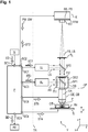
- the Figure 1 shows a microscope system or a device V, in which a sample area P is provided on a slide OT.
- the sample area P has a biological sample.
- the sample area P is held in a sample holder PH, which is preferably attached to a table TI which can be moved in the z direction or in its height.
- the table TI and the sample holder PH can be viewed as a combined unit or a combined sample holder PH, TI.
- the sample holder PH can be moved in a Z direction towards an objective OB along an optical axis OA of the objective.
- the objective OB can also be referred to as an optical unit OE.
- the sample holder PH, TI can be moved with respect to the objective OB.
- the objective OB can also be movable with respect to the sample holder PH, TI.
- the movability relates to the setting of a relative distance between the sample area P and the objective OB.
- the objective OB and the sample area P or the sample holder PH, TI can be moved relative to one another along the optical axis OA of the objective OB in order to change a relative distance between the objective OB and the sample area P.
- the sample area P has at least one interface.
- the Figure 2 shows the sample area 2, P in detail.
- the sample area 2 comprises a slide with an embedded biochip, as shown in greater detail in a schematic side sectional view in FIG Fig. 2 is illustrated.
- the sample area 2 comprises an object carrier 41 which has a plate-shaped structure with a recess 43.
- a biochip 45 is arranged in the recess 43 of the specimen slide 41 and attached to the specimen slide 41 by means of an adhesive 47.
- Glycerine 49 is filled around the biochip 45 within the recess 43.
- a (biological) sample 51 is applied to the biochip 45.
- the sample 51 is thus embedded in the glycerol 49.
- a cover glass 53 covers the recess 43 with the sample 51 located therein surrounded with glycerine 49.
- the coverslip 53 has an upper surface 55 which forms a first interface and a lower surface 57 which forms a second interface.
- the surface 59 of the biochip 45 forms a third interface. In particular, this will third interface 59 determined in a method for focusing according to an embodiment of the present invention.
- the preferred relative distance (relative vertical distance between the objective and the sample area) is assumed when the laser beam from the objective is focused on the surface 59 (that is to say the third interface) of the biochip 45.
- one or more images can be recorded by reading out the preferably entire detection area of the image sensor, in particular if the sample 51 is illuminated, for example, with fluorescence-stimulating light.
- the sample area can be a sample area extended in three dimensions, which is thus extended in two lateral directions and is extended in a depth direction perpendicular thereto.
- a (biological) sample can be located within the sample area at a certain depth, of which a focused image, in particular a fluorescent image, is to be recorded.
- the method (and the microscopy system) can thus be used in particular in autoimmune diagnostics for evaluating immunofluorescence preparations.
- the method and the microscopy system can support an indirect immunofluorescence test (IIFT). The method can ensure rapid processing of the samples to be found, which requires rapid focusing of the samples.
- IIFT indirect immunofluorescence test
- the at least one interface can be, for example, a planar interface, for example between a solid material and air, between a solid material and a liquid, or between a solid material and an (organic) sample.
- the presence of the at least one interface can facilitate focusing or increase the reliability of the focusing.
- the method is designed in such a way that at least one interface, in particular two interfaces, does not adjoin air, wherein the sample area comprises in particular an organic sample that lies on a biochip, is embedded in a liquid substance and from a Cover glass is covered, furthermore in particular the upper side of the cover glass forms a first interface, wherein the The underside of the cover glass forms a second interface, and the surface of the biochip forms a third interface.
- the organic sample can comprise, for example, a histological sample which is, for example, stained and / or has been mixed with one or more fluorescent markers or fluorescent molecules.
- the fluorescent markers or fluorescent molecules can be bound to predetermined locations or receptors or antigens on the organic sample.
- the liquid substance can comprise glycerin, for example.
- the organic sample can be, for example, a wet organic sample, it being possible for the sample to be prevented from drying out.
- Embodiments of the invention make it possible to image an organic sample embedded in a liquid (three-dimensionally, ie essentially from all sides).
- the interfaces can be characterized by a change in the refractive index above and below the interface. For example, at the transition at the interface between a liquid medium and a solid medium, the refractive index can change less than at a transition at an interface from air to a solid medium, for example glass.
- the degree of reflection at the interface can be lower, the lower the change in the refractive index at the interface. Despite a relatively low reflection at the third interface, this can be detected by the method according to the invention.
- the device V has a laser light source or laser source LL which generates a laser light or a laser beam LS.
- the laser beam LS is directed in the direction of the objective OB via a beam splitter SP2 and enters an optical opening OF the objective OB.
- the laser beam is, in particular, an essentially collimated, parallel bundle of rays.
- the beam splitter SP2 is in particular a beam splitter which reflects a first power component of an incident light and transmits a second power component of the incident light.
- Laser light which is reflected back at a boundary surface of the sample area P is then reflected by the objective OB through a dichroic beam splitter SP1 and an optical filter FI2 and the beam splitter SP2 to a lens or tube lens TL.
- the tube lens TL together with the objective causes an image of the laser beam on an image sensor BS, which is in particular a photosensor PS.
- a color filter matrix FFM is connected upstream of the image sensor BS.
- the image sensor BS and the color filter matrix FFM are preferably a component a camera K, which preferably has camera optics KO.
- the objective OB is designed in such a way that it projects laser beams, which enter parallel to one another as a parallel beam path or a collimated, parallel bundle of rays into its optical opening OF facing the laser light source LL, onto a point of a focal plane of the objective on the other side of the objective , wherein the point can be the focal point or a point offset from the focal point in the focal plane, if the beam does not run exactly parallel to the optical axis of the objective.
- Laser beams which are reflected from precisely this point, in particular the focal point, in the focal plane and from there back into the objective are in turn formed into a parallel beam path on the opening side or the optical side OF towards the image sensor BS.
- the objective OB If, for example, the laser beam LS is a collimated, parallel bundle of rays, the objective OB generates a projection of the laser beam in its entire intensity onto the one point, in particular the focal point, in the focal plane of the objective.
- the beam path captured by the objective from this point, in particular this focal point, which is bundled on the other side of the objective to form a parallel, collimated beam path, can then be directed to an imaging point by means of a lens TL, preferably a tube lens, connected downstream of the objective OB are projected on which the image sensor BS is arranged.
- the objective OB and the tube lens TL produce an image of the reflected laser beam on the image sensor BS.
- focal plane can also be referred to as the term focal length plane.
- a cross-sectional diameter of the laser beam LS is essentially the same as the entrance opening of the objective OB.
- the entry opening can also be referred to as an aperture.
- the objective OB can comprise one or more lenses which can be arranged one behind the other along the optical axis of the objective.
- the objective can, for example, provide a 10-fold, 20-fold or, for example, 40-fold magnification and, for example, have a numerical aperture of between 0.3 and 0.8.
- the diameter of the parallel, The collimated laser beam is preferably dimensioned so that the full aperture of the microscope objective is illuminated.
- the laser beam LS is a parallel, collimated beam path
- the laser beam is then projected through the objective OB onto one point of the focal plane, which point can be the focal point or a point offset from the focal point in the focal plane .
- the focal plane and the focal plane then coincide. If, by changing the relative distance, the boundary surface of the sample area is exactly at the focal plane, the laser beam projected onto the point of the focal plane is reflected back to the objective OB, the objective OB and the tube lens TL then mapping this reflection to a point on the image sensor Cause BS.
- the image sensor BS is again in the Figure 3A shown.
- the image sensor BS has different individual pixels P11,..., P14.
- the image sensor is a color filter matrix from the FFM Figure 3b upstream. Individual color filter elements or color channel elements P1 to P9 are also shown. A respective color channel is defined by a respective specific color choice, which in this exemplary embodiment is an RGB color filter matrix. Alternatively, a CMYK color filter matrix is conceivable.
- the pixel P11 of the image sensor BS from the Figure 3 for example, the matrix element P1 is connected upstream.
- the pixel element P14 of the Figure 3a for example, the color filter element P5 is connected upstream.
- a respective color filter element, in particular precisely one respective filter element, of the color filter matrix FFM is preferably connected to or assigned to a respective pixel element of the image sensor BS.
- Obtaining a color image by means of an image sensor BS from the Figure 3a with an upstream color filter matrix FFM from the Figure 3b can be done using a so-called de-bayering process.
- the device V also has an excitation light source AL for emitting excitation light AS.
- This excitation light AS is filtered once again, preferably by an optical filter Fl1, before it is directed by means of the dichroic beam splitter SP1 towards the objective OB and thus towards the sample area or onto the sample area.
- This excitation light is used to excite fluorescence in the sample area P.
- the excitation light source is preferably an LED, preferably a blue LED.
- Fluorescence radiation FS of the biological sample can then pass from the sample area P back through the objective OB through the beam splitter SP2 to an optical filter Fl2.
- the optical filter Fl2 preferably filters out light from the excitation radiation AS.
- the fluorescence radiation FS then passes through the beam splitter SP2 and arrives from there to the tube lens TL which, together with the objective OB, effects an image on the image sensor BS and the color filter matrix FM connected upstream of the sensor.
- the combination of the optical filter Fl1, the optical filter Fl2 and the dichroic beam splitter SP1 can also be referred to as an optical unit OE2.
- the objective OB is designed to direct the laser beam onto the sample area and to bring about a focusing of the laser beam in a focusing plane.
- the image sensor BS is designed to acquire a set of pixel intensity values which are brought about by the laser beam reflected at the boundary surface of the sample area P and transmitted back through the lens on corresponding sensor pixels of the image sensor, the laser beam not only passing through the lens OB but preferably also is imaged by the lens or tube lens TL on the image sensor BS.
- a lens TL in particular a tube lens
- a detection beam path between the objective OB and the detection surface, which lens images a focal plane of the objective onto the image sensor.
- a parallel beam path can be present behind the lens (or downstream of the lens) and the parallel beams can be imaged by the tube lens in an image-side focal plane.
- a displacement of the objective relative to the tube lens has no or no significant influence on the imaging of the parallel rays in the image-side focal plane of the tube lens.
- At a certain point within the sub-area of the detection area only rays from a certain, common point in the focal plane of the objective in different directions, in particular the focal point.
- scattered light which did not start from a point in the object-side focal plane of the objective in different directions
- the image sensor BS is a photosensor, in particular a CMOS sensor or a CCD sensor.
- the color filter matrix FFM is preferably a Bayer matrix.
- the color filter matrix FFM preferably has a plurality of color channels, in particular at least one green channel and one red channel, particularly preferably also a blue channel.
- the device V off Figure 1 has a processor P which can control the specimen holder PH, TI via an interface SC4 by means of a control signal ST4, so that the objective OB and the specimen area P have respective different relative distances from one another.
- the processor P is designed by means of an interface SC2 to send a control signal or a plurality of control signals SC2 to the camera K or the image sensor BS, so that the image sensor detects pixel intensity values PW or sensor values SW.
- the image sensor BS then provides these pixel intensity values PW or sensor values SW to the processor P via the interface SC2.
- the processor P uses the image sensor BS to record a respective set of pixel intensity values for a respective relative distance.
- the processor P can therefore move the sample holder PH, TI continuously or gradually and then record a respective image or a respective set of pixel intensity values for respective relative distances between objective OB and sample area P.
- a separate, respective set of pixel intensity values is therefore recorded as an image or preferably a partial image of the image sensor for a respective relative distance.
- the processor P determines a respective focus metric on the basis of the respective set of pixel intensity values or on the basis of the respective image for the respective relative distance.
- the relative distance between the sample area P and the objective B can preferably be set alternatively by the processor P in that the processor P has a Interface SC6 controls the objective OB by means of a control signal ST6 in such a way that the objective OB changes its relative distance along the optical axis OA of the objective OB with respect to the sample area P.
- the processor P can activate or deactivate this laser light source LL via a control signal ST7.
- the processor P can activate or deactivate the excitation light source AL via a control signal ST3.
- the processor P determines a preferred relative distance between the objective OB and the sample area P.
- the processor P then controls the objective OB and / or the sample holder PH in such a way that the preferred relative distance is set, that the excitation light source AL is also activated and that the microscopic fluorescence image is also captured as a color image by means of the image sensor BS.
- the acquisition of the microscopic fluorescence image as a color image is effected by the processor in that the processor P receives the pixel values PW or sensor values SW of the image sensor BS via the interface SC2 and generates a corresponding color image on the basis of these pixel values.
- the processor P does not have to be an integral part of the device V; it can be logically separated from the device, as in FIG Figure 1 indicated by a logical separation TR.
- the interfaces SC2, SC7, SC3, SC6, SC4 can be wholly or partially combined as one or more data interfaces, in particular wired or non-wired, i.e. wireless, in particular in the form of a local area network (LAN) interface .
- LAN local area network
- the processor P preferably has an interface SC1 to a network N.
- the network N is preferably a data network such as the Internet.
- the processor P can preferably receive an input signal ES from the network N, which indicates a request to the processor P to carry out the proposed method in order to bring about a focusing and to capture the fluorescent image as a color image.
- the processor P preferably has an interface SC5 to an output unit via which the processor can provide image data BD.
- the output unit AE can then be, for example, a monitor or a display, so that the image data BD can be, for example, digital image data according to the HTMI standard. Other image data standards are possible.
- the output unit AE can in turn be a network interface via which the processor uses the interface SC5 to transmit the image data BD in digital form to a network.
- the interface SC5 and the interface SC1 can also be in the form of an integral or the same interface.
- Figure 4e shows an overall image of a point laser reflection, as it was recorded from the entire surface of a gray value image sensor without an upstream color filter matrix for a wavelength of 650 nm.
- the entire image 63 comprises, for example, 1024 x 1024 pixels.
- the image sensor or the pixels is read out, while the relative distance between the objective OB and the sample area P is changed.
- Figures 4a, 4b and 4c illustrate by way of example partial areas 65a, 65b, 65c and the pixel intensity values or intensities detected by the pixels contained therein as gray values of an image of a reflected laser beam for different relative distances.
- the partial areas 65a, 65b, 65c can be formed by 16 ⁇ 16 pixels, for example.
- the pixel intensity values of the pixels of the sub-area 65a then correspond to a set of pixel intensity values for a relative distance. The same applies to the areas 65b and 65c for other relative distances.
- the respective highest intensity value Gmax is also illustrated. If the focal plane of the objective is moved away from the corresponding interface in the slide (see Figures 4a, 4c ), the laser signal is depicted attenuated or broadened. the end Figures 4a, 4b and 4c it becomes clear that the modulation of the individual pixels already decreases significantly with shifts of approx.
- the highest pixel intensity value in each case is used as the focus metric, there are further advantages: In the case of a pattern projection, it would not be sufficient to consider only a single highest pixel intensity of the sub-area as a measure for focusing, but several pixels would have to be combined and analyzed together of the multiple pixels, a focusing based on the flat pattern would have to be determined as a measure for a focusing, which would clearly be more time-consuming than considering the highest or maximum pixel intensity of the image sensor or a sub-area thereof.
- Figure 4d illustrates an example of a preferably used predetermined area or a sub-area 66 in which intensity values are recorded and evaluated in order to preferably determine a highest or maximum pixel intensity value for this area (65a, 65b, 65c).
- the highest pixel gray value or the highest intensity value can thus preferably be determined for each partial image recorded for a specific relative distance.
- the processor P can link the camera data or intensity values with the associated relative distances and also determine the preferred relative distance.
- the resulting exemplary pixel intensity values show in the case that a laser wavelength of 635 nm is used when using an image sensor with an upstream color filter matrix.
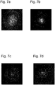
- a resulting intensity distribution over the pixel area is shown for the case of a slight defocusing. It is clear that there is not an expected intensity for all pixels, but that certain pixels are virtually masked out, as these pixels are located behind color filter elements that are not assigned to a red channel and thus do not adequately transmit light with a wavelength of 635 nm.
- the Figure 7d When using an image sensor with an upstream color filter matrix, shows the resulting pixel intensity values for the case of focusing.
- the Figure 4b there is no clear point with a high intensity of the reflected laser beam to be seen here, but also here in the Figure 7b individual pixels are virtually hidden.
- Such a fading out of certain pixels in the course of a detection of resulting pixel intensity values as a representation of one of the reflected laser beams can have a negative effect on focus metrics to be determined.
- the resulting pixel intensity values of the Figures 7c and 7d are subject to artifacts which are caused by the different transmissivities of the different color channels of the color filter matrix. These artifacts have an influence on the focus metrics to be determined, so that a determination result of the preferred relative distance can be made more difficult or falsified. The final result can then be that there is insufficient focus for the acquisition of the fluorescence image.
- An exemplary focus metric can be a highest or maximum pixel intensity value within a sub-area, as shown in FIG Figure 7c or 7d is shown.
- Alternative focus metrics mentioned here can, for example, be based on one or more of the following operators based: weighted mean value of the pixel intensities in the selected image area, evaluation of the half-width of the pixel intensities, evaluation of the maximum or mean value of the edge image of the pixel intensities.
- An edge image can in particular be obtained by means of one of the operators Prewitt operator, Sobel operator, Laplacian-of-Gaussian / Marr-Hildreth operator or Difference-of-Gaussian. Such operators are particularly susceptible or sensitive to artifacts such as those in the Figures 7c and 7d you can see.
- the Figure 7a and the Figure 7b show the resulting pixel intensity values in the event that when using an image sensor and a color filter matrix Figure 1 in addition, a laser in the near-infrared range is used, in particular at 850 nm Figure 7a an expected distribution of a pixel intensity, as previously in Figure 4a shown.
- a focus metric can now be determined robustly and reliably here.
- the solution according to the invention using the image sensor and the upstream color filter matrix makes it possible, due to the choice of the wavelength of the laser beam in the near infrared range, to obtain respective images or respective amounts of pixel intensity values at the respective relative distances, as they are in the Figures 7a and 7b are shown and then precisely and reliably to determine respective focus metrics for respective relative distances on the basis of the respective images or respective quantities of pixel intensity values.
- the laser beam LS strikes the color filter matrix FFM in such a way that, for different relative distances, the laser beam each has different partial areas P1, .., P9 then hits, depending on the respective relative distance which is set between objective OB and sample area P, is transmitted to different degrees through the different subareas P1, ..., P9 of the color filter matrix FFM.
- an image sensor BS with an upstream color filter matrix FFM can still be used, since the laser is selected with a wavelength in the near-infrared range.
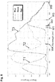
- the Figure 8 shows transmissivities T1, T2, T3 for respective color channels for an exemplary color filter matrix.
- the transmissivity T1 shows a blue channel
- the transmissivity T2 shows a green channel
- the transmissivity T3 shows a red channel.
- the image sensor with color filter matrix used here is preferably a SONY IMX250 sensor.
- a wavelength WA of 650 nm is shown.
- this wavelength WA there are color filter elements such as the element P8 from FIG Figure 3b not transmissive enough, so that when using an image sensor BS with the upstream color filter matrix FFM at this wavelength WA of the laser, a separate image sensor would have to be used in a separate red channel.
- the wavelength of the laser is used in a range from the wavelength W1 of 780 nm, preferably from the wavelength range W2 of 800 nm up to the wavelength W3 of 1000 nm.
- the transmissivity of color filter elements in the respective color channels is high enough so that by means of a scaling of the pixel intensity values or a scaling of the individual Let color channel information determine images of reflected laser beams, as in the Figures 7a and 7b shown.
- the use of the wavelength of 850 nm in the wavelength W3 is particularly advantageous Figure 8 , since scaling of individual color channel information can possibly be omitted here, since the transmissivity differences of the individual color channels are sufficiently small.
- the acquisition of a respective set of pixel intensity values for a respective relative distance takes place preferably by means of acquiring respective subsets of pixel intensity values for respective color channels, the respective set of pixel intensity values being determined on the basis of the subsets.
- the image sensor preferably provides a respective subset of pixels or a respective subset of pixel intensity values for each color channel, with its two-dimensional spatial position also being specified for each pixel or each pixel intensity value.
- the processor can take off Figure 1 then determine or assemble the set of pixel intensity values from the subsets.
- the processor in particular by means of a memory unit, can provide a corresponding scaling factor for a respective color channel, so that pixel intensity values of a subset of a specific color channel are first multiplied by the specific scaling factor assigned to the color channel, before the processor then the set of pixel intensity values from the subsets determine or put together. Pixel intensity values of a respective subset are therefore weighted with a predetermined scaling factor which depends on the type of color channel to which the respective subset of pixel intensity values belongs. In this way, differences in transmissivity of the individual color channels of the color filter matrix can be compensated for at the wavelength of the laser.
- the highest intensity value from a partial area of the image sensor can preferably be used as the focus metric.
- the highest intensity value within the sub-area can be set in a preferred manner in order to obtain a focus metric or a measure for the focusing of the sample area.
- no further processing or filtering of the sometimes many pixel intensity values of the image sensor or a sub-area of the image sensor is required Instead, it only has to be determined which is the highest intensity value corresponding to the corresponding relative distance within the image sensor or the sub-area under consideration. In this case, it is not important which pixel has detected the maximum value of the intensity values, so that the method is particularly fast.
- the laser beam is not reflected at a single point, which was previously the point in the focal plane and in particular the focal point, but the reflection occurs in a flat area of the sample area or the interface.
- the optical intensity of the laser beam is then distributed over a larger area of the partial area than is the case when the laser beam is only reflected in the single point of the focal plane. Therefore, intensity values then also result within the sub-area on the image sensor, which in total still represent or can represent the entire optical intensity of the laser beam, but the now highest intensity value is also lower than the highest intensity value in the configuration in which the laser beam is reflected by means of the interface precisely in one point of the focal plane.
- a precise filtering out of a reflected pattern e.g. by means of a diaphragm, does not have to be taken into account particularly high spatial resolution.
- a third interface for example, can then be detected by means of the course of the highest intensity values in order to determine a preferred relative distance.
- the sensitivity of the method can thus be increased and an extension of the imaged laser beam in the depth direction can essentially be equivalent to a depth of field of the optics.
- Fig. 5 illustrates an example of a curve 67 of the highest pixel intensity values determined (for each relative distance) as a function of the relative distance as a curve 67 in a coordinate system, with the relative distance (Z position) on an abscissa 69 and the highest on the ordinate 71 Pixel intensity value is plotted in the sub-area at the associated relative distance.
- the lowest Z value here indicates a position at which the sample area is furthest away from the objective
- the highest Z value indicates a position at which the sample area is closest to the objective.
- the objective and the sample area are first moved relative to one another by reducing a relative distance between the objective and the sample area starting from a largest distance to a smallest distance with a first distance resolution, the course of the highest pixel intensity values being determined, which is several Has maxima.
- the course has in particular a first local maximum 73, then a second local maximum 75 and finally a third local maximum 77 of the course.
- the curve 67 shows a characteristic signal pattern ("autofocus signal"), which the geometry of the sample area, as shown in FIG Fig. 2 is illustrated, is based. Since the structure of the sample region 2 is known, the Z position of the biochip 45, in particular the surface 59 of the biochip 45, can be determined from the signal profile 67.
- the curve 67 (autofocus signal) has a first maximum 73, which originates from the reflection of the laser beam 19 at the first interface 55 (upper surface of the cover glass 53). Furthermore, the curve 67 has a second maximum 75, which originates from the reflection of the laser beam 19 from the lower surface 57 (second interface) of the cover glass 53. Finally, the curve 67 has a third maximum 77, which originates from the reflection of the laser beam 19 from the surface 59 of the biochip 45 (third interface). The focus position of the biochip surface 59 or the relative distance results from the determination of the Z position 79 of the third signal maximum 77.
- the objective 3 can then be moved back again in the direction of the determined focus location or the preferred relative distance, increasing the distance between the objective and the sample area.
- the preferred relative distance is then in particular a temporarily preferred relative distance. This takes place in particular using a second distance resolution which is higher or finer than the first distance resolution.
- the length of the journey is controlled via the autofocus signal in such a way that it is monitored and evaluated simultaneously with the movement in Z. In this case, further highest pixel intensity values are determined at respective further relative distances as well a detection of the presence of the maximum 82 from the Figure 6 based on the other highest pixel intensity values.
- the final relative distance is then set to such a final position at which this is based on the other local maximum detected at the highest pixel intensity values is or was present.
- Fig. 6 illustrates this an autofocusing signal, which originates from the reflection of the laser beam 19 from the surface 59 of the biochip 45, that is, a third maximum 82 in a course at a position 85.
- the axial resolution of this signal 81 can be determined, for example, from the half-width ⁇ to be approximately 2.1 ⁇ m.
- the final preferred relative distance 85 can be determined, for example, as the Z position at which the maximum 82 occurs or as a center of gravity of the curve 81 or center of gravity of the maximum 82.
- the objective can then be relative to the sample area at the final preferred relative distance 85 at which the maximum 82 of the further highest intensity values was present.
- the surface of the biochip does not have to represent the optimal imaging plane for fluorescence microscopy, since the layer thickness of the sample 51 can in part be greater than the depth of field of the microscopy system. Therefore, several fluorescence recordings can be made around the determined focus position or the determined final preferred relative distance. Therefore, preferably based on the At the final preferred relative distance, multiple images of the sample area are captured by means of the image sensor. In this case, the relative distance between the objective and the sample area is changed along the optical axis at respective relative distances above and / or below the final preferred relative distance. In addition, the respective images are recorded at the respective relative distances by means of the image sensor. The processor then stores the respective images and determines respective focus metrics for the respective images. The processor then selects the image that has the best focus metric. The processor preferably discards the other images which do not have the best focus metric.
- the maxima have signal levels of a specific pattern.
- the third maximum 77 can preferably be recognized as reliably detected, for example, from the curve if the signal level of the local maximum 77 is greater than a previously determined or predetermined threshold value and if, furthermore, a local maximum is actually in fact is present, that is, intensity values to the right and left of the preferred relative distance 79 are less than the intensity precisely at the preferred relative distance.
- the preferred relative distance at which the laser beam is focused on the surface of the biochip can thus be determined in a reliable manner.
- the resolution of the autofocus system is approximately equal to the depth of field of the microscopy system.
- the evaluation of a maximum pixel intensity or the highest pixel intensity can result in a high spatial resolution of the focusing method in the Z direction.
- the method is designed in such a way that a relative distance between the objective and the sample area is initially reduced starting from a greatest distance, while intensity values of the pixels of the sub-area are recorded, so that in particular initially a first local maximum from the reflection of the laser beam originating from the first interface, then a second local maximum originating from the reflection of the laser beam from the second interface and finally a third local maximum originating from the reflection of the laser beam from the third interface can be detected.
- the first local maximum can be a global maximum of the course of the maxima as a function of the relative distance. Will all three (local) If maxima are detected in the course of the maxima as a function of the relative distance, the reliability of the focusing can be improved.
- a (local) maximum can be determined, for example, when a specific threshold value for the intensity of the pixel is exceeded.
- the threshold value can, for example, be derived from the previously detected (local) maximum.
- the first local maximum can be greater than the second local maximum and the second local maximum can in turn be greater than or essentially of the same height as the third local maximum. If this sequence of maxima is detected, the reliability of the identification of the interfaces, and thus the determination of the focus, can be increased.
- the preferred relative distance is then determined on the basis of the third maximum.
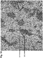
- the Figure 9 shows an exemplary fluorescence image of a tissue as a gray value image, the intensities of the gray value image being based on intensities from several color channels, in particular a green channel, a red channel and a blue channel. Shown is a fluorescence image of a rat kidney after incubation with a patient's serum and a secondary antibody which is labeled with a fluorescent dye.
- Such a glow can be brought about on the one hand by the excitation of a fluorescent dye bound in the tissue.
- there can also be so-called autofluorescence of the tissue in a brown or orange area, that is to say with a red component, which is independent of a binding of fluorescent dyes of the secondary antibody in the tissue.
- a region of a tissue can also shine in that light from the excitation light source is reflected by the tissue.
- the Figure 11 shows pure green channel information of the same image from the Figures 9 and 10 . It can be clearly seen that the structure SK1 shines more strongly in a green channel or with a green component than is the case for the structure SK2.
- the Figure 12 shows pure red channel information of the same image from the Figures 9 and 10 . It can be seen here that both the structure SK1 and the structure SK2 light up in the red channel or with a red component to approximately the same extent.
- the method according to the invention and the device according to the invention are therefore particularly advantageous, since the fluorescence image can be captured as a digital color image with green and red components by means of the one image sensor and the color filter matrix, but at the same time a reflection can also be performed without the use of a further image sensor of the laser beam can be detected by means of the same image sensor with an upstream color filter matrix in order to bring about focusing, since the laser has a wavelength in the near-infrared range.
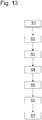
- FIG. 3 shows a flow diagram of steps which the processor according to FIG preferred embodiment performs.
- a step S1 the processor provides the control signal ST7 for activating a laser light source.
- the processor provides the control signal ST4 and / or ST6 for controlling the objective and / or the specimen holder, so that the objective and the specimen holder have different relative distances from one another.
- the processor detects a respective set of pixel intensity values for respective relative distances by the processor receiving a respective set of pixel intensity values from the image sensor with the upstream color filter matrix for a respective relative distance.
- a respective set of pixel intensity values is detected by detecting respective subsets of pixel intensity values of respective color channels for the corresponding relative distance.
- the processor receives respective subsets of pixel intensity values of respective color channels from the image sensor.
- the processor determines the respective set of pixel intensity values on the basis of the respective subsets of the respective color channels by means of color channel-dependent scaling of the pixel intensity values and by combining the set of pixel intensity values from the scaled, respective subsets of pixel intensity values.
- a step S4 the processor determines a respective focus metric for a respective relative distance on the basis of the respective set of pixel intensity values detected or determined for the respective relative distance.
- step S5 the processor sets the preferred relative distance via the control signal ST4 and / or the control signal ST6.
- step S6 the processor activates the excitation light source by means of the control signal ST3.
- the processor receives pixel intensity values from the image sensor and thus determines or captures the microscopic fluorescence image by means of the image sensor (BS),
- exemplary embodiments of the invention can implement the processor in hardware and / or in software.
- the processor mentioned here can be implemented here as at least one unit or by several units in a network.
- the implementation can be carried out using a digital storage medium such as a floppy disk, a DVD, a Blu-Ray disk, a CD, a ROM, a PROM, an EPROM, an EEPROM or a FLASH memory, a hard disk or other magnetic memory or optical memory are carried out on the electronically readable control signals are stored, which can interact with a programmable hardware component or cooperate in such a way that the respective method is carried out.
- the digital storage medium can therefore be machine-readable or computer-readable.
- Some exemplary embodiments thus include a data carrier which has electronically readable control signals which are capable of interacting with a programmable computer system or a programmable hardware component in such a way that one of the methods described herein is carried out.
- exemplary embodiments or parts of the exemplary embodiments of the present invention can be implemented as a program, firmware, computer program or computer program product with a program code or as data, the program code or the data being effective to carry out one of the methods or a part of a method if the program runs on a processor or a programmable hardware component.
Landscapes
- Physics & Mathematics (AREA)
- Chemical & Material Sciences (AREA)
- Analytical Chemistry (AREA)
- General Physics & Mathematics (AREA)
- Engineering & Computer Science (AREA)
- Optics & Photonics (AREA)
- Multimedia (AREA)
- Health & Medical Sciences (AREA)
- Signal Processing (AREA)
- Life Sciences & Earth Sciences (AREA)
- Nuclear Medicine, Radiotherapy & Molecular Imaging (AREA)
- Biochemistry (AREA)
- General Health & Medical Sciences (AREA)
- Immunology (AREA)
- Pathology (AREA)
- Computer Vision & Pattern Recognition (AREA)
- Biomedical Technology (AREA)
- Molecular Biology (AREA)
- Microscoopes, Condenser (AREA)
- Investigating, Analyzing Materials By Fluorescence Or Luminescence (AREA)
Priority Applications (6)
| Application Number | Priority Date | Filing Date | Title |
|---|---|---|---|
| EP18214781.9A EP3671309B1 (de) | 2018-12-20 | 2018-12-20 | Verfahren und mikroskopiersystem zum aufnehmen eines mikroskopischen fluoreszenzbildes eines probenbereiches mit einer biologischen probe |
| ES18214781T ES2912473T3 (es) | 2018-12-20 | 2018-12-20 | Procedimiento y sistema de microscopía para obtener una imagen de fluorescencia microscópica de un área para la muestra con una muestra biológica |
| PL18214781T PL3671309T3 (pl) | 2018-12-20 | 2018-12-20 | Sposób i układ mikroskopowy do rejestrowania mikroskopowego obrazu fluorescencyjnego obszaru próbki z próbkę biologiczną |
| BR102019026948-0A BR102019026948B1 (pt) | 2018-12-20 | 2019-12-17 | Processo e sistema de microscopia para tomada de uma imagem fluorescente microscópica de uma região de amostra com uma amostra biológica |
| US16/718,503 US11199500B2 (en) | 2018-12-20 | 2019-12-18 | Method and microscopy system for recording a microscopic fluorescence image of a sample region containing a biological sample |
| CN201911321405.4A CN111352228B (zh) | 2018-12-20 | 2019-12-20 | 用于拍摄试样区域的荧光图像的方法和显微镜系统 |
Applications Claiming Priority (1)
| Application Number | Priority Date | Filing Date | Title |
|---|---|---|---|
| EP18214781.9A EP3671309B1 (de) | 2018-12-20 | 2018-12-20 | Verfahren und mikroskopiersystem zum aufnehmen eines mikroskopischen fluoreszenzbildes eines probenbereiches mit einer biologischen probe |
Publications (2)
| Publication Number | Publication Date |
|---|---|
| EP3671309A1 EP3671309A1 (de) | 2020-06-24 |
| EP3671309B1 true EP3671309B1 (de) | 2021-11-10 |
Family
ID=64755244
Family Applications (1)
| Application Number | Title | Priority Date | Filing Date |
|---|---|---|---|
| EP18214781.9A Active EP3671309B1 (de) | 2018-12-20 | 2018-12-20 | Verfahren und mikroskopiersystem zum aufnehmen eines mikroskopischen fluoreszenzbildes eines probenbereiches mit einer biologischen probe |
Country Status (6)
| Country | Link |
|---|---|
| US (1) | US11199500B2 (pl) |
| EP (1) | EP3671309B1 (pl) |
| CN (1) | CN111352228B (pl) |
| BR (1) | BR102019026948B1 (pl) |
| ES (1) | ES2912473T3 (pl) |
| PL (1) | PL3671309T3 (pl) |
Families Citing this family (5)
| Publication number | Priority date | Publication date | Assignee | Title |
|---|---|---|---|---|
| EP3418789A1 (de) * | 2017-06-20 | 2018-12-26 | Euroimmun Medizinische Labordiagnostika AG | Verfahren und mikroskopiesystem zum aufnehmen eines bildes |
| ES2903440T3 (es) * | 2018-09-13 | 2022-04-01 | Euroimmun Medizinische Labordiagnostika Ag | Procedimiento y dispositivo para registrar y visualizar una imagen de inmunofluorescencia de una muestra biológica |
| EP4198604B1 (en) * | 2021-12-17 | 2025-10-29 | Thermo Electron Scientific Instruments LLC | Method and system for positioning a sample |
| CN114544004A (zh) * | 2022-02-25 | 2022-05-27 | 浙江天铂云科光电股份有限公司 | 一种用于红外热像仪的自动聚焦方法 |
| EP4625019A1 (de) | 2024-03-26 | 2025-10-01 | Euroimmun Medizinische Labordiagnostika AG | Verfahren zur bestimmung eines fokussierungsmasses eines mikroskopbildes |
Family Cites Families (9)
| Publication number | Priority date | Publication date | Assignee | Title |
|---|---|---|---|---|
| JP4971816B2 (ja) * | 2007-02-05 | 2012-07-11 | 三洋電機株式会社 | 撮像装置 |
| DE102008015885A1 (de) | 2008-03-26 | 2009-10-01 | Synentec Gmbh | Vorrichtung und Verfahren zur Autofokussierung von optischen Geräten, insbesondere von Mikroskopen |
| KR101172745B1 (ko) * | 2010-01-29 | 2012-08-14 | 한국전기연구원 | 생체로부터 발생하는 다중 분광 광 영상 검출 및 광치료를 위한 복합 장치 |
| US9407838B2 (en) | 2013-04-23 | 2016-08-02 | Cedars-Sinai Medical Center | Systems and methods for recording simultaneously visible light image and infrared light image from fluorophores |
| WO2016022359A1 (en) * | 2014-08-06 | 2016-02-11 | Cellomics, Inc. | Image-based laser autofocus system |
| CN204392456U (zh) * | 2015-02-12 | 2015-06-10 | 张李静 | 色彩滤镜阵列 |
| JP6783778B2 (ja) | 2015-02-18 | 2020-11-11 | アボット ラボラトリーズ | 顕微鏡を基体上に自動的に合焦するための方法、システム、及び装置 |
| JP2017079904A (ja) | 2015-10-26 | 2017-05-18 | ソニー株式会社 | 手術顕微鏡、画像処理装置、及び、画像処理方法 |
| JP6259156B1 (ja) * | 2017-10-03 | 2018-01-10 | 日本板硝子株式会社 | 光学フィルタ及び撮像装置 |
-
2018
- 2018-12-20 EP EP18214781.9A patent/EP3671309B1/de active Active
- 2018-12-20 ES ES18214781T patent/ES2912473T3/es active Active
- 2018-12-20 PL PL18214781T patent/PL3671309T3/pl unknown
-
2019
- 2019-12-17 BR BR102019026948-0A patent/BR102019026948B1/pt active IP Right Grant
- 2019-12-18 US US16/718,503 patent/US11199500B2/en active Active
- 2019-12-20 CN CN201911321405.4A patent/CN111352228B/zh active Active
Also Published As
| Publication number | Publication date |
|---|---|
| US11199500B2 (en) | 2021-12-14 |
| ES2912473T3 (es) | 2022-05-25 |
| CN111352228B (zh) | 2023-07-28 |
| PL3671309T3 (pl) | 2022-03-28 |
| CN111352228A (zh) | 2020-06-30 |
| BR102019026948A2 (pt) | 2021-02-23 |
| BR102019026948B1 (pt) | 2022-04-26 |
| EP3671309A1 (de) | 2020-06-24 |
| US20200200682A1 (en) | 2020-06-25 |
Similar Documents
| Publication | Publication Date | Title |
|---|---|---|
| EP3671309B1 (de) | Verfahren und mikroskopiersystem zum aufnehmen eines mikroskopischen fluoreszenzbildes eines probenbereiches mit einer biologischen probe | |
| EP3642660B1 (de) | Verfahren und mikroskopiesystem zum aufnehmen eines bildes | |
| EP2030062B1 (de) | Autofokuseinrichtung für die mikroskopie | |
| EP2193398B1 (de) | Verfahren zur mikroskopischen dreidimensionalen abbildung einer probe | |
| EP2641078B1 (de) | Tiefenauflösungsgesteigerte mikroskopie | |
| EP3721279B1 (de) | Mikroskopsystem und verfahren zur mikroskopischen abbildung mit einem solchen mikroskopsystem | |
| EP2444833B1 (de) | SPIM-Mikroskop mit sequenziellem Lightsheet | |
| DE19653413C2 (de) | Rastermikroskop, bei dem eine Probe in mehreren Probenpunkten gleichzeitig optisch angeregt wird | |
| EP2803977B1 (de) | Verfahren zur 3D-hochauflösenden Lokalisierungsmikroskopie | |
| DE60037184T2 (de) | Abbildungssystem für optischen bildabtaster | |
| DE69806496T2 (de) | Gerät und verfahren zur mikroskopie unter verwendung räumlich modulierten lichtes | |
| EP1907826B2 (de) | Auflösungsgesteigerte lumineszenz-mikroskopie | |
| DE102007055530A1 (de) | Laserstrahlbearbeitung | |
| EP2406679A1 (de) | Autofokusverfahren und autofokuseinrichtung | |
| WO2009124700A1 (de) | Vorrichtung für mikroskopie mit selektiver beleuchtung einer ebene | |
| EP3992687B1 (de) | Mikroskop und verfahren zur lichtfeldmikroskopie mit lichtblattanregung sowie zur konfokalen mikroskopie | |
| EP2803978B1 (de) | Verfahren zur 3D-hochauflösenden Lokalisierungsmikroskopie | |
| DE10121064A1 (de) | Vorrichtung und Verfahren zur optischen Messung von chemischen und/oder biologischen Proben | |
| EP2647982B1 (de) | Verfahren und vorrichtung zum bestimmen eines kritischen winkels eines anregungslichtstrahls | |
| DE102011055426B4 (de) | Mikroskopieverfahren zur Erkennung biologischer Zielobjekte | |
| DE102013105102A1 (de) | Verfahren und Vorrichtung zur Bestimmung von Merkmalen an Messobjekten | |
| DE19957418B4 (de) | Verfahren zur lichtoptischen Abtastung eines Objekts und Rastermikroskop zur Anwendung des Verfahrens | |
| DE10317669B4 (de) | Verfahren zur Separierung von Detektionskanälen eines mikroskopischen Systems | |
| WO2000068667A1 (de) | Mikroskopsysteme zur optischen abtastung von mikroskopischen objekten | |
| DE102015222768B4 (de) | Vorrichtung zur simultanen Fluoreszenz-Kontrastgebung in Durchlicht und Auflicht |
Legal Events
| Date | Code | Title | Description |
|---|---|---|---|
| PUAI | Public reference made under article 153(3) epc to a published international application that has entered the european phase |
Free format text: ORIGINAL CODE: 0009012 |
|
| STAA | Information on the status of an ep patent application or granted ep patent |
Free format text: STATUS: THE APPLICATION HAS BEEN PUBLISHED |
|
| AK | Designated contracting states |
Kind code of ref document: A1 Designated state(s): AL AT BE BG CH CY CZ DE DK EE ES FI FR GB GR HR HU IE IS IT LI LT LU LV MC MK MT NL NO PL PT RO RS SE SI SK SM TR |
|
| AX | Request for extension of the european patent |
Extension state: BA ME |
|
| STAA | Information on the status of an ep patent application or granted ep patent |
Free format text: STATUS: REQUEST FOR EXAMINATION WAS MADE |
|
| 17P | Request for examination filed |
Effective date: 20201222 |
|
| RBV | Designated contracting states (corrected) |
Designated state(s): AL AT BE BG CH CY CZ DE DK EE ES FI FR GB GR HR HU IE IS IT LI LT LU LV MC MK MT NL NO PL PT RO RS SE SI SK SM TR |
|
| GRAP | Despatch of communication of intention to grant a patent |
Free format text: ORIGINAL CODE: EPIDOSNIGR1 |
|
| STAA | Information on the status of an ep patent application or granted ep patent |
Free format text: STATUS: GRANT OF PATENT IS INTENDED |
|
| INTG | Intention to grant announced |
Effective date: 20210611 |
|
| GRAS | Grant fee paid |
Free format text: ORIGINAL CODE: EPIDOSNIGR3 |
|
| GRAA | (expected) grant |
Free format text: ORIGINAL CODE: 0009210 |
|
| STAA | Information on the status of an ep patent application or granted ep patent |
Free format text: STATUS: THE PATENT HAS BEEN GRANTED |
|
| AK | Designated contracting states |
Kind code of ref document: B1 Designated state(s): AL AT BE BG CH CY CZ DE DK EE ES FI FR GB GR HR HU IE IS IT LI LT LU LV MC MK MT NL NO PL PT RO RS SE SI SK SM TR |
|
| REG | Reference to a national code |
Ref country code: GB Ref legal event code: FG4D Free format text: NOT ENGLISH |
|
| REG | Reference to a national code |
Ref country code: AT Ref legal event code: REF Ref document number: 1446604 Country of ref document: AT Kind code of ref document: T Effective date: 20211115 Ref country code: CH Ref legal event code: EP |
|
| REG | Reference to a national code |
Ref country code: DE Ref legal event code: R096 Ref document number: 502018007757 Country of ref document: DE |
|
| REG | Reference to a national code |
Ref country code: IE Ref legal event code: FG4D Free format text: LANGUAGE OF EP DOCUMENT: GERMAN |
|
| REG | Reference to a national code |
Ref country code: LT Ref legal event code: MG9D |
|
| REG | Reference to a national code |
Ref country code: NL Ref legal event code: MP Effective date: 20211110 |
|
| PG25 | Lapsed in a contracting state [announced via postgrant information from national office to epo] |
Ref country code: RS Free format text: LAPSE BECAUSE OF FAILURE TO SUBMIT A TRANSLATION OF THE DESCRIPTION OR TO PAY THE FEE WITHIN THE PRESCRIBED TIME-LIMIT Effective date: 20211110 Ref country code: LT Free format text: LAPSE BECAUSE OF FAILURE TO SUBMIT A TRANSLATION OF THE DESCRIPTION OR TO PAY THE FEE WITHIN THE PRESCRIBED TIME-LIMIT Effective date: 20211110 Ref country code: FI Free format text: LAPSE BECAUSE OF FAILURE TO SUBMIT A TRANSLATION OF THE DESCRIPTION OR TO PAY THE FEE WITHIN THE PRESCRIBED TIME-LIMIT Effective date: 20211110 Ref country code: BG Free format text: LAPSE BECAUSE OF FAILURE TO SUBMIT A TRANSLATION OF THE DESCRIPTION OR TO PAY THE FEE WITHIN THE PRESCRIBED TIME-LIMIT Effective date: 20220210 |
|
| REG | Reference to a national code |
Ref country code: ES Ref legal event code: FG2A Ref document number: 2912473 Country of ref document: ES Kind code of ref document: T3 Effective date: 20220525 |
|
| PG25 | Lapsed in a contracting state [announced via postgrant information from national office to epo] |
Ref country code: IS Free format text: LAPSE BECAUSE OF FAILURE TO SUBMIT A TRANSLATION OF THE DESCRIPTION OR TO PAY THE FEE WITHIN THE PRESCRIBED TIME-LIMIT Effective date: 20220310 Ref country code: SE Free format text: LAPSE BECAUSE OF FAILURE TO SUBMIT A TRANSLATION OF THE DESCRIPTION OR TO PAY THE FEE WITHIN THE PRESCRIBED TIME-LIMIT Effective date: 20211110 Ref country code: PT Free format text: LAPSE BECAUSE OF FAILURE TO SUBMIT A TRANSLATION OF THE DESCRIPTION OR TO PAY THE FEE WITHIN THE PRESCRIBED TIME-LIMIT Effective date: 20220310 Ref country code: NO Free format text: LAPSE BECAUSE OF FAILURE TO SUBMIT A TRANSLATION OF THE DESCRIPTION OR TO PAY THE FEE WITHIN THE PRESCRIBED TIME-LIMIT Effective date: 20220210 Ref country code: NL Free format text: LAPSE BECAUSE OF FAILURE TO SUBMIT A TRANSLATION OF THE DESCRIPTION OR TO PAY THE FEE WITHIN THE PRESCRIBED TIME-LIMIT Effective date: 20211110 Ref country code: LV Free format text: LAPSE BECAUSE OF FAILURE TO SUBMIT A TRANSLATION OF THE DESCRIPTION OR TO PAY THE FEE WITHIN THE PRESCRIBED TIME-LIMIT Effective date: 20211110 Ref country code: HR Free format text: LAPSE BECAUSE OF FAILURE TO SUBMIT A TRANSLATION OF THE DESCRIPTION OR TO PAY THE FEE WITHIN THE PRESCRIBED TIME-LIMIT Effective date: 20211110 Ref country code: GR Free format text: LAPSE BECAUSE OF FAILURE TO SUBMIT A TRANSLATION OF THE DESCRIPTION OR TO PAY THE FEE WITHIN THE PRESCRIBED TIME-LIMIT Effective date: 20220211 |
|
| PG25 | Lapsed in a contracting state [announced via postgrant information from national office to epo] |
Ref country code: SM Free format text: LAPSE BECAUSE OF FAILURE TO SUBMIT A TRANSLATION OF THE DESCRIPTION OR TO PAY THE FEE WITHIN THE PRESCRIBED TIME-LIMIT Effective date: 20211110 Ref country code: SK Free format text: LAPSE BECAUSE OF FAILURE TO SUBMIT A TRANSLATION OF THE DESCRIPTION OR TO PAY THE FEE WITHIN THE PRESCRIBED TIME-LIMIT Effective date: 20211110 Ref country code: RO Free format text: LAPSE BECAUSE OF FAILURE TO SUBMIT A TRANSLATION OF THE DESCRIPTION OR TO PAY THE FEE WITHIN THE PRESCRIBED TIME-LIMIT Effective date: 20211110 Ref country code: EE Free format text: LAPSE BECAUSE OF FAILURE TO SUBMIT A TRANSLATION OF THE DESCRIPTION OR TO PAY THE FEE WITHIN THE PRESCRIBED TIME-LIMIT Effective date: 20211110 Ref country code: DK Free format text: LAPSE BECAUSE OF FAILURE TO SUBMIT A TRANSLATION OF THE DESCRIPTION OR TO PAY THE FEE WITHIN THE PRESCRIBED TIME-LIMIT Effective date: 20211110 Ref country code: CZ Free format text: LAPSE BECAUSE OF FAILURE TO SUBMIT A TRANSLATION OF THE DESCRIPTION OR TO PAY THE FEE WITHIN THE PRESCRIBED TIME-LIMIT Effective date: 20211110 |
|
| REG | Reference to a national code |
Ref country code: CH Ref legal event code: PL |
|
| REG | Reference to a national code |
Ref country code: DE Ref legal event code: R097 Ref document number: 502018007757 Country of ref document: DE |
|
| PG25 | Lapsed in a contracting state [announced via postgrant information from national office to epo] |
Ref country code: MC Free format text: LAPSE BECAUSE OF FAILURE TO SUBMIT A TRANSLATION OF THE DESCRIPTION OR TO PAY THE FEE WITHIN THE PRESCRIBED TIME-LIMIT Effective date: 20211110 |
|
| PLBE | No opposition filed within time limit |
Free format text: ORIGINAL CODE: 0009261 |
|
| STAA | Information on the status of an ep patent application or granted ep patent |
Free format text: STATUS: NO OPPOSITION FILED WITHIN TIME LIMIT |
|
| REG | Reference to a national code |
Ref country code: BE Ref legal event code: MM Effective date: 20211231 |
|
| 26N | No opposition filed |
Effective date: 20220811 |
|
| PG25 | Lapsed in a contracting state [announced via postgrant information from national office to epo] |
Ref country code: LU Free format text: LAPSE BECAUSE OF NON-PAYMENT OF DUE FEES Effective date: 20211220 Ref country code: IE Free format text: LAPSE BECAUSE OF NON-PAYMENT OF DUE FEES Effective date: 20211220 Ref country code: AL Free format text: LAPSE BECAUSE OF FAILURE TO SUBMIT A TRANSLATION OF THE DESCRIPTION OR TO PAY THE FEE WITHIN THE PRESCRIBED TIME-LIMIT Effective date: 20211110 |
|
| PG25 | Lapsed in a contracting state [announced via postgrant information from national office to epo] |
Ref country code: SI Free format text: LAPSE BECAUSE OF FAILURE TO SUBMIT A TRANSLATION OF THE DESCRIPTION OR TO PAY THE FEE WITHIN THE PRESCRIBED TIME-LIMIT Effective date: 20211110 Ref country code: BE Free format text: LAPSE BECAUSE OF NON-PAYMENT OF DUE FEES Effective date: 20211231 |
|
| PG25 | Lapsed in a contracting state [announced via postgrant information from national office to epo] |
Ref country code: LI Free format text: LAPSE BECAUSE OF NON-PAYMENT OF DUE FEES Effective date: 20211231 Ref country code: CH Free format text: LAPSE BECAUSE OF NON-PAYMENT OF DUE FEES Effective date: 20211231 |
|
| PG25 | Lapsed in a contracting state [announced via postgrant information from national office to epo] |
Ref country code: CY Free format text: LAPSE BECAUSE OF FAILURE TO SUBMIT A TRANSLATION OF THE DESCRIPTION OR TO PAY THE FEE WITHIN THE PRESCRIBED TIME-LIMIT Effective date: 20211110 |
|
| P01 | Opt-out of the competence of the unified patent court (upc) registered |
Effective date: 20230605 |
|
| PG25 | Lapsed in a contracting state [announced via postgrant information from national office to epo] |
Ref country code: HU Free format text: LAPSE BECAUSE OF FAILURE TO SUBMIT A TRANSLATION OF THE DESCRIPTION OR TO PAY THE FEE WITHIN THE PRESCRIBED TIME-LIMIT; INVALID AB INITIO Effective date: 20181220 |
|
| PG25 | Lapsed in a contracting state [announced via postgrant information from national office to epo] |
Ref country code: MK Free format text: LAPSE BECAUSE OF FAILURE TO SUBMIT A TRANSLATION OF THE DESCRIPTION OR TO PAY THE FEE WITHIN THE PRESCRIBED TIME-LIMIT Effective date: 20211110 |
|
| PG25 | Lapsed in a contracting state [announced via postgrant information from national office to epo] |
Ref country code: TR Free format text: LAPSE BECAUSE OF FAILURE TO SUBMIT A TRANSLATION OF THE DESCRIPTION OR TO PAY THE FEE WITHIN THE PRESCRIBED TIME-LIMIT Effective date: 20211110 |
|
| PG25 | Lapsed in a contracting state [announced via postgrant information from national office to epo] |
Ref country code: MT Free format text: LAPSE BECAUSE OF FAILURE TO SUBMIT A TRANSLATION OF THE DESCRIPTION OR TO PAY THE FEE WITHIN THE PRESCRIBED TIME-LIMIT Effective date: 20211110 |
|
| REG | Reference to a national code |
Ref country code: AT Ref legal event code: MM01 Ref document number: 1446604 Country of ref document: AT Kind code of ref document: T Effective date: 20231220 |
|
| PG25 | Lapsed in a contracting state [announced via postgrant information from national office to epo] |
Ref country code: AT Free format text: LAPSE BECAUSE OF NON-PAYMENT OF DUE FEES Effective date: 20231220 |
|
| PGFP | Annual fee paid to national office [announced via postgrant information from national office to epo] |
Ref country code: GB Payment date: 20251218 Year of fee payment: 8 |
|
| PGFP | Annual fee paid to national office [announced via postgrant information from national office to epo] |
Ref country code: FR Payment date: 20251217 Year of fee payment: 8 |
|
| PGFP | Annual fee paid to national office [announced via postgrant information from national office to epo] |
Ref country code: PL Payment date: 20251205 Year of fee payment: 8 |
|
| PGFP | Annual fee paid to national office [announced via postgrant information from national office to epo] |
Ref country code: ES Payment date: 20260119 Year of fee payment: 8 |
|
| PGFP | Annual fee paid to national office [announced via postgrant information from national office to epo] |
Ref country code: DE Payment date: 20251222 Year of fee payment: 8 |
|
| PGFP | Annual fee paid to national office [announced via postgrant information from national office to epo] |
Ref country code: AT Payment date: 20260410 Year of fee payment: 5 |
|
| PGFP | Annual fee paid to national office [announced via postgrant information from national office to epo] |
Ref country code: IT Payment date: 20251231 Year of fee payment: 8 |