EP3671279B1 - Erkennungssensor, steuerverfahren dafür, kraftfahrzeug, fahrzeugleuchte, objektidentifizierungssystem und objektidentifizierungsverfahren - Google Patents
Erkennungssensor, steuerverfahren dafür, kraftfahrzeug, fahrzeugleuchte, objektidentifizierungssystem und objektidentifizierungsverfahren Download PDFInfo
- Publication number
- EP3671279B1 EP3671279B1 EP18846493.7A EP18846493A EP3671279B1 EP 3671279 B1 EP3671279 B1 EP 3671279B1 EP 18846493 A EP18846493 A EP 18846493A EP 3671279 B1 EP3671279 B1 EP 3671279B1
- Authority
- EP
- European Patent Office
- Prior art keywords
- elevation angle
- controller
- data
- structured
- dimensional sensor
- Prior art date
- Legal status (The legal status is an assumption and is not a legal conclusion. Google has not performed a legal analysis and makes no representation as to the accuracy of the status listed.)
- Active
Links
Images








Classifications
-
- B—PERFORMING OPERATIONS; TRANSPORTING
- B60—VEHICLES IN GENERAL
- B60Q—ARRANGEMENT OF SIGNALLING OR LIGHTING DEVICES, THE MOUNTING OR SUPPORTING THEREOF OR CIRCUITS THEREFOR, FOR VEHICLES IN GENERAL
- B60Q1/00—Arrangement of optical signalling or lighting devices, the mounting or supporting thereof or circuits therefor
- B60Q1/02—Arrangement of optical signalling or lighting devices, the mounting or supporting thereof or circuits therefor the devices being primarily intended to illuminate the way ahead or to illuminate other areas of way or environments
- B60Q1/04—Arrangement of optical signalling or lighting devices, the mounting or supporting thereof or circuits therefor the devices being primarily intended to illuminate the way ahead or to illuminate other areas of way or environments the devices being headlights
-
- G—PHYSICS
- G01—MEASURING; TESTING
- G01S—RADIO DIRECTION-FINDING; RADIO NAVIGATION; DETERMINING DISTANCE OR VELOCITY BY USE OF RADIO WAVES; LOCATING OR PRESENCE-DETECTING BY USE OF THE REFLECTION OR RERADIATION OF RADIO WAVES; ANALOGOUS ARRANGEMENTS USING OTHER WAVES
- G01S17/00—Systems using the reflection or reradiation of electromagnetic waves other than radio waves, e.g. lidar systems
- G01S17/02—Systems using the reflection of electromagnetic waves other than radio waves
- G01S17/06—Systems determining position data of a target
- G01S17/42—Simultaneous measurement of distance and other co-ordinates
-
- G—PHYSICS
- G01—MEASURING; TESTING
- G01S—RADIO DIRECTION-FINDING; RADIO NAVIGATION; DETERMINING DISTANCE OR VELOCITY BY USE OF RADIO WAVES; LOCATING OR PRESENCE-DETECTING BY USE OF THE REFLECTION OR RERADIATION OF RADIO WAVES; ANALOGOUS ARRANGEMENTS USING OTHER WAVES
- G01S17/00—Systems using the reflection or reradiation of electromagnetic waves other than radio waves, e.g. lidar systems
- G01S17/02—Systems using the reflection of electromagnetic waves other than radio waves
- G01S17/06—Systems determining position data of a target
- G01S17/46—Indirect determination of position data
- G01S17/48—Active triangulation systems, i.e. using the transmission and reflection of electromagnetic waves other than radio waves
-
- G—PHYSICS
- G01—MEASURING; TESTING
- G01S—RADIO DIRECTION-FINDING; RADIO NAVIGATION; DETERMINING DISTANCE OR VELOCITY BY USE OF RADIO WAVES; LOCATING OR PRESENCE-DETECTING BY USE OF THE REFLECTION OR RERADIATION OF RADIO WAVES; ANALOGOUS ARRANGEMENTS USING OTHER WAVES
- G01S17/00—Systems using the reflection or reradiation of electromagnetic waves other than radio waves, e.g. lidar systems
- G01S17/88—Lidar systems specially adapted for specific applications
- G01S17/93—Lidar systems specially adapted for specific applications for anti-collision purposes
-
- G—PHYSICS
- G01—MEASURING; TESTING
- G01S—RADIO DIRECTION-FINDING; RADIO NAVIGATION; DETERMINING DISTANCE OR VELOCITY BY USE OF RADIO WAVES; LOCATING OR PRESENCE-DETECTING BY USE OF THE REFLECTION OR RERADIATION OF RADIO WAVES; ANALOGOUS ARRANGEMENTS USING OTHER WAVES
- G01S7/00—Details of systems according to groups G01S13/00, G01S15/00, G01S17/00
- G01S7/48—Details of systems according to groups G01S13/00, G01S15/00, G01S17/00 of systems according to group G01S17/00
- G01S7/481—Constructional features, e.g. arrangements of optical elements
- G01S7/4811—Constructional features, e.g. arrangements of optical elements common to transmitter and receiver
- G01S7/4812—Constructional features, e.g. arrangements of optical elements common to transmitter and receiver transmitted and received beams following a coaxial path
-
- G—PHYSICS
- G01—MEASURING; TESTING
- G01S—RADIO DIRECTION-FINDING; RADIO NAVIGATION; DETERMINING DISTANCE OR VELOCITY BY USE OF RADIO WAVES; LOCATING OR PRESENCE-DETECTING BY USE OF THE REFLECTION OR RERADIATION OF RADIO WAVES; ANALOGOUS ARRANGEMENTS USING OTHER WAVES
- G01S7/00—Details of systems according to groups G01S13/00, G01S15/00, G01S17/00
- G01S7/48—Details of systems according to groups G01S13/00, G01S15/00, G01S17/00 of systems according to group G01S17/00
- G01S7/497—Means for monitoring or calibrating
-
- G—PHYSICS
- G06—COMPUTING OR CALCULATING; COUNTING
- G06T—IMAGE DATA PROCESSING OR GENERATION, IN GENERAL
- G06T7/00—Image analysis
-
- G—PHYSICS
- G08—SIGNALLING
- G08G—TRAFFIC CONTROL SYSTEMS
- G08G1/00—Traffic control systems for road vehicles
- G08G1/16—Anti-collision systems
Definitions
- the present invention relates to a recognition sensor or a system that detect the shape of an object as outlined in the preamble of claim 1.
- LiDAR Light Detection and Ranging, Laser Imaging Detection and Ranging
- cameras millimeter-wave radars, ultrasonic sonars, and so forth.
- LiDAR has advantages as compared with other sensors. Examples of such advantages include: (i) an advantage of being capable of recognizing an object based on point group data; (ii) an advantage in employing active sensing of providing high-precision detection even in bad weather conditions; (iii) an advantage of providing wide-range measurement; etc. Accordingly, LiDAR is anticipated to become mainstream in vehicle sensing systems.
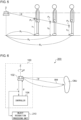
- Figs. 1A and 1B are diagrams for explaining sensing provided by LiDAR.
- a LiDAR 2 scans a scan beam BM in the horizontal direction with a fixed elevation angle ⁇ so as to measure the distances r up to multiple measurement points P on an object OBJ.
- Fig. 1B shows a state in which the scan line SL passes through the knees of a pedestrian.
- the shape of the object OBJ is measured along multiple scan lines SL with several different elevation angles ⁇ . This allows the class of the object OBJ to be identified.
- Fig. 2 is a diagram for explaining the sensing provided by two LiDARs having different specifications.
- Scan beams BM 1 and BM 2 represent the outputs of the two LiDARs having different specifications.
- the scan beams BM with different elevation angles ⁇ are used to scan different portions of the object OBJ, thereby providing different images.
- the in-vehicle LiDAR requires careful installation angle alignment when it is installed on a vehicle. In other words, this restricts the degree of freedom in mounting the LiDAR.
- Fig. 3 is a diagram for explaining a problem 2.
- Fig. 3 shows a virtual screen SCRN.
- the virtual screen SCRN is a flat plane.
- a center measurement point P 1 is defined such that it provides a minimum horizontal distance R 1 up to the LiDAR2.
- the horizontal distance R becomes larger according to an increase in the distance from the center up to a given measurement point such as P 2 , P 3 , or the like. As a result, there is a difference in the height h between the multiple measurement points P.
- Fig. 4A is a diagram showing multiple scan lines when a vehicle is measured from a side.
- the elevation angle ⁇ 0°
- the height of the scan line SL is maintained at a constant level.
- the elevation angle ⁇ is non-zero
- the height of the scan line changes according to the scan angle ⁇ . That is to say, in a case of measuring an object such as a vehicle having a large width, this leads to distortion of a measured image at both ends. This is the problem 2.
- Fig.4B is a diagram showing multiple scan lines when a pedestrian is measured. There is a difference in portions measured by the multiple scan lines between a case in which an object OBJ such as a pedestrian having a small width is positioned at the center and a case in which such an object OBJ is positioned at an end. This is the problem 3.
- Fig. 5 is a diagram for explaining the problem 4.
- Fig. 5 is a diagram showing the dependence of the height h on the horizontal distance R when the scan angle ⁇ is set to a fixed angle.
- the portion measured by the same scan line changes according to a change in the horizontal distance R.
- the abdomen, upper legs, and knees are measured using the same beam at the horizontal distances R 1 , R 2 , and R 3 , respectively.
- the problems 1 through 4 introduce significant complexity to the design of an identifier configured to identify the class (category) of the object OBJ. Otherwise, in some cases, such problems lead to degradation of identification probability in the final stage.
- the precision of object recognition based on the point group data generated by the LiDAR increases according to an increase in the resolution of the point group data. However, this involves a drastic increase in calculation costs.
- the present invention has been made in view of such a situation. Accordingly, it is an exemplary purpose of an embodiment of the present invention to provide a recognition sensor or a system that solves at least one from among the above-described problems.
- this arrangement is capable of determining the height of the correction point on the scan line. This arrangement allows at least one of the problems described above to be solved.
- the controller may perform preliminary measurement for a correction point selected from among the multiple measurement points. Also, the elevation angle to be used in the main measurement may be calculated based on the distance and the elevation angle acquired in the preliminary measurement.
- controller may correct the elevation angle for each of the measurement points.
- the controller may correct the elevation angle at least once for each scan line and for each object.
- the controller may correct the elevation angle every time the scan is advanced by a predetermined horizontal angle or for every predetermined number of measurement points.
- the controller may correct the elevation angle for each of the measurement points for each scan line.
- the motor vehicle may comprise any one of the above-described recognition sensors.
- the automotive lamp may comprise any one of the above-described recognition sensors.
- any combination of the components described above, any component of the present invention, or any manifestation thereof, may be mutually substituted between a method, apparatus, system, and so forth, which are also effective as an embodiment of the present invention.
- such an arrangement is capable of solving at least one of the above-described problems.
- Fig. 6 is a block diagram showing an object recognition system 200 including a recognition sensor 100 according to a first embodiment.
- the recognition sensor 100 includes a three-dimensional sensor 102 and a controller 104.
- the three-dimensional sensor 102 scans a scan beam BM in the horizontal direction (around the Z axis) so as to measure distances up to multiple measurement points.
- a line that passes through the multiple measurement points acquired for one scan will be referred to as a "scan line SL".
- the data acquired in this step will be referred to as "scan data”.
- the method for identifying an object with small irregularities, such as a pedestrian, with high precision is not restricted in particular. However, in this case, a LiDAR is preferably employed.
- the number of scan lines N represents the so-called resolution in the vertical direction.
- the three-dimensional sensor 102 is configured to be capable of adjusting the elevation angle ⁇ .
- the control of the elevation angle ⁇ is supported in order to select the scan line.
- the elevation angle can be selected from N elevation angles ⁇ 1 through ⁇ N determined beforehand.
- the elevation angle ⁇ is maintained at a constant value during the scan operation.
- N represents the number of scan lines.
- Fig. 7 is a diagram showing an example of a LiDAR configured as the three-dimensional sensor 102.
- the LiDAR 300 shown in Fig. 7 includes a MEMS scanner.
- the MEMS scanner includes a mirror 302 and actuators 304 and 306.
- the mirror 302 reflects a beam emitted from an unshown light source.
- the actuator 304 rotates the mirror 302 around a first axis.
- the actuator 306 rotates the mirror 302 around a second axis together with the actuator 304 that mounts the mirror 302.
- the rotation around the first axis corresponds to the control of the scan angle ⁇ .
- the rotation around the second axis corresponds to the control of the elevation angle ⁇ .
- the configuration of the three-dimensional sensor 102 is not restricted to the example shown in Fig. 7 . Rather, known devices or devices that will become available in the future may be employed. For example, non-mechanical devices such as phased-array devices or microprism devices may be employed. Alternatively, mechanical devices may be employed, examples of which include devices employing the above-described MEMS mirrors and devices employing motor-driven mirrors.
- the control of the elevation angle ⁇ is used to correct the height of each scan line or to correct distortion of the scan lines.
- the controller 104 selects at least one from among the multiple measurement points as a correction point. Furthermore, the controller 104 corrects the elevation angle ⁇ of the three-dimensional sensor 102 such that the height of the correction point approaches a predetermined value h REF .
- the controller 104 receives, as input data, the distance measurement data that represents the distance r up to the correction point.
- the height of the correction point can be geometrically calculated based on the elevation angle ⁇ and the distance measurement data.
- Fig. 8 is a diagram for explaining correction of the elevation angle ⁇ of the three-dimensional sensor 102.
- Fig. 8 shows the processing for a single correction point on a single scan line.
- the recognition sensor 100 performs preliminary measurement for the correction processing.
- the elevation angle ⁇ is set to an initial value ⁇ INIT determined beforehand.
- the initial value ⁇ INIT may be a unique value determined for a given scan line.
- the scan beam BM INIT scanned in the preliminary measurement is indicated by the solid line.
- the distance r up to the object OBJ is measured.
- the height h is defined with the light source for the three-dimensional sensor 102 as a reference.
- the horizontal distance R up to the object OBJ can be calculated based on Expression (1) using the measured distance r and the initial elevation angle ⁇ INIT .
- R r • cos ⁇ INIT
- the controller 104 calculates the elevation angle ⁇ CMP to be used in the main measurement based on based on the distance r acquired in the preliminary measurement and the elevation angle ⁇ INIT set in the preliminary measurement.
- the scan beam BM CMP emitted with the corrected elevation angle ⁇ CMP is required to cross the object OBJ at the reference height h REF . Accordingly, the following Expression (2) holds true.
- tan ⁇ CMP h REF / R
- the three-dimensional sensor 102 sets the elevation angle to ⁇ CMP , and measures the distance r' up to the object OBJ again.
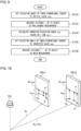
- Fig. 9 is a flowchart showing the correction processing for the elevation angle ⁇ of the three-dimensional sensor 102.
- the elevation angle ⁇ of the three-dimensional sensor 102 is set to the initial value ⁇ INIT (S100).
- the three-dimensional sensor 102 measures the distance r up to the object OBJ (S102).
- the corrected elevation angle ⁇ CMP is calculated based on the distance r acquired in the preliminary measurement and the initial value of the elevation angle ⁇ INIT (S104).
- the corrected elevation angle ⁇ CMP is set for the three-dimensional sensor 102 (S106).
- the distance r' up to the object is measured (S108).
- Fig. 10 is a diagram for explaining the correction according to the first example. Description will be made below directing attention to a single scan line.
- the scan line SL INIT provided with a constant elevation angle is indicated by the line of dashes and dots. Description will be made assuming that there are two objects OBJ 1 and OBJ 2 at different horizontal distances R 1 and R 2 , respectively. Here, the relation R 2 > R 1 holds true.
- the objects OBJ 1 and OBJ 2 are each a flat plane, and that distortion occurs in the scan line SL INIT when the elevation angle ⁇ is controlled to be maintained at a constant value. Furthermore, the scan line SL INIT formed on the object OBJ 2 positioned at a far distance passes through the measurement points at heights that are smaller than those of the scan line SL INIT formed on the object OBJ 1 positioned at a near distance.
- the corrected scan line SL CMP is indicated by the solid line.
- the scan beam hits the measurement points P INIT on the scan line SL INIT before the correction.
- the measurement points P CMP are shifted to positions at the predetermined height h REF .
- the scan line SL CMP is provided at a substantially constant height. This reduces the occurrence of distortion of the image. That is to say, this example is capable of solving the problem 2 relating to Fig. 4A and the problem 3 relating to Fig. 4B .
- the controller 104 controls the elevation angle ⁇ of the three-dimensional sensor 102 such that the height of each scan line is maintained at a constant level independently of the scan angle ⁇ .
- this arrangement is capable of setting the height of each measurement point P CMP to the uniform height h REF regardless of a difference between the horizontal distances R 1 and R 2 . That is to say, this arrangement is capable of solving the problem 4 described with reference to Fig. 4 .
- the controller 104 controls the elevation angle of the three-dimensional sensor such that the height of each measurement point approaches the predetermined value h REF regardless of the horizontal distance R up to the measurement point.
- this arrangement is capable of solving the problem 1.
- this arrangement is capable of raising the degree of freedom in installing the LiDAR in a vehicle.
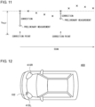
- Fig. 11 is a diagram for explaining correction processing according to a second example.
- multiple measurement points are selected as the correction points in the scan direction in a discrete manner.
- the measurement points between a given correction point and the next correction point are measured using the corrected angle ⁇ CMP acquired in the immediately previous correction.
- At least one measurement point may preferably be set for the object OBJ in a discrete manner, for example.
- a new object OBJ may be detected based on a large discontinuity in the distance r.
- this arrangement is not capable of providing a perfectly uniform height h.
- this arrangement is capable of suppressing fluctuation of the height as compared with the measurement in a case in which the elevation angle is controlled to be maintained at a constant value.
- By correcting the elevation angle for every object OBJ such an arrangement is capable of solving the problem 3 relating to Fig. 4B and the problem 4 relating to Fig. 5 .
- this arrangement is not capable of solving the problem relating to Fig. 4A .
- this arrangement may preferably measure a similar distorted image in machine learning.
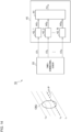
- Fig. 13 is a block diagram showing an automotive lamp 500 including the object recognition system 200.
- the automotive lamp 500 includes a light source 502, a lighting circuit 504, an optical system 506, and a lighting device ECU 508. Furthermore, the automotive lamp 500 is provided with the object recognition system 200.
- the information with respect to the object OBJ detected by the object recognition processing unit 210 may be used to support light distribution control of the automotive lamp 500 (ADB: Adaptive Driving Beam).
- ADB Adaptive Driving Beam
- the lighting device ECU 508 generates a suitable light distribution pattern based on the information with respect to the class of the object OBJ generated by the object recognition processing unit 210 and the position of the object OBJ.
- the lighting circuit 504 and the optical system 506 operate so as to provide the light distribution pattern thus generated by the lighting device ECU 508.
- Fig. 14 is a block diagram showing an object recognition system 10 according to a second embodiment.
- the object recognition system 10 is configured as an in-vehicle system to be mounted on a vehicle such as an automobile, motorcycle, or the like.
- the object recognition system 10 judges the class (which is also referred to as a "category") of the object OBJ in the vicinity of the vehicle.
- examples of the class of the object include a pedestrian, bicycle, automobile, pole, and the like.
- a pedestrian as viewed from the front, a pedestrian as viewed from the rear, and a pedestrian as viewed from the side may be classified and defined as the same class of object. The same can be said of an automobile and bicycle. In the present embodiment, this definition is employed.
- the object OBJ is defined such that it has multiple portions (which will be referred to as “categories or sub-categories") positioned at different heights.
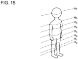
- Fig. 15 is a diagram showing an example of the multiple portions defined with respect to a pedestrian.
- M portions H 0 through H M-1 are defined.
- H 0 indicates the knees
- H 1 indicates the upper above-the-knee portions
- H 2 indicates the upper legs
- H 3 indicates the waist
- H 4 indicates the abdomen
- H 5 indicates the chest
- H 6 indicates the shoulders
- H 7 indicates the face.
- multiple portions B 0 through B 7 are defined at different heights.
- multiple portions C 0 through C 7 are defined at different heights.
- multiple portions P 0 through P 7 can be defined at different heights. However, there is substantially no difference between portions regardless of height. Accordingly, there is no need to distinguish the multiple portions P 0 through P 7 . That is to say, the data of a pole is handled as a single output P 0 .
- Figs. 16A through 16D are diagrams showing multiple items of line data of a pedestrian, bicycle, automobile, and pole acquired by the three-dimensional sensor 20.
- the multiple items of line data represent the shapes of multiple portions defined beforehand.
- the processing device 40 generates intermediate data MD with respect to the class of the object OBJ and the portion thereof for each item of line data LD.
- the intermediate data MD i may indicate the class of the object OBJ and the portion thereof that corresponds to the line data LD i (horizontal line L i ) in a statistical manner.
- the processing device 40 includes multiple first calculation units 42_1 through 42_N and a second calculation unit 44.
- the blocks indicated by the calculation units 42 and 44 do not necessarily mean that such blocks are configured as independent hardware blocks.
- the multiple calculation units 42 and 44 may correspond to the single core.
- each core may function as a corresponding one of the multiple calculation units 42 and 44.
- the i-th (1 ⁇ i ⁇ N) calculation unit 42_i processes the corresponding line data LD i so as to generate the intermediate data MD i .
- the second calculation unit 44 integrates the intermediate data MD 1 through MD N generated by the multiple first calculation units 42_1 through 42_N so as to generate the final data FD.
- Fig. 17 is a block diagram showing an example configuration of the first neural network NN 1 .
- the first neural network NN 1 is configured including an input layer 50, three intermediate layers (hidden layers) 52, and an output layer 54.
- the number of units of the input layer 50 is determined according to the number of sample points for each line, and specifically, is designed to be 5,200.
- the three intermediate layers are designed with the number of units of 200, 100, and 50, respectively.
- the intermediate layers 52 support transformation using affine transformation and a sigmoid function.
- the output layer 54 supports probability calculation using affine transformation and a softmax function.
- the intermediate data MD i includes multiple items of data Human-0th through Human-7th, Car-0th through Car-7th, Bicycle-0th through Bicycle-7th, and Pole-all, which indicate the probabilities of a given portion to be identified matching the portions H 0 through H 7 of a pedestrian, the portions C 0 through C 7 of an automobile, the portions B 0 through B 7 of a bicycle, and the portion P 0 of a pole, respectively.
- Fig. 18 is a block diagram showing an example configuration of the second neural network NN 2 .
- the second neural network NN 2 is configured including an input layer 60, a single intermediate layer 62, and an output layer 64.
- the intermediate layer 62 is configured as a single layer designed such that the number of units is 50.
- the output layer 64 is designed so as to define four categories, i.e., the pedestrian category (Human), the automobile category (Car), the bicycle category (Bicycle), and the pole category (Pole). That is to say, the final data FD includes four items of data Human, Car, Bicycle, and Pole that correspond to the probabilities of a given object OBJ matching a pedestrian, automobile, bicycle, and pole, respectively.
- the first neural network NN 1 and the second neural network NN 2 are designed with the Adam method as the parameter update method, with a learning rate of 0.01, and with the number of iterations as 20,000.
- extraction, shifting, and normalization are preferably performed.
- Figs. 19A through 19C are diagrams for explaining the extraction of the object.
- Fig. 19A is a diagram showing an automobile employed as the object.
- Fig. 19B shows multiple items of line data LD 1 through LD 8 obtained when an image of the object shown in Fig. 19A is captured by means of the LiDAR.
- Fig. 19C shows the line data LD 1 through LD 8 extracted such that they include the object data.
- Shifting is data shifting processing for shifting the object such that it is positioned at the center.
- Normalization is processing for dividing the distance data by a predetermined value. For example, as the predetermined value, the distance (reference distance) between the three-dimensional sensor 20 and a predetermined portion of the object OBJ set in the learning may be employed. This processing normalizes the line data such that it becomes a value in the vicinity of 1.
- Figs. 20A through 20C are diagrams for explaining a first learning method.
- the learning data is acquired by measuring multiple objects by means of LiDAR. Specifically, the object candidates (pedestrian, automobile, pole, person riding a bicycle, etc.) to be identified are measured under different conditions (e.g., at various distances and in various directions), so as to prepare frame data FD 1 , FD 2 , ..., for learning.
- the effective line data in which the line crosses the object may be used.
- the frame data FD 1 is acquired for a pedestrian
- the lowermost two items of line data LD 11 and LD 12 cross the ground, and do not cross the pedestrian. Accordingly, judgment may be made that the line data LD 11 and LD 12 are not used in the learning.
- first calculation unit 42 learning is performed for the first calculation unit (first neural network) 42.
- first calculation unit 42 multiple items of effective line data LD ij included in the multiple items of frame data are individually input to the first calculation unit 42 together with teaching data TD ij .
- the learning results thus obtained with respect to such a single first calculation unit 42 are used for all the first calculation units 42.
- learning is performed for the second calculation unit 44.
- the multiple first calculation units 42 are coupled to the second calculation unit (second neural network) 44.
- the processing device 40 receives multiple items of frame data FD 1 , FD 2 , ..., and outputs multiple items of intermediate data MD 1 through MD 8 from the processing device 40.
- a set of multiple items of intermediate data MD 1 through MD 8 is generated for each frame FD i by means of the multiple first calculation units 42, which is supplied to the second calculation unit 44 configured as a downstream stage.
- the second calculation unit 44 receives the teaching data TD i that indicates the class of the object included in the current frame data FD i in addition to the set of the intermediate data MD 1 through MD 6 .
- the LiDAR employed in this investigation was configured to provide eight horizontal lines.
- the horizontal lines were designed with irradiation angles of -18.25°, - 15.42°, - 12.49°, -9.46°, -6.36°, -3.19°, 0°, and 3.2°, in this order from the bottom (angular resolution in the vertical direction).
- the angular resolution in the horizontal direction is designed to be 0.035°.
- Figs. 21A and 21B are diagrams for explaining image capture of a pedestrian. Description will be made regarding an example in which the distance (reference distance) from the center of the LiDAR up to the object OBJ is 3 m. Furthermore, description will be made assuming that the pedestrian sample is an adult male pedestrian with a height of 166 cm, and the object image is captured in nine directions (0°, 22.5°, 45°, 67.5°, 90°, 112.5°, 135°, 157.5°, and 180°). It should be noted that the direction in which the LiDAR faces the front (face, headlamp) of the object OBJ is defined to be 0°. Regarding the pedestrian, the LiDAR is set with a tilt angle (elevation angle) of 7° in the vertical direction such that the eight horizontal lines match the eight portions H 0 through H 7 shown in Fig. 15 .
- image data was acquired in a state in which a person was mounted on a stopped bicycle.
- the image data was acquired in nine directions in the same manner as in the image data acquisition for the pedestrian.
- image data was acquired for a single class of automobile in three directions (0°, 90°, and 180°).
- image data was acquired for six pole samples in an arbitrary direction.
- the machine learning was performed for the pedestrian and the bicycle with 3,600 frames of training data, for the automobile with 3,000 frames of training data, and for the pole with 1,700 frames of training data.
- the learning method described with reference to Figs. 20A through 20C was employed.
- Fig. 22 is a diagram showing the accuracy rate for the classification of 25 categories (sub-categories) provided by the first neural network NN 1 .
- the other categories represent the accuracy rates for the classification of the respective portions of the pedestrian, automobile, bicycle, and pole.
- Fig. 23 is a diagram showing the accuracy rates for the classification of the four categories provided by the second neural network NN 2 .
- the other categories represent the accuracy rates for the classification of the pedestrian (Human), automobile (Car), bicycle (Bicycle), and pole (Pole).
- this arrangement provides an accuracy rate of 100% for the pedestrian (Human), automobile (Car), and pole (Pole). However, this arrangement provides an accuracy rate of only 97.8% for only the bicycle (Bicycle). Accordingly, it can be understood that the total accuracy rate is affected by the degraded accuracy rate for the bicycle.
- this arrangement is capable of judging the class of the object with a dramatically high accuracy rate using only eight horizontal lines.
- this arrangement requires only a small number of horizontal lines, i.e., only eight lines, thereby allowing the processing capacity required for the processing device 40 to be reduced.
- the effects were evaluated with a fixed distance of 3 m between the object and the LiDAR. In actuality, the distance varies. Accordingly, the learning may preferably be performed for each range after various distances are classified into multiple ranges.
- Fig. 24 is a block diagram showing an automobile 600 including the object recognition system 10.
- the automobile 600 includes headlamps 602L and 602R. From among the components of the object recognition system 10, at least the three-dimensional sensor 20 is built into at least one from among the headlamps 602L and 602R. Each headlamp 602 is positioned at a frontmost end of the vehicle body, which is most advantageous as a position where the three-dimensional sensor 20 is to be installed for detecting an object in the vicinity.
- the processing device 40 may be built into the headlamp 602. Also, the processing device 40 may be provided on the vehicle side. For example, from among the functions of the processing device 40, the function of generating the intermediate data may be provided by an internal component of the headlamp 602. Also, the function of generating the final data may be provided by another component on the vehicle side.
- Fig. 25 is a block diagram showing an automotive lamp 700 including the object recognition system 10.
- the automotive lamp 700 includes a light source 702, a lighting circuit 704, and an optical system 706. Furthermore, the automotive lamp 700 includes the three-dimensional sensor 20 and the processing device 40.
- the information with respect to the object OBJ detected by the processing device 40 is transmitted to the in-vehicle ECU 604.
- the in-vehicle ECU may support autonomous driving based on the information thus transmitted.
- the information with respect to the object OBJ detected by the processing device 40 may be used to support the light distribution control operation of the automotive lamp 700.
- the lighting device ECU 708 generates a suitable light distribution pattern based on the information with respect to the class of the object OBJ and the position thereof thus generated by the processing device 40.
- the lighting circuit 704 and the optical system 706 operate so as to provide the light distribution pattern generated by the lighting device ECU 708.
- this arrangement involves learning that strongly depends on the installation of the LiDAR (height, elevation angle, or the distance up to the object).
- Fig. 26A shows a case in which the LiDAR is installed at a height of 145 cm in the learning. In this case, the lower three items of line data are ineffective. That is to say, the line data LD 4 through LD 8 , which are the fourth line data through the eighth line data from the bottom, are used for the learning.
- the LiDAR is installed at a height of 70 cm, which is lower than that in the learning. Furthermore, description will be made assuming that the distance between the pedestrian and the LiDAR is smaller than that in the learning.
- the line data LD 1 through LD 3 match no particular portion (no particular sub-category).
- Fig. 26C shows the final data obtained by the object recognition system 10 in a situation shown in Fig. 26B in a case in which it has learned using the first learning method.
- the object must be identified as a pedestrian.
- false identification is obtained that there is a higher probability of other objects that differ from the pedestrian. It can be considered that this is because, with the first learning method, the classification supported by the second calculation unit 44 strongly depends on the definition order and combination of the sub-categories. That is to say, in a case of employing the first learning method, in some cases, such an arrangement has the potential to restrict the height at which the three-dimensional sensor is to be installed in actual use stage due to the height that was used in the learning stage.
- a second learning method is designed to have a function for reducing such a restriction.
- Fig. 27 is a diagram for explaining the learning process for the second calculation unit 44 using the second learning method.
- this arrangement instructs the second calculation unit 44 to learn while changing the correspondence relation 46 between the outputs of the multiple first calculation units 42 that have learned and multiple input nodes I 1 through Is of the second calculation unit 44.
- the correspondence relation 46 may be changed at random for each frame data FD i .
- this arrangement may support the learning for each frame data FD i while switching the correspondence relation between multiple patterns.
- N 8
- there are 56 ( 8 ⁇ 7) input/output combinations. Accordingly, this arrangement may support the learning for each frame data with respect to all the combinations.
- Fig. 28 is a diagram for explaining the effect of the second learning method.
- Fig. 28 shows the final data FD obtained by the object recognition system 10 that has learned using the second learning method in a case in which a pedestrian is assumed in the situation shown in Fig. 26B .
- This arrangement allows the accuracy rate for the identification of a pedestrian to be raised as compared with the final data shown in Fig. 26C obtained using the first learning method.
- the learning step for the second calculation unit 44 the correspondence relation between the multiple first calculation units 42 and the multiple inputs of the second calculation unit 44 is changed. This arrangement allows the degree of freedom in installing the three-dimensional sensor such as the LiDAR or the like.
- Fig. 29 is a block diagram showing an object recognition system 10A according to a modification.
- first calculation units 42A are configured as a convolutional neural network.
- a convolutional neural network handles a two-dimensional image of N ⁇ N pixels.
- the convolutional neural network handles one-dimensional line data as a processing target, which is a new idea.
- the convolutional neural network is configured as a combination of a convolutional layer and a pooling layer.
- N is set to a value on the order of 4 to 12 giving consideration to the calculation power of the processing device 40 and the required object OBJ identification capability.
- the object may be defined as a different class (category) for each orientation as viewed from the user's vehicle. That is to say, the same object is identified as a different class according to the orientation thereof, e.g., whether or not the object is positioned with a face-to-face orientation with respect to the user's vehicle. This is because such identification is advantageous in estimating the object OBJ moving direction.
- the processing device 40 may be configured of only a hardware component using an FPGA or the like.
- the object recognition system 10 may be fixedly installed on transportation infrastructure such as a traffic light, traffic sign, or the like. That is to say, the present invention is applicable to a fixed-point observation application.
- the above-described embodiments show only an aspect of the mechanisms and applications of the present invention. Rather, various modifications and various changes in the layout can be made without departing from the spirit and scope of the present invention defined in appended claims.
- the present invention is applicable to a recognition sensor that detects the shape of an object.
Landscapes
- Physics & Mathematics (AREA)
- Engineering & Computer Science (AREA)
- Electromagnetism (AREA)
- General Physics & Mathematics (AREA)
- Radar, Positioning & Navigation (AREA)
- Remote Sensing (AREA)
- Computer Networks & Wireless Communication (AREA)
- Computer Vision & Pattern Recognition (AREA)
- Theoretical Computer Science (AREA)
- Mechanical Engineering (AREA)
- Optical Radar Systems And Details Thereof (AREA)
- Traffic Control Systems (AREA)
- Lighting Device Outwards From Vehicle And Optical Signal (AREA)
- Image Analysis (AREA)
Claims (8)
- Erkennungssensor (100) für ein Kraftfahrzeug, wobei der Erkennungssensor umfasst:einen dreidimensionalen Sensor (102), der so ausgelegt ist, dass er einen Höhenwinkel (φ) einstellen kann;eine Verarbeitungsvorrichtung (40) mit einem neuronalen Netz für maschinelles Lernen, die so ausgelegt ist, dass sie die Klasse eines Objekts identifiziert; undeine Steuerung (104), die so ausgelegt ist, dass sie den Höhenwinkel des dreidimensionalen Sensors so steuert, dass eine Höhe eines Korrekturpunktes korrigiert wird, dadurch gekennzeichnet, dassder dreidimensionale Sensor (102) so ausgelegt ist, dass er eine Vielzahl von Liniendaten erzeugt, die einer Vielzahl horizontaler Abtastlinien (scan lines, SL) mit unterschiedlicher Höhe entsprechen, und in der Lage ist, den Höhenwinkel (φ) einzustellen, um eine aus der Vielzahl horizontaler Abtastlinien auszuwählen,wobei jede Abtastlinie eine Vielzahl von Messpunkten umfasst und die Steuerung so ausgelegt ist, dass sie einen der Vielzahl von Messpunkten als den Korrekturpunkt auswählt, undwobei für jede Abtastlinie die Steuerung ferner so ausgelegt ist, dass sie Abstandsmessdaten empfängt, die den Abstand zu dem Korrekturpunkt angeben, die Höhe des Korrekturpunktes auf Grundlage des Höhenwinkels und der Abstandsmessdaten berechnet undden Höhenwinkel des dreidimensionalen Sensors so korrigiert, dass sich die Höhe des Korrekturpunktes einem vorbestimmten Wert annähert.
- Erkennungssensor nach Anspruch 1, wobei die Steuerung (104) so ausgelegt ist, dass sie den dreidimensionalen Sensor (102) veranlasst, eine vorläufige Messung für den Korrekturpunkt durchzuführen,
und die Steuerung (104) so ausgelegt ist, dass sie den in der Hauptmessung zu verwendenden Höhenwinkel auf Grundlage des gemessenen Abstands, der den Abstand zu dem Korrekturpunkt in der vorläufigen Messung angibt, und des in der vorläufigen Messung verwendeten Höhenwinkels berechnet. - Erkennungssensor nach einem der Ansprüche 1 und 2, wobei für jede Abtastlinie (SL) alle Messpunkte als Korrekturpunkte verwendet werden und die Steuerung (104) den Höhenwinkel für jeden der Messpunkte korrigiert.
- Erkennungssensor nach einem der Ansprüche 1 bis 3, wobei die Steuerung (104) den Höhenwinkel mindestens einmal für jede Abtastlinie und für jedes Objekt (OBJ) korrigiert.
- Erkennungssensor nach einem der Ansprüche 1 bis 4, wobei der vorbestimmte Wert durch eine Höhe der Abtastlinie (SL) angenähert wird, die als Lerndaten für das maschinelle Lernen des neuronalen Netzes verwendet wird.
- Kraftfahrzeug (400), das den Erkennungssensor (2) nach einem der Ansprüche 1 bis 5 umfasst.
- Kraftfahrzeugleuchte (410L; 410R), die den Erkennungssensor (2) nach einem der Ansprüche 1 bis 5 umfasst.
- Steuerverfahren für einen Erkennungssensor für ein Kraftfahrzeug, wobei der Erkennungssensor einen dreidimensionalen Sensor umfasst, wobei der dreidimensionale Sensor so ausgelegt ist, dass er eine Vielzahl von Liniendaten erzeugt, die einer Vielzahl horizontaler Abtastlinien (SL) mit unterschiedlicher Höhe entsprechen, und in der Lage ist, in einer horizontalen Richtung abzutasten, und in der Lage ist, einen Höhenwinkel einzustellen, um eine aus der Vielzahl horizontaler Abtastlinien davon auszuwählen,wobei der dreidimensionale Sensor ferner eine Verarbeitungsvorrichtung (40) implementiert, die ein neuronales Netzwerk für maschinelles Lernen aufweist und so ausgelegt ist, dass sie die Klasse eines Objekts auf Grundlage der Vielzahl von Liniendaten identifiziert; sowieeine Steuerung (104), die so ausgelegt ist, dass sie den Höhenwinkel des dreidimensionalen Sensors so steuert, dass die jeweiligen Höhen der Vielzahl horizontaler Abtastlinien (SL) korrigiert werden, wobei jede Abtastlinie eine Vielzahl von Messpunkten umfasst;wobei das Steuerverfahren die folgenden Schritte umfasst:Auswählen eines der Vielzahl von Messpunkten als Korrekturpunkt durch die Steuerung,Empfangen von Abstandsmessdaten, die den Abstand zu dem Korrekturpunkt angeben, durch die Steuerung und für jede Abtastlinie,Berechnen der Höhe des Korrekturpunktes durch die Steuerung auf Grundlage des Höhenwinkels und der Abstandsmessdaten, undKorrigieren des Höhenwinkels des dreidimensionalen Sensors durch die Steuerung so, dass sich die Höhe des Korrekturpunktes einem vorbestimmten Wert annähert.
Applications Claiming Priority (4)
| Application Number | Priority Date | Filing Date | Title |
|---|---|---|---|
| JP2017157944 | 2017-08-18 | ||
| JP2017162607 | 2017-08-25 | ||
| JP2018043457 | 2018-03-09 | ||
| PCT/JP2018/028978 WO2019035363A1 (ja) | 2017-08-18 | 2018-08-02 | 認識センサおよびその制御方法、自動車、車両用灯具、オブジェクト識別システム、オブジェクトの識別方法 |
Publications (3)
| Publication Number | Publication Date |
|---|---|
| EP3671279A1 EP3671279A1 (de) | 2020-06-24 |
| EP3671279A4 EP3671279A4 (de) | 2021-03-31 |
| EP3671279B1 true EP3671279B1 (de) | 2024-08-14 |
Family
ID=65362508
Family Applications (1)
| Application Number | Title | Priority Date | Filing Date |
|---|---|---|---|
| EP18846493.7A Active EP3671279B1 (de) | 2017-08-18 | 2018-08-02 | Erkennungssensor, steuerverfahren dafür, kraftfahrzeug, fahrzeugleuchte, objektidentifizierungssystem und objektidentifizierungsverfahren |
Country Status (5)
| Country | Link |
|---|---|
| US (1) | US11754714B2 (de) |
| EP (1) | EP3671279B1 (de) |
| JP (1) | JP7193464B2 (de) |
| CN (1) | CN111033316B (de) |
| WO (1) | WO2019035363A1 (de) |
Families Citing this family (5)
| Publication number | Priority date | Publication date | Assignee | Title |
|---|---|---|---|---|
| CN111919139B (zh) * | 2018-03-15 | 2024-10-15 | 株式会社小糸制作所 | 对象识别系统、汽车、车辆用灯具、对象的种类的识别方法 |
| JP2020154053A (ja) * | 2019-03-18 | 2020-09-24 | 株式会社リコー | 光偏向素子及びその製造方法、光偏向システム、光走査システム |
| MX2023000409A (es) | 2020-07-08 | 2023-02-02 | Crown Equip Corp | Calibracion de dispositivo de medicion de distancia y alcance de un vehiculo industrial. |
| KR20220077519A (ko) * | 2020-12-02 | 2022-06-09 | 현대자동차주식회사 | 라이다 센서를 이용한 고도 구조물 인지 장치 및 방법 |
| CN116964599B (zh) * | 2022-02-25 | 2026-03-10 | 厦门大学 | 基于激光雷达的三维人体动作捕捉方法、训练方法及系统 |
Family Cites Families (37)
| Publication number | Priority date | Publication date | Assignee | Title |
|---|---|---|---|---|
| DE3129492A1 (de) * | 1981-07-27 | 1983-02-10 | Siemens AG, 1000 Berlin und 8000 München | 3d-luftraum-ueberwachungsradar |
| US7284769B2 (en) | 1995-06-07 | 2007-10-23 | Automotive Technologies International, Inc. | Method and apparatus for sensing a vehicle crash |
| US5983161A (en) * | 1993-08-11 | 1999-11-09 | Lemelson; Jerome H. | GPS vehicle collision avoidance warning and control system and method |
| US7769513B2 (en) * | 2002-09-03 | 2010-08-03 | Automotive Technologies International, Inc. | Image processing for vehicular applications applying edge detection technique |
| US7852462B2 (en) | 2000-05-08 | 2010-12-14 | Automotive Technologies International, Inc. | Vehicular component control methods based on blind spot monitoring |
| JP3472815B2 (ja) * | 2000-10-31 | 2003-12-02 | 国土交通省国土技術政策総合研究所長 | 横断歩行者検出方法 |
| JP2002236178A (ja) * | 2001-02-07 | 2002-08-23 | Honda Motor Co Ltd | 移動体における物体検知装置 |
| US20040024660A1 (en) * | 2002-08-05 | 2004-02-05 | General Electric Company | System and method for providing asset management and tracking capabilities |
| JP2005043247A (ja) * | 2003-07-23 | 2005-02-17 | Nissan Motor Co Ltd | 先行車両検出装置 |
| JP2005316888A (ja) * | 2004-04-30 | 2005-11-10 | Japan Science & Technology Agency | 顔認識システム |
| JP4354343B2 (ja) * | 2004-06-15 | 2009-10-28 | 株式会社トプコン | 位置測定システム |
| JP4428208B2 (ja) * | 2004-11-16 | 2010-03-10 | 株式会社デンソー | 車両用物体認識装置 |
| JP4244964B2 (ja) * | 2005-06-06 | 2009-03-25 | オムロン株式会社 | 車両用測距装置 |
| JP2009098023A (ja) | 2007-10-17 | 2009-05-07 | Toyota Motor Corp | 物体検出装置及び物体検出方法 |
| JP2009168472A (ja) * | 2008-01-10 | 2009-07-30 | Zenrin Co Ltd | レーザースキャナのキャリブレーション装置及びキャリブレーション方法 |
| JP5278728B2 (ja) * | 2008-02-28 | 2013-09-04 | アイシン精機株式会社 | 距離画像センサの校正装置及び校正方法 |
| CN101408933A (zh) * | 2008-05-21 | 2009-04-15 | 浙江师范大学 | 基于粗网格特征提取和bp神经网络的车牌字符识别方法 |
| JP2011247619A (ja) * | 2010-05-24 | 2011-12-08 | Sanyo Electric Co Ltd | ビーム照射装置 |
| JP5751014B2 (ja) * | 2010-05-28 | 2015-07-22 | リコーイメージング株式会社 | 天体自動追尾撮影方法及び天体自動追尾撮影装置 |
| US9267792B2 (en) * | 2013-01-21 | 2016-02-23 | Systèmes Pavemetrics Inc. | Method and apparatus for compensating lateral displacements and low speed variations in the measure of a longitudinal profile of a surface |
| KR102027771B1 (ko) * | 2013-01-31 | 2019-10-04 | 한국전자통신연구원 | 차량 속도 적응형 장애물 검출 장치 및 방법 |
| US9113154B2 (en) * | 2013-07-10 | 2015-08-18 | Faro Technologies, Inc. | Three-dimensional measurement device having three-dimensional overview camera |
| JP2015197329A (ja) * | 2014-03-31 | 2015-11-09 | 三菱重工業株式会社 | データ伝送システム、データ伝送装置、データ伝送方法、及びデータ伝送プログラム |
| CN104318581A (zh) * | 2014-11-14 | 2015-01-28 | 成都华川电装有限责任公司 | 车载预警系统摄像头标定方法 |
| DE102014225344A1 (de) * | 2014-12-10 | 2016-06-16 | Bayerische Motoren Werke Aktiengesellschaft | Kraftfahrzeug |
| US9576185B1 (en) | 2015-09-14 | 2017-02-21 | Toyota Motor Engineering & Manufacturing North America, Inc. | Classifying objects detected by 3D sensors for autonomous vehicle operation |
| WO2017125925A1 (en) * | 2016-01-19 | 2017-07-27 | Speculo Systems Ltd | Method and system for real-time detection and location of multiple independently moving objects |
| EP3203263B1 (de) * | 2016-02-03 | 2018-04-18 | Sick Ag | Optoelektronischer sensor und verfahren zum erfassen von objekten |
| US20170303819A1 (en) * | 2016-04-21 | 2017-10-26 | KHN Solutions, Inc. | Method and system for alcohol sensing device characterization |
| US10000172B2 (en) * | 2016-06-28 | 2018-06-19 | Ford Global Technologies, Llc | Detecting hazards in anticipation of opening vehicle doors |
| US10643124B2 (en) * | 2016-08-12 | 2020-05-05 | Beijing Deephi Intelligent Technology Co., Ltd. | Method and device for quantizing complex artificial neural network |
| CN106570454B (zh) * | 2016-10-10 | 2019-06-11 | 同济大学 | 基于移动激光扫描的行人交通参数提取方法 |
| CN106599869B (zh) * | 2016-12-22 | 2019-12-03 | 安徽大学 | 一种基于多任务卷积神经网络的车辆属性识别方法 |
| US10768304B2 (en) * | 2017-12-13 | 2020-09-08 | Luminar Technologies, Inc. | Processing point clouds of vehicle sensors having variable scan line distributions using interpolation functions |
| JP7060377B2 (ja) * | 2017-12-26 | 2022-04-26 | 株式会社トプコン | 測量装置、測量用制御装置、測量制御方法および測量制御処理用プログラム |
| WO2019167884A1 (ja) * | 2018-02-28 | 2019-09-06 | 富士フイルム株式会社 | 機械学習方法及び装置、プログラム、学習済みモデル、並びに判別装置 |
| JP7067354B2 (ja) * | 2018-08-09 | 2022-05-16 | 株式会社Ihi | 物体検出装置及び物体検出方法 |
-
2018
- 2018-08-02 WO PCT/JP2018/028978 patent/WO2019035363A1/ja not_active Ceased
- 2018-08-02 JP JP2019536727A patent/JP7193464B2/ja active Active
- 2018-08-02 EP EP18846493.7A patent/EP3671279B1/de active Active
- 2018-08-02 CN CN201880053552.5A patent/CN111033316B/zh active Active
-
2020
- 2020-02-17 US US16/792,505 patent/US11754714B2/en active Active
Also Published As
| Publication number | Publication date |
|---|---|
| JP7193464B2 (ja) | 2022-12-20 |
| US11754714B2 (en) | 2023-09-12 |
| EP3671279A1 (de) | 2020-06-24 |
| CN111033316B (zh) | 2024-04-23 |
| WO2019035363A1 (ja) | 2019-02-21 |
| EP3671279A4 (de) | 2021-03-31 |
| JPWO2019035363A1 (ja) | 2020-07-27 |
| CN111033316A (zh) | 2020-04-17 |
| US20200183007A1 (en) | 2020-06-11 |
Similar Documents
| Publication | Publication Date | Title |
|---|---|---|
| US11754714B2 (en) | Recognition sensor and control method thereof, automobile, automotive lamp, object recognition system, and object recognition method | |
| JP6682833B2 (ja) | 物体認識アルゴリズムの機械学習のためのデータベース構築システム | |
| US10928508B2 (en) | Camera and radar fusion | |
| JP6825569B2 (ja) | 信号処理装置、信号処理方法、およびプログラム | |
| AU2018286580B2 (en) | A high-definition map acquisition system | |
| JP6019646B2 (ja) | 位置ずれ検出装置、車両及び位置ずれ検出方法 | |
| JP5283967B2 (ja) | 車載用物体検知装置 | |
| US7620237B2 (en) | Position detecting apparatus and method of correcting data therein | |
| US20040098224A1 (en) | Identical object determination method and apparatus and displacement correction method and apparatus | |
| JP2019526101A (ja) | シーンにおけるカメラの姿勢を特定するシステム及び方法 | |
| US12174301B2 (en) | Online validation of LIDAR-to-LIDAR alignment and LIDAR-to-vehicle alignment | |
| WO2018225198A1 (ja) | 地図データ補正方法および装置 | |
| US11841435B2 (en) | Object identification system | |
| EP3889646B1 (de) | Fahrzeuginternes objektidentifizierungssystem, kraftfahrzeug, fahrzeuglampe, klassifikatorlernverfahren und rechenoperationsvorrichtung | |
| US7567688B2 (en) | Apparatus for and method of extracting image | |
| JP7318522B2 (ja) | 推定装置、推定方法、推定プログラム | |
| JP7318521B2 (ja) | 推定装置、推定方法、推定プログラム | |
| CN117129979A (zh) | 一种基于机器学习模型的激光雷达标定方法及系统 |
Legal Events
| Date | Code | Title | Description |
|---|---|---|---|
| STAA | Information on the status of an ep patent application or granted ep patent |
Free format text: STATUS: THE INTERNATIONAL PUBLICATION HAS BEEN MADE |
|
| PUAI | Public reference made under article 153(3) epc to a published international application that has entered the european phase |
Free format text: ORIGINAL CODE: 0009012 |
|
| STAA | Information on the status of an ep patent application or granted ep patent |
Free format text: STATUS: REQUEST FOR EXAMINATION WAS MADE |
|
| 17P | Request for examination filed |
Effective date: 20200305 |
|
| AK | Designated contracting states |
Kind code of ref document: A1 Designated state(s): AL AT BE BG CH CY CZ DE DK EE ES FI FR GB GR HR HU IE IS IT LI LT LU LV MC MK MT NL NO PL PT RO RS SE SI SK SM TR |
|
| AX | Request for extension of the european patent |
Extension state: BA ME |
|
| DAV | Request for validation of the european patent (deleted) | ||
| DAX | Request for extension of the european patent (deleted) | ||
| A4 | Supplementary search report drawn up and despatched |
Effective date: 20210302 |
|
| RIC1 | Information provided on ipc code assigned before grant |
Ipc: G01S 17/93 20200101AFI20210224BHEP Ipc: G01S 7/41 20060101ALI20210224BHEP Ipc: B60Q 1/04 20060101ALI20210224BHEP Ipc: G01S 7/00 20060101ALI20210224BHEP Ipc: G06T 7/00 20170101ALI20210224BHEP Ipc: G08G 1/16 20060101ALI20210224BHEP |
|
| GRAP | Despatch of communication of intention to grant a patent |
Free format text: ORIGINAL CODE: EPIDOSNIGR1 |
|
| STAA | Information on the status of an ep patent application or granted ep patent |
Free format text: STATUS: GRANT OF PATENT IS INTENDED |
|
| INTG | Intention to grant announced |
Effective date: 20240527 |
|
| GRAS | Grant fee paid |
Free format text: ORIGINAL CODE: EPIDOSNIGR3 |
|
| GRAA | (expected) grant |
Free format text: ORIGINAL CODE: 0009210 |
|
| STAA | Information on the status of an ep patent application or granted ep patent |
Free format text: STATUS: THE PATENT HAS BEEN GRANTED |
|
| AK | Designated contracting states |
Kind code of ref document: B1 Designated state(s): AL AT BE BG CH CY CZ DE DK EE ES FI FR GB GR HR HU IE IS IT LI LT LU LV MC MK MT NL NO PL PT RO RS SE SI SK SM TR |
|
| REG | Reference to a national code |
Ref country code: GB Ref legal event code: FG4D |
|
| REG | Reference to a national code |
Ref country code: CH Ref legal event code: EP |
|
| REG | Reference to a national code |
Ref country code: DE Ref legal event code: R096 Ref document number: 602018073181 Country of ref document: DE |
|
| REG | Reference to a national code |
Ref country code: IE Ref legal event code: FG4D |
|
| REG | Reference to a national code |
Ref country code: LT Ref legal event code: MG9D |
|
| P01 | Opt-out of the competence of the unified patent court (upc) registered |
Free format text: CASE NUMBER: APP_59423/2024 Effective date: 20241031 |
|
| REG | Reference to a national code |
Ref country code: NL Ref legal event code: MP Effective date: 20240814 |
|
| PG25 | Lapsed in a contracting state [announced via postgrant information from national office to epo] |
Ref country code: NO Free format text: LAPSE BECAUSE OF FAILURE TO SUBMIT A TRANSLATION OF THE DESCRIPTION OR TO PAY THE FEE WITHIN THE PRESCRIBED TIME-LIMIT Effective date: 20241114 |
|
| REG | Reference to a national code |
Ref country code: AT Ref legal event code: MK05 Ref document number: 1713805 Country of ref document: AT Kind code of ref document: T Effective date: 20240814 |
|
| PG25 | Lapsed in a contracting state [announced via postgrant information from national office to epo] |
Ref country code: NL Free format text: LAPSE BECAUSE OF FAILURE TO SUBMIT A TRANSLATION OF THE DESCRIPTION OR TO PAY THE FEE WITHIN THE PRESCRIBED TIME-LIMIT Effective date: 20240814 Ref country code: FI Free format text: LAPSE BECAUSE OF FAILURE TO SUBMIT A TRANSLATION OF THE DESCRIPTION OR TO PAY THE FEE WITHIN THE PRESCRIBED TIME-LIMIT Effective date: 20240814 Ref country code: GR Free format text: LAPSE BECAUSE OF FAILURE TO SUBMIT A TRANSLATION OF THE DESCRIPTION OR TO PAY THE FEE WITHIN THE PRESCRIBED TIME-LIMIT Effective date: 20241115 Ref country code: PT Free format text: LAPSE BECAUSE OF FAILURE TO SUBMIT A TRANSLATION OF THE DESCRIPTION OR TO PAY THE FEE WITHIN THE PRESCRIBED TIME-LIMIT Effective date: 20241216 Ref country code: PL Free format text: LAPSE BECAUSE OF FAILURE TO SUBMIT A TRANSLATION OF THE DESCRIPTION OR TO PAY THE FEE WITHIN THE PRESCRIBED TIME-LIMIT Effective date: 20240814 |
|
| PG25 | Lapsed in a contracting state [announced via postgrant information from national office to epo] |
Ref country code: BG Free format text: LAPSE BECAUSE OF FAILURE TO SUBMIT A TRANSLATION OF THE DESCRIPTION OR TO PAY THE FEE WITHIN THE PRESCRIBED TIME-LIMIT Effective date: 20240814 |
|
| PG25 | Lapsed in a contracting state [announced via postgrant information from national office to epo] |
Ref country code: LV Free format text: LAPSE BECAUSE OF FAILURE TO SUBMIT A TRANSLATION OF THE DESCRIPTION OR TO PAY THE FEE WITHIN THE PRESCRIBED TIME-LIMIT Effective date: 20240814 |
|
| PG25 | Lapsed in a contracting state [announced via postgrant information from national office to epo] |
Ref country code: IS Free format text: LAPSE BECAUSE OF FAILURE TO SUBMIT A TRANSLATION OF THE DESCRIPTION OR TO PAY THE FEE WITHIN THE PRESCRIBED TIME-LIMIT Effective date: 20241214 Ref country code: AT Free format text: LAPSE BECAUSE OF FAILURE TO SUBMIT A TRANSLATION OF THE DESCRIPTION OR TO PAY THE FEE WITHIN THE PRESCRIBED TIME-LIMIT Effective date: 20240814 |
|
| PG25 | Lapsed in a contracting state [announced via postgrant information from national office to epo] |
Ref country code: HR Free format text: LAPSE BECAUSE OF FAILURE TO SUBMIT A TRANSLATION OF THE DESCRIPTION OR TO PAY THE FEE WITHIN THE PRESCRIBED TIME-LIMIT Effective date: 20240814 |
|
| PG25 | Lapsed in a contracting state [announced via postgrant information from national office to epo] |
Ref country code: RS Free format text: LAPSE BECAUSE OF FAILURE TO SUBMIT A TRANSLATION OF THE DESCRIPTION OR TO PAY THE FEE WITHIN THE PRESCRIBED TIME-LIMIT Effective date: 20241114 Ref country code: ES Free format text: LAPSE BECAUSE OF FAILURE TO SUBMIT A TRANSLATION OF THE DESCRIPTION OR TO PAY THE FEE WITHIN THE PRESCRIBED TIME-LIMIT Effective date: 20240814 |
|
| PG25 | Lapsed in a contracting state [announced via postgrant information from national office to epo] |
Ref country code: RS Free format text: LAPSE BECAUSE OF FAILURE TO SUBMIT A TRANSLATION OF THE DESCRIPTION OR TO PAY THE FEE WITHIN THE PRESCRIBED TIME-LIMIT Effective date: 20241114 Ref country code: PT Free format text: LAPSE BECAUSE OF FAILURE TO SUBMIT A TRANSLATION OF THE DESCRIPTION OR TO PAY THE FEE WITHIN THE PRESCRIBED TIME-LIMIT Effective date: 20241216 Ref country code: PL Free format text: LAPSE BECAUSE OF FAILURE TO SUBMIT A TRANSLATION OF THE DESCRIPTION OR TO PAY THE FEE WITHIN THE PRESCRIBED TIME-LIMIT Effective date: 20240814 Ref country code: NO Free format text: LAPSE BECAUSE OF FAILURE TO SUBMIT A TRANSLATION OF THE DESCRIPTION OR TO PAY THE FEE WITHIN THE PRESCRIBED TIME-LIMIT Effective date: 20241114 Ref country code: NL Free format text: LAPSE BECAUSE OF FAILURE TO SUBMIT A TRANSLATION OF THE DESCRIPTION OR TO PAY THE FEE WITHIN THE PRESCRIBED TIME-LIMIT Effective date: 20240814 Ref country code: LV Free format text: LAPSE BECAUSE OF FAILURE TO SUBMIT A TRANSLATION OF THE DESCRIPTION OR TO PAY THE FEE WITHIN THE PRESCRIBED TIME-LIMIT Effective date: 20240814 Ref country code: IS Free format text: LAPSE BECAUSE OF FAILURE TO SUBMIT A TRANSLATION OF THE DESCRIPTION OR TO PAY THE FEE WITHIN THE PRESCRIBED TIME-LIMIT Effective date: 20241214 Ref country code: HR Free format text: LAPSE BECAUSE OF FAILURE TO SUBMIT A TRANSLATION OF THE DESCRIPTION OR TO PAY THE FEE WITHIN THE PRESCRIBED TIME-LIMIT Effective date: 20240814 Ref country code: GR Free format text: LAPSE BECAUSE OF FAILURE TO SUBMIT A TRANSLATION OF THE DESCRIPTION OR TO PAY THE FEE WITHIN THE PRESCRIBED TIME-LIMIT Effective date: 20241115 Ref country code: FI Free format text: LAPSE BECAUSE OF FAILURE TO SUBMIT A TRANSLATION OF THE DESCRIPTION OR TO PAY THE FEE WITHIN THE PRESCRIBED TIME-LIMIT Effective date: 20240814 Ref country code: ES Free format text: LAPSE BECAUSE OF FAILURE TO SUBMIT A TRANSLATION OF THE DESCRIPTION OR TO PAY THE FEE WITHIN THE PRESCRIBED TIME-LIMIT Effective date: 20240814 Ref country code: BG Free format text: LAPSE BECAUSE OF FAILURE TO SUBMIT A TRANSLATION OF THE DESCRIPTION OR TO PAY THE FEE WITHIN THE PRESCRIBED TIME-LIMIT Effective date: 20240814 Ref country code: AT Free format text: LAPSE BECAUSE OF FAILURE TO SUBMIT A TRANSLATION OF THE DESCRIPTION OR TO PAY THE FEE WITHIN THE PRESCRIBED TIME-LIMIT Effective date: 20240814 |
|
| PG25 | Lapsed in a contracting state [announced via postgrant information from national office to epo] |
Ref country code: SM Free format text: LAPSE BECAUSE OF FAILURE TO SUBMIT A TRANSLATION OF THE DESCRIPTION OR TO PAY THE FEE WITHIN THE PRESCRIBED TIME-LIMIT Effective date: 20240814 Ref country code: RO Free format text: LAPSE BECAUSE OF FAILURE TO SUBMIT A TRANSLATION OF THE DESCRIPTION OR TO PAY THE FEE WITHIN THE PRESCRIBED TIME-LIMIT Effective date: 20240814 Ref country code: DK Free format text: LAPSE BECAUSE OF FAILURE TO SUBMIT A TRANSLATION OF THE DESCRIPTION OR TO PAY THE FEE WITHIN THE PRESCRIBED TIME-LIMIT Effective date: 20240814 |
|
| PG25 | Lapsed in a contracting state [announced via postgrant information from national office to epo] |
Ref country code: EE Free format text: LAPSE BECAUSE OF FAILURE TO SUBMIT A TRANSLATION OF THE DESCRIPTION OR TO PAY THE FEE WITHIN THE PRESCRIBED TIME-LIMIT Effective date: 20240814 |
|
| PG25 | Lapsed in a contracting state [announced via postgrant information from national office to epo] |
Ref country code: CZ Free format text: LAPSE BECAUSE OF FAILURE TO SUBMIT A TRANSLATION OF THE DESCRIPTION OR TO PAY THE FEE WITHIN THE PRESCRIBED TIME-LIMIT Effective date: 20240814 |
|
| PG25 | Lapsed in a contracting state [announced via postgrant information from national office to epo] |
Ref country code: IT Free format text: LAPSE BECAUSE OF FAILURE TO SUBMIT A TRANSLATION OF THE DESCRIPTION OR TO PAY THE FEE WITHIN THE PRESCRIBED TIME-LIMIT Effective date: 20240814 Ref country code: SK Free format text: LAPSE BECAUSE OF FAILURE TO SUBMIT A TRANSLATION OF THE DESCRIPTION OR TO PAY THE FEE WITHIN THE PRESCRIBED TIME-LIMIT Effective date: 20240814 |
|
| REG | Reference to a national code |
Ref country code: DE Ref legal event code: R097 Ref document number: 602018073181 Country of ref document: DE |
|
| PLBE | No opposition filed within time limit |
Free format text: ORIGINAL CODE: 0009261 |
|
| STAA | Information on the status of an ep patent application or granted ep patent |
Free format text: STATUS: NO OPPOSITION FILED WITHIN TIME LIMIT |
|
| 26N | No opposition filed |
Effective date: 20250515 |
|
| PG25 | Lapsed in a contracting state [announced via postgrant information from national office to epo] |
Ref country code: SE Free format text: LAPSE BECAUSE OF FAILURE TO SUBMIT A TRANSLATION OF THE DESCRIPTION OR TO PAY THE FEE WITHIN THE PRESCRIBED TIME-LIMIT Effective date: 20240814 |
|
| PGFP | Annual fee paid to national office [announced via postgrant information from national office to epo] |
Ref country code: DE Payment date: 20250702 Year of fee payment: 8 |
|
| PGFP | Annual fee paid to national office [announced via postgrant information from national office to epo] |
Ref country code: FR Payment date: 20250703 Year of fee payment: 8 |
|
| REG | Reference to a national code |
Ref country code: CH Ref legal event code: H13 Free format text: ST27 STATUS EVENT CODE: U-0-0-H10-H13 (AS PROVIDED BY THE NATIONAL OFFICE) Effective date: 20260324 |
|
| PG25 | Lapsed in a contracting state [announced via postgrant information from national office to epo] |
Ref country code: MC Free format text: LAPSE BECAUSE OF FAILURE TO SUBMIT A TRANSLATION OF THE DESCRIPTION OR TO PAY THE FEE WITHIN THE PRESCRIBED TIME-LIMIT Effective date: 20240814 |
|
| PG25 | Lapsed in a contracting state [announced via postgrant information from national office to epo] |
Ref country code: LU Free format text: LAPSE BECAUSE OF NON-PAYMENT OF DUE FEES Effective date: 20250802 |
|
| PG25 | Lapsed in a contracting state [announced via postgrant information from national office to epo] |
Ref country code: CH Free format text: LAPSE BECAUSE OF NON-PAYMENT OF DUE FEES Effective date: 20250831 |