EP3203263B1 - Optoelektronischer sensor und verfahren zum erfassen von objekten - Google Patents
Optoelektronischer sensor und verfahren zum erfassen von objekten Download PDFInfo
- Publication number
- EP3203263B1 EP3203263B1 EP16154025.7A EP16154025A EP3203263B1 EP 3203263 B1 EP3203263 B1 EP 3203263B1 EP 16154025 A EP16154025 A EP 16154025A EP 3203263 B1 EP3203263 B1 EP 3203263B1
- Authority
- EP
- European Patent Office
- Prior art keywords
- projector
- sensor
- accordance
- tilt
- floor
- Prior art date
- Legal status (The legal status is an assumption and is not a legal conclusion. Google has not performed a legal analysis and makes no representation as to the accuracy of the status listed.)
- Active
Links
Images
Classifications
-
- G—PHYSICS
- G01—MEASURING; TESTING
- G01S—RADIO DIRECTION-FINDING; RADIO NAVIGATION; DETERMINING DISTANCE OR VELOCITY BY USE OF RADIO WAVES; LOCATING OR PRESENCE-DETECTING BY USE OF THE REFLECTION OR RERADIATION OF RADIO WAVES; ANALOGOUS ARRANGEMENTS USING OTHER WAVES
- G01S17/00—Systems using the reflection or reradiation of electromagnetic waves other than radio waves, e.g. lidar systems
- G01S17/02—Systems using the reflection of electromagnetic waves other than radio waves
- G01S17/04—Systems determining the presence of a target
-
- G—PHYSICS
- G01—MEASURING; TESTING
- G01S—RADIO DIRECTION-FINDING; RADIO NAVIGATION; DETERMINING DISTANCE OR VELOCITY BY USE OF RADIO WAVES; LOCATING OR PRESENCE-DETECTING BY USE OF THE REFLECTION OR RERADIATION OF RADIO WAVES; ANALOGOUS ARRANGEMENTS USING OTHER WAVES
- G01S17/00—Systems using the reflection or reradiation of electromagnetic waves other than radio waves, e.g. lidar systems
- G01S17/02—Systems using the reflection of electromagnetic waves other than radio waves
- G01S17/06—Systems determining position data of a target
- G01S17/08—Systems determining position data of a target for measuring distance only
-
- G—PHYSICS
- G01—MEASURING; TESTING
- G01S—RADIO DIRECTION-FINDING; RADIO NAVIGATION; DETERMINING DISTANCE OR VELOCITY BY USE OF RADIO WAVES; LOCATING OR PRESENCE-DETECTING BY USE OF THE REFLECTION OR RERADIATION OF RADIO WAVES; ANALOGOUS ARRANGEMENTS USING OTHER WAVES
- G01S17/00—Systems using the reflection or reradiation of electromagnetic waves other than radio waves, e.g. lidar systems
- G01S17/02—Systems using the reflection of electromagnetic waves other than radio waves
- G01S17/06—Systems determining position data of a target
- G01S17/42—Simultaneous measurement of distance and other co-ordinates
-
- G—PHYSICS
- G01—MEASURING; TESTING
- G01S—RADIO DIRECTION-FINDING; RADIO NAVIGATION; DETERMINING DISTANCE OR VELOCITY BY USE OF RADIO WAVES; LOCATING OR PRESENCE-DETECTING BY USE OF THE REFLECTION OR RERADIATION OF RADIO WAVES; ANALOGOUS ARRANGEMENTS USING OTHER WAVES
- G01S7/00—Details of systems according to groups G01S13/00, G01S15/00, G01S17/00
- G01S7/48—Details of systems according to groups G01S13/00, G01S15/00, G01S17/00 of systems according to group G01S17/00
- G01S7/481—Constructional features, e.g. arrangements of optical elements
- G01S7/4817—Constructional features, e.g. arrangements of optical elements relating to scanning
-
- G—PHYSICS
- G01—MEASURING; TESTING
- G01S—RADIO DIRECTION-FINDING; RADIO NAVIGATION; DETERMINING DISTANCE OR VELOCITY BY USE OF RADIO WAVES; LOCATING OR PRESENCE-DETECTING BY USE OF THE REFLECTION OR RERADIATION OF RADIO WAVES; ANALOGOUS ARRANGEMENTS USING OTHER WAVES
- G01S7/00—Details of systems according to groups G01S13/00, G01S15/00, G01S17/00
- G01S7/48—Details of systems according to groups G01S13/00, G01S15/00, G01S17/00 of systems according to group G01S17/00
- G01S7/497—Means for monitoring or calibrating
- G01S7/4972—Alignment of sensor
-
- G—PHYSICS
- G01—MEASURING; TESTING
- G01S—RADIO DIRECTION-FINDING; RADIO NAVIGATION; DETERMINING DISTANCE OR VELOCITY BY USE OF RADIO WAVES; LOCATING OR PRESENCE-DETECTING BY USE OF THE REFLECTION OR RERADIATION OF RADIO WAVES; ANALOGOUS ARRANGEMENTS USING OTHER WAVES
- G01S7/00—Details of systems according to groups G01S13/00, G01S15/00, G01S17/00
- G01S7/48—Details of systems according to groups G01S13/00, G01S15/00, G01S17/00 of systems according to group G01S17/00
- G01S7/51—Display arrangements
Definitions
- the invention relates to an optoelectronic sensor, in particular a laser scanner, and to a method for detecting objects according to the preamble of claims 1 and 10, respectively.
- a laser beam generated by a laser periodically sweeps over a monitoring area by means of a deflection unit.
- the light is remitted to objects in the surveillance area and evaluated in the scanner. From the angular position of the deflection is on the angular position of the object and from the light transit time using the speed of light in addition to the removal of the object from the laser scanner closed.
- the location of an object in the surveillance area is recorded in two-dimensional polar coordinates. This allows the positions of objects to be determined or their contour to be determined.
- Laser scanners are used in safety technology to monitor a source of danger such as a dangerous machine.
- a safety laser scanner is from the DE 43 40 756 A1 known.
- a protective field is monitored, which must not be entered by the operating personnel during operation of the machine. If the laser scanner detects an inadmissible protective field intervention, for example a leg of an operator, it triggers an emergency stop of the machine. Other interference with the protective field, for example due to static machine parts, can be taught in advance as permissible.
- Safety laser scanners must work particularly reliably and therefore meet high safety requirements, for example the standard EN 13849 for machine safety and the device standard EN61496 for non-contact protective devices (BWS). To meet these safety standards, a number of measures must be taken, such as safe electronic evaluation by means of redundant, diverse electronics, function monitoring or especially monitoring of the contamination of optical components, in particular a windscreen.
- Detection fields are virtually defined subareas of the monitoring area of the laser scanner, which are usually configured at set-up time and evaluated at runtime.
- the detection fields determine which areas of the captured scene are to be evaluated for objects, which may only refer to one specific time and the definition of the detection fields changes at a different time.
- the type of detection field determines which type of evaluation is to be performed and which reaction triggers an object intervention in a detection field. For the protective fields already mentioned, object interventions lead to a safety-related shutdown.
- Warning fields are usually located in front of protective fields and trigger an alarm without intervening directly in the system, and should generally prevent further intervention in a protective field in time by the alarm.
- Automation fields are the general complementary term for protection and warning fields, ie not safety-relevant, but are used, for example, in the form of a function field as a virtual switch, as a measuring field for determining volumes or for other measurements.
- detection fields especially in the case of safety-relevant protective fields, is essential for the proper functioning of the laser scanner. Nevertheless, the user is currently provided relatively little resources. Usually, an input of the limits of the detection field in the laser scanner or in a configuration software. The dimensions of the detection field must be known, and there is no feedback in the actual scene except through tedious testing with a test rod. Although it is also known to mark the protective fields by adhesive tapes or colored surfaces. However, this does not relieve the user from having to make sure that the areas marked in this way are configured as detection fields in the laser scanner.
- a laser scanner which emits a visible light beam in the direction of an object detected in a protected area. This makes it easier to check the configured protective fields, but it is still only possible to perform a punctual test and is missing an overall overview.
- the US 2012/0057174 A1 discloses a laser scanner with an integrated projector capable of projecting visible information to an environmental object.
- This information is, for example, images, CAD data or point clouds from scanner measurements.
- a texture over an object or a virtual object in a planned or ideal configuration is projected over the actual object.
- neither protection by means of protective fields nor visualization of detection fields is provided.
- the US 2005/0052720 A1 deals with a laser projection system in which a laser beam is steerable in two dimensions with the aid of two mutually perpendicular, rotating deflection mirrors. But there is no connection with laser scanners.
- an optoelectronic sensor in particular a laser scanner, and a method for detecting objects according to claim 1 or 10.
- the sensor periodically passes a scanning beam of a light transmitter through the surveillance area by means of a movable deflection unit and evaluates the reception signal of a light receiver.
- the movable deflection is often a rotating mirror, but it can also rotate, for example, a measuring head with light emitter and light receiver.
- the sensor monitors a detection field or a plurality of detection fields for object interventions.
- the invention is based on the basic concept of visualizing the detection fields in the monitoring area.
- a projector which knows the detection fields, for example by common access of the projector and evaluation unit to a corresponding configuration memory or a data or control connection between the projector and the evaluation unit.
- the visualization may mean that the entire detection field is homogeneous or illuminated with a pattern.
- the invention has the advantage that the establishment and control of detection fields is considerably facilitated. It also eliminates a significant source of error, because it is immediately apparent where the detection fields are, and therefore there can be no unnoticed discrepancies between the desired and the actual detection fields.
- the visualization is primarily intended for initial configuration, it may also be useful during operation to display the detection fields permanently or on demand, such as to help individuals in the laser scanner's operating area to avoid accidental interference with the detection field, or to adapt to a new configuration can get used to.
- a control unit of the projector is designed to visualize the detection field by projection onto the ground.
- the floor offers a clearly visible projection surface.
- detection fields can be adapted particularly easily to sources of danger or work areas.
- the control unit is designed for calibration in which the height and / or inclination of the projector is determined. From these parameters, the control unit can calculate how the detection fields are suitably projected onto the ground from their own perspective. Without calibration, the values would have to be predefined, for example parameterized, or there would be an inaccuracy if the detection fields were not configured at ground level, which is practically always the case.
- the projector preferably has a rotating light source.
- the projection method then resembles the scanning method of the laser scanner.
- a rotating light source is understood to mean both a physically moved light source and a rotational movement of only the light beam with the aid of a rotating mirror.
- the light source is preferably a laser in the visible wavelength range.
- the projector preferably has a tilting unit for adjusting the inclination of the light source. This makes the projection in elevation changeable. In combination with a rotating light source, it is possible to project arbitrary geometric shapes into polar coordinates and detection fields of arbitrary design.
- the inclination can be achieved by tilting the light source itself, but also by tilting a downstream mirror, in particular a rotating mirror.
- a controllable micromirror DLP, Digital Light Processing
- DLP Digital Light Processing
- the projector preferably has a tilt sensor. This allows the calibration to the actual slope at any time automatically without intervention of the operator.
- the projector preferably has a detector to determine the height of the projector. So the height is automatically detected. For example, a small detector is mounted below the light source of the projector and the height is then triangulated using the projection beam. With tilt sensor and detector or other means of detection for inclination and height then an overall automatic calibration is possible and no manual calibration required.
- the projector is preferably designed as an additional module.
- the projector is a separate attachment.
- calibration surfaces are advantageous, bring the projector and laser scanner in a well-defined and known relative position.
- An advantage of an accessory is the possibility of retrofitting.
- only a service technician or a person responsible for the system with a single additional module can configure any number of laser scanners successively.
- the projector is preferably integrated in the sensor.
- the projector uses the deflection unit of the scanning beam. It also rotates, for example, the light source of the projector in a movable measuring head with light emitter and light receiver of the scanning beam.
- the visible light beam of the projector is coupled to the rotating mirror in an angle corresponding to the respective desired inclination.
- the projector preferably has a plurality of rotating light sources with different wavelengths.
- the light sources again preferably have a mutual angular offset. Different wavelengths result in new display options, with which detection fields or parts thereof can be visualized in their own colors.
- a preferred embodiment shows different types of detection fields in their own color, such as warning fields in a different color than protective fields.
- the sensor is preferably designed as a rangefinder in that the evaluation unit determines the light transit time between emission and reception of the light signal and therefrom the distance of an object and / or wherein an angle measuring unit is provided for detecting the angular position of the deflection unit.
- the distance and angle measurements provide complete two-dimensional polar coordinates with which any detection fields can be defined in a monitoring area designed as a level. This corresponds to a projector, which can also visualize any geometric shapes in polar coordinates and thus all detection fields by rotation and tilting of the light source.
- the sensor is preferably designed as a safety laser scanner and has a safety output (OSSD, Output Signal Switching Device), wherein the evaluation unit is designed to determine whether an object in a trained as a protective field detection field is within the monitoring area, then a safety-related shutdown signal via the safety output.
- a safety output (OSSD, Output Signal Switching Device)
- the evaluation unit is designed to determine whether an object in a trained as a protective field detection field is within the monitoring area, then a safety-related shutdown signal via the safety output.
- the conformity of desired and actual protective fields is particularly critical and therefore their intuitive recognition is particularly helpful.
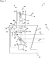
- Fig. 1 shows a schematic sectional view through a laser scanner 10.
- a light emitter 12 for example with a laser light source, generated by means of a transmitting optical system 14, a transmitted light beam 16, which is deflected via a mirror 18a at a movable deflection unit 18 in a monitoring area 20. If the transmitted light beam 16 in the monitoring area 20 is incident on an object, then remitted light 22 returns to the laser scanner 10 and is detected there via the deflection unit 18 and by means of a receiving optical unit 24 by a light receiver 26, for example a photodiode or an APD (Avalanche Photo Diode).
- APD Anavalanche Photo Diode
- the deflection unit 18 is configured in this embodiment as a rotating mirror, which rotates continuously by driving a motor 28.
- the respective angular position of the motor 28 or the deflection unit 18 is detected by an encoder, which comprises, for example, a code disk 30 and a fork light barrier 32.
- the transmitted light beam 16 generated by the light emitter 12 thus passes over the monitoring area 20 generated by the rotational movement.
- a rotating mirror it is also possible to form the deflection unit 18 as a rotating optical head in which the light emitter 12 and / or light receiver 26 and possibly further elements are housed.
- the coupling via the mirror 18a and the design of the transmitting optics 14 and the receiving optics 24 can also be varied, for example via a beam-shaping mirror as a deflection unit, a different arrangement of the lenses or additional lenses.
- laser scanners are also known in a double-eye arrangement with adjacent transmitting and receiving paths.
- the angular position of the deflection unit 18 measured by the encoder 30, 32 can be used to determine the angular position of the object in the monitoring area 20.
- the light transit time from emitting a light signal to receiving it after reflection on the object in the surveillance area 20 is detected and closed using the speed of light on the distance of the object from the laser scanner 10.
- This evaluation takes place in an evaluation unit 34, which is connected to the light emitter 12, the light receiver 26, the motor 28 and the encoder 32. Consequently Two-dimensional polar coordinates of all objects in the monitoring area 20 are available via the angle and the distance.
- the evaluation unit 34 checks whether an impermissible object intervenes in a protection area defined within the monitoring area 20. If this is the case, a safety signal 36 (OSSD, output signal switching device) outputs a safety signal to a monitored hazard source, for example a machine.
- the laser scanner 10 is in such safety applications by measures according to the standards mentioned in the introduction a safe laser scanner.
- an interface for outputting measurement data or, for example, for parameterizing the laser scanner 10 is provided instead of the safety output 36 or in addition thereto.
- a housing 38 which has a front screen 40 in the region of the light exit and light entry.
- the design of the housing 38 with a rear area without windscreen 40 is purely exemplary. In other embodiments, the windshield 40 includes the entire 360 ° viewing area.
- the evaluation unit 34 For protective field monitoring, the evaluation unit 34 must be aware of the protective field limits. Although the example of protective fields is explained below, this also applies correspondingly to other detection fields, that is to say in particular warning fields or also automation fields.
- the configuration of protective field boundaries takes place, for example, by parameterization or via software of an installation computer connected to the laser scanner 10.
- the laser scanner 10 has a projector 42, with the help of which protection fields can be projected into the monitoring area 20.
- the projector preferably has its own control unit 44, which is connected via connections 46, 48 to the evaluation unit 34.
- control unit 44 it is also conceivable to integrate the functionality of the control unit 44 into the evaluation unit 34.
- the projector 42 in the embodiment uses FIG. 1 a projecting light emitter 54 rotating by means of motor 50 and adjustable in inclination by means of tilting device 52, for example a laser light source in the visible wavelength range with a projection optics, not shown. Thereby, a visible projection light beam 56 is emitted into the surveillance area 20.
- the projection light beam 56 rotates fast enough that a continuous circle is visible in the monitoring area 20 and especially there on the ground. At the same time, the tilt is fast enough to vary the radius of the circles during the rotations and thus to draw the total number of protection fields in polar coordinates.
- the projector 42 can also be integrated into the housing 40 of the actual laser scanner, in particular with shared use of the motor 28 or even the deflection unit 18.
- the projection light transmitter 54 does not need to rotate itself to generate a rotational movement, but can also use a rotating deflection unit, both in the case of a separate plug-in device as well as in an integration in the housing 40th
- the tilt unit 52 also preferably does not generate direct movement of the projection light transmitter 54, although that is possible, but rather moves a mirror. This may be an additional mirror in the path of the projection light beam 56 or a mirror of the deflection unit. Particularly suitable are controllable micromirrors (DLP, Digital Light Processing).
- control unit 44 and the evaluation unit 34 have a direct connection via the terminals 46, 48, it is also conceivable first to read the configuration data with the protective field boundaries, for example with a USB stick to a corresponding interface on the housing 38, and then into the projector 42ndivaster.
- the configuration data can also be transmitted via a connected computer or a higher-level controller.
- control unit 44 If protective fields are to be drawn on the ground, the control unit 44 must be aware of the position of the laser scanner 10, namely its height above the ground and its inclination. Otherwise, the projection would lead to considerable distortions because a protective field is configured in practice significantly above the level of the ground.
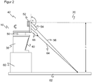
- FIG. 2 shows a schematic representation of the laser scanner 10 in an application environment. For the sake of clarity, only a small part of the elements of the laser scanner is shown, but then provided with the same reference numerals as in FIG. 1 ,
- the laser scanner 10 stands on a pedestal 60 at a certain height above the floor 62.
- the projector 42 produces the visible projection beam 56, the one point on impact with the floor 62 and in the course of superimposed rotational and tilting movement by motor 50 and tilting device 52nd the protective fields draws.
- the standards in FIG. 2 are for explanation purposes only and are rather untypical, since the laser scanner 10 is clearly mounted higher in most cases and small compared to the distance and dimensions of surveillance area 20 and protective fields.
- inclination angle ⁇ and height h above the ground 62 should be known.
- inclination sensors (not shown) may preferably be used in two axes, from which the inclination in all directions can then be derived. This inclination is then compensated for in the projection in the tilt angles of the tilting device 52.
- the height may be determined by the projector 42 in a preferred embodiment.
- the projection light transmitter 54 is tilted by means of the tilting device 52 in a calibration step in a fixed angular position, ie with the motor 50, until the projection light beam 64 reflected at the bottom 62 strikes a height measuring light receiver 66 mounted slightly below the projection light transmitter 54. Knowing the previously determined inclination of the laser scanner 10 and the internal geometry, in particular the distance between the projection light transmitter 54 and the height measuring light receiver 66, the height h can be calculated from the tilt angle required for this constellation.
- only one projection light transmitter 54 is provided in each case. It is conceivable to use several light sources of different colors, preferably with mutual angular offset. As a result, certain protective fields or parts thereof can be identified by different colors. It is also possible to display the type of a detection field, for example, to display warning fields in blue and protective fields in red or yellow.
- the projection of detection fields is particularly useful when a plurality of laser scanners 10 according to the invention are mounted together on a surveillance area. Then it is immediately apparent where all the detection fields are. By different colors that can be assigned to the involved laser scanners 10 and so the common configuration can be significantly accelerated.
- the invention is also suitable for mobile applications, for example in securing vehicles or AGVs (autonomous guided vehicle). There, it is particularly advantageous in configuration and operation when the particular speed-adapted detection fields are displayed, for example, to indicate to persons the critical area from which they must stay away.
Landscapes
- Engineering & Computer Science (AREA)
- Physics & Mathematics (AREA)
- Computer Networks & Wireless Communication (AREA)
- General Physics & Mathematics (AREA)
- Radar, Positioning & Navigation (AREA)
- Remote Sensing (AREA)
- Electromagnetism (AREA)
- Optical Radar Systems And Details Thereof (AREA)
- Length Measuring Devices By Optical Means (AREA)
Description
- Die Erfindung betrifft einen optoelektronischen Sensor, insbesondere einen Laserscanner, und ein Verfahren zum Erfassen von Objekten nach dem Oberbegriff von Anspruch 1 beziehungsweise 10.
- In einem Laserscanner überstreicht ein von einem Laser erzeugter Lichtstrahl mit Hilfe einer Ablenkeinheit periodisch einen Überwachungsbereich. Das Licht wird an Objekten in dem Überwachungsbereich remittiert und in dem Scanner ausgewertet. Aus der Winkelstellung der Ablenkeinheit wird auf die Winkellage des Objektes und aus der Lichtlaufzeit unter Verwendung der Lichtgeschwindigkeit zusätzlich auf die Entfernung des Objektes von dem Laserscanner geschlossen. Mit den Winkel- und Entfernungsangaben ist der Ort eines Objektes in dem Überwachungsbereich in zweidimensionalen Polarkoordinaten erfasst. Damit lassen sich die Positionen von Objekten ermitteln oder deren Kontur bestimmen.
- Laserscanner werden in der Sicherheitstechnik zur Überwachung einer Gefahrenquelle eingesetzt, wie sie beispielsweise eine gefährliche Maschine darstellt. Ein derartiger Sicherheitslaserscanner ist aus der
DE 43 40 756 A1 bekannt. Dabei wird ein Schutzfeld überwacht, das während des Betriebs der Maschine vom Bedienpersonal nicht betreten werden darf. Erkennt der Laserscanner einen unzulässigen Schutzfeldeingriff, etwa ein Bein einer Bedienperson, so löst er einen Nothalt der Maschine aus. Andere Eingriffe in das Schutzfeld, beispielsweise durch statische Maschinenteile, können vorab als zulässig eingelernt werden. - Sicherheitslaserscanner müssen besonders zuverlässig arbeiten und deshalb hohe Sicherheitsanforderungen erfüllen, beispielsweise die Norm EN 13849 für Maschinensicherheit und die Gerätenorm EN61496 für berührungslos wirkende Schutzeinrichtungen (BWS). Zur Erfüllung dieser Sicherheitsnormen sind eine Reihe von Maßnahmen zu treffen, wie sichere elektronische Auswertung durch redundante, diversitäre Elektronik, Funktionsüberwachung oder speziell Überwachung der Verschmutzung optischer Bauteile, insbesondere einer Frontscheibe.
- Eine Verallgemeinerung eines Schutzfeldes auch für Anwendungen außerhalb der Sicherheitstechnik, etwa für die Automatisierungstechnik, wird hier als Detektionsfeld bezeichnet. Detektionsfelder sind virtuell definierte Teilbereiche des Überwachungsbereichs des Laserscanners, die üblicherweise zur Einrichtzeit konfiguriert und zur Laufzeit ausgewertet werden. Die Detektionsfelder legen fest, welche Bereiche der erfassten Szenerie auf Objekte hin auszuwerten sind, wobei sich dies möglicherweise nur jeweils auf einen bestimmten Zeitpunkt bezieht und sich die Definition der Detektionsfelder zu einem anderen Zeitpunkt verändert. Der Typ des Detektionsfeldes bestimmt, welche Art der Auswertung vorzunehmen ist und welche Reaktion ein Objekteingriff in ein Detektionsfeld auslöst. Bei den schon angesprochenen Schutzfeldern führt ein Objekteingriff zu einer sicherheitsgerichteten Abschaltung. Warnfelder sind zumeist Schutzfeldern vorgelagert und lösen einen Alarm aus, ohne direkt in das System einzugreifen, und sollen in der Regel durch den Alarm einen weitergehenden Eingriff in ein Schutzfeld noch rechtzeitig verhindern. Automatisierungsfelder sind der allgemeine Komplementärbegriff zu Schutz- und Warnfeldern, also nicht sicherheitsrelevant, sondern werden beispielsweise in Form eines Funktionsfeldes als virtueller Schalter, als Messfeld zu Bestimmung von Volumina oder für andere Messungen genutzt.
- Das Konfigurieren von Detektionsfeldern, vor allem im Falle der sicherheitsrelevanten Schutzfelder, ist für eine ordnungsgemäße Funktion des Laserscanners wesentlich. Dennoch werden dem Benutzer derzeit relativ wenig Hilfsmittel zur Verfügung gestellt. Üblicherweise erfolgt eine Eingabe der Grenzen des Detektionsfeldes im Laserscanner oder in einer Konfigurationssoftware. Dabei müssen die Abmessungen des Detektionsfeldes bekannt sein, und es gibt kein Feedback in der tatsächlichen Szenerie außer durch mühsames Austesten mit einem Prüfstab. Es ist zwar auch bekannt, die Schutzfelder durch Klebebänder oder farbige Flächen zu kennzeichnen. Das enthebt den Benutzer aber nicht davon, dafür zu sorgen, dass in dem Laserscanner tatsächlich die so gekennzeichneten Bereiche als Detektionsfelder konfiguriert sind.
- Aus der
DE 20 2009 012 589 U1 ist unter anderem ein Laserscanner bekannt, der einen sichtbaren Lichtstrahl in Richtung eines in einem Schutzbereich erfassten Objekts aussendet. Damit wird die Überprüfung der konfigurierten Schutzfelder erleichtert, aber es ist weiterhin jeweils nur ein punktueller Test möglich und fehlt an einem Gesamtüberblick. - Die
US 2012/0057174 A1 offenbart einen Laserscanner mit einem integrierten Projektor, der dazu in der Lage ist, sichtbare Informationen auf ein in der Umgebung befindliches Objekts zu projizieren. Diese Informationen sind beispielsweise Bilder, CAD-Daten oder Punktwolken von Scannermessungen. So wird beispielsweise eine Textur über ein Objekt oder ein virtuelles Objekt in einer geplanten oder idealen Konfiguration über das tatsächliche Objekt projiziert. Es ist aber weder eine Absicherung mit Hilfe von Schutzfeldern noch eine Visualisierung von Detektionsfeldern vorgesehen. - Die
US 2005/0052720 A1 befasst sich mit einem Laserprojektionssystem, bei dem ein Laserstrahl mit Hilfe zweier zueinander senkrecht angeordneter, rotierende Ablenkspiegel in zwei Dimensionen lenkbar ist. Es gibt aber keinen Zusammenhang mit Laserscannern. - Es ist deshalb Aufgabe der Erfindung, in einem Laserscanner den Umgang mit Detektionsfeldern zu vereinfachen.
- Diese Aufgabe wird durch einen optoelektronischen Sensor, insbesondere einen Laserscanner, und ein Verfahren zum Erfassen von Objekten nach Anspruch 1 beziehungsweise 10 gelöst. Der Sensor führt einen Abtaststrahl eines Lichtsenders periodisch mit Hilfe einer beweglichen Ablenkeinheit durch den Überwachungsbereich und wertet das Empfangssignal eines Lichtempfängers aus. Die bewegliche Ablenkeinheit ist häufig ein Drehspiegel, es kann aber auch beispielsweise ein Messkopf mit Lichtsender und Lichtempfänger rotieren. Der Sensor überwacht durch Auswertung des Empfangssignals in einer Auswertungseinheit ein Detektionsfeld oder mehrere Detektionsfelder auf Objekteingriffe. Die Erfindung geht nun von dem Grundgedanken aus, die Detektionsfelder in dem Überwachungsbereich zu visualisieren. Dazu ist ein Projektor vorgesehen, der die Detektionsfelder kennt, etwa durch gemeinsamen Zugriff von Projektor und Auswertungseinheit auf einen entsprechenden Konfigurationsspeicher oder eine Daten- oder Steuerverbindung zwischen Projektor und Auswertungseinheit. Die Visualisierung kann bedeuten, dass das gesamte Detektionsfeld homogen oder mit einem Muster beleuchtet wird. Es genügt aber alternativ auch, die Außengrenzen oder nur einige markante Bereiche, wie Ecken oder ein Zentrum, durch Punkte, Fadenkreuze oder dergleichen darzustellen.
- Die Erfindung hat den Vorteil, dass das Einrichten und Kontrollieren von Detektionsfeldern erheblich erleichtert wird. Es entfällt außerdem eine wesentliche Fehlerquelle, weil sofort erkennbar ist, wo die Detektionsfelder liegen, und es deshalb keine unbemerkten Diskrepanzen zwischen den gewünschten und den tatsächlichen Detektionsfeldern geben kann. Obwohl die Visualisierung in erster Linie für eine anfängliche Konfiguration gedacht ist, kann es auch während des Betriebs nützlich sein, die Detektionsfelder dauerhaft oder auf Anforderung anzuzeigen, etwa damit Personen im Arbeitsbereich des Laserscanners versehentliche Eingriffe in das Detektionsfeld leichter vermeiden oder sich an eine neue Konfiguration gewöhnen können.
- Eine Steuereinheit des Projektors ist dafür ausgebildet, das Detektionsfeld durch Projektion auf den Boden zu visualisieren. Der Boden bietet eine gut sichtbare Projektionsfläche. So können Detektionsfelder besonders leicht an Gefahrenquellen oder Arbeitsbereiche angepasst werden.
- Die Steuereinheit ist für eine Kalibrierung ausgebildet, in der Höhe und/oder Neigung des Projektors festgestellt wird. Aus diesen Parametern kann die Steuereinheit berechnen, wie die Detektionsfelder passend aus der eigenen Perspektive auf den Boden projiziert werden. Ohne Kalibrierung müssten die Werte vorgegeben, beispielsweise parametriert werden, oder es entsteht eine Ungenauigkeit, wenn die Detektionsfelder nicht in Bodenhöhe konfiguriert sind, was praktisch immer der Fall ist.
- Der Projektor weist bevorzugt eine rotierende Lichtquelle auf. Das Projektionsverfahren ähnelt dann dem Abtastverfahren des Laserscanners. Unter einer rotierenden Lichtquelle wird sowohl eine selbst physisch bewegte Lichtquelle als auch eine Rotationsbewegung nur des Lichtstrahls mit Hilfe eines Drehspiegels verstanden. Die Lichtquelle ist vorzugsweise ein Laser im sichtbaren Wellenlängenbereich.
- Der Projektor weist bevorzugt eine Verkippeinheit zur Einstellung der Neigung der Lichtquelle auf. Dadurch ist die Projektion in Elevation veränderbar. In Kombination mit einer rotierenden Lichtquelle ergibt sich die Möglichkeit, beliebige geometrische Formen in Polarkoordinaten und damit beliebig gestaltete Detektionsfelder zu projizieren.
- Die Neigung kann durch Verkippung der Lichtquelle selbst, aber auch durch Verkippen eines nachgeordneten Spiegels, insbesondere eines Drehspiegels erreicht werden. Geeignet ist beispielsweise ein steuerbarer Mikrospiegel (DLP, Digital Light Processing).
- Der Projektor weist vorzugsweise einen Neigungssensor auf. Damit kann die Kalibrierung auf die tatsächliche Neigung jederzeit automatisch ohne Eingriff des Bedienpersonals erfolgen.
- Der Projektor weist bevorzugt einen Detektor auf, um die Höhe des Projektors zu bestimmen. So wird auch die Höhe automatisch erfassbar. Beispielsweise ist ein kleiner Detektor unterhalb der Lichtquelle des Projektors angebracht und die Höhe dann anhand des Projektionsstrahls trianguliert. Mit Neigungssensor und Detektor oder anderen Erfassungsmitteln für Neigung und Höhe ist dann insgesamt eine selbsttätige Kalibration möglich und kein händisches Einmessen erforderlich.
- Der Projektor ist vorzugsweise als Zusatzmodul ausgebildet. Beispielsweise ist der Projektor ein eigenes Aufsatzgerät. Dann sind Kalibrierflächen vorteilhaft, die Projektor und Laserscanner in eine genau definierte und bekannte Relativlage bringen. Ein Vorteil eines Zusatzgeräts ist die Möglichkeit der Nachrüstung. Außerdem kann beispielsweise nur ein Servicetechniker oder eine für die Anlage verantwortliche Person mit einem einzigen Zusatzmodul eine beliebige Anzahl von Laserscannern nacheinander konfigurieren.
- Der Projektor ist vorzugsweise in den Sensor integriert. Nochmals bevorzugt nutzt der Projektor die Ablenkeinheit des Abtaststrahls mit. Es rotiert also beispielsweise auch die Lichtquelle des Projektors in einem beweglichen Messkopf mit Lichtsender und Lichtempfänger des Abtaststrahls. Alternativ wird der sichtbare Lichtstrahl des Projektors in einem der jeweils gewünschten Neigung entsprechenden Winkel auf den Drehspiegel gekoppelt. Ein Vorteil einer integrierten Lösung ist, dass für die Drehbewegung des Projektors der ohnehin schon vorhandene Antrieb der Ablenkeinheit doppelt genutzt wird.
- Der Projektor weist bevorzugt mehrere rotierende Lichtquellen mit unterschiedlichen Wellenlängen auf. Die Lichtquellen weisen nochmals bevorzugt einen gegenseitigen Winkelversatz auf. Durch unterschiedliche Wellenlängen ergeben sich neue Darstellungsmöglichkeiten, mit denen Detektionsfelder oder Teile davon in eigenen Farben visualisiert werden können. Eine bevorzugte Ausführungsform zeigt unterschiedliche Typen von Detektionsfeldern in eigener Farbe, etwa Warnfelder in einer anderen Farbe als Schutzfelder.
- Der Sensor ist vorzugsweise als Entfernungsmesser ausgebildet, indem die Auswertungseinheit die Lichtlaufzeit zwischen Aussenden und Empfang des Lichtsignals und daraus die Entfernung eines Objekts bestimmt und/oder wobei eine Winkelmesseinheit zur Erfassung der Winkelstellung der Ablenkeinheit vorgesehen ist. Über die Entfernungs- und Winkelmessungen stehen vollständige zweidimensionale Polarkoordinaten zur Verfügung, mit denen in einem als Ebene ausgebildeten Überwachungsbereich beliebige Detektionsfelder definiert werden können. Das korrespondiert gerade mit einem Projektor, der durch Rotation und Verkippung der Lichtquelle ebenfalls beliebige geometrische Formen in Polarkoordinaten und damit sämtliche Detektionsfelder visualisieren kann.
- Der Sensor ist vorzugsweise als Sicherheitslaserscanner ausgebildet und weist einen Sicherheitsausgang (OSSD, Output Signal Switching Device) auf, wobei die Auswertungseinheit dafür ausgebildet ist zu bestimmen, ob sich ein Objekt in einem als Schutzfeld ausgebildeten Detektionsfeld innerhalb des Überwachungsbereichs befindet, um daraufhin ein sicherheitsgerichtetes Abschaltsignal über den Sicherheitsausgang auszugeben. In dieser sicherheitstechnischen Ausprägung ist die Übereinstimmung gewünschter und tatsächlicher Schutzfelder besonders kritisch und daher deren intuitive Erkennbarkeit besonders hilfreich.
- Das erfindungsgemäße Verfahren kann auf ähnliche Weise weitergebildet werden und zeigt dabei ähnliche Vorteile. Derartige vorteilhafte Merkmale sind beispielhaft, aber nicht abschließend in den sich an die unabhängigen Ansprüche anschließenden Unteransprüchen beschrieben.
- Die Erfindung wird nachstehend auch hinsichtlich weiterer Merkmale und Vorteile beispielhaft anhand von Ausführungsformen und unter Bezug auf die beigefügte Zeichnung näher erläutert. Die Abbildungen der Zeichnung zeigen in:
- Fig. 1
- eine schematische Schnittzeichnung eines erfindungsgemäßen Laserscanners; und
- Fig. 2
- eine schematische Darstellung eines Laserscanners in einer Anwendungsumgebung zur Illustration der Projektion von Detektionsfeldern.
-
Fig. 1 zeigt eine schematische Schnittdarstellung durch einen Laserscanner 10. Ein Lichtsender 12, beispielsweise mit einer Laserlichtquelle, erzeugt mit Hilfe einer Sendeoptik 14 einen Sendelichtstrahl 16, der über einen Spiegel 18a an einer beweglichen Ablenkeinheit 18 in einen Überwachungsbereich 20 umgelenkt wird. Fällt der Sendelichtstrahl 16 in dem Überwachungsbereich 20 auf ein Objekt, so gelangt remittiertes Licht 22 wieder zu dem Laserscanner 10 zurück und wird dort über die Ablenkeinheit 18 und mittels einer Empfangsoptik 24 von einem Lichtempfänger 26 detektiert, beispielsweise einer Photodiode oder einer APD (Avalanche Photo Diode). - Die Ablenkeinheit 18 ist in dieser Ausführungsform als Drehspiegel ausgestaltet, die durch Antrieb eines Motors 28 kontinuierlich rotiert. Die jeweilige Winkelstellung des Motors 28 beziehungsweise der Ablenkeinheit 18 wird über einen Encoder erkannt, der beispielsweise eine Codescheibe 30 und eine Gabellichtschranke 32 umfasst. Der von dem Lichtsender 12 erzeugte Sendelichtstrahl 16 überstreicht somit den durch die Rotationsbewegung erzeugten Überwachungsbereich 20. Anstelle eines Drehspiegels ist es auch möglich, die Ablenkeinheit 18 als rotierenden Optikkopf auszubilden, in dem Lichtsender 12 und/oder Lichtempfänger 26 und möglicherweise weitere Elemente untergebracht sind. Auch die Einkopplung über den Spiegel 18a sowie die Gestaltung von Sendeoptik 14 und Empfangsoptik 24 kann variiert werden, etwa über einen strahlformenden Spiegel als Ablenkeinheit, eine andere Anordnung der Linsen oder zusätzliche Linsen. Insbesondere sind Laserscanner auch in einer Doppelaugenanordnung mit nebeneinander liegenden Sende- und Empfangspfaden bekannt.
- Wird nun von dem Lichtempfänger 26 remittiertes Licht 22 aus dem Überwachungsbereich 20 empfangen, so kann aus der von dem Encoder 30, 32 gemessenen Winkelstellung der Ablenkeinheit 18 auf die Winkellage des Objektes in dem Überwachungsbereich 20 geschlossen werden. Zusätzlich wird vorzugsweise die Lichtlaufzeit von Aussenden eines Lichtsignals bis zu dessen Empfang nach Reflexion an dem Objekt in dem Überwachungsbereich 20 ermittelt und unter Verwendung der Lichtgeschwindigkeit auf die Entfernung des Objektes von dem Laserscanner 10 geschlossen.
- Diese Auswertung erfolgt in einer Auswerteeinheit 34, die dafür mit dem Lichtsender 12, dem Lichtempfänger 26, dem Motor 28 und dem Encoder 32 verbunden ist. Somit stehen über den Winkel und die Entfernung zweidimensionale Polarkoordinaten aller Objekte in dem Überwachungsbereich 20 zur Verfügung. In sicherheitstechnischer Anwendung prüft die Auswertungseinheit 34, ob ein unzulässiges Objekt in einen innerhalb des Überwachungsbereichs 20 festgelegten Schutzbereich eingreift. Ist das der Fall, wird über einen Sicherheitsausgang 36 (OSSD, Output Signal Switching Device) ein Absicherungssignal an eine überwachte Gefahrenquelle, beispielsweise eine Maschine ausgegeben. Der Laserscanner 10 ist in derartigen sicherheitstechnischen Anwendungen durch Maßnahmen entsprechend der einleitend genannten Normen ein sicherer Laserscanner. In andern Ausführungsformen ist anstelle des Sicherheitsausgangs 36 oder zusätzlich dazu eine Schnittstelle zur Ausgabe von Messdaten oder beispielsweise zum Parametrieren des Laserscanners 10 vorgesehen.
- Alle bisher genannten Funktionskomponenten sind in einem Gehäuse 38 angeordnet, das im Bereich des Lichtaus- und Lichteintritts eine Frontscheibe 40 aufweist. Die Gestaltung des Gehäuses 38 mit einem rückwärtigen Bereich ohne Frontscheibe 40 ist rein beispielhaft. In anderen Ausführungsformen umfasst die Frontscheibe 40 den gesamten 360°-Sichtbereich.
- Für die Schutzfeldüberwachung müssen der Auswertungseinheit 34 die Schutzfeldgrenzen bekannt sein. Obwohl im Folgenden das Beispiel von Schutzfeldern erläutert wird, gilt dies entsprechend auch für andere Detektionsfelder, also insbesondere Warnfelder oder auch Automatisierungsfelder. Die Konfiguration von Schutzfeldgrenzen erfolgt beispielweise durch Parametrierung oder über eine Software eines an den Laserscanner 10 angeschlossenen Installationsrechners.
- Um während der Installation, aber auch bei Wartungen oder im späteren Betrieb die Möglichkeit zu haben, die eingestellten Schutzfelder zu prüfen, weist der Laserscanner 10 einen Projektor 42 auf, mit dessen Hilfe Schutzfelder in den Überwachungsbereich 20 projiziert werden können. Der Projektor verfügt vorzugsweise über eine eigene Steuereinheit 44, die über Anschlüsse 46, 48 mit der Auswertungseinheit 34 in Verbindung steht. Es ist aber auch denkbar, die Funktionalität der Steuereinheit 44 in die Auswertungseinheit 34 zu integrieren.
- Obwohl prinzipiell jede Projektionstechnik möglich ist, nutzt der Projektor 42 in der Ausführungsform nach
Figur 1 einen mittels Motor 50 rotierenden und mittels Verkippungseinrichtung 52 in seiner Neigung verstellbaren Projektionslichtsender 54, beispielsweise eine Laserlichtquelle im sichtbaren Wellenlängenbereich mit einer nicht dargestellten Projektionsoptik. Dadurch wird ein sichtbarer Projektionslichtstrahl 56 in den Überwachungsbereich 20 ausgesandt. - Der Projektionslichtstrahl 56 rotiert schnell genug, dass im Überwachungsbereich 20 und insbesondere dort auf dem Boden ein durchgängiger Kreis sichtbar wird. Zugleich ist die Verkippung schnell genug, um den Radius der Kreise während der Rotationen zu variieren und so insgesamt die Schutzfelder in Polarkoordinaten zu zeichnen.
- Es sind zahlreiche Variationen des Projektors 42 möglich. In der in
Figur 1 dargestellten Ausführungsform handelt es sich um ein Aufsteckgerät in einem eigenen Gehäuse 58. Dabei sind die Verbindungsflächen der beiden Gehäuse 38, 58 wohldefiniert, um für eine genaue und bekannte Relativlage zu sorgen, in der die angezeigten und überwachten Schutzfelder übereinstimmen. Nachstellschrauben oder eine andere Ausrichthilfe über Magnete sind denkbar. Alternativ zu einem separaten Aufsteckgerät kann der Projektor 42 aber auch in das Gehäuse 40 des eigentlichen Laserscanners integriert werden, insbesondere auch unter Mitnutzung des Motors 28 oder sogar der Ablenkeinheit 18. Denn der Projektionslichtsender 54 muss zur Erzeugung einer Rotationsbewegung nicht selbst rotieren, sondern kann dafür auch eine rotierende Ablenkeinheit nutzen, und zwar sowohl im Falle eines separaten Aufsteckgeräts als auch bei einer Integration in das Gehäuse 40. - Die Verkippungseinheit 52 erzeugt vorzugsweise ebenfalls keine direkte Bewegung des Projektionslichtsenders 54, obwohl das möglich ist, sondern bewegt einen Spiegel. Das kann ein zusätzlicher Spiegel im Pfad des Projektionslichtstrahls 56 oder ein Spiegel der Ablenkeinheit sein. Besonders geeignet sind steuerbare Mikrospiegel (DLP, Digital Light Processing).
- Während in
Figur 1 die Steuereinheit 44 und die Auswertungseinheit 34 eine direkte Verbindung über die Anschlüsse 46, 48 haben, ist auch denkbar, die Konfigurationsdaten mit den Schutzfeldgrenzen zunächst auszulesen, beispielsweise mit einem USB-Stick an einer entsprechenden Schnittstelle am Gehäuse 38, und anschließend in den Projektor 42 einzuspielen. Die Konfigurationsdaten können auch über einen angeschlossenen Computer oder eine übergeordnete Steuerung übertragen werden. - Sollen Schutzfelder auf den Boden gezeichnet werden, so muss der Steuereinheit 44 die Position des Laserscanners 10, nämlich dessen Höhe über dem Boden und seine Neigung, bekannt sein. Ansonsten käme es durch die Projektion zu erheblichen Verzerrungen, weil ein Schutzfeld in der Praxis deutlich über dem Niveau des Bodens konfiguriert wird.
-
Figur 2 zeigt eine schematische Darstellung des Laserscanners 10 in einer Anwendungsumgebung. Dabei ist der Übersichtlichkeit halber nur ein kleiner Teil der Elemente des Laserscanners gezeigt, dann aber mit den gleichen Bezugszeichen versehen wie inFigur 1 . - Der Laserscanner 10 steht auf einem Sockel 60 in einer gewissen Höhe über dem Boden 62. Der Projektor 42 erzeugt den sichtbaren Projektionsstrahl 56, der bei Auftreffen auf den Boden 62 einen Punkt und im Verlauf der überlagerten Rotations- und Kippbewegung durch Motor 50 und Verkippungseinrichtung 52 die Schutzfelder zeichnet. Die Maßstäbe in
Figur 2 dienen nur der Erläuterung und sind eher untypisch, da der Laserscanner 10 deutlich meist höher montiert und klein gegenüber Entfernung und Dimensionen von Überwachungsbereich 20 und Schutzfeldern ist. - Zur Kalibration des Projektors 42 sollen Neigungswinkel α sowie Höhe h über dem Boden 62 bekannt sein. Für die Bestimmung des Neigungswinkels α können nicht dargestellte Neigungssensoren vorzugsweise in zwei Achsen verwendet werden, aus denen dann die Neigung in allen Richtungen abgeleitet werden kann. Diese Neigung wird dann bei der Projektion in den Kippwinkeln der Verkippungseinrichtung 52 kompensiert.
- Die Höhe kann der Projektor 42 in einer bevorzugten Ausführungsform selbst bestimmen. Dazu wird in einem Kalibrierungsschritt in einer festen Winkelposition, also bei ruhendem Motor 50, der Projektionslichtsender 54 mit Hilfe der Verkippungseinrichtung 52 so lange verkippt, bis der am Boden 62 remittierte Projektionslichtstrahl 64 auf einen etwas unterhalb des Projektionslichtsenders 54 angebrachten Höhenmesslichtempfänger 66 trifft. Aus dem für diese Konstellation benötigten Kippwinkel kann in Kenntnis der zuvor bestimmten Neigung des Laserscanners 10 sowie der internen Geometrie, insbesondere des Abstands zwischen Projektionslichtsender 54 und Höhenmesslichtempfänger 66, die Höhe h berechnet werden.
- In den bisher beschriebenen Ausführungsformen ist jeweils nur ein Projektionslichtsender 54 vorgesehen. Es ist denkbar, mehrere Lichtquellen unterschiedlicher Farbe vorzugsweise mit gegenseitigem Winkelversatz zu verwenden. Dadurch können bestimmte Schutzfelder oder Teile davon durch verschiedene Farben gekennzeichnet werden. Es ist auch möglich, den Typ eines Detektionsfeldes anzuzeigen, also beispielsweise Warnfelder in blau und Schutzfelder in rot oder gelb anzuzeigen.
- Die Projektion von Detektionsfeldern ist besonders nützlich, wenn mehrere erfindungsgemäße Laserscanner 10 gemeinsam an einem Überwachungsbereich montiert sind. Dann ist sofort ersichtlich, wo sämtliche Detektionsfelder liegen. Durch unterschiedliche Farben kann das den beteiligten Laserscannern 10 zugeordnet werden und so die gemeinsame Konfiguration erheblich beschleunigt werden.
- Die Erfindung eignet sich auch für mobile Anwendungen, beispielsweise bei der Absicherung von Fahrzeugen oder AGVs (Autonomous Guided Vehicle). Dort ist es in Konfiguration und Betrieb besonders vorteilhaft, wenn die insbesondere geschwindigkeitsangepassten Detektionsfelder angezeigt sind, beispielsweise um Personen den kritischen Bereich anzuzeigen, aus dem sie sich fernhalten müssen.
Claims (12)
- Optoelektronischer Sensor (10), der als Sicherheitslaserscanner ausgebildet ist, mit einem Lichtsender (12) zum Aussenden eines Abtaststrahls (16) in einen Überwachungsbereich (20), einem Lichtempfänger (26) zum Erzeugen eines Empfangssignals aus dem von Objekten in dem Überwachungsbereich (20) remittierten Abtaststrahl (22), einer beweglichen Ablenkeinheit (18) zur periodischen Ablenkung des Abtaststrahls (16, 22), um im Verlauf der Bewegung den Überwachungsbereich (20) abzutasten, einem Sicherheitsausgang (36), einer Auswertungseinheit (34), die dafür ausgebildet ist, anhand des Empfangssignals zu erkennen, ob sich Objekte in mindestens einem als Schutzfeld ausgebildeten Detektionsfeld innerhalb des Überwachungsbereichs (20) befinden, um daraufhin ein sicherheitsgerichtetes Abschaltsignal über den Sicherheitsausgang (36) auszugeben, sowie mit einem Projektor (42) zur Visualisierung von Informationen des Sensors (10) in dem Überwachungsbereich (20),
dadurch gekennzeichnet,
dass der Projektor (42) eine Steuereinheit (44) aufweist, die dafür ausgebildet ist, das Schutzfeld durch Projektion auf den Boden (62) zu zeichnen, wobei in einer Kalibration Höhe des Projektors (42) über dem Boden und/oder Neigung des Projektors (42) festgestellt werden und mit Hilfe dieser Parameter berechnet wird, wie das Schutzfeld passend aus der Perspektive des Projektors (42) auf den Boden projiziert wird, ohne dass Verzerrungen entstehen, wenn das Schutzfeld nicht in Bodenhöhe konfiguriert ist. - Sensor (10) nach Anspruch 1,
wobei der Projektor (42) eine rotierende Lichtquelle (54) aufweist. - Sensor (10) nach Anspruch 2,
wobei der Projektor (42) eine Verkippeinheit (52) zur Einstellung der Neigung der Lichtquelle (54) aufweist. - Sensor (10) nach einem der vorhergehenden Ansprüche,
wobei der Projektor (42) einen Neigungssensor aufweist. - Sensor (10) nach einem der vorhergehenden Ansprüche,
wobei der Projektor (42) einen Detektor (66) aufweist, um die Höhe des Projektors (42) zu bestimmen. - Sensor (10) nach einem der vorhergehenden Ansprüche,
wobei der Projektor (42) als Zusatzmodul ausgebildet ist. - Sensor (10) nach einem der Ansprüche 1 bis 5,
wobei der Projektor (42) in den Sensor (10) integriert ist. - Sensor (10) nach einem der vorhergehenden Ansprüche,
wobei der Projektor (42) mehrere rotierende Lichtquellen mit unterschiedlichen Wellenlängen aufweist. - Sensor (10) nach einem der vorhergehenden Ansprüche,
der als Entfernungsmesser ausgebildet ist, indem die Auswertungseinheit (34) die Lichtlaufzeit zwischen Aussenden und Empfang des Abtaststrahls (16, 22) und daraus die Entfernung eines Objekts bestimmt und/oder wobei eine Winkelmesseinheit (30, 32) zur Erfassung der Winkelstellung der Ablenkeinheit (18) vorgesehen ist. - Sicherheitstechnisches Verfahren zum Erfassen von Objekten, bei dem ein Abtaststrahl (16) in einen Überwachungsbereich (20) ausgesandt wird, aus dem von Objekten in dem Überwachungsbereich (20) remittierten Abtaststrahl (22) ein Empfangssignal erzeugt und der Abtaststrahl (16, 22) mit einer drehbaren Ablenkeinheit (18) periodisch abgelenkt wird, um im Verlauf der Bewegung den Überwachungsbereich (20) abzutasten, und durch Auswertung des Empfangssignals erkannt wird, ob sich Objekte in einem als Schutzfeld ausgebildeten Detektionsfeld innerhalb des Überwachungsbereichs (20) befindet, um daraufhin ein sicherheitsgerichtetes Abschaltsignal über einen Sicherheitsausgang (36) auszugeben, wobei mit einem Projektor (42) Informationen in dem Überwachungsbereich visualisiert werden,
dadurch gekennzeichnet,
dass eine Steuereinheit (44) des Projektors (42) das Schutzfeld durch Projektion auf den Boden (62) zeichnet, wobei in einer Kalibration Höhe des Projektors (42) über dem Boden und/oder Neigung des Projektors (42) festgestellt werden und mit Hilfe dieser Parameter berechnet wird, wie das Schutzfeld passend aus der Perspektive des Projektors (42) auf den Boden projiziert wird, ohne dass Verzerrungen entstehen, wenn das Schutzfeld nicht in Bodenhöhe konfiguriert ist. - Verfahren nach Anspruch 10,
wobei das Schutzfeld projiziert wird, indem eine sichtbare Lichtquelle (54) des Projektors (42) rotiert und entsprechend der Grenzen des Schutzfelds unter Berücksichtigung von Neigung und Höhe des Projektors (42) in ihrer Kippstellung variiert und aktiviert wird. - Verfahren nach Anspruch 11,
wobei der Projektor (42) sich selbst kalibriert, um seine Neigung und Höhe festzustellen.
Priority Applications (2)
| Application Number | Priority Date | Filing Date | Title |
|---|---|---|---|
| EP16154025.7A EP3203263B1 (de) | 2016-02-03 | 2016-02-03 | Optoelektronischer sensor und verfahren zum erfassen von objekten |
| US15/423,075 US10436901B2 (en) | 2016-02-03 | 2017-02-02 | Optoelectronic sensor and method for detecting objects |
Applications Claiming Priority (1)
| Application Number | Priority Date | Filing Date | Title |
|---|---|---|---|
| EP16154025.7A EP3203263B1 (de) | 2016-02-03 | 2016-02-03 | Optoelektronischer sensor und verfahren zum erfassen von objekten |
Publications (2)
| Publication Number | Publication Date |
|---|---|
| EP3203263A1 EP3203263A1 (de) | 2017-08-09 |
| EP3203263B1 true EP3203263B1 (de) | 2018-04-18 |
Family
ID=55299355
Family Applications (1)
| Application Number | Title | Priority Date | Filing Date |
|---|---|---|---|
| EP16154025.7A Active EP3203263B1 (de) | 2016-02-03 | 2016-02-03 | Optoelektronischer sensor und verfahren zum erfassen von objekten |
Country Status (2)
| Country | Link |
|---|---|
| US (1) | US10436901B2 (de) |
| EP (1) | EP3203263B1 (de) |
Cited By (3)
| Publication number | Priority date | Publication date | Assignee | Title |
|---|---|---|---|---|
| DE102019102466A1 (de) * | 2019-01-31 | 2020-08-06 | Endress+Hauser Conducta Gmbh+Co. Kg | Optischer Sensor |
| EP4401045A1 (de) | 2023-01-10 | 2024-07-17 | Sick Ag | Konfiguration eines 3d-sensors für eine sichere objektverfolgung |
| DE102023109335A1 (de) * | 2023-04-13 | 2024-10-17 | Pepperl+Fuchs Se | Optischer Scanner und Verfahren zum Nachweis von Objekten in einem Überwachungsbereich |
Families Citing this family (9)
| Publication number | Priority date | Publication date | Assignee | Title |
|---|---|---|---|---|
| EP3193195B1 (de) * | 2016-01-18 | 2018-07-25 | SICK Engineering GmbH | Optischer sensor |
| CN111033316B (zh) * | 2017-08-18 | 2024-04-23 | 株式会社小糸制作所 | 识别传感器及其控制方法、汽车、车辆用灯具、对象识别系统、对象的识别方法 |
| EP3450913B1 (de) * | 2017-08-30 | 2021-06-09 | Hexagon Technology Center GmbH | Überwachungsinstrument zum abtasten eines objekts und zur projektion von informationen |
| US11112529B2 (en) * | 2018-08-27 | 2021-09-07 | Syncmold Enterprise Corp. | Detecting system and detecting method |
| DE102018216705A1 (de) * | 2018-09-28 | 2020-04-02 | Ibeo Automotive Systems GmbH | LIDAR-Messsystem sowie Verfahren für ein LIDAR-Messsystem |
| JP2020165930A (ja) * | 2019-03-29 | 2020-10-08 | Idec株式会社 | 表示機能付き検出装置および表示・検出システム |
| DE102019112300A1 (de) * | 2019-05-10 | 2020-11-12 | Sick Ag | Bestimmung der Entfernung eines Objekts |
| US11972612B2 (en) * | 2021-02-18 | 2024-04-30 | Fca Us Llc | Techniques to automatically verify object detection, classification, and depth for automated driving systems |
| JP7788301B2 (ja) * | 2022-02-10 | 2025-12-18 | 株式会社小糸製作所 | LiDAR装置 |
Family Cites Families (12)
| Publication number | Priority date | Publication date | Assignee | Title |
|---|---|---|---|---|
| DE4340756C5 (de) | 1992-12-08 | 2006-08-10 | Sick Ag | Laserabstandsermittlungsvorrichtung |
| JP3706203B2 (ja) * | 1996-07-22 | 2005-10-12 | 株式会社トプコン | 回転レーザ装置 |
| US20050052720A1 (en) | 2003-09-08 | 2005-03-10 | Kenneth Tetterington | Two-dimensional laser projection system |
| US9002511B1 (en) * | 2005-10-21 | 2015-04-07 | Irobot Corporation | Methods and systems for obstacle detection using structured light |
| DE202009012589U1 (de) | 2009-09-16 | 2011-02-03 | Sick Ag | Optoelektronischer Sensor |
| EP2558886B1 (de) * | 2010-04-16 | 2014-03-05 | Fraunhofer-Gesellschaft zur Förderung der angewandten Forschung e.V. | Einrichtung zur überwachung mindestens eines dreidimensionalen sicherheitsbereichs |
| CN103003713B (zh) * | 2010-09-08 | 2015-04-01 | 法罗技术股份有限公司 | 具有投影器的激光扫描器或激光跟踪器 |
| EP2530485A1 (de) * | 2011-05-31 | 2012-12-05 | Pepperl & Fuchs GmbH | Optischer Sensor zum Nachweis von Objekten und Verfahren zum optischen Anzeigen von Informationen |
| US20130241761A1 (en) * | 2012-03-16 | 2013-09-19 | Nikon Corporation | Beam steering for laser radar and other uses |
| US9282301B1 (en) * | 2012-07-25 | 2016-03-08 | Rawles Llc | System for image projection |
| US9840003B2 (en) * | 2015-06-24 | 2017-12-12 | Brain Corporation | Apparatus and methods for safe navigation of robotic devices |
| US10486742B2 (en) * | 2016-08-01 | 2019-11-26 | Magna Electronics Inc. | Parking assist system using light projections |
-
2016
- 2016-02-03 EP EP16154025.7A patent/EP3203263B1/de active Active
-
2017
- 2017-02-02 US US15/423,075 patent/US10436901B2/en active Active
Non-Patent Citations (1)
| Title |
|---|
| None * |
Cited By (4)
| Publication number | Priority date | Publication date | Assignee | Title |
|---|---|---|---|---|
| DE102019102466A1 (de) * | 2019-01-31 | 2020-08-06 | Endress+Hauser Conducta Gmbh+Co. Kg | Optischer Sensor |
| EP4401045A1 (de) | 2023-01-10 | 2024-07-17 | Sick Ag | Konfiguration eines 3d-sensors für eine sichere objektverfolgung |
| US12469174B2 (en) | 2023-01-10 | 2025-11-11 | Sick Ag | Configuration of a 3D sensor for safe object tracking |
| DE102023109335A1 (de) * | 2023-04-13 | 2024-10-17 | Pepperl+Fuchs Se | Optischer Scanner und Verfahren zum Nachweis von Objekten in einem Überwachungsbereich |
Also Published As
| Publication number | Publication date |
|---|---|
| EP3203263A1 (de) | 2017-08-09 |
| US10436901B2 (en) | 2019-10-08 |
| US20170219706A1 (en) | 2017-08-03 |
Similar Documents
| Publication | Publication Date | Title |
|---|---|---|
| EP3203263B1 (de) | Optoelektronischer sensor und verfahren zum erfassen von objekten | |
| EP3260885B1 (de) | Optoelektronischer sensor und verfahren zur erfassung von objekten | |
| EP3819671B1 (de) | Optoelektronischer sensor und verfahren zur erfassung von objekten | |
| EP2827173B1 (de) | Optoelektronischer Sensor und Verfahren zur Erfassung von Objekten | |
| EP2950115B1 (de) | Optoelektronischer sensor und verfahren zur erfassung von objekten | |
| EP2461181B1 (de) | Sensoranordnung zur Objekterkennung | |
| EP3078985B1 (de) | Optoelektronischer sensor und verfahren zur transmissionsüberwachung einer frontscheibe | |
| EP2937715B1 (de) | Optoelektronischer Sensor und Verfahren zur Erfassung von Messinformationen aus einem Überwachungsbereich | |
| EP2202533A1 (de) | Erfassungsvorrichtung | |
| EP2645125B1 (de) | Laserscanner und Verfahren zur Erfassung von Objekten in einem Überwachungsbereich | |
| EP3862780B1 (de) | Sicherheitslaserscanner und verfahren zur frontscheibenüberwachung | |
| EP3330741B1 (de) | Optoelektronischer sensor und verfahren zur erfassung von objekten in einem erfassungsbereich | |
| EP3012663A1 (de) | Sicherheitssystem zur absicherung der umgebung eines objekts | |
| EP3671264A1 (de) | Sensor und verfahren zur erfassung eines objekts | |
| EP4086661A1 (de) | Optoelektronischer sensor und verfahren zur überwachung einer frontscheibe | |
| DE202009012589U1 (de) | Optoelektronischer Sensor | |
| DE102015106837B4 (de) | Verfahren zur Steuerung einer 3D-Messvorrichtung mittels Gesten und Vorrichtung hierzu | |
| EP4067939B1 (de) | Optoelektronischer sensor | |
| EP3933433B1 (de) | Sensorvorrichtung und ausrichtverfahren | |
| EP3578868A1 (de) | Sensorsystem mit optoelektronischen distanzsensormodulen | |
| DE202014101940U1 (de) | Optoelektronischer Sensor zur Erfassung von Messinformationen aus einem Überwachungsbereich | |
| DE202013103233U1 (de) | Optoelektronischer Sensor zur Erfassung von Objekten | |
| DE102018115176B3 (de) | Stereokamera und Verfahren zum Ausrichten | |
| DE102017103791B4 (de) | Optoelektronischer Sensor und Verfahren zur Erfassung von Objekten | |
| EP1959271A1 (de) | Optoelektronische Sensoranordnung und Verfahren zur Überprüfung der Funktionsweise und/oder Justierung einer optoelektronischen Sensoranordnung |
Legal Events
| Date | Code | Title | Description |
|---|---|---|---|
| PUAI | Public reference made under article 153(3) epc to a published international application that has entered the european phase |
Free format text: ORIGINAL CODE: 0009012 |
|
| STAA | Information on the status of an ep patent application or granted ep patent |
Free format text: STATUS: EXAMINATION IS IN PROGRESS |
|
| 17P | Request for examination filed |
Effective date: 20160729 |
|
| AK | Designated contracting states |
Kind code of ref document: A1 Designated state(s): AL AT BE BG CH CY CZ DE DK EE ES FI FR GB GR HR HU IE IS IT LI LT LU LV MC MK MT NL NO PL PT RO RS SE SI SK SM TR |
|
| AX | Request for extension of the european patent |
Extension state: BA ME |
|
| GRAP | Despatch of communication of intention to grant a patent |
Free format text: ORIGINAL CODE: EPIDOSNIGR1 |
|
| STAA | Information on the status of an ep patent application or granted ep patent |
Free format text: STATUS: GRANT OF PATENT IS INTENDED |
|
| INTG | Intention to grant announced |
Effective date: 20171206 |
|
| GRAS | Grant fee paid |
Free format text: ORIGINAL CODE: EPIDOSNIGR3 |
|
| GRAA | (expected) grant |
Free format text: ORIGINAL CODE: 0009210 |
|
| STAA | Information on the status of an ep patent application or granted ep patent |
Free format text: STATUS: THE PATENT HAS BEEN GRANTED |
|
| AK | Designated contracting states |
Kind code of ref document: B1 Designated state(s): AL AT BE BG CH CY CZ DE DK EE ES FI FR GB GR HR HU IE IS IT LI LT LU LV MC MK MT NL NO PL PT RO RS SE SI SK SM TR |
|
| REG | Reference to a national code |
Ref country code: GB Ref legal event code: FG4D Free format text: NOT ENGLISH |
|
| REG | Reference to a national code |
Ref country code: CH Ref legal event code: EP |
|
| REG | Reference to a national code |
Ref country code: AT Ref legal event code: REF Ref document number: 991076 Country of ref document: AT Kind code of ref document: T Effective date: 20180515 |
|
| REG | Reference to a national code |
Ref country code: IE Ref legal event code: FG4D Free format text: LANGUAGE OF EP DOCUMENT: GERMAN |
|
| REG | Reference to a national code |
Ref country code: DE Ref legal event code: R096 Ref document number: 502016000863 Country of ref document: DE |
|
| REG | Reference to a national code |
Ref country code: NL Ref legal event code: MP Effective date: 20180418 |
|
| REG | Reference to a national code |
Ref country code: LT Ref legal event code: MG4D |
|
| PG25 | Lapsed in a contracting state [announced via postgrant information from national office to epo] |
Ref country code: NL Free format text: LAPSE BECAUSE OF FAILURE TO SUBMIT A TRANSLATION OF THE DESCRIPTION OR TO PAY THE FEE WITHIN THE PRESCRIBED TIME-LIMIT Effective date: 20180418 |
|
| PG25 | Lapsed in a contracting state [announced via postgrant information from national office to epo] |
Ref country code: AL Free format text: LAPSE BECAUSE OF FAILURE TO SUBMIT A TRANSLATION OF THE DESCRIPTION OR TO PAY THE FEE WITHIN THE PRESCRIBED TIME-LIMIT Effective date: 20180418 Ref country code: ES Free format text: LAPSE BECAUSE OF FAILURE TO SUBMIT A TRANSLATION OF THE DESCRIPTION OR TO PAY THE FEE WITHIN THE PRESCRIBED TIME-LIMIT Effective date: 20180418 Ref country code: SE Free format text: LAPSE BECAUSE OF FAILURE TO SUBMIT A TRANSLATION OF THE DESCRIPTION OR TO PAY THE FEE WITHIN THE PRESCRIBED TIME-LIMIT Effective date: 20180418 Ref country code: NO Free format text: LAPSE BECAUSE OF FAILURE TO SUBMIT A TRANSLATION OF THE DESCRIPTION OR TO PAY THE FEE WITHIN THE PRESCRIBED TIME-LIMIT Effective date: 20180718 Ref country code: PL Free format text: LAPSE BECAUSE OF FAILURE TO SUBMIT A TRANSLATION OF THE DESCRIPTION OR TO PAY THE FEE WITHIN THE PRESCRIBED TIME-LIMIT Effective date: 20180418 Ref country code: LT Free format text: LAPSE BECAUSE OF FAILURE TO SUBMIT A TRANSLATION OF THE DESCRIPTION OR TO PAY THE FEE WITHIN THE PRESCRIBED TIME-LIMIT Effective date: 20180418 Ref country code: FI Free format text: LAPSE BECAUSE OF FAILURE TO SUBMIT A TRANSLATION OF THE DESCRIPTION OR TO PAY THE FEE WITHIN THE PRESCRIBED TIME-LIMIT Effective date: 20180418 Ref country code: BG Free format text: LAPSE BECAUSE OF FAILURE TO SUBMIT A TRANSLATION OF THE DESCRIPTION OR TO PAY THE FEE WITHIN THE PRESCRIBED TIME-LIMIT Effective date: 20180718 |
|
| PG25 | Lapsed in a contracting state [announced via postgrant information from national office to epo] |
Ref country code: RS Free format text: LAPSE BECAUSE OF FAILURE TO SUBMIT A TRANSLATION OF THE DESCRIPTION OR TO PAY THE FEE WITHIN THE PRESCRIBED TIME-LIMIT Effective date: 20180418 Ref country code: LV Free format text: LAPSE BECAUSE OF FAILURE TO SUBMIT A TRANSLATION OF THE DESCRIPTION OR TO PAY THE FEE WITHIN THE PRESCRIBED TIME-LIMIT Effective date: 20180418 Ref country code: HR Free format text: LAPSE BECAUSE OF FAILURE TO SUBMIT A TRANSLATION OF THE DESCRIPTION OR TO PAY THE FEE WITHIN THE PRESCRIBED TIME-LIMIT Effective date: 20180418 Ref country code: GR Free format text: LAPSE BECAUSE OF FAILURE TO SUBMIT A TRANSLATION OF THE DESCRIPTION OR TO PAY THE FEE WITHIN THE PRESCRIBED TIME-LIMIT Effective date: 20180719 |
|
| PG25 | Lapsed in a contracting state [announced via postgrant information from national office to epo] |
Ref country code: PT Free format text: LAPSE BECAUSE OF FAILURE TO SUBMIT A TRANSLATION OF THE DESCRIPTION OR TO PAY THE FEE WITHIN THE PRESCRIBED TIME-LIMIT Effective date: 20180820 |
|
| REG | Reference to a national code |
Ref country code: DE Ref legal event code: R097 Ref document number: 502016000863 Country of ref document: DE |
|
| PG25 | Lapsed in a contracting state [announced via postgrant information from national office to epo] |
Ref country code: RO Free format text: LAPSE BECAUSE OF FAILURE TO SUBMIT A TRANSLATION OF THE DESCRIPTION OR TO PAY THE FEE WITHIN THE PRESCRIBED TIME-LIMIT Effective date: 20180418 Ref country code: CZ Free format text: LAPSE BECAUSE OF FAILURE TO SUBMIT A TRANSLATION OF THE DESCRIPTION OR TO PAY THE FEE WITHIN THE PRESCRIBED TIME-LIMIT Effective date: 20180418 Ref country code: SK Free format text: LAPSE BECAUSE OF FAILURE TO SUBMIT A TRANSLATION OF THE DESCRIPTION OR TO PAY THE FEE WITHIN THE PRESCRIBED TIME-LIMIT Effective date: 20180418 Ref country code: EE Free format text: LAPSE BECAUSE OF FAILURE TO SUBMIT A TRANSLATION OF THE DESCRIPTION OR TO PAY THE FEE WITHIN THE PRESCRIBED TIME-LIMIT Effective date: 20180418 Ref country code: DK Free format text: LAPSE BECAUSE OF FAILURE TO SUBMIT A TRANSLATION OF THE DESCRIPTION OR TO PAY THE FEE WITHIN THE PRESCRIBED TIME-LIMIT Effective date: 20180418 |
|
| PLBE | No opposition filed within time limit |
Free format text: ORIGINAL CODE: 0009261 |
|
| STAA | Information on the status of an ep patent application or granted ep patent |
Free format text: STATUS: NO OPPOSITION FILED WITHIN TIME LIMIT |
|
| PG25 | Lapsed in a contracting state [announced via postgrant information from national office to epo] |
Ref country code: SM Free format text: LAPSE BECAUSE OF FAILURE TO SUBMIT A TRANSLATION OF THE DESCRIPTION OR TO PAY THE FEE WITHIN THE PRESCRIBED TIME-LIMIT Effective date: 20180418 |
|
| 26N | No opposition filed |
Effective date: 20190121 |
|
| PGFP | Annual fee paid to national office [announced via postgrant information from national office to epo] |
Ref country code: NL Payment date: 20181221 Year of fee payment: 4 |
|
| PG25 | Lapsed in a contracting state [announced via postgrant information from national office to epo] |
Ref country code: MC Free format text: LAPSE BECAUSE OF FAILURE TO SUBMIT A TRANSLATION OF THE DESCRIPTION OR TO PAY THE FEE WITHIN THE PRESCRIBED TIME-LIMIT Effective date: 20180418 Ref country code: LU Free format text: LAPSE BECAUSE OF NON-PAYMENT OF DUE FEES Effective date: 20190203 |
|
| REG | Reference to a national code |
Ref country code: BE Ref legal event code: MM Effective date: 20190228 |
|
| REG | Reference to a national code |
Ref country code: IE Ref legal event code: MM4A |
|
| PG25 | Lapsed in a contracting state [announced via postgrant information from national office to epo] |
Ref country code: IE Free format text: LAPSE BECAUSE OF NON-PAYMENT OF DUE FEES Effective date: 20190203 |
|
| PG25 | Lapsed in a contracting state [announced via postgrant information from national office to epo] |
Ref country code: BE Free format text: LAPSE BECAUSE OF NON-PAYMENT OF DUE FEES Effective date: 20190228 |
|
| PG25 | Lapsed in a contracting state [announced via postgrant information from national office to epo] |
Ref country code: TR Free format text: LAPSE BECAUSE OF FAILURE TO SUBMIT A TRANSLATION OF THE DESCRIPTION OR TO PAY THE FEE WITHIN THE PRESCRIBED TIME-LIMIT Effective date: 20180418 |
|
| PG25 | Lapsed in a contracting state [announced via postgrant information from national office to epo] |
Ref country code: MT Free format text: LAPSE BECAUSE OF FAILURE TO SUBMIT A TRANSLATION OF THE DESCRIPTION OR TO PAY THE FEE WITHIN THE PRESCRIBED TIME-LIMIT Effective date: 20180418 |
|
| REG | Reference to a national code |
Ref country code: CH Ref legal event code: PL |
|
| GBPC | Gb: european patent ceased through non-payment of renewal fee |
Effective date: 20200203 |
|
| PG25 | Lapsed in a contracting state [announced via postgrant information from national office to epo] |
Ref country code: LI Free format text: LAPSE BECAUSE OF NON-PAYMENT OF DUE FEES Effective date: 20200229 Ref country code: CH Free format text: LAPSE BECAUSE OF NON-PAYMENT OF DUE FEES Effective date: 20200229 |
|
| PG25 | Lapsed in a contracting state [announced via postgrant information from national office to epo] |
Ref country code: GB Free format text: LAPSE BECAUSE OF NON-PAYMENT OF DUE FEES Effective date: 20200203 |
|
| PG25 | Lapsed in a contracting state [announced via postgrant information from national office to epo] |
Ref country code: CY Free format text: LAPSE BECAUSE OF FAILURE TO SUBMIT A TRANSLATION OF THE DESCRIPTION OR TO PAY THE FEE WITHIN THE PRESCRIBED TIME-LIMIT Effective date: 20180418 |
|
| PG25 | Lapsed in a contracting state [announced via postgrant information from national office to epo] |
Ref country code: IS Free format text: LAPSE BECAUSE OF FAILURE TO SUBMIT A TRANSLATION OF THE DESCRIPTION OR TO PAY THE FEE WITHIN THE PRESCRIBED TIME-LIMIT Effective date: 20180818 |
|
| PG25 | Lapsed in a contracting state [announced via postgrant information from national office to epo] |
Ref country code: HU Free format text: LAPSE BECAUSE OF FAILURE TO SUBMIT A TRANSLATION OF THE DESCRIPTION OR TO PAY THE FEE WITHIN THE PRESCRIBED TIME-LIMIT; INVALID AB INITIO Effective date: 20160203 |
|
| PG25 | Lapsed in a contracting state [announced via postgrant information from national office to epo] |
Ref country code: SI Free format text: LAPSE BECAUSE OF FAILURE TO SUBMIT A TRANSLATION OF THE DESCRIPTION OR TO PAY THE FEE WITHIN THE PRESCRIBED TIME-LIMIT Effective date: 20180418 |
|
| PG25 | Lapsed in a contracting state [announced via postgrant information from national office to epo] |
Ref country code: MK Free format text: LAPSE BECAUSE OF FAILURE TO SUBMIT A TRANSLATION OF THE DESCRIPTION OR TO PAY THE FEE WITHIN THE PRESCRIBED TIME-LIMIT Effective date: 20180418 |
|
| PGFP | Annual fee paid to national office [announced via postgrant information from national office to epo] |
Ref country code: DE Payment date: 20250218 Year of fee payment: 10 |
|
| PGFP | Annual fee paid to national office [announced via postgrant information from national office to epo] |
Ref country code: AT Payment date: 20250217 Year of fee payment: 10 |
|
| PGFP | Annual fee paid to national office [announced via postgrant information from national office to epo] |
Ref country code: FR Payment date: 20250220 Year of fee payment: 10 |
|
| PGFP | Annual fee paid to national office [announced via postgrant information from national office to epo] |
Ref country code: IT Payment date: 20250228 Year of fee payment: 10 |