EP3889646B1 - Fahrzeuginternes objektidentifizierungssystem, kraftfahrzeug, fahrzeuglampe, klassifikatorlernverfahren und rechenoperationsvorrichtung - Google Patents
Fahrzeuginternes objektidentifizierungssystem, kraftfahrzeug, fahrzeuglampe, klassifikatorlernverfahren und rechenoperationsvorrichtung Download PDFInfo
- Publication number
- EP3889646B1 EP3889646B1 EP19890797.4A EP19890797A EP3889646B1 EP 3889646 B1 EP3889646 B1 EP 3889646B1 EP 19890797 A EP19890797 A EP 19890797A EP 3889646 B1 EP3889646 B1 EP 3889646B1
- Authority
- EP
- European Patent Office
- Prior art keywords
- distance sensor
- structured
- point cloud
- identification system
- cloud data
- Prior art date
- Legal status (The legal status is an assumption and is not a legal conclusion. Google has not performed a legal analysis and makes no representation as to the accuracy of the status listed.)
- Active
Links
Images


Classifications
-
- G—PHYSICS
- G01—MEASURING; TESTING
- G01S—RADIO DIRECTION-FINDING; RADIO NAVIGATION; DETERMINING DISTANCE OR VELOCITY BY USE OF RADIO WAVES; LOCATING OR PRESENCE-DETECTING BY USE OF THE REFLECTION OR RERADIATION OF RADIO WAVES; ANALOGOUS ARRANGEMENTS USING OTHER WAVES
- G01S17/00—Systems using the reflection or reradiation of electromagnetic waves other than radio waves, e.g. lidar systems
- G01S17/88—Lidar systems specially adapted for specific applications
- G01S17/93—Lidar systems specially adapted for specific applications for anti-collision purposes
- G01S17/931—Lidar systems specially adapted for specific applications for anti-collision purposes of land vehicles
-
- G—PHYSICS
- G01—MEASURING; TESTING
- G01S—RADIO DIRECTION-FINDING; RADIO NAVIGATION; DETERMINING DISTANCE OR VELOCITY BY USE OF RADIO WAVES; LOCATING OR PRESENCE-DETECTING BY USE OF THE REFLECTION OR RERADIATION OF RADIO WAVES; ANALOGOUS ARRANGEMENTS USING OTHER WAVES
- G01S17/00—Systems using the reflection or reradiation of electromagnetic waves other than radio waves, e.g. lidar systems
- G01S17/88—Lidar systems specially adapted for specific applications
- G01S17/89—Lidar systems specially adapted for specific applications for mapping or imaging
-
- G—PHYSICS
- G01—MEASURING; TESTING
- G01S—RADIO DIRECTION-FINDING; RADIO NAVIGATION; DETERMINING DISTANCE OR VELOCITY BY USE OF RADIO WAVES; LOCATING OR PRESENCE-DETECTING BY USE OF THE REFLECTION OR RERADIATION OF RADIO WAVES; ANALOGOUS ARRANGEMENTS USING OTHER WAVES
- G01S7/00—Details of systems according to groups G01S13/00, G01S15/00, G01S17/00
- G01S7/48—Details of systems according to groups G01S13/00, G01S15/00, G01S17/00 of systems according to group G01S17/00
- G01S7/4802—Details of systems according to groups G01S13/00, G01S15/00, G01S17/00 of systems according to group G01S17/00 using analysis of echo signal for target characterisation; Target signature; Target cross-section
-
- G—PHYSICS
- G01—MEASURING; TESTING
- G01S—RADIO DIRECTION-FINDING; RADIO NAVIGATION; DETERMINING DISTANCE OR VELOCITY BY USE OF RADIO WAVES; LOCATING OR PRESENCE-DETECTING BY USE OF THE REFLECTION OR RERADIATION OF RADIO WAVES; ANALOGOUS ARRANGEMENTS USING OTHER WAVES
- G01S7/00—Details of systems according to groups G01S13/00, G01S15/00, G01S17/00
- G01S7/48—Details of systems according to groups G01S13/00, G01S15/00, G01S17/00 of systems according to group G01S17/00
- G01S7/481—Constructional features, e.g. arrangements of optical elements
- G01S7/4817—Constructional features, e.g. arrangements of optical elements relating to scanning
-
- G—PHYSICS
- G06—COMPUTING OR CALCULATING; COUNTING
- G06F—ELECTRIC DIGITAL DATA PROCESSING
- G06F18/00—Pattern recognition
- G06F18/20—Analysing
- G06F18/21—Design or setup of recognition systems or techniques; Extraction of features in feature space; Blind source separation
- G06F18/214—Generating training patterns; Bootstrap methods, e.g. bagging or boosting
-
- G—PHYSICS
- G06—COMPUTING OR CALCULATING; COUNTING
- G06F—ELECTRIC DIGITAL DATA PROCESSING
- G06F18/00—Pattern recognition
- G06F18/20—Analysing
- G06F18/24—Classification techniques
-
- G—PHYSICS
- G06—COMPUTING OR CALCULATING; COUNTING
- G06N—COMPUTING ARRANGEMENTS BASED ON SPECIFIC COMPUTATIONAL MODELS
- G06N3/00—Computing arrangements based on biological models
- G06N3/02—Neural networks
-
- G—PHYSICS
- G06—COMPUTING OR CALCULATING; COUNTING
- G06N—COMPUTING ARRANGEMENTS BASED ON SPECIFIC COMPUTATIONAL MODELS
- G06N3/00—Computing arrangements based on biological models
- G06N3/02—Neural networks
- G06N3/04—Architecture, e.g. interconnection topology
- G06N3/0499—Feedforward networks
-
- G—PHYSICS
- G06—COMPUTING OR CALCULATING; COUNTING
- G06N—COMPUTING ARRANGEMENTS BASED ON SPECIFIC COMPUTATIONAL MODELS
- G06N3/00—Computing arrangements based on biological models
- G06N3/02—Neural networks
- G06N3/08—Learning methods
- G06N3/09—Supervised learning
-
- G—PHYSICS
- G06—COMPUTING OR CALCULATING; COUNTING
- G06V—IMAGE OR VIDEO RECOGNITION OR UNDERSTANDING
- G06V20/00—Scenes; Scene-specific elements
- G06V20/50—Context or environment of the image
- G06V20/56—Context or environment of the image exterior to a vehicle by using sensors mounted on the vehicle
- G06V20/58—Recognition of moving objects or obstacles, e.g. vehicles or pedestrians; Recognition of traffic objects, e.g. traffic signs, traffic lights or roads
-
- G—PHYSICS
- G08—SIGNALLING
- G08G—TRAFFIC CONTROL SYSTEMS
- G08G1/00—Traffic control systems for road vehicles
- G08G1/01—Detecting movement of traffic to be counted or controlled
- G08G1/015—Detecting movement of traffic to be counted or controlled with provision for distinguishing between two or more types of vehicles, e.g. between motor-cars and cycles
-
- G—PHYSICS
- G06—COMPUTING OR CALCULATING; COUNTING
- G06N—COMPUTING ARRANGEMENTS BASED ON SPECIFIC COMPUTATIONAL MODELS
- G06N3/00—Computing arrangements based on biological models
- G06N3/02—Neural networks
- G06N3/08—Learning methods
Definitions
- the present invention relates to an object identification system.
- LiDAR Light Detection and Ranging
- Laser Imaging Detection and Ranging LiDAR
- advantages include: (i) an advantage of being capable of identifying an object based on point group data; (ii) an advantage in employing active sensing of providing high-precision detection even in bad weather conditions; (iii) an advantage of providing wide-range measurement; etc. Accordingly, LiDAR is anticipated to become mainstream in vehicle sensing systems.
- the precision of object identification based on the point group data generated by the LiDAR increases according to an increase in the resolution of the point group data. However, this involves a drastic increase in calculation costs.
- the present invention has been made in view of such a situation. Accordingly, it is an exemplary purpose of an embodiment of the present invention to provide a system, apparatus, and method that are capable of identifying an object using only a small number of horizontal lines.
- an object can be identified based on point cloud data that corresponds to a single scan line. Furthermore, this allows improvement in the efficiency of machine learning.
- the vehicular object identification system includes: a distance sensor structured to scan a single beam in the horizontal direction so as to measure the distances to points on the surface of an object; and a processing device including a classifier structured to be capable of identifying the kind of the object based on point cloud data that corresponds to a single scan line acquired by the distance sensor.
- the classifier is implemented based on a learned model generated by machine learning.
- the machine learning is executed using multiple items of point cloud data that correspond to multiple scan lines obtained by measuring a predetermined object by means of a LiDAR (Light Detection and Ranging) including the multiple scan lines in the vertical direction.
- LiDAR Light Detection and Ranging
- the multiple scan lines are each associated with the single scan line of the distance sensor so as to provide the training data, thereby providing improvement in the efficiency of data acquisition.
- the point cloud data that corresponds to the scan lines arranged at different heights is employed as the training data. This allows an object to be identified independent of the height of an emitted beam from the distance sensor.
- the distance sensor may include: a light source; a scanning device including a motor and a mirror attached to the motor and structured to reflect emitted light of the light source, in which the scanning device is structured such that probe light, which is light reflected by the mirror, can be scanned according to the rotation of the motor; a photosensor structured to detect return light, which is the probe light reflected from a point on an object; and a processor structured to detect the distance to the point on the object based on the output of the photosensor.
- the scanning device is configured as a combination of a commonplace motor and mirrors arranged in a fan structure. This provides the distance sensor with a lower cost.
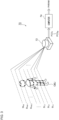
- the object identification system 10 mainly includes a distance sensor 20 and a processing device 40.
- the distance sensor 20 scans a single beam in the horizontal direction so as to measure the distances to points P on the surface of the object OBJ.
- the distance sensor 20 generates a single item of point group data PCD that corresponds to a single scan line SL.
- Each item of point cloud data PCD includes the distance information to multiple sampling points P along the scan line SL.
- the distance sensor 20 is not restricted in particular. However, in a case in which there is a need to identify an object with small irregularities, such as a pedestrian, with high precision, a LiDAR is preferably employed. It should be noted that typical LiDARs support multiple scan lines in the vertical direction. In contrast, the object identification system 10 according to the present embodiment supports only a single scan line.
- the processing device 40 outputs output data OUT that indicates the kind of the object OBJ.
- the output data OUT may indicate the probability with which the object OBJ included in the point cloud data PCD matches each of multiple categories.
- Examples of such kinds (categories) of the object include a pedestrian, bicycle, automobile, utility pole, etc.
- a pedestrian as viewed from the front, a pedestrian as viewed from the rear, and a pedestrian as viewed from the side may be classified and defined as the same kind of object. The same can be said of an automobile and a bicycle. In the present embodiment, this definition is employed.
- Fig. 2 is a block diagram showing an example configuration of the classifier 42.
- the classifier 42 may be configured employing a neural network NN.
- the neural network NN is configured including an input layer 50, three intermediate layers (hidden layers) 52, and an output layer 54.
- extraction, shifting, and normalization are preferably performed.
- Extraction is processing for removing the background so as to extract the object OBJ.
- Shifting is data shifting processing for shifting the object such that it is positioned at the center.
- Normalization is processing for dividing the distance data by a predetermined value. For example, as the predetermined value, the distance (reference distance) between the distance sensor 20 and a predetermined portion of the object OBJ at the time of the learning may be employed. This processing normalizes the value of the point cloud data such that it becomes a value in the vicinity of 1.
- the above is the basic configuration of the object identification system 10.
- the kind of the object OBJ can be judged using a single scan line.
- the number of scan lines becomes larger, the amount of calculation performed by the processing device becomes enormous.
- Such an arrangement requires a high-speed processor.
- this arrangement requires processing for only a single scan line of point cloud data, thereby allowing the amount of calculation to be reduced.
- the processing device 40 can be configured as a low-cost microcontroller. This allows the object identification system 10 to be provided with a lower cost.
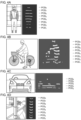
- Fig. 3 is a block diagram showing a learning system according to an embodiment.
- a learning system 70 includes a LiDAR 72 and a computer 74.
- a LiDAR (Light Detection and Ranging) 72 that supports multiple scan lines SL 1 through SL N in the vertical direction is used.
- Fig. 3 shows an example in which there is a pedestrian (human) as the object OBJ.
- the LiDAR 72 generates multiple items of point cloud data PCD 1 through PCD N that correspond to the multiple scan lines.
- the number of lines N supported by the LiDAR to be employed for the learning is preferably on the order of eight.
- Fig. 3 shows an example in which the pedestrian and the LiDAR 72 are positioned such that they face each other. However, it is preferable to acquire multiple items of point cloud data PCD 1 through PCD N for the pedestrian from multiple different directions while changing the orientation of the pedestrian.
- the multiple items of point cloud data PCD 1 through PCD N are input to the computer 74.
- the computer 74 performs machine learning with the multiple items of point cloud data PCD 1 through PCD N as the training data so as to allow a given object (a pedestrian in this example) to be identified.
- the object identification system 10 shown in Fig. 1 is capable of judging the kind of the object based on the point cloud data that corresponds to a single scan line.
- point cloud data PCD 1 through PCD N that correspond to the multiple scan lines SL 1 through SL N are not necessarily required to be used as the training data. Also, only a part of the point cloud data, which corresponds to the multiple scan lines except for both ends of the scan lines (or except for the top scan line or bottom scan line) may be employed as the training data.
- multiple sets of point cloud data may preferably be acquired by means of the LiDAR 72 while changing the kind of the object OBJ.
- the classifier 42 of the object identification system 10 is implemented based on a learned model (trained model) generated by machine learning.
- Figs. 4A through 4D are diagrams showing multiple items of point cloud data PCD 1 through PCD 8 respectively acquired by means of the distance sensor 20 for a pedestrian, bicycle, automobile, and utility pole.
- the classifier 42 implemented based on the learned model generated by the machine learning described above is capable of judging which one from among the multiple categories matches the point cloud data PCD i with a high probability.
- machine learning is performed with each of the multiple items of point cloud data PCD 1 through PCD N as training data so as to allow a given object to be identified (S102).
- the classifier 42 is implemented based on a learned model generated by machine learning (S104).
- the multiple scan lines SL 1 through SL N of the LiDAR 72 are each associated with a single scan line of the distance sensor. This provides efficient data acquisition.
- Fig. 6 is a block diagram showing a distance sensor 100 according to an embodiment.
- the distance sensor 100 includes a light source 110, a scanning device 120, a photosensor 130, and a processor 140.
- the light source 110 emits light L1 having an infrared spectrum, for example.
- the emitted light L1 of the light source 110 may be modulated with respect to time.
- the scanning device 120 includes a motor 122 and one or multiple mirrors (which will be also referred to as "blades") 126.
- the mirrors 126 are configured to have a fan structure.
- the mirrors 126 are attached to a rotational shaft 124 of the motor 122 such that they reflect the emitted light L1 of the light source 110.
- the emission angle (which will also be referred to as a "scan angle") ⁇ of probe light L2 which is light reflected from the mirrors 126, changes according to the positions of the mirrors 126 (i.e., rotational angle ⁇ of the motor). Accordingly, by rotationally driving the motor 122, the probe light L2 can be scanned in the ⁇ direction ranging between ⁇ MIN and ⁇ MAX .
- the number of mirrors 126 thus provided is two, one half-rotation of the motor 122 (mechanical angle of 180 degrees) corresponds to a single scan. Accordingly, the probe light L2 is scanned twice every time the motor 122 is rotated once. It should be noted that the number of the mirrors 126 is not restricted in particular.
- the rotational angle ⁇ of the motor 122 can be detected by means of a position detection mechanism such as a Hall sensor, optical encoder, or the like. Accordingly, the scan angle ⁇ at each time point can be obtained based on the rotational angle ⁇ .
- the rotational angle ⁇ can be controlled by an open-loop control operation, thereby allowing the position detection mechanism to be omitted.
- the above is the basic configuration of the distance sensor 100. Next, description will be made regarding the operation thereof.
- the motor 122 is rotationally driven so as to change the scan angle ⁇ of the probe light L2 in the order of ⁇ 1 , ⁇ 2 , ....
- data pairs point cloud data each configured as a pair of the scan angle ⁇ i and the corresponding distance r i , can be acquired.
- the scanning device 120 can be configured as a combination of the motor 122 configured as a commonplace motor and the mirrors 126 arranged in a fan structure. This provides the distance sensor 100 with a lower cost.
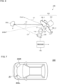
- Fig. 7 is a block diagram showing an automobile provided with the object identification system 10.
- An automobile 300 is provided with headlamps 302L and 302R. At least one from among the headlamps 302L and 302R is provided with the object identification system 10 as a built-in component.
- Each headlamp 302 is positioned at a frontmost end of the vehicle body, which is most advantageous as a position where the distance sensor 100 is to be installed for detecting an object in the vicinity.
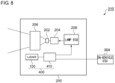
- the information with respect to the object OBJ detected by the processing device 410 may be used to support the light distribution control operation of the automotive lamp 200.
- a lamp ECU 208 generates a suitable light distribution pattern based on the information with respect to the kind of the object OBJ and the position thereof generated by the processing device 410.
- the lighting circuit 204 and the optical system 206 operate so as to provide the light distribution pattern generated by the lamp ECU 208.
- the information with respect to the object OBJ detected by the processing device 410 may be transmitted to the in-vehicle ECU 304.
- the in-vehicle ECU may support autonomous driving based on the information thus transmitted.
- the object may be defined as a different kind (category) for each orientation as viewed from the user's vehicle. That is to say, the same object is identified as a different kind according to the orientation thereof, e.g., whether or not the object is positioned with a face-to-face orientation with respect to the user's vehicle. This is because such identification is advantageous in estimating the object OBJ moving direction.
- the processing device 40 may be configured of only a hardware component using an FPGA or the like.
- the present invention relates to an object identification system.
- 10 object identification system 20 distance sensor, 40 processing device, 42 classifier, 50 input layer, 52 intermediate layer, 54 output layer, 70 learning system, 72 LiDAR, 74 computer, 100 distance sensor, 110 light source, 120 scanning device, 122 motor, 124 rotational shaft, 126 mirror, 130 photosensor, 140 processor, 200 automotive lamp, 202 light source, 204 lighting circuit, 206 optical system, 300 automobile, 302 headlamp, 304 in-vehicle ECU, 310 lamp system, vehicle ECU, 310 lamp system, 400 object detection system, 410 processing device.
Landscapes
- Engineering & Computer Science (AREA)
- Physics & Mathematics (AREA)
- General Physics & Mathematics (AREA)
- Theoretical Computer Science (AREA)
- Data Mining & Analysis (AREA)
- Remote Sensing (AREA)
- Evolutionary Computation (AREA)
- Radar, Positioning & Navigation (AREA)
- Life Sciences & Earth Sciences (AREA)
- Artificial Intelligence (AREA)
- Computer Networks & Wireless Communication (AREA)
- General Engineering & Computer Science (AREA)
- Electromagnetism (AREA)
- Multimedia (AREA)
- Computational Linguistics (AREA)
- Computing Systems (AREA)
- Software Systems (AREA)
- Mathematical Physics (AREA)
- Health & Medical Sciences (AREA)
- Biomedical Technology (AREA)
- Biophysics (AREA)
- Molecular Biology (AREA)
- General Health & Medical Sciences (AREA)
- Bioinformatics & Cheminformatics (AREA)
- Evolutionary Biology (AREA)
- Bioinformatics & Computational Biology (AREA)
- Computer Vision & Pattern Recognition (AREA)
- Optical Radar Systems And Details Thereof (AREA)
- Traffic Control Systems (AREA)
Claims (8)
- Objektidentifikationssystem (10) zum Montieren an einem Fahrzeug, das Folgendes umfasst:einen Abstandssensor (20), der dazu strukturiert ist, einen einzelnen Strahl in einer horizontalen Richtung abzutasten, um Abstände zu Punkten auf einer Oberfläche eines Objekts (OBJ) zu messen, und ein einzelnes Element aus Punktwolkendaten, PCD, zu erzeugen, das einer einzelnen Abtastlinie entspricht; undeine Verarbeitungsvorrichtung (40), die einen Klassifizierer (42) umfasst, der dazu strukturiert ist, eine Art des Objekts (OBJ) basierend auf dem einzelnen Element aus Punktwolkendaten zu identifizieren, das der einzelnen Abtastlinie entspricht, die durch den Abstandssensor (20) erzeugt wurde,wobei der Klassifizierer (42) basierend auf einem durch maschinelles Lernen erzeugten gelernten Modell implementiert wird,und wobei das maschinelle Lernen unter Verwendung mehrerer Elemente aus Punktwolkendaten ausgeführt wird, die mehreren Abtastlinien entsprechen, die durch Messen eines vorbestimmten Objekts mittels einer Lichtdetektion und Entfernungsmessung, LiDAR (72), erhalten wurden, die mehrere Abtastlinien mit unterschiedlichen Höhen unterstützt, wobei sich die LiDAR von dem Abstandssensor (20) unterscheidet.
- Objektidentifikationssystem (10) nach Anspruch 1, wobei der Abstandssensor (20, 100) Folgendes umfasst:eine Lichtquelle (110);eine Abtastvorrichtung (120), die einen Motor (122) und einen Spiegel (126) umfasst, der an dem Motor (122) angebracht und dazu strukturiert ist, emittiertes Licht der Lichtquelle (110) zu reflektieren, wobei die Abtastvorrichtung (120) so strukturiert ist, dass Sondenlicht (L2), das von dem Spiegel reflektiertes Licht ist, gemäß einer Drehung des Motors (122) abgetastet werden kann;einen Fotosensor (130), der dazu strukturiert ist, Rücklicht (L3) zu detektieren, das das Sondenlicht (L2) ist, das von einem Punkt (P) auf einem Objekt (OBJ) reflektiert wird; undeinen Prozessor (140), der dazu strukturiert ist, einen Abstand zu dem Punkt (P) auf dem Objekt (OBJ) basierend auf einer Ausgabe des Fotosensors (130) zu detektieren.
- Objektidentifikationssystem (10) nach Anspruch 1 oder 2, wobei der Klassifizierer (42) ein neuronales Netzwerk umfasst.
- Kraftfahrzeug (300), das das Objektidentifikationssystem (10) nach einem der Ansprüche 1 bis 3 umfasst.
- Kraftfahrzeug (300) nach Anspruch 4, wobei der Abstandssensor (20) in einen Scheinwerfer (302) eingebaut ist.
- Kraftfahrzeugleuchte (200), die das Objektidentifikationssystem (400) nach einem der Ansprüche 1 bis 3 umfasst.
- Verfahren für einen Klassifizierer, der dazu strukturiert ist, eine Art eines Objekts basierend auf einem einzelnen Element aus Punktwolkendaten zu identifizieren, das einer einzelnen Abtastlinie entspricht, die durch einen Abstandssensor erfasst wurde,
wobei das Verfahren Folgendes umfasst:Messen eines vorbestimmten Objekts unter Verwendung einer Lichtdetektion und Entfernungsmessung, LiDAR, die als eine Komponente strukturiert ist, die sich von dem Abstandssensor unterscheidet, und dazu strukturiert ist, mehrere Abtastlinien mit unterschiedlichen Höhen zu unterstützen;Ausführen von maschinellem Lernen mit mehreren Elementen aus Punktwolkendaten, die den mehreren Abtastlinien entsprechen, als Trainingsdaten, um zu ermöglichen, dass das Objekt identifiziert wird; undImplementieren des Klassifizierers basierend auf einem durch das maschinelle Lernen erzeugten gelernten Modell. - Verarbeitungsvorrichtung (40) für das Objektidentifikationssystem (10) nach einem der vorhergehenden Ansprüche 1-3, die einen Klassifizierer (42) umfasst, der dazu strukturiert ist, das einzelne Element aus Punktwolkendaten zu empfangen, das der einzelnen Abtastlinie entspricht, die durch den Abstandssensor (20) erfasst wurde,wobei der Klassifizierer (42) basierend auf einem durch maschinelles Lernen erzeugten gelernten Modell implementiert wird,und wobei das maschinelle Lernen unter Verwendung mehrerer Elemente aus Punktwolkendaten ausgeführt wird, die mehreren Abtastlinien entsprechen, die durch Messen eines vorbestimmten Objekts mittels einer Lichtdetektion und Entfernungsmessung, LiDAR, erhalten werden, die mehrere Abtastlinien mit unterschiedlichen Höhen unterstützt, wobei sich die LiDAR von dem Abstandssensor (20) unterscheidet.
Applications Claiming Priority (2)
| Application Number | Priority Date | Filing Date | Title |
|---|---|---|---|
| JP2018225762 | 2018-11-30 | ||
| PCT/JP2019/045095 WO2020110802A1 (ja) | 2018-11-30 | 2019-11-18 | 車載用物体識別システム、自動車、車両用灯具、分類器の学習方法、演算処理装置 |
Publications (3)
| Publication Number | Publication Date |
|---|---|
| EP3889646A1 EP3889646A1 (de) | 2021-10-06 |
| EP3889646A4 EP3889646A4 (de) | 2022-01-12 |
| EP3889646B1 true EP3889646B1 (de) | 2025-06-25 |
Family
ID=70852870
Family Applications (1)
| Application Number | Title | Priority Date | Filing Date |
|---|---|---|---|
| EP19890797.4A Active EP3889646B1 (de) | 2018-11-30 | 2019-11-18 | Fahrzeuginternes objektidentifizierungssystem, kraftfahrzeug, fahrzeuglampe, klassifikatorlernverfahren und rechenoperationsvorrichtung |
Country Status (5)
| Country | Link |
|---|---|
| US (1) | US20210286081A1 (de) |
| EP (1) | EP3889646B1 (de) |
| JP (1) | JP7288460B2 (de) |
| CN (1) | CN111259722A (de) |
| WO (1) | WO2020110802A1 (de) |
Families Citing this family (2)
| Publication number | Priority date | Publication date | Assignee | Title |
|---|---|---|---|---|
| US12270908B2 (en) * | 2021-11-01 | 2025-04-08 | GM Global Technology Operations LLC | Virtual beams for identification of edge and planar points in lidar point cloud obtained with vehicle lidar system |
| JP7725414B2 (ja) * | 2022-04-14 | 2025-08-19 | 株式会社国際電気 | 監視システム及び監視方法 |
Family Cites Families (18)
| Publication number | Priority date | Publication date | Assignee | Title |
|---|---|---|---|---|
| JP3376864B2 (ja) * | 1997-07-23 | 2003-02-10 | 株式会社デンソー | 車両用障害物認識装置 |
| JP2002236178A (ja) * | 2001-02-07 | 2002-08-23 | Honda Motor Co Ltd | 移動体における物体検知装置 |
| JP2009098023A (ja) | 2007-10-17 | 2009-05-07 | Toyota Motor Corp | 物体検出装置及び物体検出方法 |
| JP2011186584A (ja) * | 2010-03-05 | 2011-09-22 | Daihatsu Motor Co Ltd | 物体認識装置 |
| JP6382525B2 (ja) * | 2014-02-10 | 2018-08-29 | 株式会社デンソー | 物体識別方法、および物体識別装置 |
| CN103963801A (zh) * | 2014-05-23 | 2014-08-06 | 成都睿感科技有限公司 | 基于测距传感器解决站内轨道电路区段分路不良的系统 |
| JP6411942B2 (ja) * | 2015-04-23 | 2018-10-24 | 株式会社デンソー | 物体認識装置 |
| US9576185B1 (en) | 2015-09-14 | 2017-02-21 | Toyota Motor Engineering & Manufacturing North America, Inc. | Classifying objects detected by 3D sensors for autonomous vehicle operation |
| CN107924040A (zh) * | 2016-02-19 | 2018-04-17 | 索尼公司 | 图像拾取装置、图像拾取控制方法和程序 |
| CN108780154B (zh) * | 2016-03-14 | 2023-06-09 | 亿目朗欧洲股份有限公司 | 3d点云的处理方法 |
| CN106291506A (zh) * | 2016-08-16 | 2017-01-04 | 长春理工大学 | 基于单线点云数据机器学习的车辆目标识别方法及装置 |
| CN106371106A (zh) * | 2016-08-16 | 2017-02-01 | 长春理工大学 | 单线激光雷达人形目标识别方法、装置和汽车 |
| CN106371104A (zh) * | 2016-08-16 | 2017-02-01 | 长春理工大学 | 多线点云数据机器学习的车辆目标识别方法及防撞装置 |
| CN106371105A (zh) * | 2016-08-16 | 2017-02-01 | 长春理工大学 | 单线激光雷达车辆目标识别方法、装置和汽车 |
| CN106570454B (zh) * | 2016-10-10 | 2019-06-11 | 同济大学 | 基于移动激光扫描的行人交通参数提取方法 |
| KR102642239B1 (ko) * | 2016-12-22 | 2024-03-04 | 현대자동차주식회사 | 차량 및 그 제어 방법 |
| JP6782433B2 (ja) * | 2017-03-22 | 2020-11-11 | パナソニックIpマネジメント株式会社 | 画像認識装置 |
| US10460180B2 (en) * | 2017-04-20 | 2019-10-29 | GM Global Technology Operations LLC | Systems and methods for visual classification with region proposals |
-
2019
- 2019-11-18 WO PCT/JP2019/045095 patent/WO2020110802A1/ja not_active Ceased
- 2019-11-18 EP EP19890797.4A patent/EP3889646B1/de active Active
- 2019-11-18 JP JP2020558380A patent/JP7288460B2/ja active Active
- 2019-11-26 CN CN201911171236.0A patent/CN111259722A/zh active Pending
-
2021
- 2021-05-26 US US17/330,519 patent/US20210286081A1/en not_active Abandoned
Also Published As
| Publication number | Publication date |
|---|---|
| JP7288460B2 (ja) | 2023-06-07 |
| WO2020110802A1 (ja) | 2020-06-04 |
| EP3889646A1 (de) | 2021-10-06 |
| CN111259722A (zh) | 2020-06-09 |
| JPWO2020110802A1 (ja) | 2021-10-14 |
| US20210286081A1 (en) | 2021-09-16 |
Similar Documents
| Publication | Publication Date | Title |
|---|---|---|
| JP7506829B2 (ja) | 自律車両用途のための速度推定および物体追跡 | |
| EP3229041B1 (de) | Objekterfassung mittels radar- und sichtdefiniertem bilderfassungsbereich | |
| CN107144839B (zh) | 通过传感器融合检测长对象 | |
| CN113743171B (zh) | 目标检测方法及装置 | |
| US11341604B2 (en) | Processing device for object identification | |
| JP7413935B2 (ja) | 車載センサシステム | |
| US20090122136A1 (en) | Object detection device | |
| US20240151855A1 (en) | Lidar-based object tracking | |
| US11754714B2 (en) | Recognition sensor and control method thereof, automobile, automotive lamp, object recognition system, and object recognition method | |
| US20240302529A1 (en) | Method for estimating the speed of a vehicle | |
| EP3540467B1 (de) | Entfernungsmesssystem, entfernungsbestimmungsverfahren, fahrzeuginterne vorrichtung und fahrzeug | |
| CN111645671A (zh) | 车辆自动停放方法及其自动驾驶车辆 | |
| EP3889646B1 (de) | Fahrzeuginternes objektidentifizierungssystem, kraftfahrzeug, fahrzeuglampe, klassifikatorlernverfahren und rechenoperationsvorrichtung | |
| WO2019198789A1 (ja) | オブジェクト識別システム、自動車、車両用灯具、オブジェクトのクラスタリング方法 | |
| CN116136414A (zh) | 传感器定位 | |
| EP4379424A1 (de) | Mehrweg-objektidentifikation zur navigation | |
| US12475597B2 (en) | Robust lidar-to-camera sensor alignment | |
| CN118675142A (zh) | 稳健的激光雷达到相机传感器对准 | |
| US12466433B2 (en) | Autonomous driving LiDAR technology | |
| CN110095776B (zh) | 用于确定对象的存在和/或特性的方法和周围环境识别设备 | |
| US12032066B2 (en) | Recognition device and method | |
| JP4850531B2 (ja) | 車載レーダ装置 | |
| US11841435B2 (en) | Object identification system | |
| US12487354B2 (en) | Content capture of an environment of a vehicle using a priori confidence levels | |
| US20240219565A1 (en) | Systems and methods for detecting and measuring object velocity using single scan lidar detection |
Legal Events
| Date | Code | Title | Description |
|---|---|---|---|
| STAA | Information on the status of an ep patent application or granted ep patent |
Free format text: STATUS: THE INTERNATIONAL PUBLICATION HAS BEEN MADE |
|
| PUAI | Public reference made under article 153(3) epc to a published international application that has entered the european phase |
Free format text: ORIGINAL CODE: 0009012 |
|
| STAA | Information on the status of an ep patent application or granted ep patent |
Free format text: STATUS: REQUEST FOR EXAMINATION WAS MADE |
|
| 17P | Request for examination filed |
Effective date: 20210609 |
|
| AK | Designated contracting states |
Kind code of ref document: A1 Designated state(s): AL AT BE BG CH CY CZ DE DK EE ES FI FR GB GR HR HU IE IS IT LI LT LU LV MC MK MT NL NO PL PT RO RS SE SI SK SM TR |
|
| A4 | Supplementary search report drawn up and despatched |
Effective date: 20211213 |
|
| RIC1 | Information provided on ipc code assigned before grant |
Ipc: G06K 9/62 20060101ALI20211207BHEP Ipc: G06K 9/00 20060101ALI20211207BHEP Ipc: G01S 7/48 20060101ALI20211207BHEP Ipc: G01S 7/481 20060101ALI20211207BHEP Ipc: G01S 17/931 20200101ALI20211207BHEP Ipc: G08G 1/16 20060101ALI20211207BHEP Ipc: G06T 7/521 20170101ALI20211207BHEP Ipc: G06T 7/00 20170101ALI20211207BHEP Ipc: G01S 17/89 20200101AFI20211207BHEP |
|
| DAV | Request for validation of the european patent (deleted) | ||
| DAX | Request for extension of the european patent (deleted) | ||
| GRAP | Despatch of communication of intention to grant a patent |
Free format text: ORIGINAL CODE: EPIDOSNIGR1 |
|
| STAA | Information on the status of an ep patent application or granted ep patent |
Free format text: STATUS: GRANT OF PATENT IS INTENDED |
|
| RIC1 | Information provided on ipc code assigned before grant |
Ipc: G06N 3/08 20060101ALN20250410BHEP Ipc: G06V 20/58 20220101ALI20250410BHEP Ipc: G08G 1/015 20060101ALI20250410BHEP Ipc: G01S 7/481 20060101ALI20250410BHEP Ipc: G01S 17/931 20200101ALI20250410BHEP Ipc: G01S 7/48 20060101ALI20250410BHEP Ipc: G01S 17/89 20200101AFI20250410BHEP |
|
| GRAS | Grant fee paid |
Free format text: ORIGINAL CODE: EPIDOSNIGR3 |
|
| INTG | Intention to grant announced |
Effective date: 20250422 |
|
| GRAA | (expected) grant |
Free format text: ORIGINAL CODE: 0009210 |
|
| STAA | Information on the status of an ep patent application or granted ep patent |
Free format text: STATUS: THE PATENT HAS BEEN GRANTED |
|
| AK | Designated contracting states |
Kind code of ref document: B1 Designated state(s): AL AT BE BG CH CY CZ DE DK EE ES FI FR GB GR HR HU IE IS IT LI LT LU LV MC MK MT NL NO PL PT RO RS SE SI SK SM TR |
|
| REG | Reference to a national code |
Ref country code: GB Ref legal event code: FG4D |
|
| REG | Reference to a national code |
Ref country code: CH Ref legal event code: EP |
|
| REG | Reference to a national code |
Ref country code: CH Ref legal event code: EP |
|
| REG | Reference to a national code |
Ref country code: IE Ref legal event code: FG4D |
|
| REG | Reference to a national code |
Ref country code: DE Ref legal event code: R096 Ref document number: 602019071742 Country of ref document: DE |
|
| P01 | Opt-out of the competence of the unified patent court (upc) registered |
Free format text: CASE NUMBER: APP_29014/2025 Effective date: 20250618 |
|
| PG25 | Lapsed in a contracting state [announced via postgrant information from national office to epo] |
Ref country code: FI Free format text: LAPSE BECAUSE OF FAILURE TO SUBMIT A TRANSLATION OF THE DESCRIPTION OR TO PAY THE FEE WITHIN THE PRESCRIBED TIME-LIMIT Effective date: 20250625 |
|
| REG | Reference to a national code |
Ref country code: LT Ref legal event code: MG9D |
|
| PG25 | Lapsed in a contracting state [announced via postgrant information from national office to epo] |
Ref country code: NO Free format text: LAPSE BECAUSE OF FAILURE TO SUBMIT A TRANSLATION OF THE DESCRIPTION OR TO PAY THE FEE WITHIN THE PRESCRIBED TIME-LIMIT Effective date: 20250925 Ref country code: GR Free format text: LAPSE BECAUSE OF FAILURE TO SUBMIT A TRANSLATION OF THE DESCRIPTION OR TO PAY THE FEE WITHIN THE PRESCRIBED TIME-LIMIT Effective date: 20250926 |
|
| PG25 | Lapsed in a contracting state [announced via postgrant information from national office to epo] |
Ref country code: BG Free format text: LAPSE BECAUSE OF FAILURE TO SUBMIT A TRANSLATION OF THE DESCRIPTION OR TO PAY THE FEE WITHIN THE PRESCRIBED TIME-LIMIT Effective date: 20250625 |
|
| PG25 | Lapsed in a contracting state [announced via postgrant information from national office to epo] |
Ref country code: HR Free format text: LAPSE BECAUSE OF FAILURE TO SUBMIT A TRANSLATION OF THE DESCRIPTION OR TO PAY THE FEE WITHIN THE PRESCRIBED TIME-LIMIT Effective date: 20250625 |
|
| PGFP | Annual fee paid to national office [announced via postgrant information from national office to epo] |
Ref country code: FR Payment date: 20250930 Year of fee payment: 7 |
|
| PG25 | Lapsed in a contracting state [announced via postgrant information from national office to epo] |
Ref country code: RS Free format text: LAPSE BECAUSE OF FAILURE TO SUBMIT A TRANSLATION OF THE DESCRIPTION OR TO PAY THE FEE WITHIN THE PRESCRIBED TIME-LIMIT Effective date: 20250925 |
|
| PG25 | Lapsed in a contracting state [announced via postgrant information from national office to epo] |
Ref country code: LV Free format text: LAPSE BECAUSE OF FAILURE TO SUBMIT A TRANSLATION OF THE DESCRIPTION OR TO PAY THE FEE WITHIN THE PRESCRIBED TIME-LIMIT Effective date: 20250625 |
|
| REG | Reference to a national code |
Ref country code: NL Ref legal event code: MP Effective date: 20250625 |
|
| PG25 | Lapsed in a contracting state [announced via postgrant information from national office to epo] |
Ref country code: NL Free format text: LAPSE BECAUSE OF FAILURE TO SUBMIT A TRANSLATION OF THE DESCRIPTION OR TO PAY THE FEE WITHIN THE PRESCRIBED TIME-LIMIT Effective date: 20250625 |
|
| PG25 | Lapsed in a contracting state [announced via postgrant information from national office to epo] |
Ref country code: PT Free format text: LAPSE BECAUSE OF FAILURE TO SUBMIT A TRANSLATION OF THE DESCRIPTION OR TO PAY THE FEE WITHIN THE PRESCRIBED TIME-LIMIT Effective date: 20251027 |
|
| REG | Reference to a national code |
Ref country code: AT Ref legal event code: MK05 Ref document number: 1807018 Country of ref document: AT Kind code of ref document: T Effective date: 20250625 |
|
| PG25 | Lapsed in a contracting state [announced via postgrant information from national office to epo] |
Ref country code: IS Free format text: LAPSE BECAUSE OF FAILURE TO SUBMIT A TRANSLATION OF THE DESCRIPTION OR TO PAY THE FEE WITHIN THE PRESCRIBED TIME-LIMIT Effective date: 20251025 |
|
| PGFP | Annual fee paid to national office [announced via postgrant information from national office to epo] |
Ref country code: DE Payment date: 20250930 Year of fee payment: 7 |
|
| PG25 | Lapsed in a contracting state [announced via postgrant information from national office to epo] |
Ref country code: AT Free format text: LAPSE BECAUSE OF FAILURE TO SUBMIT A TRANSLATION OF THE DESCRIPTION OR TO PAY THE FEE WITHIN THE PRESCRIBED TIME-LIMIT Effective date: 20250625 Ref country code: SM Free format text: LAPSE BECAUSE OF FAILURE TO SUBMIT A TRANSLATION OF THE DESCRIPTION OR TO PAY THE FEE WITHIN THE PRESCRIBED TIME-LIMIT Effective date: 20250625 |
|
| PG25 | Lapsed in a contracting state [announced via postgrant information from national office to epo] |
Ref country code: CZ Free format text: LAPSE BECAUSE OF FAILURE TO SUBMIT A TRANSLATION OF THE DESCRIPTION OR TO PAY THE FEE WITHIN THE PRESCRIBED TIME-LIMIT Effective date: 20250625 |
|
| PG25 | Lapsed in a contracting state [announced via postgrant information from national office to epo] |
Ref country code: PL Free format text: LAPSE BECAUSE OF FAILURE TO SUBMIT A TRANSLATION OF THE DESCRIPTION OR TO PAY THE FEE WITHIN THE PRESCRIBED TIME-LIMIT Effective date: 20250625 |
|
| PG25 | Lapsed in a contracting state [announced via postgrant information from national office to epo] |
Ref country code: EE Free format text: LAPSE BECAUSE OF FAILURE TO SUBMIT A TRANSLATION OF THE DESCRIPTION OR TO PAY THE FEE WITHIN THE PRESCRIBED TIME-LIMIT Effective date: 20250625 |
|
| PG25 | Lapsed in a contracting state [announced via postgrant information from national office to epo] |
Ref country code: SK Free format text: LAPSE BECAUSE OF FAILURE TO SUBMIT A TRANSLATION OF THE DESCRIPTION OR TO PAY THE FEE WITHIN THE PRESCRIBED TIME-LIMIT Effective date: 20250625 |
|
| PG25 | Lapsed in a contracting state [announced via postgrant information from national office to epo] |
Ref country code: ES Free format text: LAPSE BECAUSE OF FAILURE TO SUBMIT A TRANSLATION OF THE DESCRIPTION OR TO PAY THE FEE WITHIN THE PRESCRIBED TIME-LIMIT Effective date: 20250625 |
|
| PG25 | Lapsed in a contracting state [announced via postgrant information from national office to epo] |
Ref country code: RO Free format text: LAPSE BECAUSE OF FAILURE TO SUBMIT A TRANSLATION OF THE DESCRIPTION OR TO PAY THE FEE WITHIN THE PRESCRIBED TIME-LIMIT Effective date: 20250625 |
|
| PG25 | Lapsed in a contracting state [announced via postgrant information from national office to epo] |
Ref country code: DK Free format text: LAPSE BECAUSE OF FAILURE TO SUBMIT A TRANSLATION OF THE DESCRIPTION OR TO PAY THE FEE WITHIN THE PRESCRIBED TIME-LIMIT Effective date: 20250625 |
|
| PG25 | Lapsed in a contracting state [announced via postgrant information from national office to epo] |
Ref country code: IT Free format text: LAPSE BECAUSE OF FAILURE TO SUBMIT A TRANSLATION OF THE DESCRIPTION OR TO PAY THE FEE WITHIN THE PRESCRIBED TIME-LIMIT Effective date: 20250625 |