EP3670892B1 - Arbeitsgerät mit verbrennungsmotor mit vergaser-kühlung - Google Patents
Arbeitsgerät mit verbrennungsmotor mit vergaser-kühlung Download PDFInfo
- Publication number
- EP3670892B1 EP3670892B1 EP19213159.7A EP19213159A EP3670892B1 EP 3670892 B1 EP3670892 B1 EP 3670892B1 EP 19213159 A EP19213159 A EP 19213159A EP 3670892 B1 EP3670892 B1 EP 3670892B1
- Authority
- EP
- European Patent Office
- Prior art keywords
- cooling air
- air flow
- cylinder
- carburettor
- carburetor
- Prior art date
- Legal status (The legal status is an assumption and is not a legal conclusion. Google has not performed a legal analysis and makes no representation as to the accuracy of the status listed.)
- Active
Links
Images


Classifications
-
- F—MECHANICAL ENGINEERING; LIGHTING; HEATING; WEAPONS; BLASTING
- F02—COMBUSTION ENGINES; HOT-GAS OR COMBUSTION-PRODUCT ENGINE PLANTS
- F02M—SUPPLYING COMBUSTION ENGINES IN GENERAL WITH COMBUSTIBLE MIXTURES OR CONSTITUENTS THEREOF
- F02M15/00—Carburettors with heating, cooling or thermal insulating means for combustion-air, fuel, or fuel-air mixture
-
- F—MECHANICAL ENGINEERING; LIGHTING; HEATING; WEAPONS; BLASTING
- F01—MACHINES OR ENGINES IN GENERAL; ENGINE PLANTS IN GENERAL; STEAM ENGINES
- F01P—COOLING OF MACHINES OR ENGINES IN GENERAL; COOLING OF INTERNAL-COMBUSTION ENGINES
- F01P1/00—Air cooling
- F01P1/02—Arrangements for cooling cylinders or cylinder heads, e.g. ducting cooling-air from its pressure source to cylinders or along cylinders
-
- F—MECHANICAL ENGINEERING; LIGHTING; HEATING; WEAPONS; BLASTING
- F01—MACHINES OR ENGINES IN GENERAL; ENGINE PLANTS IN GENERAL; STEAM ENGINES
- F01P—COOLING OF MACHINES OR ENGINES IN GENERAL; COOLING OF INTERNAL-COMBUSTION ENGINES
- F01P1/00—Air cooling
- F01P1/06—Arrangements for cooling other engine or machine parts
-
- F—MECHANICAL ENGINEERING; LIGHTING; HEATING; WEAPONS; BLASTING
- F01—MACHINES OR ENGINES IN GENERAL; ENGINE PLANTS IN GENERAL; STEAM ENGINES
- F01P—COOLING OF MACHINES OR ENGINES IN GENERAL; COOLING OF INTERNAL-COMBUSTION ENGINES
- F01P5/00—Pumping cooling-air or liquid coolants
- F01P5/02—Pumping cooling-air; Arrangements of cooling-air pumps, e.g. fans or blowers
- F01P5/06—Guiding or ducting air to, or from, ducted fans
-
- F—MECHANICAL ENGINEERING; LIGHTING; HEATING; WEAPONS; BLASTING
- F02—COMBUSTION ENGINES; HOT-GAS OR COMBUSTION-PRODUCT ENGINE PLANTS
- F02M—SUPPLYING COMBUSTION ENGINES IN GENERAL WITH COMBUSTIBLE MIXTURES OR CONSTITUENTS THEREOF
- F02M17/00—Carburettors having pertinent characteristics not provided for in, or of interest apart from, the apparatus of preceding main groups F02M1/00 - F02M15/00
- F02M17/02—Floatless carburettors
- F02M17/04—Floatless carburettors having fuel inlet valve controlled by diaphragm
-
- F—MECHANICAL ENGINEERING; LIGHTING; HEATING; WEAPONS; BLASTING
- F02—COMBUSTION ENGINES; HOT-GAS OR COMBUSTION-PRODUCT ENGINE PLANTS
- F02M—SUPPLYING COMBUSTION ENGINES IN GENERAL WITH COMBUSTIBLE MIXTURES OR CONSTITUENTS THEREOF
- F02M31/00—Apparatus for thermally treating combustion-air, fuel, or fuel-air mixture
- F02M31/02—Apparatus for thermally treating combustion-air, fuel, or fuel-air mixture for heating
- F02M31/04—Apparatus for thermally treating combustion-air, fuel, or fuel-air mixture for heating combustion-air or fuel-air mixture
-
- F—MECHANICAL ENGINEERING; LIGHTING; HEATING; WEAPONS; BLASTING
- F02—COMBUSTION ENGINES; HOT-GAS OR COMBUSTION-PRODUCT ENGINE PLANTS
- F02B—INTERNAL-COMBUSTION PISTON ENGINES; COMBUSTION ENGINES IN GENERAL
- F02B63/00—Adaptations of engines for driving pumps, hand-held tools or electric generators; Portable combinations of engines with engine-driven devices
- F02B63/02—Adaptations of engines for driving pumps, hand-held tools or electric generators; Portable combinations of engines with engine-driven devices for hand-held tools
-
- F—MECHANICAL ENGINEERING; LIGHTING; HEATING; WEAPONS; BLASTING
- F02—COMBUSTION ENGINES; HOT-GAS OR COMBUSTION-PRODUCT ENGINE PLANTS
- F02F—CYLINDERS, PISTONS OR CASINGS, FOR COMBUSTION ENGINES; ARRANGEMENTS OF SEALINGS IN COMBUSTION ENGINES
- F02F1/00—Cylinders; Cylinder heads
- F02F1/24—Cylinder heads
- F02F1/26—Cylinder heads having cooling means
- F02F1/28—Cylinder heads having cooling means for air cooling
- F02F1/30—Finned cylinder heads
- F02F1/34—Finned cylinder heads with means for directing or distributing cooling medium
-
- F—MECHANICAL ENGINEERING; LIGHTING; HEATING; WEAPONS; BLASTING
- F02—COMBUSTION ENGINES; HOT-GAS OR COMBUSTION-PRODUCT ENGINE PLANTS
- F02M—SUPPLYING COMBUSTION ENGINES IN GENERAL WITH COMBUSTIBLE MIXTURES OR CONSTITUENTS THEREOF
- F02M35/00—Combustion-air cleaners, air intakes, intake silencers, or induction systems specially adapted for, or arranged on, internal-combustion engines
- F02M35/02—Air cleaners
- F02M35/04—Air cleaners specially arranged with respect to engine, to intake system or specially adapted to vehicle; Mounting thereon ; Combinations with other devices
- F02M35/06—Air cleaners specially arranged with respect to engine, to intake system or specially adapted to vehicle; Mounting thereon ; Combinations with other devices combined or associated with engine's cooling blower or fan, or with flywheel
-
- F—MECHANICAL ENGINEERING; LIGHTING; HEATING; WEAPONS; BLASTING
- F02—COMBUSTION ENGINES; HOT-GAS OR COMBUSTION-PRODUCT ENGINE PLANTS
- F02M—SUPPLYING COMBUSTION ENGINES IN GENERAL WITH COMBUSTIBLE MIXTURES OR CONSTITUENTS THEREOF
- F02M35/00—Combustion-air cleaners, air intakes, intake silencers, or induction systems specially adapted for, or arranged on, internal-combustion engines
- F02M35/10—Air intakes; Induction systems
- F02M35/1015—Air intakes; Induction systems characterised by the engine type
- F02M35/1017—Small engines, e.g. for handheld tools, or model engines; Single cylinder engines
-
- F—MECHANICAL ENGINEERING; LIGHTING; HEATING; WEAPONS; BLASTING
- F02—COMBUSTION ENGINES; HOT-GAS OR COMBUSTION-PRODUCT ENGINE PLANTS
- F02M—SUPPLYING COMBUSTION ENGINES IN GENERAL WITH COMBUSTIBLE MIXTURES OR CONSTITUENTS THEREOF
- F02M35/00—Combustion-air cleaners, air intakes, intake silencers, or induction systems specially adapted for, or arranged on, internal-combustion engines
- F02M35/10—Air intakes; Induction systems
- F02M35/1015—Air intakes; Induction systems characterised by the engine type
- F02M35/10196—Carburetted engines
-
- Y—GENERAL TAGGING OF NEW TECHNOLOGICAL DEVELOPMENTS; GENERAL TAGGING OF CROSS-SECTIONAL TECHNOLOGIES SPANNING OVER SEVERAL SECTIONS OF THE IPC; TECHNICAL SUBJECTS COVERED BY FORMER USPC CROSS-REFERENCE ART COLLECTIONS [XRACs] AND DIGESTS
- Y02—TECHNOLOGIES OR APPLICATIONS FOR MITIGATION OR ADAPTATION AGAINST CLIMATE CHANGE
- Y02T—CLIMATE CHANGE MITIGATION TECHNOLOGIES RELATED TO TRANSPORTATION
- Y02T10/00—Road transport of goods or passengers
- Y02T10/10—Internal combustion engine [ICE] based vehicles
- Y02T10/12—Improving ICE efficiencies
Definitions
- the invention relates to a working device with an internal combustion engine according to claim 1.
- Combustion engines especially two-stroke or four-stroke engines, are known in a wide variety of forms.
- two-stroke engines have proven to be useful for driving work equipment, such as rammers for soil compaction or motor-driven drilling and/or impact hammers.
- Such an internal combustion engine usually has one or more cylinders, in each of which a piston can move axially back and forth to drive an engine shaft (crankshaft) to rotate.
- the crankshaft is in turn mounted in a crankcase, and additional lubrication devices can be provided.
- Two-stroke engines have a carburettor, for example a diaphragm carburettor, which is used to generate the air-fuel mixture required for combustion in a known manner.
- the diaphragm carburettors are usually attached to the outside near the cylinder and are cooled by natural convection.
- a fan is usually provided to cool the cylinder, which generates an air flow that is guided over the cylinder and the crankcase.
- Typical diaphragm carburettors are designed in such a way that they have a diaphragm side and a valve side, between which an air channel is led through which the combustion air for the cylinder is supplied. With the help of the carburettor, fuel is mixed in the air channel so that an air-fuel mixture is created, which can then be led to the combustion chamber in the cylinder.
- a chainsaw is disclosed in which a carburetor box can be arranged in the engine housing.
- the carburetor heats up considerably. Natural convection may then no longer be sufficient to prevent the formation of vapor bubbles in the fuel system due to the evaporation of fuel. However, if vapor bubbles form in the fuel system, particularly in the fuel supply, the suction effect of the diaphragm pump in the carburetor is reduced or even completely eliminated, so that no more fuel can be pumped. The two-stroke engine then stops due to an acute lack of fuel.
- the invention is therefore based on the object of specifying a working device with an internal combustion engine in which the risk of the formation of vapor bubbles in the fuel system can be reduced.
- An internal combustion engine is specified, with a cylinder in which a piston can move axially back and forth in order to drive an engine shaft in rotation, a carburetor device for generating an air-fuel mixture for a combustion process in the cylinder, a fan device for generating a cooling air flow, a cooling air guide for guiding the cooling air flow generated by the fan device, a flow divider for dividing the cooling air flow into a cylinder cooling air flow and a carburetor cooling air flow, a cylinder cooling air flow guide for guiding the cylinder cooling air flow to an outer wall of the cylinder, and with a carburetor cooling air flow guide for guiding the carburetor cooling air flow to an outer wall of the carburetor device.
- the internal combustion engine can in particular be a two-stroke engine and have a known structure with the cylinder, the piston and the engine shaft.
- a two-stroke engine with one cylinder has proven itself, for example, for driving a work device.
- the carburetor device serves in a known manner to generate the air-fuel mixture.
- a diaphragm carburetor with a known structure has proven to be effective.
- a diaphragm carburetor has the advantage that it is operated by the pressure pulses in the intake area of the engine and thus in every position, which is not guaranteed with a float carburetor, for example.
- the fan device is a known blower or a fan that serves as a fan wheel (for example a radial fan).
- the fan device can be driven directly via the motor shaft (crankshaft), so that the fan wheel can be attached directly to the motor shaft.
- the total cooling air flow generated by the fan device is divided at the flow divider so that two cooling air flows, the cylinder cooling air flow and the carburetor cooling air flow, are subsequently passed on.
- the two cooling air flows are guided separately to the desired location (the target of the flows to be cooled) in order to effectively cool both the cylinder and the carburetor.
- cylinder cooling air flow More than 80% of the (total) cooling air flow generated by the fan device is passed on as carburetor cooling air flow, while the rest of the (total) cooling air flow can be passed on as carburetor cooling air flow. Since the heat development in the cylinder is much greater, since its own heat is generated there by combustion, the cylinder cooling air flow can also be chosen to be even larger and, for example, comprise around 90% of the total cooling air flow. For cooling the carburetor, however, a smaller carburetor cooling air flow is sufficient.
- the air flows through the cylinder cooling air flow guide and the carburetor cooling air flow guide can each be diverted by 90°.
- the 90° diversion can also take place shortly before the flow divider, when the two flows are not yet divided.
- the carburetor cooling air flow can be directed directly to the carburetor.
- the cooling air guide can have a fan cover, wherein the fan cover at least partially encloses the fan device and wherein the cylinder cooling air flow guide and the carburetor cooling air flow guide are formed in the fan cover.
- the fan cover can be made of metal, plastic or both materials. If the two cooling air flow guides are formed in the fan cover, no further structural measures are required. on the combustion engine in order to, on the one hand, divide the total cooling air flow and, on the other hand, to guide the two separate cooling air flows precisely to the location where cooling is to be achieved.
- a partition wall can be provided between the cylinder and the carburetor device to maintain the separation of the carburetor cooling air flow from the cylinder cooling air flow.
- the partition wall can be arranged as a cover between the cylinder and the carburetor, for example. With its help, it is possible to keep the two cooling air flows separate from one another and to direct them to their actual destination even when the cylinder cooling air flow guide formed in the blower cover and the carburetor cooling air flow guide are no longer effective because the respective cooling air flow has already exited the blower cover.
- the carburetor device can have a fuel-carrying area that is covered by a carburetor outer wall, with the carburetor cooling air flow being guided in such a way that it hits the carburetor outer wall. It can be particularly advantageous if it hits the carburetor outer wall perpendicularly. However, a parallel or oblique flow to the carburetor outer wall can also be useful if the heat can be effectively dissipated in this way given the corresponding structural conditions of the carburetor.
- the carburetor device particularly in a diaphragm carburetor design, has a chamber or line connected to the fuel supply line (the fuel-carrying area).
- the carburetor device When the carburetor device is in operation, a slight negative pressure is created here in order to exert a suction effect on the fuel and thus achieve a pumping effect. If vapor bubbles form in this area - as explained in the introduction above - no negative pressure can be generated and thus no pumping effect can be achieved.
- the risk of vapor bubbles forming can be significantly reduced.
- the fan device can have a fan wheel, wherein the fan wheel can be located in a first plane and wherein the carburetor device, the cylinder and a crankcase forming the cylinder can be arranged in a second plane parallel to the first plane.
- the carburetor device, the cylinder and the crankcase can accordingly be located in a common plane which differs from the (first) plane of the fan wheel. This arrangement allows the fan wheel to produce a - relative to the longitudinal axis of the cylinder - Cross flow is generated, which then hits the carburetor device and the cylinder from the side.
- the carburetor cooling air flow and the cylinder cooling air flow occur with a vertical flow direction to the second level.
- a working device can be driven by the motor shaft, whereby a clutch can be provided between the motor shaft and the working device to interrupt or close a torque flow from the motor shaft to the working device, and whereby the clutch can be arranged in a third plane parallel to the first and second planes.
- the working device can be, for example, a percussion mechanism or a stamping mechanism.
- the clutch can be, for example, a centrifugal clutch which closes the torque flow from the motor shaft to the working device when a certain speed (switching speed) is exceeded. The operator can therefore start the working device by increasing the speed from idle.
- the combustion engine is used in a work device.
- the working device is a tamping device for soil compaction with a corresponding tamping mechanism or a motor-driven drilling and/or impact hammer with an impact mechanism.
- the implement can be a hand-held or hand-guided implement, whereby the carburetor cooling air flow and the cylinder cooling air flow are directed away from an operator holding the implement when the implement is used as intended. This means that the two cooling air flows do not hit the operator holding the implement. This is not only convenient because the cooling air flows as a whole would be unpleasant due to their blowing effect. The operator is also protected from being undesirably heated by the then heated cooling air flows.
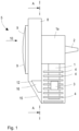
- the Fig. 1 to 4 show an internal combustion engine according to the invention in various representations.
- the internal combustion engine is designed as a two-stroke engine and can be used advantageously in various work devices, such as in particular rammers for soil compaction or motor-driven hammers (demolition hammers, drilling and/or impact hammers) for driving a corresponding work device (according to the invention a rammer or impact mechanism).
- the internal combustion engine has a cylinder 1 with a cylinder housing in which a piston (not shown) can move axially back and forth in order to drive a motor shaft 2 coupled to the crankshaft via a connecting rod and a crankshaft.
- a crankcase 1a in which the crankshaft/motor shaft 2 is mounted is connected to the cylinder 1.
- the crankshaft and the motor shaft 2 can be connected to one another in one piece.
- An air-fuel mixture is burned in the cylinder 1 to cause the piston to move.
- This air-fuel mixture is produced by a carburetor 3 serving as a carburetor device and is fed into the interior of the cylinder 1.
- the carburetor 3 is typically designed as a so-called diaphragm carburetor.
- Diaphragm carburettors have proven themselves for their intended purpose, as they can be used reliably in any position and at any inclination. Unlike float carburettors, for example, it is not necessary for a diaphragm carburettor to always be operated in a horizontal position.
- a diaphragm carburetor The structure of a diaphragm carburetor is also well known, so a detailed description is unnecessary.
- the function of a diaphragm carburetor is based that the pressure fluctuations caused by the piston in the intake tract of the engine act on an air side of a membrane, which moves in accordance with the pressure fluctuations.
- the fuel side is provided on the opposite side of the membrane.
- the movement of the membrane causes a pumping effect, so that with the help of suitable check valves (for example flutter valves) fuel is sucked in from a fuel supply and transported further.
- the fuel is finally injected into an air channel provided in the carburetor 3, so that the air-fuel mixture is formed.
- the movement of the piston and the associated suction effect in turn suck the air-fuel mixture into the combustion chamber inside the cylinder 1, where the mixture is then compressed and burned.
- the cooling fins 4 are exposed to an air flow to increase the cooling effect.
- a fan device 5 with a fan 6 serving as a fan wheel and a cooling air guide 7 is provided in the combustion engine.
- the fan 6 can in particular be designed as a radial fan, as Fig. 3 shows.
- the fan 6 is located inside the fan cover 8 in a first plane, while the carburetor 3, the cylinder 1 with the piston (not shown) and the crankcase 1a are located in a common second plane, which is parallel to the first plane.
- the drive of a working device is carried out via an optional centrifugal clutch (also not shown), which is mounted at the end of the motor shaft 2 (right-hand end in Fig. 1 ) and is located in a third level.
- the fan 6 is attached directly to the motor shaft 2 and thus automatically rotates with the engine speed when the combustion engine is running.
- the rotation of the fan 6 generates a cooling air flow.
- the fan 6 is at least partially enclosed by a fan cover 8, which forms part of the cooling air duct 7.
- the fan cover 8 has several air inlets 9 in the form of circular segment-shaped air slots, through which ambient air 10 is sucked in by the fan 6.
- the fan cover 8 is thus part of the cooling air duct 7. Inside the fan cover 8, the conveying effect of the fan 6 creates a cooling air flow 11 which is guided through the cooling air duct 7.
- the blower cover 8 can also serve as a starter cover and, for example, enclose a spool on which a rope for a pull starter is wound.
- a flow divider 12 is formed, at which the cooling air flow 11 is divided into a cylinder cooling air flow 13 and a carburetor cooling air flow 14 ( Fig. 3 ).
- More than 80%, for example approximately 90%, of the total cooling air flow 11 is guided as cylinder cooling air flow 13 to the outer wall of the cylinder 1 or the cooling fins 4 in order to achieve effective cooling of the outer wall of the cylinder 1.
- a much smaller proportion of the total cooling air flow 11, namely approximately 10% of the mass flow, is branched off as carburetor cooling air flow 14 and guided to the carburetor 3 separately from the cylinder cooling air flow 13.
- the carburetor cooling air flow 14 and the carburetor cooling air flow guide 16 thus form a carburetor bypass for the total air mass flow.
- a cylinder cooling air flow guide 15 is formed in the fan cover 8, which in particular causes a deflection of the air flow by 90°.
- the cylinder cooling air flow guide 15 has an inclined wall in the fan cover 8, which causes the change in the flow direction ( Fig. 1 ).
- the cylinder cooling air flow 13 flows essentially horizontally through the gaps between the cooling fins 4, as can be seen from Fig. 1 This means that the surface of the cylinder 1, which is enlarged by the cooling fins 4, is effectively flown onto, so that a good cooling effect can be achieved.
- the air flow is particularly transverse to the longitudinal direction (main direction of the cylinder 1).
- a carburetor cooling air flow guide 16 is provided inside and in the side area of the blower cover 8, on the upper edge of which the flow divider 12 is formed and thus branches off the carburetor cooling air flow 14 as a partial flow ( Fig. 1 and 4 ).
- the carburetor cooling air flow 14 is directed to the carburetor 3, in particular to the outer wall of the carburetor 3 behind which the fuel side is located. This allows targeted cooling of the fuel side of the carburetor 3 in order to prevent the formation of vapor bubbles in the fuel supply even when operating at higher ambient temperatures.
- the carburetor cooling air flow guide 16 is inserted inside or to the side of the fan cover 8 and can, for example, be manufactured directly with it.
- the fan cover 8 can be made of plastic or metal or a combination of both, so that the additional carburetor cooling air flow guide 16 can be manufactured on the inside of the fan cover 8 without great additional effort.
- the carburetor cooling air flow guide 16 has - analogously to the cylinder cooling air flow guide 15 - an inclined wall which deflects the carburetor cooling air flow 14 by 90° so that the outer wall of the carburetor 3 can be fully hit ( Fig. 4 ).
- Fig. 5 shows a variant of the combustion engine of the Fig. 1 to 4 .
- the embodiment of Fig. 5 differs from the embodiment of the Fig. 1 to 4 in that a partition wall 17 is arranged between the carburetor 3 and the cylinder 1 or its cooling fins 4.
- the partition wall 17 serves as a cover between the cylinder 1 and the carburetor 3 and ensures that the two cooling air flows, namely the cylinder cooling air flow 13 and the carburetor cooling air flow 14, are separated from one another. This prevents the two cooling air flows from mixing, which could lead to a turbulent flow and in particular could prevent the carburetor cooling air flow 14 from actually reaching the carburetor 3.
- the partition wall 17 thus complements the two cooling air flow guides 15, 16. It can be formed in particular as a cover made of plastic or metal and also protects the carburetor 3 from the heat radiation of the cylinder 1.
- a flange (not shown) can be formed on the partition wall 17 for fastening the carburetor 3 to the flange and thus to the partition wall 17.
- the carburetor 3 can thus be held in a simple manner on the partition wall 17.
- an opening through the partition wall 17 can be provided in the flange, through which the air-fuel mixture can be guided from the carburetor 3 to the cylinder 1.
- Fig. 5 For the sake of completeness, fuel lines 18 are also shown, via which fuel can be supplied to the carburetor 3 or - e.g. for venting the diaphragm chamber - discharged.
Landscapes
- Engineering & Computer Science (AREA)
- Chemical & Material Sciences (AREA)
- Combustion & Propulsion (AREA)
- Mechanical Engineering (AREA)
- General Engineering & Computer Science (AREA)
- Cylinder Crankcases Of Internal Combustion Engines (AREA)
Description
- Die Erfindung betrifft ein Arbeitsgerät mit einem Verbrennungsmotor gemäß Anspruch 1.
- Verbrennungsmotoren, insbesondere Zweitakt- oder Viertaktmotoren sind in vielfältigen Ausprägungen bekannt. In einer besonderen Anwendung haben sich Zweitaktmotoren zum Antrieb von Arbeitsgeräten, wie zum Beispiel Stampfern zur Bodenverdichtung oder motorbetriebenen Bohr- und/oder Schlaghämmern bewährt.
- Üblicherweise weist ein derartiger Verbrennungsmotor einen oder mehrere Zylinder auf, in denen jeweils ein Kolben axial hin und her beweglich ist, um eine Motorwelle (Kurbelwelle) drehend anzutreiben. Die Kurbelwelle ist ihrerseits in einem Kurbelgehäuse gelagert, wobei zusätzliche Schmiereinrichtungen vorgesehen sein können.
- Zweitaktmotoren weisen einen Vergaser, zum Beispiel einen Membranvergaser, auf, mit dem das für die Verbrennung erforderliche Luft-Kraftstoff-Gemisch in bekannter Weise erzeugt wird. Die Membranvergaser sind in der Regel in der Nähe des Zylinders an der Außenseite befestigt und werden mittels natürlicher Konvektion gekühlt. Zur Kühlung des Zylinders ist meist ein Ventilator vorgesehen, der einen Luftstrom erzeugt, der über den Zylinder und das Kurbelgehäuse geführt wird.
- Typische Membranvergaser sind derart aufgebaut, dass sie eine Membranseite und eine Ventilseite aufweisen, zwischen denen ein Luftkanal geführt wird, über den die Verbrennungsluft für den Zylinder zugeführt wird. Mithilfe des Vergasers wird Kraftstoff im Luftkanal beigemischt, so dass ein Luft-Kraftstoff-Gemisch entsteht, das nachfolgend zum Brennraum im Zylinder geführt werden kann.
- Aus der
US 9,016,246 B2 DE 10 2009 008 055 A1 ist jeweils ein handgeführtes Arbeitsgerät mit einem Verbrennungsmotor bekannt, bei dem für einen Winterbetrieb ein Teil der Kühlluft an den Kühlrippen des Motorzylinders vorgewärmt und nachfolgend in den Vergaser geführt wird, um den Vergaser zu erwärmen. Eine ähnliche Lösung ist in derDE 36 04 166 A1 beschrieben. - In der
DE 1 281 138 B wird eine Motorkettensäge offenbart, bei der ein Vergaserkasten im Motorgehäuse angeordnet werden kann. - Bei hohen Außentemperaturen, zum Beispiel bei einem Betrieb des Verbrennungsmotors auf einer sonnenbeschienenen Baustelle, wird der Vergaser stark erwärmt. Die natürliche Konvektion reicht dann unter Umständen nicht mehr aus, um das Entstehen von Dampfblasen im Kraftstoffsystem durch Verdampfen von Kraftstoff zu verhindern. Wenn jedoch Dampfblasen im Kraftstoffsystem, insbesondere in der Kraftstoffzuführung entstehen, wird die Saugwirkung der Membranpumpe in dem Vergaser verringert oder gar vollständig aufgehoben, so dass kein Kraftstoff mehr gefördert werden kann. Der Zweitaktmotor stoppt daraufhin aufgrund akuten Kraftstoffmangels.
- Der Erfindung liegt daher die Aufgabe zugrunde, ein Arbeitsgerät mit einem Verbrennungsmotor anzugeben, bei dem die Gefahr der Bildung von Dampfblasen im Kraftstoffsystem verringert werden kann.
- Die Aufgabe wird erfindungsgemäß durch ein Arbeitsgerät mit einem Verbrennungsmotor mit den Merkmalen von Anspruch 1 gelöst. Vorteilhafte Ausgestaltungen sind in den abhängigen Ansprüchen angegeben.
- Es wird ein Verbrennungsmotor angegeben, mit einem Zylinder, in dem ein Kolben axial hin und her beweglich ist, um eine Motorwelle drehend anzutreiben, einer Vergasereinrichtung zum Erzeugen eines Luft-Kraftstoff-Gemisches für einen Verbrennungsvorgang in dem Zylinder, einer Lüftereinrichtung zum Erzeugen eines Kühlluftstroms, einer Kühlluftführung zum Führen des von der Lüftereinrichtung erzeugten Kühlluftstroms, einem Strömungsteiler zum Aufteilen des Kühlluftstroms in einen Zylinder-Kühlluftstrom und in einen Vergaser-Kühlluftstrom, einer Zylinder-Kühlluftstromführung zum Führen des Zylinder-Kühlluftstroms zu einer Außenwand des Zylinders, und mit einer Vergaser-Kühlluftstromführung zum Führen des Vergaser-Kühlluftstroms zu einer Außenwand der Vergasereinrichtung.
- Der Verbrennungsmotor kann insbesondere ein Zweitaktmotor sein und mit dem Zylinder, dem Kolben und der Motorwelle einen bekannten Aufbau aufweisen. Ein derartiger Zweitaktmotor mit einem Zylinder hat sich z.B. zum Antrieb eines Arbeitsgeräts bewährt.
- Die Vergasereinrichtung dient in an sich bekannter Weise zum Erzeugen des Luft-Kraftstoff-Gemischs. Dazu hat sich zum Beispiel ein Membranvergaser mit an sich bekanntem Aufbau bewährt. Ein Membranvergaser hat den Vorteil, dass er durch die Druckpulse im Ansaugbereich des Motors betrieben wird und dadurch in jeder Lage funktioniert, was zum Beispiel bei einem Schwimmervergaser nicht gewährleistet ist.
- Bei der Lüftereinrichtung handelt es sich um ein an sich bekanntes Gebläse bzw. einen als Lüfterrad dienenden Ventilator (zum Beispiel einen Radialventilator). Der Antrieb der Lüftereinrichtung kann direkt über die Motorwelle (Kurbelwelle) erfolgen, so dass das Lüfterrad direkt auf der Motorwelle befestigt sein kann.
- Erfindungsgemäß wird der von der Lüftereinrichtung erzeugte Gesamt-Kühlluftstrom an dem Strömungsteiler aufgeteilt, so dass nachfolgend zwei Kühlluftströme, der Zylinder-Kühlluftstrom und der Vergaser-Kühlluftstrom, weitergeführt werden. Die beiden Kühlluftströme werden getrennt voneinander zu der jeweils angestrebten Stelle (dem zu kühlenden Ziel der Ströme) geführt werden, um sowohl den Zylinder als auch den Vergaser effektiv zu kühlen.
- Dabei wird mehr als 80% des von der Lüftereinrichtung erzeugten (Gesamt-) Kühlluftstroms als Zylinderkühlluftstrom weitergeführt werden, während der Rest des (Gesamt-)Kühlluftstroms als Vergaser-Kühlluftstrom weitergeführt werden kann. Da die Wärmeentwicklung am Zylinder wesentlich größer ist, da dort durch die Verbrennung eigene Wärme erzeugt wird, kann der Zylinder-Kühlluftstrom auch noch größer gewählt werden und zum Beispiel ca. 90% des Gesamt-Kühlluftstroms aufweisen. Für die Kühlung des Vergasers ist hingegen ein kleinerer Vergaser-Kühlluftstrom ausreichend.
- Die Luftströme durch die Zylinder-Kühlluftstromführung und die Vergaser-Kühlluftstromführung können jeweils um 90° umgelenkt werden. Die Umlenkung um 90° kann aber auch bereits kurz vor dem Strömungsteiler erfolgen, wenn die beiden Ströme noch nicht geteilt sind. Mit der Umlenkung der Luftströmung um 90° kann erreicht werden, dass einerseits der Zylinder-Kühlluftstrom exakt zwischen die an der Außenwand des Zylinders vorgesehenen Kühlrippen geführt wird, um die Kühlung des Zylinders optimal zu bewirken. Andererseits kann der Vergaser-Kühlluftstrom zielgerichtet auf den Vergaser geleitet werden.
- Die Kühlluftführung kann einen Gebläsedeckel aufweisen, wobei der Gebläsedeckel wenigstens teilweise die Lüftereinrichtung umschließt und wobei in dem Gebläsedeckel die Zylinder-Kühlluftstromführung und die Vergaser-Kühlluftstromführung ausgebildet sind. Der Gebläsedeckel kann aus Metall, aus Kunststoff oder aus beiden Materialien aufgebaut sein. Wenn die beiden Kühlluftstromführungen in dem Gebläsedeckel ausgebildet sind, sind keine weiteren baulichen Maßnahmen an dem Verbrennungsmotor erforderlich, um einerseits die Teilung des Gesamt-Kühlluftstroms zu bewirken und andererseits die beiden getrennten Kühlluftströme präzise an den Ort zu führen, an dem die Kühlung bewirkt werden soll.
- Zwischen dem Zylinder und der Vergasereinrichtung kann eine Trennwand vorgesehen sein, zum Aufrechterhalten der Trennung des Vergaser-Kühlluftstroms von dem Zylinder-Kühlluftstrom. Die Trennwand kann zum Beispiel als Abdeckung zwischen dem Zylinder und dem Vergaser angeordnet sein. Mit ihrer Hilfe ist es möglich, die beiden Kühlluftströme auch dann noch voneinander getrennt zu halten und ihrem eigentlichen Ziel zuzuführen, wenn die im Gebläsedeckel ausgebildete Zylinder-Kühlluftstromführung und die Vergaser-Kühlluftstromführung nicht mehr wirksam sind, weil der jeweilige Kühlluftstrom bereits am Gebläsedeckel ausgetreten ist.
- Die Vergasereinrichtung kann einen Kraftstoff führenden Bereich aufweisen, der durch eine Vergaser-Außenwand abgedeckt ist, wobei der Vergaser-Kühlluftstrom derart geführt ist, dass er auf die Vergaser-Außenwand trifft. Dabei kann es insbesondere vorteilhaft sein, wenn er senkrecht auf die Vergaser-Außenwand trifft. Aber auch eine parallele oder schräge Anströmung der Vergaser-Außenwand kann zweckmäßig sein, wenn auf diese Weise bei entsprechenden baulichen Gegebenheiten des Vergasers die Wärme wirksam abgeführt werden kann.
- Die Vergasereinrichtung, insbesondere in einer Ausbildung als Membranvergaser, weist eine mit der Kraftstoffzuleitung verbundene Kammer bzw. Leitung (den Kraftstoff führenden Bereich) auf. Beim Betrieb der Vergasereinrichtung entsteht hier ein leichter Unterdruck, um eine Saugwirkung auf den Kraftstoff auszuüben und damit eine Pumpwirkung zu erreichen. Wenn sich in diesem Bereich - wie oben einleitend erläutert - Dampfblasen bilden, kann kein Unterdruck erzeugt und damit keine Pumpwirkung erreicht werden. Durch das gezielte Kühlen der Außenwand des Vergasers mit Hilfe des Vergaser-Kühlluftstroms kann die Gefahr einer Bildung von Dampfblasen erheblich verringert werden.
- Die Lüftereinrichtung kann ein Lüfterrad aufweisen, wobei das Lüfterrad in einer ersten Ebene liegen kann und wobei die Vergasereinrichtung, der Zylinder und ein den Zylinder bildendes Kurbelgehäuse in einer zu der ersten Ebene parallelen zweiten Ebene angeordnet sein können. Die Vergasereinrichtung, der Zylinder und das Kurbelgehäuse können dementsprechend in einer gemeinsamen Ebene liegen, die sich von der (ersten) Ebene des Lüfterrads unterscheidet. Durch diese Anordnung kann von dem Lüfterrad eine - bezogen auf die Längsachse des Zylinders - Querströmung erzeugt werden, die dann seitlich auf die Vergasereinrichtung und den Zylinder trifft. Insbesondere erfolgen dabei der Vergaser-Kühlluftstrom und der Zylinder-Kühlluftstrom mit senkrechter Strömungsrichtung auf die zweite Ebene.
- Durch die Motorwelle kann eine Arbeitsvorrichtung antreibbar sein, wobei wirkungsmäßig zwischen der Motorwelle und der Arbeitsvorrichtung eine Kupplung vorgesehen sein kann, zum Unterbrechen oder Schließen eines Drehmomentflusses von der Motorwelle zu der Arbeitsvorrichtung, und wobei die Kupplung in einer zu der ersten und der zweiten Ebene parallelen dritten Ebene angeordnet sein kann. Die Arbeitsvorrichtung kann zum Beispiel ein Schlagwerk oder ein Stampfwerk sein. Bei der Kupplung kann es sich zum Beispiel um eine Fliehkraftkupplung handeln, die bei Überschreiten einer gewissen Drehzahl (Schaltdrehzahl) den Drehmomentfluss von der Motorwelle zu der Arbeitsvorrichtung schließt. Der Bediener hat damit die Möglichkeit, durch Erhöhen der Drehzahl aus dem Leerlauf die Arbeitsvorrichtung in Gang zu versetzen.
- Der Verbrennungsmotor wird bei einem Arbeitsgerät eingesetzt.
- Bei dem Arbeitsgerät handelt es sich um eine Stampfvorrichtung zur Bodenverdichtung mit einem entsprechenden Stampfwerk oder um einen motorbetriebener Bohr- und/oder Schlaghammer mit einem Schlagwerk.
- Das Arbeitsgerät kann ein handgehaltenes oder handgeführtes Arbeitsgerät sein, wobei der Vergaser-Kühlluftstrom und der Zylinder-Kühlluftstrom bei einem bestimmungsgemäßen Gebrauch des Arbeitsgeräts von einem das Arbeitsgerät haltenden Bediener weggeführt wird. Das bedeutet, dass die beiden Kühlluftströme nicht auf den Bediener treffen, der das Arbeitsgerät hält. Das ist nicht nur deswegen komfortabel, weil die Kühlluftströme insgesamt aufgrund ihrer Gebläsewirkung unangenehm wären. Ebenso wird der Bediener auch davor geschützt, durch die dann erwärmten Kühlluftströme seinerseits unerwünscht erwärmt zu werden.
- Diese und weitere Vorteile und Merkmale der Erfindung werden nachfolgend anhand von Beispielen unter Zuhilfenahme der begleitenden Figuren näher erläutert. Es zeigen:
- Fig. 1
- eine Seitenansicht eines erfindungsgemäßen Verbrennungsmotors;
- Fig. 2
- eine Vorderansicht des Verbrennungsmotors von
Fig. 1 ; - Fig. 3
- eine Schnittdarstellung entlang des Schnitts A-A des Verbrennungsmotors von
Fig. 1 ; - Fig. 4
- eine Detailvergrößerung des Verbrennungsmotors von
Fig. 1 ; und - Fig. 5
- eine Variante des Verbrennungsmotors.
- Die
Fig. 1 bis 4 zeigen einen erfindungsgemäßen Verbrennungsmotor in verschiedenen Darstellungen. Der Verbrennungsmotor ist als Zweitaktmotor ausgebildet und kann vorteilhaft in verschiedenen Arbeitsgeräten, wie insbesondere Stampfern zur Bodenverdichtung oder motorbetriebenen Hämmern (Abbruchhämmer, Bohr- und/oder Schlaghämmer) zum Antreiben einer entsprechenden Arbeitsvorrichtung (erfindungsgemäß ein Stampfwerk oder Schlagwerk) genutzt werden. - Der Verbrennungsmotor weist einen Zylinder 1 mit einem Zylindergehäuse auf, in dem ein nicht dargestellter Kolben axial hin und her beweglich ist, um über ein Pleuel und eine Kurbelwelle eine mit der Kurbelwelle gekoppelte Motorwelle 2 drehend anzutreiben. Dabei schließt sich an den Zylinder 1 ein Kurbelgehäuse 1a an, in dem die Kurbelwelle/Motorwelle 2 gelagert ist. Die Kurbelwelle und die Motorwelle 2 können einstückig miteinander verbunden sein. Der Aufbau eines derartigen Verbrennungsmotors ist seit langem bekannt, so dass sich an dieser Stelle eine eingehendere Beschreibung zu Aufbau und Funktionsweise erübrigt.
- In dem Zylinder 1 wird ein Luft-Kraftstoff-Gemisch verbrannt, um die Bewegung des Kolbens zu bewirken. Dieses Luft-Kraftstoff-Gemisch wird von einem als Vergasereinrichtung dienenden Vergaser 3 erzeugt und in das Innere des Zylinders 1 gefördert.
- Der Vergaser 3 ist typischerweise als sogenannter Membranvergaser ausgeführt.
- Membranvergaser haben sich für den vorgesehenen Einsatzzweck bewährt, da sie in jeder Raumlage und in jeder Neigung zuverlässig eingesetzt werden können. Anders als bei zum Beispiel Schwimmervergasern ist es für einen Membranvergaser nicht erforderlich, ihn stets in einer horizontalen Ausrichtung zu betreiben.
- Auch der Aufbau eines Membranvergasers ist bekannt, so dass sich eine detaillierte Beschreibung erübrigt. Prinzipiell beruht die Funktion eines Membranvergasers darauf, dass durch die durch den Kolben im Ansaugtrakt des Motors bewirkten Druckschwankungen eine Luftseite einer Membran beaufschlagt wird, die sich entsprechend den Druckschwankungen bewegt. Auf der gegenüberliegenden Seite der Membran ist die Kraftstoffseite vorgesehen. Durch die Bewegung der Membran wird ein Pumpeffekt bewirkt, so dass mit Hilfe von geeigneten Rückschlagventilen (zum Beispiel Flatterventilen) Kraftstoff aus einer Kraftstoffversorgung angesaugt und weiterbefördert wird. Der Kraftstoff wird schließlich in einem in dem Vergaser 3 vorgesehenen Luftkanal eingespritzt, so dass sich das Luft-Kraftstoff-Gemisch bildet. Durch die Bewegung des Kolbens und die damit verbundene Saugwirkung wird wiederum das Luft-Kraftstoff-Gemisch in die Verbrennungskammer im Inneren des Zylinders 1 gesaugt, wo daraufhin die Verdichtung und Verbrennung des Gemischs erfolgt.
- Beim Betrieb des Verbrennungsmotors entsteht im Inneren des Zylinders 1 erhebliche Verbrennungswärme, die über die Außenwand des Zylinders 1 abgeführt werden muss. Zu diesem Zweck sind an der Außenwand des Zylinders eine Vielzahl von Kühlrippen 4 vorgesehen, die die Wärme von der Außenwand des Zylinders 1 abführen und insgesamt die Kühlfläche vergrößern.
- Die Kühlrippen 4 werden von einer Luftströmung angeströmt, um die Kühlwirkung zu erhöhen.
- Zu diesem Zweck ist in dem Verbrennungsmotor eine Lüftereinrichtung 5 mit einem als Lüfterrad dienenden Ventilator 6 und einer Kühlluftführung 7 vorgesehen. Der Ventilator 6 kann insbesondere als Radialventilator ausgebildet sein, wie
Fig. 3 zeigt. - Wie aus
Fig. 1 ersichtlich, liegt der Ventilator 6 im Inneren des Gebläsedeckels 8 in einer ersten Ebene, während der Vergaser 3, der Zylinder 1 mit dem nicht dargestellten Kolben sowie dem Kurbelgehäuse 1a in einer gemeinsamen zweiten Ebene liegen, die parallel zu der ersten Ebene liegt. Der Antrieb einer nicht dargestellten Arbeitsvorrichtung erfolgt über eine ebenfalls nicht dargestellte optionale Fliehkraftkupplung, die am Ende der Motorwelle 2 (rechtsseitiges Ende inFig. 1 ) aufgesteckt sein kann und in einer dritten Ebene liegt. - Der Ventilator 6 ist direkt auf der Motorwelle 2 befestigt und dreht sich somit im Betrieb des Verbrennungsmotors automatisch mit der Motordrehzahl mit. Durch die Rotation des Ventilators 6 wird ein Kühlluftstrom erzeugt. Dazu ist der Ventilator 6 wenigstens teilweise von einem Gebläsedeckel 8 umschlossen, der damit einen Teil der Kühlluftführung 7 bildet. Der Gebläsedeckel 8 weist mehrere Lufteinlässe 9 in Form von kreissegmentförmigen Luftschlitzen auf, über die durch den Ventilator 6 Umgebungsluft 10 angesaugt wird.
- Der Gebläsedeckel 8 ist somit Teil der Kühlluftführung 7. Im Inneren des Gebläsedeckels 8 entsteht durch die Förderwirkung des Ventilators 6 ein Kühlluftstrom 11, der durch die Kühlluftführung 7 geführt wird.
- Der Gebläsedeckel 8 kann gleichzeitig auch als Starterdeckel dienen und zum Beispiel eine Spule umschließen, auf der ein Seil für einen Zugstarter aufgewickelt ist.
- Im Inneren des Gebläsedeckels 8 und damit der Kühlluftführung 7 ist ein Strömungsteiler 12 ausgebildet, an dem der Kühlluftstrom 11 in einen Zylinder-Kühlluftstrom 13 und in einen Vergaser-Kühlluftstrom 14 aufgeteilt wird (
Fig. 3 ). - Dabei werden mehr als 80%, zum Beispiel ca. 90%, des gesamten Kühlluftstroms 11 als Zylinder-Kühlluftstrom 13 zu der Außenwand des Zylinders 1 bzw. den Kühlrippen 4 geführt, um eine wirksame Kühlung der Außenwand des Zylinders 1 zu erreichen. Ein sehr viel kleinerer Anteil des gesamten Kühlluftstroms 11, nämlich zum Beispiel ca. 10% des Massenstroms wird als Vergaser-Kühlluftstrom 14 abgezweigt und getrennt von dem Zylinder-Kühlluftstrom 13 zu dem Vergaser 3 geführt. Der Vergaser-Kühlluftstrom 14 und die Vergaser-Kühlluftstromführung 16 bilden insoweit einen Vergaserbypass für den Gesamtluftmassenstrom.
- Zur Führung des Zylinder-Kühlluftstroms 13 ist eine Zylinder-Kühlluftstromführung 15 in dem Gebläsedeckel 8 ausgebildet, die insbesondere eine Umlenkung der Luftströmung um 90° bewirkt. Zu diesem Zweck weist die Zylinder-Kühlluftstromführung 15 eine schräge Wand in dem Gebläsedeckel 8 auf, die die Änderung der Strömungsrichtung bewirkt (
Fig. 1 ). - Der Zylinder-Kühlluftstrom 13 strömt nach seiner Umlenkung durch die Zylinder-Kühlluftstromführung 15 im Wesentlichen horizontal durch die Zwischenräume zwischen den Kühlrippen 4, wie aus
Fig. 1 ersichtlich. Dadurch wird die durch die Kühlrippen 4 vergrößerte Oberfläche des Zylinders 1 wirkungsvoll angeströmt, so dass eine gute Kühlwirkung erreicht werden kann. Die Luftströmung erfolgt dabei insbesondere quer zur Längsrichtung (Hauptrichtung des Zylinders 1). - Zur Führung des Vergaser-Kühlluftstroms ist eine Vergaser-Kühlluftstromführung 16 im Inneren und im seitlichen Bereich des Gebläsedeckels 8 vorgesehen, an deren oberer Kante der Strömungsteiler 12 ausgebildet ist und so den Vergaser-Kühlluftstrom 14 als Teilstrom abzweigt (
Fig. 1 und4 ). - Mit Hilfe der Vergaser-Kühlluftstromführung 16 wird der Vergaser-Kühlluftstrom 14 zielgerichtet zu dem Vergaser 3, insbesondere zu derjenigen Außenwand des Vergasers 3 geführt, hinter der sich die Kraftstoffseite befindet. Dadurch kann gezielt eine Kühlung der Kraftstoffseite des Vergasers 3 erreicht werden, um so auch bei einem Betrieb mit höheren Umgebungstemperaturen einer Bildung von Dampfblasen in der Kraftstoffzuführung vorzubeugen.
- Die Vergaser-Kühlluftstromführung 16 ist im Inneren bzw. seitlich des Gebläsedeckels 8 eingesetzt und kann zum Beispiel mit diesem direkt hergestellt werden. Insbesondere kann der Gebläsedeckel 8 aus Kunststoff oder Metall oder einer Kombination von beiden gebildet sein, so dass die zusätzliche Vergaser-Kühlluftstromführung 16 auf der Innenseite des Gebläsedeckels 8 ohne großen Zusatzaufwand herstellbar ist.
- Die Vergaser-Kühlluftstromführung 16 weist dazu - analog zu der Zylinder-Kühlluftstromführung 15 - eine schräge Wand auf, die den Vergaser-Kühlluftstrom 14 um 90° umlenkt, damit die Außenwand des Vergasers 3 voll getroffen werden kann (
Fig. 4 ). -
Fig. 5 zeigt eine Variante zu dem Verbrennungsmotor derFig. 1 bis 4 . - Die Ausführungsform von
Fig. 5 unterscheidet sich von der Ausführungsform derFig. 1 bis 4 dadurch, dass zwischen dem Vergaser 3 und dem Zylinder 1 bzw. dessen Kühlrippen 4 eine Trennwand 17 angeordnet ist. Die Trennwand 17 dient als Abdeckung zwischen dem Zylinder 1 und dem Vergaser 3 und gewährleistet, dass die beiden Kühlluftströme, nämlich der Zylinder-Kühlluftstrom 13 und der Vergaser-Kühlluftstrom 14 voneinander getrennt sind. Dadurch wird eine Vermischung der beiden Kühlluftströme verhindert, die zu einer turbulenten Strömung führen könnte und insbesondere verhindern könnte, dass der Vergaser-Kühlluftstrom 14 auch tatsächlich den Vergaser 3 erreicht. - Die Trennwand 17 ergänzt somit die beiden Kühlluftstromführungen 15, 16. Sie kann insbesondere als Abdeckung aus Kunststoff oder Metall gebildet sein und schützt den Vergaser 3 zudem auch vor der Wärmeabstrahlung des Zylinders 1.
- An der Trennwand 17 kann ein nicht dargestellter Flansch ausgebildet sein, zum Befestigen des Vergasers 3 an dem Flansch und damit an der Trennwand 17. Der Vergaser 3 kann damit in einfacher Weise an der Trennwand 17 gehalten werden. Zudem kann in dem Flansch eine Durchbrechung durch die Trennwand 17 vorgesehen sein, durch die das Luft-Kraftstoff-Gemisch vom Vergaser 3 zum Zylinder 1 geleitet werden kann.
- Zusätzlich sind in
Fig. 5 noch der Vollständigkeit halber Kraftstoffleitungen 18 gezeigt, über die Kraftstoff zu dem Vergaser 3 zugeführt bzw. - z.B. zum Entlüften der Membrankammer - abgeführt werden kann.
Claims (7)
- Arbeitsgerät mit einem Verbrennungsmotor, wobei- das Arbeitsgerät eine Stampfvorrichtung zur Bodenverdichtung mit einem Stampfwerk oder ein motorbetriebener Bohr- und/oder Schlaghammer mit einem Schlagwerk ist; und wobeider Verbrennungsmotor vorgesehen ist, mit- einem Zylinder (1), in dem ein Kolben axial hin und her beweglich ist, um eine Motorwelle (2) drehend anzutreiben;- einer Vergasereinrichtung (3) zum Erzeugen eines Luft-Kraftstoff-Gemischs für einen Verbrennungsvorgang in dem Zylinder (1);- einer Lüftereinrichtung (5) zum Erzeugen eines Kühlluftstroms (11);- einer Kühlluftführung (7) zum Führen des von der Lüftereinrichtung (5) erzeugten Kühlluftstroms (11);- einem Strömungsteiler (12) zum Aufteilen des Kühlluftstroms (11) in einen Zylinder-Kühlluftstrom (13) und in einen Vergaser-Kühlluftstrom (14);- einer Zylinder-Kühlluftstromführung (15) zum Führen des Zylinder-Kühlluftstroms (13) zu einer Außenwand des Zylinders (1); und mit- einer Vergaser-Kühlluftstromführung (16) zum Führen des Vergaser-Kühlluftstroms (14) zu einer Außenwand der Vergasereinrichtung (3);wobei- die beiden Kühlluftströme (13, 14) getrennt voneinander zu dem Zylinder (1) und der Vergasereinrichtung (3) geführt werden, derart, dass der Zylinder-Kühlluftstrom (13) zu dem Zylinder (1) geführt wird, während der Vergaser-Kühlluftstrom (14) zu der Vergasereinrichtung (3) geführt wird;- die Kühlluftführung (7) einen Gebläsedeckel (8) aufweist;- der Gebläsedeckel (8) wenigstens teilweise die Lüftereinrichtung (5) umschließt;- in dem Gebläsedeckel (8) die Zylinder-Kühlluftstromführung (15) und die Vergaser-Kühlluftstromführung (16) ausgebildet sind;- der Gebläsedeckel (8) mehrere Lufteinlässe (9) in Form von kreissegmentförmigen Luftschlitzen aufweist, über die durch die Lüftereinrichtung (5) Umgebungsluft (10) angesaugt wird; und wobei- zwischen dem Zylinder (1) und der Vergasereinrichtung (3) eine Trennwand (17) vorgesehen ist, zum Aufrechterhalten der Trennung des Vergaser-Kühlluftstroms (14) von dem Zylinder-Kühlluftstrom (13).
- Arbeitsgerät nach Anspruch 1, wobei mehr als 80 Prozent des von der Lüftereinrichtung (5) erzeugten Kühlluftstroms (11) als Zylinder-Kühlluftstrom (13) weiter geführt wird, während der Rest des Kühlluftstroms (11) als Vergaser-Kühlluftstrom (14) weiter geführt wird.
- Arbeitsgerät nach Anspruch 1 oder 2, wobei die Luftströme durch die Zylinder-Kühlluftstromführung (15) und die Vergaser-Kühlluftstromführung (16) jeweils um 90 Grad umgelenkt werden.
- Arbeitsgerät nach einem der vorstehenden Ansprüche, wobei- die Vergasereinrichtung (3) einen kraftstoffführenden Bereich aufweist, der durch eine Vergaser-Außenwand abgedeckt ist; und wobei- der Vergaser-Kühlluftstrom (14) derart geführt ist, dass er auf die Vergaser-Außenwand trifft.
- Arbeitsgerät nach einem der vorstehenden Ansprüche, wobei- die Lüftereinrichtung (5) ein Lüfterrad (6) aufweist;- das Lüfterrad (6) in einer ersten Ebene liegt; und wobei- die Vergasereinrichtung (3), der Zylinder (1) und ein sich an den Zylinder anschließendes Kurbelgehäuse (1a) in einer zu der ersten Ebene parallelen zweiten Ebene angeordnet sind.
- Arbeitsgerät nach einem der vorstehenden Ansprüche, wobei- durch die Motorwelle (2) eine Arbeitsvorrichtung antreibbar ist;- wirkungsmäßig zwischen der Motorwelle (2) und der Arbeitsvorrichtung eine Kupplung vorgesehen ist, zum Unterbrechen oder Schließen eines Drehmomentflusses von der Motorwelle (2) zu der Arbeitsvorrichtung; und wobei- die Kupplung in einer zu der ersten und der zweiten Ebene parallelen dritten Ebene angeordnet ist.
- Arbeitsgerät einem der vorstehenden Ansprüche, wobei- der Vergaser-Kühlluftstrom (14) und der Zylinder-Kühlluftstrom (13) bei einem bestimmungsgemäßen Gebrauch des Arbeitsgeräts von einem das Arbeitsgerät haltenden Bediener weggeführt werden.
Applications Claiming Priority (1)
| Application Number | Priority Date | Filing Date | Title |
|---|---|---|---|
| DE102018133087.1A DE102018133087A1 (de) | 2018-12-20 | 2018-12-20 | Verbrennungsmotor mit Vergaser-Kühlung |
Publications (2)
| Publication Number | Publication Date |
|---|---|
| EP3670892A1 EP3670892A1 (de) | 2020-06-24 |
| EP3670892B1 true EP3670892B1 (de) | 2025-01-29 |
Family
ID=68766616
Family Applications (1)
| Application Number | Title | Priority Date | Filing Date |
|---|---|---|---|
| EP19213159.7A Active EP3670892B1 (de) | 2018-12-20 | 2019-12-03 | Arbeitsgerät mit verbrennungsmotor mit vergaser-kühlung |
Country Status (2)
| Country | Link |
|---|---|
| EP (1) | EP3670892B1 (de) |
| DE (1) | DE102018133087A1 (de) |
Family Cites Families (6)
| Publication number | Priority date | Publication date | Assignee | Title |
|---|---|---|---|---|
| US3350955A (en) * | 1965-11-26 | 1967-11-07 | Gen Equipment Co | Power transmission mechanism for rotary power tools |
| DE1281138B (de) * | 1965-12-24 | 1968-10-24 | Solo Kleinmotoren G M B H | Tragbare durch eine Brennkraftmaschine angetriebene Kettensaege |
| SE8500666L (sv) * | 1985-02-13 | 1986-05-20 | Electrolux Ab | Anordning for intag av kyl- och forbrenningsluft |
| JPS62240462A (ja) * | 1986-04-10 | 1987-10-21 | Iseki & Co Ltd | エンジンの冷却装置 |
| DE102009008055A1 (de) * | 2009-02-09 | 2010-08-12 | Andreas Stihl Ag & Co. Kg | Handgeführtes Arbeitsgerät mit einem Verbrennungsmotor |
| US9016246B2 (en) * | 2009-02-09 | 2015-04-28 | Andreas Stihl Ag & Co. Kg | Portable handheld work apparatus having an internal combustion engine |
-
2018
- 2018-12-20 DE DE102018133087.1A patent/DE102018133087A1/de not_active Withdrawn
-
2019
- 2019-12-03 EP EP19213159.7A patent/EP3670892B1/de active Active
Also Published As
| Publication number | Publication date |
|---|---|
| DE102018133087A1 (de) | 2020-06-25 |
| EP3670892A1 (de) | 2020-06-24 |
Similar Documents
| Publication | Publication Date | Title |
|---|---|---|
| DE2441045A1 (de) | Schalldaemmgehaeuse fuer maschinenaggregate mit kuehler | |
| DE102016004763A1 (de) | Brennkraftmaschine für einen Außenbordmotor | |
| DE3735711C2 (de) | Zweitaktmotor mit pneumatisch betätigter Einspritzpumpe zum Antrieb eines Arbeitsgerätes | |
| DE2854346C2 (de) | Zweitakt-Diesel-Brennkraftmaschine | |
| DE102005036560A1 (de) | Bohr- und/oder Schlaghammer mit Linearantrieb und Luftkühlung | |
| DE10197237T5 (de) | Motor mit innerer Verbrennung und Kurbelgehäusespülung | |
| EP1703618A1 (de) | Luftgekühlter Elektromotor | |
| DE60025040T2 (de) | Zweitaktbrennkraftmaschine | |
| DE19701082A1 (de) | Saug-/Blasgerät | |
| EP3670892B1 (de) | Arbeitsgerät mit verbrennungsmotor mit vergaser-kühlung | |
| DE102013206500B4 (de) | Misch- und Fördergerät | |
| DE10064719B4 (de) | Zweitaktmotor mit Ladungsschichtung | |
| EP3561257B1 (de) | Verbrennungsmotor und verfahren zu dessen betrieb | |
| DE10157579A1 (de) | Zweitaktmotor mit Frischgasvorlage und Flansch für einen Zweitaktmotor | |
| DE102010045017B4 (de) | Zweitaktmotor | |
| DE69817005T2 (de) | Zweitakt-motor | |
| DE102022126966B4 (de) | Handgeführtes Arbeitsgerät und Pralltopf für dessen Verbrennungsmotor | |
| EP3715599B1 (de) | Zweitaktmotor | |
| DE102008019157B4 (de) | Verbrennungsmotor und Verfahren zu dessen Betrieb | |
| DE102010045016B4 (de) | Handgeführtes Arbeitsgerät | |
| DE676377C (de) | Als Kettensaege ausgebildete Baumfaellvorrichtung | |
| DE102016214076A1 (de) | Ladeluftkühler | |
| EP2523781B1 (de) | Bohr- und/oder schlaghammer mit freikonvektions-kühlung | |
| DE389663C (de) | Tragbare Kraftwerkzeugmaschine | |
| DE940256C (de) | Zweitaktbrennkraftmaschine |
Legal Events
| Date | Code | Title | Description |
|---|---|---|---|
| PUAI | Public reference made under article 153(3) epc to a published international application that has entered the european phase |
Free format text: ORIGINAL CODE: 0009012 |
|
| STAA | Information on the status of an ep patent application or granted ep patent |
Free format text: STATUS: THE APPLICATION HAS BEEN PUBLISHED |
|
| AK | Designated contracting states |
Kind code of ref document: A1 Designated state(s): AL AT BE BG CH CY CZ DE DK EE ES FI FR GB GR HR HU IE IS IT LI LT LU LV MC MK MT NL NO PL PT RO RS SE SI SK SM TR |
|
| AX | Request for extension of the european patent |
Extension state: BA ME |
|
| STAA | Information on the status of an ep patent application or granted ep patent |
Free format text: STATUS: REQUEST FOR EXAMINATION WAS MADE |
|
| 17P | Request for examination filed |
Effective date: 20201222 |
|
| RBV | Designated contracting states (corrected) |
Designated state(s): AL AT BE BG CH CY CZ DE DK EE ES FI FR GB GR HR HU IE IS IT LI LT LU LV MC MK MT NL NO PL PT RO RS SE SI SK SM TR |
|
| STAA | Information on the status of an ep patent application or granted ep patent |
Free format text: STATUS: EXAMINATION IS IN PROGRESS |
|
| 17Q | First examination report despatched |
Effective date: 20221019 |
|
| RIC1 | Information provided on ipc code assigned before grant |
Ipc: F02B 63/02 20060101ALN20240603BHEP Ipc: F02M 35/10 20060101ALN20240603BHEP Ipc: F02M 35/06 20060101ALN20240603BHEP Ipc: F02F 1/34 20060101ALN20240603BHEP Ipc: F01P 1/02 20060101ALI20240603BHEP Ipc: F02M 31/04 20060101ALI20240603BHEP Ipc: F02M 17/04 20060101ALI20240603BHEP Ipc: F01P 5/06 20060101ALI20240603BHEP Ipc: F01P 1/06 20060101ALI20240603BHEP Ipc: F02M 15/00 20060101AFI20240603BHEP |
|
| GRAP | Despatch of communication of intention to grant a patent |
Free format text: ORIGINAL CODE: EPIDOSNIGR1 |
|
| STAA | Information on the status of an ep patent application or granted ep patent |
Free format text: STATUS: GRANT OF PATENT IS INTENDED |
|
| INTG | Intention to grant announced |
Effective date: 20240726 |
|
| GRAS | Grant fee paid |
Free format text: ORIGINAL CODE: EPIDOSNIGR3 |
|
| GRAA | (expected) grant |
Free format text: ORIGINAL CODE: 0009210 |
|
| STAA | Information on the status of an ep patent application or granted ep patent |
Free format text: STATUS: THE PATENT HAS BEEN GRANTED |
|
| AK | Designated contracting states |
Kind code of ref document: B1 Designated state(s): AL AT BE BG CH CY CZ DE DK EE ES FI FR GB GR HR HU IE IS IT LI LT LU LV MC MK MT NL NO PL PT RO RS SE SI SK SM TR |
|
| REG | Reference to a national code |
Ref country code: GB Ref legal event code: FG4D Free format text: NOT ENGLISH |
|
| REG | Reference to a national code |
Ref country code: CH Ref legal event code: EP |
|
| REG | Reference to a national code |
Ref country code: DE Ref legal event code: R096 Ref document number: 502019012874 Country of ref document: DE |
|
| REG | Reference to a national code |
Ref country code: IE Ref legal event code: FG4D Free format text: LANGUAGE OF EP DOCUMENT: GERMAN |
|
| REG | Reference to a national code |
Ref country code: NL Ref legal event code: MP Effective date: 20250129 |
|
| PG25 | Lapsed in a contracting state [announced via postgrant information from national office to epo] |
Ref country code: NL Free format text: LAPSE BECAUSE OF FAILURE TO SUBMIT A TRANSLATION OF THE DESCRIPTION OR TO PAY THE FEE WITHIN THE PRESCRIBED TIME-LIMIT Effective date: 20250129 |
|
| PG25 | Lapsed in a contracting state [announced via postgrant information from national office to epo] |
Ref country code: RS Free format text: LAPSE BECAUSE OF FAILURE TO SUBMIT A TRANSLATION OF THE DESCRIPTION OR TO PAY THE FEE WITHIN THE PRESCRIBED TIME-LIMIT Effective date: 20250429 |
|
| PG25 | Lapsed in a contracting state [announced via postgrant information from national office to epo] |
Ref country code: FI Free format text: LAPSE BECAUSE OF FAILURE TO SUBMIT A TRANSLATION OF THE DESCRIPTION OR TO PAY THE FEE WITHIN THE PRESCRIBED TIME-LIMIT Effective date: 20250129 |
|
| PG25 | Lapsed in a contracting state [announced via postgrant information from national office to epo] |
Ref country code: PL Free format text: LAPSE BECAUSE OF FAILURE TO SUBMIT A TRANSLATION OF THE DESCRIPTION OR TO PAY THE FEE WITHIN THE PRESCRIBED TIME-LIMIT Effective date: 20250129 |
|
| PG25 | Lapsed in a contracting state [announced via postgrant information from national office to epo] |
Ref country code: ES Free format text: LAPSE BECAUSE OF FAILURE TO SUBMIT A TRANSLATION OF THE DESCRIPTION OR TO PAY THE FEE WITHIN THE PRESCRIBED TIME-LIMIT Effective date: 20250129 |
|
| REG | Reference to a national code |
Ref country code: LT Ref legal event code: MG9D |
|
| PG25 | Lapsed in a contracting state [announced via postgrant information from national office to epo] |
Ref country code: NO Free format text: LAPSE BECAUSE OF FAILURE TO SUBMIT A TRANSLATION OF THE DESCRIPTION OR TO PAY THE FEE WITHIN THE PRESCRIBED TIME-LIMIT Effective date: 20250429 Ref country code: IS Free format text: LAPSE BECAUSE OF FAILURE TO SUBMIT A TRANSLATION OF THE DESCRIPTION OR TO PAY THE FEE WITHIN THE PRESCRIBED TIME-LIMIT Effective date: 20250529 |
|
| PG25 | Lapsed in a contracting state [announced via postgrant information from national office to epo] |
Ref country code: HR Free format text: LAPSE BECAUSE OF FAILURE TO SUBMIT A TRANSLATION OF THE DESCRIPTION OR TO PAY THE FEE WITHIN THE PRESCRIBED TIME-LIMIT Effective date: 20250129 |
|
| PG25 | Lapsed in a contracting state [announced via postgrant information from national office to epo] |
Ref country code: PT Free format text: LAPSE BECAUSE OF FAILURE TO SUBMIT A TRANSLATION OF THE DESCRIPTION OR TO PAY THE FEE WITHIN THE PRESCRIBED TIME-LIMIT Effective date: 20250529 Ref country code: LV Free format text: LAPSE BECAUSE OF FAILURE TO SUBMIT A TRANSLATION OF THE DESCRIPTION OR TO PAY THE FEE WITHIN THE PRESCRIBED TIME-LIMIT Effective date: 20250129 |
|
| PG25 | Lapsed in a contracting state [announced via postgrant information from national office to epo] |
Ref country code: GR Free format text: LAPSE BECAUSE OF FAILURE TO SUBMIT A TRANSLATION OF THE DESCRIPTION OR TO PAY THE FEE WITHIN THE PRESCRIBED TIME-LIMIT Effective date: 20250430 Ref country code: BG Free format text: LAPSE BECAUSE OF FAILURE TO SUBMIT A TRANSLATION OF THE DESCRIPTION OR TO PAY THE FEE WITHIN THE PRESCRIBED TIME-LIMIT Effective date: 20250129 |
|
| PG25 | Lapsed in a contracting state [announced via postgrant information from national office to epo] |
Ref country code: SE Free format text: LAPSE BECAUSE OF FAILURE TO SUBMIT A TRANSLATION OF THE DESCRIPTION OR TO PAY THE FEE WITHIN THE PRESCRIBED TIME-LIMIT Effective date: 20250129 |
|
| PG25 | Lapsed in a contracting state [announced via postgrant information from national office to epo] |
Ref country code: SM Free format text: LAPSE BECAUSE OF FAILURE TO SUBMIT A TRANSLATION OF THE DESCRIPTION OR TO PAY THE FEE WITHIN THE PRESCRIBED TIME-LIMIT Effective date: 20250129 |
|
| PG25 | Lapsed in a contracting state [announced via postgrant information from national office to epo] |
Ref country code: DK Free format text: LAPSE BECAUSE OF FAILURE TO SUBMIT A TRANSLATION OF THE DESCRIPTION OR TO PAY THE FEE WITHIN THE PRESCRIBED TIME-LIMIT Effective date: 20250129 |
|
| PG25 | Lapsed in a contracting state [announced via postgrant information from national office to epo] |
Ref country code: IT Free format text: LAPSE BECAUSE OF FAILURE TO SUBMIT A TRANSLATION OF THE DESCRIPTION OR TO PAY THE FEE WITHIN THE PRESCRIBED TIME-LIMIT Effective date: 20250129 |
|
| PG25 | Lapsed in a contracting state [announced via postgrant information from national office to epo] |
Ref country code: EE Free format text: LAPSE BECAUSE OF FAILURE TO SUBMIT A TRANSLATION OF THE DESCRIPTION OR TO PAY THE FEE WITHIN THE PRESCRIBED TIME-LIMIT Effective date: 20250129 Ref country code: CZ Free format text: LAPSE BECAUSE OF FAILURE TO SUBMIT A TRANSLATION OF THE DESCRIPTION OR TO PAY THE FEE WITHIN THE PRESCRIBED TIME-LIMIT Effective date: 20250129 |
|
| PG25 | Lapsed in a contracting state [announced via postgrant information from national office to epo] |
Ref country code: RO Free format text: LAPSE BECAUSE OF FAILURE TO SUBMIT A TRANSLATION OF THE DESCRIPTION OR TO PAY THE FEE WITHIN THE PRESCRIBED TIME-LIMIT Effective date: 20250129 |
|
| PG25 | Lapsed in a contracting state [announced via postgrant information from national office to epo] |
Ref country code: SK Free format text: LAPSE BECAUSE OF FAILURE TO SUBMIT A TRANSLATION OF THE DESCRIPTION OR TO PAY THE FEE WITHIN THE PRESCRIBED TIME-LIMIT Effective date: 20250129 |
|
| REG | Reference to a national code |
Ref country code: DE Ref legal event code: R097 Ref document number: 502019012874 Country of ref document: DE |
|
| PLBE | No opposition filed within time limit |
Free format text: ORIGINAL CODE: 0009261 |
|
| STAA | Information on the status of an ep patent application or granted ep patent |
Free format text: STATUS: NO OPPOSITION FILED WITHIN TIME LIMIT |
|
| 26N | No opposition filed |
Effective date: 20251030 |