EP3668452B1 - Pericardial sealing member for prosthetic heart valve - Google Patents
Pericardial sealing member for prosthetic heart valve Download PDFInfo
- Publication number
- EP3668452B1 EP3668452B1 EP18845748.5A EP18845748A EP3668452B1 EP 3668452 B1 EP3668452 B1 EP 3668452B1 EP 18845748 A EP18845748 A EP 18845748A EP 3668452 B1 EP3668452 B1 EP 3668452B1
- Authority
- EP
- European Patent Office
- Prior art keywords
- frame
- skirt
- outer skirt
- prosthetic valve
- secured
- Prior art date
- Legal status (The legal status is an assumption and is not a legal conclusion. Google has not performed a legal analysis and makes no representation as to the accuracy of the status listed.)
- Active
Links
- 210000003709 heart valve Anatomy 0.000 title claims description 50
- 238000007789 sealing Methods 0.000 title description 10
- 230000001936 parietal effect Effects 0.000 claims description 29
- 239000000463 material Substances 0.000 claims description 23
- 238000000034 method Methods 0.000 claims description 23
- 230000003014 reinforcing effect Effects 0.000 claims description 22
- 239000004744 fabric Substances 0.000 claims description 10
- 241000283690 Bos taurus Species 0.000 claims description 6
- 238000004519 manufacturing process Methods 0.000 claims description 5
- 238000003801 milling Methods 0.000 claims description 4
- 210000001519 tissue Anatomy 0.000 description 68
- 238000003032 molecular docking Methods 0.000 description 22
- 239000000835 fiber Substances 0.000 description 15
- 229920000139 polyethylene terephthalate Polymers 0.000 description 14
- 239000005020 polyethylene terephthalate Substances 0.000 description 14
- 210000003516 pericardium Anatomy 0.000 description 11
- 238000002788 crimping Methods 0.000 description 10
- 238000002513 implantation Methods 0.000 description 10
- 230000007246 mechanism Effects 0.000 description 8
- 239000000853 adhesive Substances 0.000 description 7
- 230000001070 adhesive effect Effects 0.000 description 7
- 239000008280 blood Substances 0.000 description 7
- 210000004369 blood Anatomy 0.000 description 7
- 229910045601 alloy Inorganic materials 0.000 description 6
- 239000000956 alloy Substances 0.000 description 6
- 210000002216 heart Anatomy 0.000 description 5
- 239000007943 implant Substances 0.000 description 5
- 210000003484 anatomy Anatomy 0.000 description 4
- 210000001765 aortic valve Anatomy 0.000 description 4
- 238000013459 approach Methods 0.000 description 4
- 230000008901 benefit Effects 0.000 description 4
- 210000004379 membrane Anatomy 0.000 description 4
- 239000012528 membrane Substances 0.000 description 4
- 210000004115 mitral valve Anatomy 0.000 description 4
- 210000001147 pulmonary artery Anatomy 0.000 description 4
- 210000001631 vena cava inferior Anatomy 0.000 description 4
- 230000006870 function Effects 0.000 description 3
- 229910052751 metal Inorganic materials 0.000 description 3
- 239000002184 metal Substances 0.000 description 3
- 229910001000 nickel titanium Inorganic materials 0.000 description 3
- 230000008569 process Effects 0.000 description 3
- 210000003102 pulmonary valve Anatomy 0.000 description 3
- 239000010935 stainless steel Substances 0.000 description 3
- 229910001220 stainless steel Inorganic materials 0.000 description 3
- 229920002994 synthetic fiber Polymers 0.000 description 3
- PXHVJJICTQNCMI-UHFFFAOYSA-N Nickel Chemical compound [Ni] PXHVJJICTQNCMI-UHFFFAOYSA-N 0.000 description 2
- 210000000709 aorta Anatomy 0.000 description 2
- 230000000712 assembly Effects 0.000 description 2
- 238000000429 assembly Methods 0.000 description 2
- 230000023555 blood coagulation Effects 0.000 description 2
- 230000000052 comparative effect Effects 0.000 description 2
- 238000005520 cutting process Methods 0.000 description 2
- 230000001351 cycling effect Effects 0.000 description 2
- 201000010099 disease Diseases 0.000 description 2
- 208000037265 diseases, disorders, signs and symptoms Diseases 0.000 description 2
- 230000002526 effect on cardiovascular system Effects 0.000 description 2
- 230000002708 enhancing effect Effects 0.000 description 2
- 230000000004 hemodynamic effect Effects 0.000 description 2
- 230000002685 pulmonary effect Effects 0.000 description 2
- 230000007704 transition Effects 0.000 description 2
- 210000000591 tricuspid valve Anatomy 0.000 description 2
- 238000009966 trimming Methods 0.000 description 2
- 210000002620 vena cava superior Anatomy 0.000 description 2
- 239000002759 woven fabric Substances 0.000 description 2
- 208000004434 Calcinosis Diseases 0.000 description 1
- VYZAMTAEIAYCRO-UHFFFAOYSA-N Chromium Chemical compound [Cr] VYZAMTAEIAYCRO-UHFFFAOYSA-N 0.000 description 1
- 229910000684 Cobalt-chrome Inorganic materials 0.000 description 1
- 241000283073 Equus caballus Species 0.000 description 1
- 241000289581 Macropus sp. Species 0.000 description 1
- 241001465754 Metazoa Species 0.000 description 1
- ZOKXTWBITQBERF-UHFFFAOYSA-N Molybdenum Chemical compound [Mo] ZOKXTWBITQBERF-UHFFFAOYSA-N 0.000 description 1
- WAIPAZQMEIHHTJ-UHFFFAOYSA-N [Cr].[Co] Chemical compound [Cr].[Co] WAIPAZQMEIHHTJ-UHFFFAOYSA-N 0.000 description 1
- 210000001015 abdomen Anatomy 0.000 description 1
- 238000005299 abrasion Methods 0.000 description 1
- 230000002745 absorbent Effects 0.000 description 1
- 239000002250 absorbent Substances 0.000 description 1
- 230000004323 axial length Effects 0.000 description 1
- 238000005452 bending Methods 0.000 description 1
- 239000012620 biological material Substances 0.000 description 1
- 230000000903 blocking effect Effects 0.000 description 1
- 230000017531 blood circulation Effects 0.000 description 1
- 230000002308 calcification Effects 0.000 description 1
- 230000003915 cell function Effects 0.000 description 1
- 229910052804 chromium Inorganic materials 0.000 description 1
- 239000011651 chromium Substances 0.000 description 1
- 239000000788 chromium alloy Substances 0.000 description 1
- PRQRQKBNBXPISG-UHFFFAOYSA-N chromium cobalt molybdenum nickel Chemical compound [Cr].[Co].[Ni].[Mo] PRQRQKBNBXPISG-UHFFFAOYSA-N 0.000 description 1
- SZMZREIADCOWQA-UHFFFAOYSA-N chromium cobalt nickel Chemical compound [Cr].[Co].[Ni] SZMZREIADCOWQA-UHFFFAOYSA-N 0.000 description 1
- 239000010941 cobalt Substances 0.000 description 1
- 229910017052 cobalt Inorganic materials 0.000 description 1
- GUTLYIVDDKVIGB-UHFFFAOYSA-N cobalt atom Chemical compound [Co] GUTLYIVDDKVIGB-UHFFFAOYSA-N 0.000 description 1
- 239000010952 cobalt-chrome Substances 0.000 description 1
- 238000010276 construction Methods 0.000 description 1
- 238000005260 corrosion Methods 0.000 description 1
- 230000007797 corrosion Effects 0.000 description 1
- 125000004122 cyclic group Chemical group 0.000 description 1
- 230000001934 delay Effects 0.000 description 1
- 238000009826 distribution Methods 0.000 description 1
- 230000000694 effects Effects 0.000 description 1
- 210000004177 elastic tissue Anatomy 0.000 description 1
- 238000005516 engineering process Methods 0.000 description 1
- 239000002657 fibrous material Substances 0.000 description 1
- 125000002485 formyl group Chemical class [H]C(*)=O 0.000 description 1
- 239000012535 impurity Substances 0.000 description 1
- 238000003780 insertion Methods 0.000 description 1
- 230000037431 insertion Effects 0.000 description 1
- 210000005246 left atrium Anatomy 0.000 description 1
- 210000005240 left ventricle Anatomy 0.000 description 1
- 229910052750 molybdenum Inorganic materials 0.000 description 1
- 239000011733 molybdenum Substances 0.000 description 1
- 229910052759 nickel Inorganic materials 0.000 description 1
- HLXZNVUGXRDIFK-UHFFFAOYSA-N nickel titanium Chemical compound [Ti].[Ti].[Ti].[Ti].[Ti].[Ti].[Ti].[Ti].[Ti].[Ti].[Ti].[Ni].[Ni].[Ni].[Ni].[Ni].[Ni].[Ni].[Ni].[Ni].[Ni].[Ni].[Ni].[Ni].[Ni] HLXZNVUGXRDIFK-UHFFFAOYSA-N 0.000 description 1
- 239000004745 nonwoven fabric Substances 0.000 description 1
- 230000003287 optical effect Effects 0.000 description 1
- 210000000056 organ Anatomy 0.000 description 1
- -1 polyethylene terephthalate Polymers 0.000 description 1
- 229920000642 polymer Polymers 0.000 description 1
- 239000004810 polytetrafluoroethylene Substances 0.000 description 1
- 229920001343 polytetrafluoroethylene Polymers 0.000 description 1
- 230000035755 proliferation Effects 0.000 description 1
- 230000008707 rearrangement Effects 0.000 description 1
- 230000009467 reduction Effects 0.000 description 1
- 230000008439 repair process Effects 0.000 description 1
- 230000004044 response Effects 0.000 description 1
- 238000001356 surgical procedure Methods 0.000 description 1
- 239000003356 suture material Substances 0.000 description 1
- 239000000602 vitallium Substances 0.000 description 1
- 238000009941 weaving Methods 0.000 description 1
- 238000003466 welding Methods 0.000 description 1
Images


Classifications
-
- A—HUMAN NECESSITIES
- A61—MEDICAL OR VETERINARY SCIENCE; HYGIENE
- A61F—FILTERS IMPLANTABLE INTO BLOOD VESSELS; PROSTHESES; DEVICES PROVIDING PATENCY TO, OR PREVENTING COLLAPSING OF, TUBULAR STRUCTURES OF THE BODY, e.g. STENTS; ORTHOPAEDIC, NURSING OR CONTRACEPTIVE DEVICES; FOMENTATION; TREATMENT OR PROTECTION OF EYES OR EARS; BANDAGES, DRESSINGS OR ABSORBENT PADS; FIRST-AID KITS
- A61F2/00—Filters implantable into blood vessels; Prostheses, i.e. artificial substitutes or replacements for parts of the body; Appliances for connecting them with the body; Devices providing patency to, or preventing collapsing of, tubular structures of the body, e.g. stents
- A61F2/02—Prostheses implantable into the body
- A61F2/24—Heart valves ; Vascular valves, e.g. venous valves; Heart implants, e.g. passive devices for improving the function of the native valve or the heart muscle; Transmyocardial revascularisation [TMR] devices; Valves implantable in the body
- A61F2/2409—Support rings therefor, e.g. for connecting valves to tissue
-
- A—HUMAN NECESSITIES
- A61—MEDICAL OR VETERINARY SCIENCE; HYGIENE
- A61F—FILTERS IMPLANTABLE INTO BLOOD VESSELS; PROSTHESES; DEVICES PROVIDING PATENCY TO, OR PREVENTING COLLAPSING OF, TUBULAR STRUCTURES OF THE BODY, e.g. STENTS; ORTHOPAEDIC, NURSING OR CONTRACEPTIVE DEVICES; FOMENTATION; TREATMENT OR PROTECTION OF EYES OR EARS; BANDAGES, DRESSINGS OR ABSORBENT PADS; FIRST-AID KITS
- A61F2/00—Filters implantable into blood vessels; Prostheses, i.e. artificial substitutes or replacements for parts of the body; Appliances for connecting them with the body; Devices providing patency to, or preventing collapsing of, tubular structures of the body, e.g. stents
- A61F2/02—Prostheses implantable into the body
- A61F2/24—Heart valves ; Vascular valves, e.g. venous valves; Heart implants, e.g. passive devices for improving the function of the native valve or the heart muscle; Transmyocardial revascularisation [TMR] devices; Valves implantable in the body
- A61F2/2412—Heart valves ; Vascular valves, e.g. venous valves; Heart implants, e.g. passive devices for improving the function of the native valve or the heart muscle; Transmyocardial revascularisation [TMR] devices; Valves implantable in the body with soft flexible valve members, e.g. tissue valves shaped like natural valves
- A61F2/2415—Manufacturing methods
-
- A—HUMAN NECESSITIES
- A61—MEDICAL OR VETERINARY SCIENCE; HYGIENE
- A61F—FILTERS IMPLANTABLE INTO BLOOD VESSELS; PROSTHESES; DEVICES PROVIDING PATENCY TO, OR PREVENTING COLLAPSING OF, TUBULAR STRUCTURES OF THE BODY, e.g. STENTS; ORTHOPAEDIC, NURSING OR CONTRACEPTIVE DEVICES; FOMENTATION; TREATMENT OR PROTECTION OF EYES OR EARS; BANDAGES, DRESSINGS OR ABSORBENT PADS; FIRST-AID KITS
- A61F2/00—Filters implantable into blood vessels; Prostheses, i.e. artificial substitutes or replacements for parts of the body; Appliances for connecting them with the body; Devices providing patency to, or preventing collapsing of, tubular structures of the body, e.g. stents
- A61F2/02—Prostheses implantable into the body
- A61F2/24—Heart valves ; Vascular valves, e.g. venous valves; Heart implants, e.g. passive devices for improving the function of the native valve or the heart muscle; Transmyocardial revascularisation [TMR] devices; Valves implantable in the body
- A61F2/2412—Heart valves ; Vascular valves, e.g. venous valves; Heart implants, e.g. passive devices for improving the function of the native valve or the heart muscle; Transmyocardial revascularisation [TMR] devices; Valves implantable in the body with soft flexible valve members, e.g. tissue valves shaped like natural valves
- A61F2/2418—Scaffolds therefor, e.g. support stents
-
- A—HUMAN NECESSITIES
- A61—MEDICAL OR VETERINARY SCIENCE; HYGIENE
- A61F—FILTERS IMPLANTABLE INTO BLOOD VESSELS; PROSTHESES; DEVICES PROVIDING PATENCY TO, OR PREVENTING COLLAPSING OF, TUBULAR STRUCTURES OF THE BODY, e.g. STENTS; ORTHOPAEDIC, NURSING OR CONTRACEPTIVE DEVICES; FOMENTATION; TREATMENT OR PROTECTION OF EYES OR EARS; BANDAGES, DRESSINGS OR ABSORBENT PADS; FIRST-AID KITS
- A61F2/00—Filters implantable into blood vessels; Prostheses, i.e. artificial substitutes or replacements for parts of the body; Appliances for connecting them with the body; Devices providing patency to, or preventing collapsing of, tubular structures of the body, e.g. stents
- A61F2/02—Prostheses implantable into the body
- A61F2/24—Heart valves ; Vascular valves, e.g. venous valves; Heart implants, e.g. passive devices for improving the function of the native valve or the heart muscle; Transmyocardial revascularisation [TMR] devices; Valves implantable in the body
- A61F2/2427—Devices for manipulating or deploying heart valves during implantation
- A61F2/243—Deployment by mechanical expansion
- A61F2/2433—Deployment by mechanical expansion using balloon catheter
-
- A—HUMAN NECESSITIES
- A61—MEDICAL OR VETERINARY SCIENCE; HYGIENE
- A61F—FILTERS IMPLANTABLE INTO BLOOD VESSELS; PROSTHESES; DEVICES PROVIDING PATENCY TO, OR PREVENTING COLLAPSING OF, TUBULAR STRUCTURES OF THE BODY, e.g. STENTS; ORTHOPAEDIC, NURSING OR CONTRACEPTIVE DEVICES; FOMENTATION; TREATMENT OR PROTECTION OF EYES OR EARS; BANDAGES, DRESSINGS OR ABSORBENT PADS; FIRST-AID KITS
- A61F2/00—Filters implantable into blood vessels; Prostheses, i.e. artificial substitutes or replacements for parts of the body; Appliances for connecting them with the body; Devices providing patency to, or preventing collapsing of, tubular structures of the body, e.g. stents
- A61F2/02—Prostheses implantable into the body
- A61F2/24—Heart valves ; Vascular valves, e.g. venous valves; Heart implants, e.g. passive devices for improving the function of the native valve or the heart muscle; Transmyocardial revascularisation [TMR] devices; Valves implantable in the body
- A61F2/2442—Annuloplasty rings or inserts for correcting the valve shape; Implants for improving the function of a native heart valve
- A61F2/2445—Annuloplasty rings in direct contact with the valve annulus
-
- A—HUMAN NECESSITIES
- A61—MEDICAL OR VETERINARY SCIENCE; HYGIENE
- A61F—FILTERS IMPLANTABLE INTO BLOOD VESSELS; PROSTHESES; DEVICES PROVIDING PATENCY TO, OR PREVENTING COLLAPSING OF, TUBULAR STRUCTURES OF THE BODY, e.g. STENTS; ORTHOPAEDIC, NURSING OR CONTRACEPTIVE DEVICES; FOMENTATION; TREATMENT OR PROTECTION OF EYES OR EARS; BANDAGES, DRESSINGS OR ABSORBENT PADS; FIRST-AID KITS
- A61F2/00—Filters implantable into blood vessels; Prostheses, i.e. artificial substitutes or replacements for parts of the body; Appliances for connecting them with the body; Devices providing patency to, or preventing collapsing of, tubular structures of the body, e.g. stents
- A61F2/02—Prostheses implantable into the body
- A61F2/24—Heart valves ; Vascular valves, e.g. venous valves; Heart implants, e.g. passive devices for improving the function of the native valve or the heart muscle; Transmyocardial revascularisation [TMR] devices; Valves implantable in the body
- A61F2/2442—Annuloplasty rings or inserts for correcting the valve shape; Implants for improving the function of a native heart valve
- A61F2/2466—Delivery devices therefor
-
- A—HUMAN NECESSITIES
- A61—MEDICAL OR VETERINARY SCIENCE; HYGIENE
- A61L—METHODS OR APPARATUS FOR STERILISING MATERIALS OR OBJECTS IN GENERAL; DISINFECTION, STERILISATION OR DEODORISATION OF AIR; CHEMICAL ASPECTS OF BANDAGES, DRESSINGS, ABSORBENT PADS OR SURGICAL ARTICLES; MATERIALS FOR BANDAGES, DRESSINGS, ABSORBENT PADS OR SURGICAL ARTICLES
- A61L27/00—Materials for grafts or prostheses or for coating grafts or prostheses
- A61L27/36—Materials for grafts or prostheses or for coating grafts or prostheses containing ingredients of undetermined constitution or reaction products thereof, e.g. transplant tissue, natural bone, extracellular matrix
- A61L27/3604—Materials for grafts or prostheses or for coating grafts or prostheses containing ingredients of undetermined constitution or reaction products thereof, e.g. transplant tissue, natural bone, extracellular matrix characterised by the human or animal origin of the biological material, e.g. hair, fascia, fish scales, silk, shellac, pericardium, pleura, renal tissue, amniotic membrane, parenchymal tissue, fetal tissue, muscle tissue, fat tissue, enamel
- A61L27/3625—Vascular tissue, e.g. heart valves
-
- A—HUMAN NECESSITIES
- A61—MEDICAL OR VETERINARY SCIENCE; HYGIENE
- A61L—METHODS OR APPARATUS FOR STERILISING MATERIALS OR OBJECTS IN GENERAL; DISINFECTION, STERILISATION OR DEODORISATION OF AIR; CHEMICAL ASPECTS OF BANDAGES, DRESSINGS, ABSORBENT PADS OR SURGICAL ARTICLES; MATERIALS FOR BANDAGES, DRESSINGS, ABSORBENT PADS OR SURGICAL ARTICLES
- A61L27/00—Materials for grafts or prostheses or for coating grafts or prostheses
- A61L27/50—Materials characterised by their function or physical properties, e.g. injectable or lubricating compositions, shape-memory materials, surface modified materials
- A61L27/56—Porous materials, e.g. foams or sponges
-
- A—HUMAN NECESSITIES
- A61—MEDICAL OR VETERINARY SCIENCE; HYGIENE
- A61F—FILTERS IMPLANTABLE INTO BLOOD VESSELS; PROSTHESES; DEVICES PROVIDING PATENCY TO, OR PREVENTING COLLAPSING OF, TUBULAR STRUCTURES OF THE BODY, e.g. STENTS; ORTHOPAEDIC, NURSING OR CONTRACEPTIVE DEVICES; FOMENTATION; TREATMENT OR PROTECTION OF EYES OR EARS; BANDAGES, DRESSINGS OR ABSORBENT PADS; FIRST-AID KITS
- A61F2220/00—Fixations or connections for prostheses classified in groups A61F2/00 - A61F2/26 or A61F2/82 or A61F9/00 or A61F11/00 or subgroups thereof
- A61F2220/0008—Fixation appliances for connecting prostheses to the body
-
- A—HUMAN NECESSITIES
- A61—MEDICAL OR VETERINARY SCIENCE; HYGIENE
- A61F—FILTERS IMPLANTABLE INTO BLOOD VESSELS; PROSTHESES; DEVICES PROVIDING PATENCY TO, OR PREVENTING COLLAPSING OF, TUBULAR STRUCTURES OF THE BODY, e.g. STENTS; ORTHOPAEDIC, NURSING OR CONTRACEPTIVE DEVICES; FOMENTATION; TREATMENT OR PROTECTION OF EYES OR EARS; BANDAGES, DRESSINGS OR ABSORBENT PADS; FIRST-AID KITS
- A61F2230/00—Geometry of prostheses classified in groups A61F2/00 - A61F2/26 or A61F2/82 or A61F9/00 or A61F11/00 or subgroups thereof
- A61F2230/0002—Two-dimensional shapes, e.g. cross-sections
- A61F2230/0028—Shapes in the form of latin or greek characters
- A61F2230/0054—V-shaped
-
- A—HUMAN NECESSITIES
- A61—MEDICAL OR VETERINARY SCIENCE; HYGIENE
- A61F—FILTERS IMPLANTABLE INTO BLOOD VESSELS; PROSTHESES; DEVICES PROVIDING PATENCY TO, OR PREVENTING COLLAPSING OF, TUBULAR STRUCTURES OF THE BODY, e.g. STENTS; ORTHOPAEDIC, NURSING OR CONTRACEPTIVE DEVICES; FOMENTATION; TREATMENT OR PROTECTION OF EYES OR EARS; BANDAGES, DRESSINGS OR ABSORBENT PADS; FIRST-AID KITS
- A61F2240/00—Manufacturing or designing of prostheses classified in groups A61F2/00 - A61F2/26 or A61F2/82 or A61F9/00 or A61F11/00 or subgroups thereof
- A61F2240/001—Designing or manufacturing processes
-
- A—HUMAN NECESSITIES
- A61—MEDICAL OR VETERINARY SCIENCE; HYGIENE
- A61F—FILTERS IMPLANTABLE INTO BLOOD VESSELS; PROSTHESES; DEVICES PROVIDING PATENCY TO, OR PREVENTING COLLAPSING OF, TUBULAR STRUCTURES OF THE BODY, e.g. STENTS; ORTHOPAEDIC, NURSING OR CONTRACEPTIVE DEVICES; FOMENTATION; TREATMENT OR PROTECTION OF EYES OR EARS; BANDAGES, DRESSINGS OR ABSORBENT PADS; FIRST-AID KITS
- A61F2250/00—Special features of prostheses classified in groups A61F2/00 - A61F2/26 or A61F2/82 or A61F9/00 or A61F11/00 or subgroups thereof
- A61F2250/0014—Special features of prostheses classified in groups A61F2/00 - A61F2/26 or A61F2/82 or A61F9/00 or A61F11/00 or subgroups thereof having different values of a given property or geometrical feature, e.g. mechanical property or material property, at different locations within the same prosthesis
- A61F2250/0039—Special features of prostheses classified in groups A61F2/00 - A61F2/26 or A61F2/82 or A61F9/00 or A61F11/00 or subgroups thereof having different values of a given property or geometrical feature, e.g. mechanical property or material property, at different locations within the same prosthesis differing in diameter
-
- A—HUMAN NECESSITIES
- A61—MEDICAL OR VETERINARY SCIENCE; HYGIENE
- A61F—FILTERS IMPLANTABLE INTO BLOOD VESSELS; PROSTHESES; DEVICES PROVIDING PATENCY TO, OR PREVENTING COLLAPSING OF, TUBULAR STRUCTURES OF THE BODY, e.g. STENTS; ORTHOPAEDIC, NURSING OR CONTRACEPTIVE DEVICES; FOMENTATION; TREATMENT OR PROTECTION OF EYES OR EARS; BANDAGES, DRESSINGS OR ABSORBENT PADS; FIRST-AID KITS
- A61F2250/00—Special features of prostheses classified in groups A61F2/00 - A61F2/26 or A61F2/82 or A61F9/00 or A61F11/00 or subgroups thereof
- A61F2250/0058—Additional features; Implant or prostheses properties not otherwise provided for
- A61F2250/0059—Additional features; Implant or prostheses properties not otherwise provided for temporary
-
- A—HUMAN NECESSITIES
- A61—MEDICAL OR VETERINARY SCIENCE; HYGIENE
- A61F—FILTERS IMPLANTABLE INTO BLOOD VESSELS; PROSTHESES; DEVICES PROVIDING PATENCY TO, OR PREVENTING COLLAPSING OF, TUBULAR STRUCTURES OF THE BODY, e.g. STENTS; ORTHOPAEDIC, NURSING OR CONTRACEPTIVE DEVICES; FOMENTATION; TREATMENT OR PROTECTION OF EYES OR EARS; BANDAGES, DRESSINGS OR ABSORBENT PADS; FIRST-AID KITS
- A61F2250/00—Special features of prostheses classified in groups A61F2/00 - A61F2/26 or A61F2/82 or A61F9/00 or A61F11/00 or subgroups thereof
- A61F2250/0058—Additional features; Implant or prostheses properties not otherwise provided for
- A61F2250/006—Additional features; Implant or prostheses properties not otherwise provided for modular
- A61F2250/0063—Nested prosthetic parts
-
- A—HUMAN NECESSITIES
- A61—MEDICAL OR VETERINARY SCIENCE; HYGIENE
- A61F—FILTERS IMPLANTABLE INTO BLOOD VESSELS; PROSTHESES; DEVICES PROVIDING PATENCY TO, OR PREVENTING COLLAPSING OF, TUBULAR STRUCTURES OF THE BODY, e.g. STENTS; ORTHOPAEDIC, NURSING OR CONTRACEPTIVE DEVICES; FOMENTATION; TREATMENT OR PROTECTION OF EYES OR EARS; BANDAGES, DRESSINGS OR ABSORBENT PADS; FIRST-AID KITS
- A61F2250/00—Special features of prostheses classified in groups A61F2/00 - A61F2/26 or A61F2/82 or A61F9/00 or A61F11/00 or subgroups thereof
- A61F2250/0058—Additional features; Implant or prostheses properties not otherwise provided for
- A61F2250/0069—Sealing means
-
- A—HUMAN NECESSITIES
- A61—MEDICAL OR VETERINARY SCIENCE; HYGIENE
- A61L—METHODS OR APPARATUS FOR STERILISING MATERIALS OR OBJECTS IN GENERAL; DISINFECTION, STERILISATION OR DEODORISATION OF AIR; CHEMICAL ASPECTS OF BANDAGES, DRESSINGS, ABSORBENT PADS OR SURGICAL ARTICLES; MATERIALS FOR BANDAGES, DRESSINGS, ABSORBENT PADS OR SURGICAL ARTICLES
- A61L2430/00—Materials or treatment for tissue regeneration
- A61L2430/20—Materials or treatment for tissue regeneration for reconstruction of the heart, e.g. heart valves
Definitions
- the present disclosure relates to implantable, expandable prosthetic devices and to methods and apparatuses for such prosthetic devices.
- the human heart can suffer from various valvular diseases. These valvular diseases can result in significant malfunctioning of the heart and ultimately require replacement of the native valve with an artificial valve.
- valvular diseases can result in significant malfunctioning of the heart and ultimately require replacement of the native valve with an artificial valve.
- a prosthetic valve is configured to be implanted in a much less invasive procedure by way of catheterization.
- collapsible transcatheter prosthetic heart valves can be crimped to a compressed state and percutaneously introduced in the compressed state on a catheter and expanded to a functional size at the desired position by balloon inflation or by utilization of a self-expanding frame or stent.
- a prosthetic valve for use in such a procedure can include a radially collapsible and expandable frame to which leaflets of the prosthetic valve can be coupled, and which can be percutaneously introduced in a collapsed configuration on a catheter and expanded in the desired position by balloon inflation or by utilization of a self-expanding frame or stent.
- a challenge in catheter-implanted prosthetic valves is control of perivalvular leakage around the valve, which can occur for a period of time following initial implantation.
- An additional challenge includes the process of crimping such a prosthetic valve to a profile suitable for percutaneous delivery to a subject.
- WO 2015/152980 discloses a prosthetic heart valve including a collapsible and expandable stent, a cuff attached to the stent, and a sealing member attached to the cuff and extending from a proximal end of the cuff to a free edge.
- the sealing member comprises pericardial tissue but does not define that the pericardial tissue has a fibrous parietal layer as first surface and a serous parietal layer as second surface.
- Gauvin et al. (“A comparative study of bovine and porcine pericardium to highlight their potential advantages to manufacture percutaneous cardiovascular implants", Journal of biomaterials applications, vol. 28, no. 4, 2012-11-30, pages 552-565 ) relates to a comparative study of bovine and porcine pericardium in the context of percutaneous cardiovascular implants. It reports on their general suitability for use in the manufacture of percutaneous heart valves.
- an implantable prosthetic valve comprises an annular frame, a leaflet structure positioned within the frame, and an outer skirt positioned around an outer surface of the frame.
- the annular frame comprises an inflow end and an outflow end and can be radially collapsible and expandable between a radially collapsed configuration and a radially expanded configuration.
- the outer skirt comprises pericardial tissue having a fibrous parietal layer defining a first surface of the outer skirt and a serous parietal layer defining a second surface of the outer skirt. The outer skirt is positioned such that the first surface is facing away from the frame and the second surface is facing towards the frame.
- the outer skirt can comprise bovine pericardial tissue.
- the outer skirt can be laser milled to reduce its thickness.
- the thickness of the outer skirt can be between 50 ⁇ m and 150 ⁇ m.
- the outer skirt can comprise a plurality of openings or slits.
- At least one of the openings or slits can be elongated in an axial direction.
- the outer skirt can comprise an outflow edge portion and an inflow edge portion.
- the outflow edge portion can comprise a plurality of alternating projections and notches and the projections can be secured to the frame and the notches can be not directly secured to the frame.
- the prosthetic valve can further comprise a reinforcing strip that wraps around the inflow end of the frame such that a first end portion of the reinforcing strip extends at least partially along an inner surface of the frame and is secured thereto, and a second end portion of the reinforcing strip extends at least partially along an outer surface of the outer skirt and is secured thereto.
- the outer skirt can be secured to the frame with sutures.
- the prosthetic valve can further comprise an inner skirt positioned around an inner surface of the frame and secured thereto.
- the inner skirt can comprise an outflow edge portion secured to the frame and an inflow edge portion that wraps around the inflow end of the frame and the inflow end of the outer skirt.
- the inflow end portion can extend at least partially along an outer surface of the outer skirt and can be secured thereto.
- the prosthetic valve can further comprise one or more strips positioned around an outer surface of the outer skirt and secured thereto.
- the strips can comprise a fabric material.
- a method of manufacturing a prosthetic heart valve can comprise providing a piece of pericardial tissue comprising a fibrous parietal layer and a serous parietal layer, reducing the thickness of the piece of pericardial tissue by removing a portion of the serous parietal layer, and positioning the pericardial tissue around an outer surface of a frame of the prosthetic heart valve and securing it thereto.
- the fibrous parietal layer can define a first surface of the tissue and the serous parietal layer can define a second surface of the tissue.
- the pericardial tissue can be positioned around the frame such that the first surface is facing away from the frame and the second surface is facing towards the frame.
- the pericardial tissue can have a thickness between 50 ⁇ m and 100 ⁇ m.
- the act of reducing the thickness of the piece of pericardial tissue can comprise laser milling the serous parietal layer.
- the method can further comprise forming slits or openings in the piece of pericardial tissue before positioning it on the frame.
- the method can further comprise connecting a plurality of prosthetic leaflets to the inside of the frame.
- a method of implanting a prosthetic heart valve can comprise inserting a distal end portion of a delivery apparatus and a prosthetic heart valve coupled to the distal end portion of the delivery apparatus into a patient's body, positioning the prosthetic heart valve adjacent a native valve of the patient's heart, and radially expanding the prosthetic heart valve.
- the prosthetic heart valve can comprise an annular frame, a leaflet structure positioned within the frame and secured thereto, and an outer skirt positioned around an outer surface of the frame.
- the annular frame can comprise an inflow end and an outflow end and can be radially collapsible and expandable between a radially collapsed configuration and a radially expanded configuration.
- the outer skirt can comprise pericardial tissue having a fibrous parietal layer defining an outer surface of the skirt and a serous parietal layer defining an inner surface of the skirt.
- the prosthetic heart valve can be expanded such that the fibrous parietal layer can contact the surrounding native tissue.
- the outer skirt can comprise a plurality of slits or openings such that antegrade blood can flow through the slits or openings.
- FIGS. 1-3 show various views of a prosthetic heart valve 10, according to one embodiment.
- the illustrated prosthetic valve is adapted to be implanted in the native aortic annulus, although in other embodiments it can be adapted to be implanted in the other native annuluses of the heart (e.g., the pulmonary, mitral, and tricuspid valves).
- the prosthetic valve can also be adapted to be implanted in other tubular organs or passageways in the body.
- the prosthetic valve 10 can have four main components: a stent or frame 12, a valvular structure 14, an inner skirt 16, and a perivalvular sealing means or sealing member.
- the prosthetic valve 10 can have an inflow end portion 15, an intermediate portion 17, and an outflow end portion 19.
- the perivalvular sealing means comprises an outer skirt 18 (which can also be referred to as an outer sealing member).
- the valvular structure 14 can comprise three leaflets 41, collectively forming a leaflet structure, which can be arranged to collapse in a tricuspid arrangement, as best shown in FIG. 2 .
- the lower edge of leaflet structure 14 desirably has an undulating, curved scalloped shape (suture line 154 shown in FIG. 21 tracks the scalloped shape of the leaflet structure).
- the scalloped geometry also reduces the amount of tissue material used to form leaflet structure, thereby allowing a smaller, more even crimped profile at the inflow end of the prosthetic valve.
- the leaflets 41 can be formed of pericardial tissue (e.g., bovine pericardial tissue), biocompatible synthetic materials, or various other suitable natural or synthetic materials as known in the art and described in U.S. Patent No. 6,730,118 .
- the bare frame 12 is shown in FIG. 4 .
- the frame 12 can be formed with a plurality of circumferentially spaced slots, or commissure windows, 20 (three in the illustrated embodiment) that are adapted to connect the commissures of the valvular structure 14 to the frame, as described in greater detail below.
- the frame 12 can be made of any of various suitable plastically-expandable materials (e.g., stainless steel, etc.) or self-expanding materials (e.g., nickel titanium alloy (NiTi), such as nitinol).
- the frame 12 When constructed of a plastically-expandable material, the frame 12 (and thus the prosthetic valve 10) can be crimped to a radially collapsed configuration on a delivery catheter and then expanded inside a patient by an inflatable balloon or equivalent expansion mechanism.
- the frame 12 When constructed of a self-expandable material, the frame 12 (and thus the prosthetic valve 10) can be crimped to a radially collapsed configuration and restrained in the collapsed configuration by insertion into a sheath or equivalent mechanism of a delivery catheter. Once inside the body, the prosthetic valve can be advanced from the delivery sheath, which allows the prosthetic valve to expand to its functional size.
- Suitable plastically-expandable materials that can be used to form the frame 12 include, without limitation, stainless steel, a biocompatible, high-strength alloys (e.g., a cobalt-chromium or a nickel-cobalt-chromium alloys), polymers, or combinations thereof.
- frame 12 is made of a nickel-cobalt-chromium-molybdenum alloy, such as MP35N ® alloy (SPS Technologies, Jenkintown, Pennsylvania), which is equivalent to UNS R30035 alloy (covered by ASTM F562-02).
- MP35N ® alloy/UNS R30035 alloy comprises 35% nickel, 35% cobalt, 20% chromium, and 10% molybdenum, by weight.
- the frame 12 in the illustrated embodiment comprises a first, lower row I of angled struts 22 arranged end-to-end and extending circumferentially at the inflow end of the frame; a second row II of circumferentially extending, angled struts 24; a third row III of circumferentially extending, angled struts 26; a fourth row IV of circumferentially extending, angled struts 28; and a fifth row V of circumferentially extending, angled struts 32 at the outflow end of the frame.
- a plurality of substantially straight axially extending struts 34 can be used to interconnect the struts 22 of the first row I with the struts 24 of the second row II.
- the fifth row V of angled struts 32 are connected to the fourth row IV of angled struts 28 by a plurality of axially extending window frame portions 30 (which define the commissure windows 20) and a plurality of axially extending struts 31.
- Each axial strut 31 and each frame portion 30 extends from a location defined by the convergence of the lower ends of two angled struts 32 to another location defined by the convergence of the upper ends of two angled struts 28.
- FIGS. 6, 7, 8 , 9, and 10 are enlarged views of the portions of the frame 12 identified by letters A, B, C, D, and E, respectively, in FIG. 5 .
- Each commissure window frame portion 30 connects to a respective commissure of the leaflet structure 14.
- each frame portion 30 is secured at its upper and lower ends to the adjacent rows of struts to provide a robust configuration that enhances fatigue resistance under cyclic loading of the prosthetic valve compared to cantilevered struts for supporting the commissures of the leaflet structure.
- This configuration enables a reduction in the frame wall thickness to achieve a smaller crimped diameter of the prosthetic valve.
- the thickness T of the frame 12 ( FIG. 4 ) measured between the inner diameter and outer diameter is about 0.48 mm or less.
- the struts and frame portions of the frame collectively define a plurality of open cells of the frame.
- struts 22, struts 24, and struts 34 define a lower row of cells defining openings 36.
- the second, third, and fourth rows of struts 24, 26, and 28 define two intermediate rows of cells defining openings 38.
- the fourth and fifth rows of struts 28 and 32, along with frame portions 30 and struts 31, define an upper row of cells defining openings 40.
- the openings 40 are relatively large and are sized to allow portions of the leaflet structure 14 to protrude, or bulge, into and/or through the openings 40 when the frame 12 is crimped in order to minimize the crimping profile.
- the lower end of the strut 31 is connected to two struts 28 at a node or junction 44, and the upper end of the strut 31 is connected to two struts 32 at a node or junction 46.
- the strut 31 can have a thickness S1 that is less than the thicknesses S2 of the junctions 44, 46.
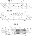
- FIG. 13 shows the prosthetic valve 10 crimped on a balloon catheter.
- the geometry of the struts 31, and junctions 44, 46, and 64 assists in creating enough space in openings 40 in the collapsed configuration to allow portions of the prosthetic leaflets to protrude or bulge outwardly through openings. This allows the prosthetic valve to be crimped to a relatively smaller diameter than if all of the leaflet material were constrained within the crimped frame.
- the frame 12 is configured to reduce, to prevent, or to minimize possible over-expansion of the prosthetic valve at a predetermined balloon pressure, especially at the outflow end portion of the frame, which supports the leaflet structure 14.
- the frame is configured to have relatively larger angles 42a, 42b, 42c, 42d, 42e between struts, as shown in FIG. 5 .
- the larger the angle the greater the force required to open (expand) the frame.
- the angles between the struts of the frame can be selected to limit radial expansion of the frame at a given opening pressure (e.g., inflation pressure of the balloon).
- these angles are at least 110 degrees or greater when the frame is expanded to its functional size, and even more particularly these angles are up to about 120 degrees when the frame is expanded to its functional size.
- the inflow and outflow ends of a frame generally tend to over-expand more so than the middle portion of the frame due to the "dog-boning" effect of the balloon used to expand the prosthetic valve.
- the leaflet structure desirably is secured to the frame 12 below the upper row of struts 32, as best shown in FIG. 1 .
- the leaflet structure is positioned at a level below where over-expansion is likely to occur, thereby protecting the leaflet structure from over-expansion.
- portions of the leaflets protrude longitudinally beyond the outflow end of the frame when the prosthetic valve is crimped if the leaflets are connected too close to the distal end of the frame.
- the delivery catheter on which the crimped prosthetic valve is mounted includes a pushing mechanism or stop member that pushes against or abuts the outflow end of the prosthetic valve (for example, to maintain the position of the crimped prosthetic valve on the delivery catheter), the pushing member or stop member can damage the portions of the exposed leaflets that extend beyond the outflow end of the frame.
- Another benefit of connecting the leaflets at a location spaced away from the outflow end of the frame is that when the prosthetic valve is crimped on a delivery catheter, the outflow end of the frame 12 rather than the leaflets 41 is the proximalmost component of the prosthetic valve 10.
- the delivery catheter includes a pushing mechanism or stop member that pushes against or abuts the outflow end of the prosthetic valve, the pushing mechanism or stop member contacts the outflow end of the frame, and not leaflets 41, so as to avoid damage to the leaflets.
- the openings 36 of the lowermost row of openings in the frame are relatively larger than the openings 38 of the two intermediate rows of openings. This allows the frame, when crimped, to assume an overall tapered shape that tapers from a maximum diameter at the outflow end of the prosthetic valve to a minimum diameter at the inflow end of the prosthetic valve.
- the frame 12 can have a reduced diameter region extending along a portion of the frame adjacent the inflow end of the frame that generally corresponds to the region of the frame covered by the outer skirt 18.
- the reduced diameter region is reduced compared to the diameter of the upper portion of the frame (which is not covered by the outer skirt) such that the outer skirt 18 does not increase the overall crimp profile of the prosthetic valve.
- the frame can expand to the generally cylindrical shape shown in FIG. 4 .
- the frame of a 26-mm prosthetic valve when crimped, had a first diameter of 14 French at the outflow end of the prosthetic valve and a second diameter of 12 French at the inflow end of the prosthetic valve.
- the main functions of the inner skirt 16 are to assist in securing the valvular structure 14 to the frame 12 and to assist in forming a good seal between the prosthetic valve and the native annulus by blocking the flow of blood through the open cells of the frame 12 below the lower edge of the leaflets.
- the inner skirt 16 desirably comprises a tough, tear resistant material such as polyethylene terephthalate (PET), although various other synthetic materials or natural materials (e.g., pericardial tissue) can be used.
- PET polyethylene terephthalate
- the thickness of the skirt desirably is less than about 0.15 mm (about 6 mil), and desirably less than about 0.1 mm (about 4 mil), and even more desirably about 0.05 mm (about 2 mil).
- the skirt 16 can have a variable thickness, for example, the skirt can be thicker at least one of its edges than at its center.
- the skirt 16 can comprise a PET skirt having a thickness of about 0.07 mm at its edges and about 0.06 mm at its center. The thinner skirt can provide for better crimping performances while still providing good sealing.
- the skirt 16 can be secured to the inside of frame 12 via sutures 70, as shown in FIG. 21 .
- Valvular structure 14 can be attached to the skirt via one or more reinforcing strips 72 (which collectively can form a sleeve), for example thin, PET reinforcing strips, discussed below, which enables a secure suturing and protects the pericardial tissue of the leaflet structure from tears.
- Valvular structure 14 can be sandwiched between skirt 16 and the thin PET strips 72 as shown in FIG. 20 .
- Sutures 154 which secure the PET strip and the leaflet structure 14 to skirt 16, can be any suitable suture, such as Ethibond Excel ® PET suture (Johnson & Johnson, New Brunswick, New Jersey).
- Sutures 154 desirably track the curvature of the bottom edge of leaflet structure 14, as described in more detail below.
- Some fabric skirts comprise a weave of warp and weft fibers that extend perpendicularly to each other and with one set of the fibers extending longitudinally between the upper and lower edges of the skirt.
- the metal frame to which such a fabric skirt is secured is radially compressed, the overall axial length of the frame increases.
- a fabric skirt with limited elasticity cannot elongate along with the frame and therefore tends to deform the struts of the frame and to prevent uniform crimping.
- the skirt 16 desirably is woven from a first set of fibers, or yarns or strands, 78 and a second set of fibers, or yarns or strands, 80, both of which are non-perpendicular to the upper edge 82 and the lower edge 84 of the skirt.
- the first set of fibers 78 and the second set of fibers 80 extend at angles of about 45 degrees (e.g., 15-75 degrees or 30-60 degrees) relative to the upper and lower edges 82, 84.
- the skirt 16 can be formed by weaving the fibers at 45 degree angles relative to the upper and lower edges of the fabric.
- the skirt 16 can be diagonally cut (cut on a bias) from a vertically woven fabric (where the fibers extend perpendicularly to the edges of the material) such that the fibers extend at 45 degree angles relative to the cut upper and lower edges of the skirt.
- the opposing short edges 86, 88 of the skirt desirably are non-perpendicular to the upper and lower edges 82, 84.
- the short edges 86, 88 desirably extend at angles of about 45 degrees relative to the upper and lower edges and therefore are aligned with the first set of fibers 78. Therefore the overall general shape of the skirt can be that of a rhomboid or parallelogram.
- FIGS. 14 and 15 show the inner skirt 16 after opposing short edge portions 90, 92 have been sewn together to form the annular shape of the skirt.
- the edge portion 90 can be placed in an overlapping relationship relative to the opposite edge portion 92, and the two edge portions can be sewn together with a diagonally extending suture line 94 that is parallel to short edges 86, 88.
- the upper edge portion of the inner skirt 16 can be formed with a plurality of projections 96 that define an undulating shape that generally follows the shape or contour of the fourth row of struts 28 immediately adjacent the lower ends of axial struts 31. In this manner, as best shown in FIG. 16 , the upper edge of the inner skirt 16 can be tightly secured to struts 28 with sutures 70.
- the inner skirt 16 can also be formed with slits 98 to facilitate attachment of the skirt to the frame. Slits 98 can be dimensioned so as to allow an upper edge portion of the inner skirt 16 to be partially wrapped around struts 28 and to reduce stresses in the skirt during the attachment procedure. For example, in the illustrated embodiment, the inner skirt 16 is placed on the inside of frame 12 and an upper edge portion of the skirt is wrapped around the upper surfaces of struts 28 and secured in place with sutures 70. Wrapping the upper edge portion of the inner skirt 16 around struts 28 in this manner provides for a stronger and more durable attachment of the skirt to the frame. The inner skirt 16 can also be secured to the first, second, and/or third rows of struts 22, 24, and 26, respectively, with sutures 70.
- the skirt can undergo greater elongation in the axial direction (i.e., in a direction from the upper edge 82 to the lower edge 84).
- each cell of the metal frame in the illustrated embodiment includes at least four angled struts that rotate towards the axial direction on crimping (e.g., the angled struts become more aligned with the length of the frame).
- the angled struts of each cell function as a mechanism for rotating the fibers of the skirt in the same direction of the struts, allowing the skirt to elongate along the length of the struts. This allows for greater elongation of the skirt and avoids undesirable deformation of the struts when the prosthetic valve is crimped.
- the spacing between the woven fibers or yarns can be increased to facilitate elongation of the skirt in the axial direction.
- the yarn density can be about 15% to about 30% lower than in a typical PET skirt.
- the yarn spacing of the inner skirt 16 can be from about 60 yarns per cm (about 155 yarns per inch) to about 70 yarns per cm (about 180 yarns per inch), such as about 63 yarns per cm (about 160 yarns per inch), whereas in a typical PET skirt the yarn spacing can be from about 85 yarns per cm (about 217 yarns per inch) to about 97 yarns per cm (about 247 yarns per inch).
- the oblique edges 86, 88 promote a uniform and even distribution of the fabric material along inner circumference of the frame during crimping so as to facilitate uniform crimping to the smallest possible diameter. Additionally, cutting diagonal sutures in a vertical manner may leave loose fringes along the cut edges. The oblique edges 86, 88 help minimize this from occurring.
- the skirt can be formed from woven elastic fibers that can stretch in the axial direction during crimping of the prosthetic valve.
- the warp and weft fibers can run perpendicularly and parallel to the upper and lower edges of the skirt, or alternatively, they can extend at angles between 0 and 90 degrees relative to the upper and lower edges of the skirt, as described above.
- the inner skirt 16 can be sutured to the frame 12 at locations away from the suture line 154 so that the skirt can be more pliable in that area. This configuration can avoid stress concentrations at the suture line 154, which attaches the lower edges of the leaflets to the inner skirt 16.
- the leaflet structure 14 in the illustrated embodiment includes three flexible leaflets 41 (although a greater or a smaller number of leaflets can be used). Additional information regarding the leaflets, as well as additional information regarding skirt material, can be found, for example, in U.S. Patent Application No. 14/704,861, filed May 05, 2015 .
- the leaflets 41 can be secured to one another at their adjacent sides to form commissures 122 of the leaflet structure.
- a plurality of flexible connectors 124 (one of which is shown in FIG. 17 ) can be used to interconnect pairs of adjacent sides of the leaflets and to connect the leaflets to the commissure window frame portions 30 ( FIG. 5 ).
- FIG. 17 shows the adjacent sides of two leaflets 41 interconnected by a flexible connector 124.
- Three leaflets 41 can be secured to each other side-to-side using three flexible connectors 124, as shown in FIG. 18 . Additional information regarding connecting the leaflets to each other, as well as connecting the leaflets to the frame, can be found, for example, in U.S. Patent Application Publication No. 2012/0123529 .
- the inner skirt 16 can be used to assist in suturing the leaflet structure 14 to the frame.
- the inner skirt 16 can have an undulating temporary marking suture to guide the attachment of the lower edges of each leaflet 41.
- the inner skirt 16 itself can be sutured to the struts of the frame 12 using sutures 70, as noted above, before securing the leaflet structure 14 to the skirt 16.
- the struts that intersect the marking suture desirably are not attached to the inner skirt 16. This allows the inner skirt 16 to be more pliable in the areas not secured to the frame and minimizes stress concentrations along the suture line that secures the lower edges of the leaflets to the skirt.
- the fibers 78, 80 of the skirt when the skirt is secured to the frame, the fibers 78, 80 of the skirt (see FIG. 12 ) generally align with the angled struts of the frame to promote uniform crimping and expansion of the frame.
- FIG. 19 shows one specific approach for securing the commissure portions 122 of the leaflet structure 14 to the commissure window frame portions 30 of the frame.
- the flexible connector 124 FIG. 18
- Each upper tab portion 112 is creased lengthwise (vertically) to assume an L-shape having a first portion 142 folded against a surface of the leaflet and a second portion 144 folded against the connector 124.
- the second portion 144 can then be sutured to the connector 124 along a suture line 146.
- the commissure tab assembly is inserted through the commissure window 20 of a corresponding window frame portion 30, and the folds outside of the window frame portion 30 can be sutured to portions 144.
- FIG. 19 also shows that the folded down upper tab portions 112 can form a double layer of leaflet material at the commissures.
- the inner portions 142 of the upper tab portions 112 are positioned flat against layers of the two leaflets 41 forming the commissures, such that each commissure comprises four layers of leaflet material just inside of the window frames 30.
- This four-layered portion of the commissures can be more resistant to bending, or articulating, than the portion of the leaflets 41 just radially inward from the relatively morerigid four-layered portion.
- leaflets 41 This causes the leaflets 41 to articulate primarily at inner edges 143 of the folded-down inner portions 142 in response to blood flowing through the prosthetic valve during operation within the body, as opposed to articulating about or proximal to the axial struts of the window frames 30. Because the leaflets articulate at a location spaced radially inwardly from the window frames 30, the leaflets can avoid contact with and damage from the frame. However, under high forces, the four layered portion of the commissures can splay apart about a longitudinal axis adjacent to the window frame 30, with each first portion 142 folding out against the respective second portion 144. For example, this can occur when the prosthetic valve 10 is compressed and mounted onto a delivery shaft, allowing for a smaller crimped diameter.
- the four-layered portion of the commissures can also splay apart about the longitudinal axis when the balloon catheter is inflated during expansion of the prosthetic valve, which can relieve some of the pressure on the commissures caused by the balloon, reducing potential damage to the commissures during expansion.
- each leaflet 41 can be sutured to the inner skirt 16 along suture line 154 using, for example, Ethibond Excel ® PET thread.
- the sutures can be in-and-out sutures extending through each leaflet 41, the inner skirt 16, and each reinforcing strip 72.
- Each leaflet 41 and respective reinforcing strip 72 can be sewn separately to the inner skirt 16. In this manner, the lower edges of the leaflets are secured to the frame 12 via the inner skirt 16. As shown in FIG.
- the leaflets can be further secured to the skirt with blanket sutures 156 that extend through each reinforcing strip 72, leaflet 41 and the inner skirt 16 while looping around the edges of the reinforcing strips 72 and leaflets 41.
- the blanket sutures 156 can be formed from PTFE suture material.
- FIG. 21 shows a side view of the frame 12, leaflet structure 14 and the inner skirt 16 after securing the leaflet structure 14 and the inner skirt 16 to the frame 12 and the leaflet structure 14 to the inner skirt 16.
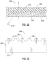
- FIG. 22 shows a cross-sectional view of a patch or section of pericardial tissue 200 that can be formed into an alternative embodiment of an outer skirt.
- the pericardial tissue 200 can be bovine pericardium, porcine pericardium, equine pericardium, kangaroo pericardium, or pericardium from other sources.
- the pericardial tissue 200 has a rough or fibrous layer 202 having a rough surface 206 on one side and a smooth layer 204 having a smooth surface 208 on the opposite side that is relatively smoother and less fibrous than the rough surface 206.
- the tissue 200 can be formed from a section of the parietal pericardial membrane comprising a fibrous parietal layer (the outermost layer of the pericardium) forming the rough layer 202 and a serous parietal layer (the outer serous layer) forming the smooth layer 204.
- the tissue 200 can be harvested and prepared for use in an implant using those techniques and mechanisms known for processing pericardial tissue for heart valve leaflets.
- a process for preparing pericardial tissue for heart valve leaflets typically includes first obtaining a fresh pericardial sac from a source animal, and then cutting the sac open along predetermined anatomical landmarks to obtain a parietal pericardial membrane.
- the parietal pericardial membrane can be flattened and typically cleaned of excess fat and other impurities.
- a window or patch of tissue can be fixed, typically by immersing in an aldehyde to cross-link the tissue. Rough edges of the tissue window can be removed and the tissue can be bio-sorted to result in a tissue section.
- the process of bio-sorting involves visually inspecting the window for unusable areas, and trimming the section therefrom. Further details regarding the process for processing pericardial tissue are disclosed in U.S. Patent Nos. 8,846,390 and 9,358,107 .
- the overall thickness of the parietal pericardial membrane can be reduced by removing a portion of the smooth layer 204 of the pericardial tissue 200, such as by using a laser 210 in a laser milling process, until the pericardial tissue has a desired thickness T.
- the final thickness T after milling is between 50-150 ⁇ m, and more preferably between 100-150 ⁇ m, with 100 ⁇ m being a specific example.
- the pericardial tissue 200 can be milled or otherwise formed to any other thickness T.
- the pericardial tissue 200 has a smooth layer 204, a rough layer 202, a thickness T, and it can be formed into an outer skirt as discussed in connection with figures 23 and 26 below.
- various mechanical devices for skiving or shaving tissue such as razor or planing devices may be used to remove some of the tissue.
- a device having a flat platen over which a planing razor or blade translates may be substituted for the linear laser configuration of FIG. 22 .
- Other physical configurations for creating relative tissue/razor movement are contemplated, such as for instance using a lathe-like razor to smooth the outer surface of the tissue.
- Each of these devices may be automatically or computer-controlled using an optical surface measuring component to control the depth of cut.
- Abrasive tissue removal e.g., sanding or rasping
- a dermatome can be used for skiving or shaving of a portion of the smooth tissue layer 204. Further details regarding the use of a dermatome for removing portions of tissue from pericardial tissue are disclosed in U.S. Patent No. 8,846,390 .
- the thickness of the pericardial tissue 200 can be reduced by removing a portion of the fibrous parietal layer using any of the techniques described above in lieu of or in addition to removing a portion of the serous parietal layer.
- FIGS. 23-24 show various views of an exemplary outer skirt 300 formed from the pericardial tissue 200 of FIG. 22.
- FIG. 23 shows a flattened view of the outer skirt 300 prior to its attachment to a prosthetic heart valve.
- FIG. 24 shows the outer skirt 300 attached to the prosthetic heart valve 10.
- the outer skirt 300 can comprise a first end portion 302 (i.e., the upper end portion as depicted in FIG. 23 ; also the outflow end portion in the illustrated embodiment), a second end portion 304 (i.e., the lower end portion as depicted in FIG. 23 ; also the inflow end portion in the illustrated embodiment), and an intermediate portion 306 disposed between the first and second end portions 302, 304.
- the first end portion 302 of the outer skirt 300 can include a plurality of alternating projections 308 and notches 310, or castellations. In other embodiments, first end portion 302 can be formed without any projections 308 or notches 310 and instead can be substantially straight.
- the outer skirt 300 is attached to the prosthetic heart valve 10.
- the projections 308 of the first end portion 302 can be attached to the inner skirt 16 and/or the frame 12 of the prosthetic heart valve 10 using sutures (as shown) and/or an adhesive.
- the lower end portion 304 can be attached to the inner skirt 16 and/or the frame 12 of the prosthetic heart valve 10 using sutures, an adhesive, or any other suitable attachment means.
- the outer skirt 300 is secured to the frame 12 with the rough surface 206 of the pericardial tissue 200 facing away from the frame 12 and the smooth surface 208 facing the frame 12.
- the rough surface 206 of the pericardium 200 faces the native tissue of the patient.
- the rough surface 206 facing or being in contact with the native tissue can help disturb antegrade blood flow between the outer skirt 300 and the native anatomy of the patient, which can enhance tissue ingrowth and proliferation and help seal any gaps between the prosthetic heart valve 10 and the native anatomy to reduce and/or eliminate perivalvular leakage.
- any contact between the valvular structure 14 and the outer skirt 300 will be with the smooth surface 208 of the pericardium 200, which can be less abrasive than outer skirts made of PET or other fabrics and therefore the outer skirt 300 made from pericardium 200 can help protect the leaflets of the valvular structure 14.
- outer skirt 300 is illustrated as being attached somewhat loosely, that is, with some slack in the intermediate portion 306 of the outer skirt 300, it can also be attached so as to fit more snugly against the outer surface of the frame 12.
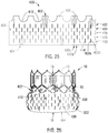
- FIGS. 25-26 show various views of another exemplary outer skirt 400 formed from the pericardial tissue 200 of FIG. 22 .
- FIG. 25 shows a flattened view of the outer skirt 400 prior to its attachment to a prosthetic heart valve.
- FIG. 26 shows the outer skirt 400 attached to the prosthetic heart valve 10.
- the outer skirt 400 can comprise a first end portion 402 (i.e., the upper end portion as depicted in FIG. 25 ), a second end portion 404 (i.e., the lower end portion as depicted in FIG. 25 ), and an intermediate portion 406 disposed between the first and second end portions 402, 404.
- the first end portion 402 of the outer skirt 400 can include a plurality of alternating projections 408 and notches 410, or castellations.
- first end portion 402 can be formed without any projections 408 or notches 410 and instead can be substantially straight.
- the intermediate portion 406 can comprise a plurality of slits or openings 414.
- the slits 414 can be cut or otherwise formed in a longitudinal direction (i.e., an axial direction when the outer skirt 400 is attached to the frame of a prosthetic heart valve).
- the slits 414 can be laser cut or formed by any other means.
- the slits 414 are elongated axially and are arranged in five rows 422, 424, 426, 428, and 430. In other embodiments, the slits 414 can be arranged in more or less than five rows.
- the rows 422, 426, and 430 of slits 414 are circumferentially aligned with each other and are offset from rows 424 and 428 of slits 414, which are circumferentially aligned with each other.
- each slit 414 includes first and second opposing longitudinal sides 432a, 432b, respectively, that are spaced apart from each other to define a permanent open gap therebetween.
- the longitudinal sides 432a, 432b of a slit 414 are in contact with each other (and do not define a permanent open gap therebetween) in the absence of hemodynamic forces, but can move away from each other under hemodynamic forces to allow blood to flow through the skirt via the slits 414.
- the slits 414 are arranged in alternating axially extending columns 420a and 420b.
- the columns 420a can each comprise three slits and the columns 420b can each comprise two slits.
- the slits 414 can be arranged on the outer skirt 400 in any pattern including any number of rows and/or columns containing any number of slits or any other pattern not having a particular number of rows and/or columns.
- the slits 414 can be arranged on the outer skirt 400 in a way that does not have a particular pattern.
- the slits or openings 414 can have any of various other shapes, such as circular, square, rectangular, triangular, or various combinations thereof. In some examples, the slits or openings 414 can be elongated circumferentially or at any other angle with respect to the orientation of the outer skirt 400.
- the outer skirt 400 can be attached to the prosthetic heart valve 10 as previously described.
- the rough layer 202 of the pericardial tissue 200 can help to reduce and/or eliminate perivalvular leakage, as discussed above.
- blood can flow through the slits 414, which can slow the flow of antegrade blood and further enhance blood clotting and tissue ingrowth, which can further help to prevent perivalvular leakage.
- the longitudinal or axial direction of the slits 414 can help reduce stretching or deformation of the outer skirt during passage through a sheath as may be caused by friction between the outer skirt and the inner surface of the sheath.
- outer skirt 400 is illustrated as being attached somewhat loosely, that is, with some slack in the intermediate portion 406 of the outer skirt 400, it can also be attached so as to fit more snugly against the outer surface of the frame 12.
- FIGS. 27-29 show various ways of mounting an outer skirt (e.g., outer skirt 300 or outer skirt 400) to the frame 12 of a prosthetic valve 10.
- reference number 400 is used to designate the outer skirt in FIGS. 27-29 , although it should be understood that the other outer skirts disclosed herein can be mounted to the frame 12 in the same manner.
- the inner skirt 16 comprises an upper edge portion 48 and a lower edge portion 50.
- the upper edge portion 48 of the inner skirt 16 can be secured to the inside of the frame 12 such as via sutures 70 as previously described and as best shown in FIG. 21 .
- the upper edge portion 48 of the inner skirt 16 can be secured to the inside of frame 12 via adhesive and/or ultrasonic welding in addition to or in lieu of sutures 70.
- the upper edge portion 402 of the outer skirt 400 can be secured to the frame 12 with sutures 468.
- the upper edge portions 48 and 402 are shown loosely attached to the frame in FIG. 27 for purposes of illustration, but typically are tightly secured to the frame struts as depicted in FIG. 1 .
- the lower edge portion 50 of the inner skirt 16 can be wrapped around the inflow end portion 15 of the frame 12 and around the lower edge portion 404 of the outer skirt 400.
- the lower edge portion 404 of the outer skirt 400 and the wrapped lower edge portion 50 of the inner skirt 16 can be secured together and/or secured to the frame 12, such as with sutures 470 and/or an adhesive. Wrapping the lower edge portion 50 of the inner skirt 16 around the lower edge portion 404 of the outer skirt 400 can reinforce the lower edge portion 404 and the sutures 470 along the lower edge portion 404.
- the lower edge portions 50 and 404 are shown loosely attached to the frame in FIG. 27 for purposes of illustration, but typically are tightly secured to the frame struts with the sutures 470.
- FIGS. 28-29 show another way of mounting the outer skirt 400 to the frame 12.
- the upper edge portion 402 of the outer skirt 400 can be mounted to the frame 12 with sutures 468 as previously described herein.
- a reinforcing strip 448 having a first edge portion 450 and a second edge portion 452 can be wrapped around the inflow end portion 15 of the frame 12.
- the reinforcing strip 448 can be made of fabric material (e.g., PET) or natural tissue (e.g., pericardial tissue). In some embodiments, the reinforcing strip 448 can be used to secure the cusp portion of each leaflet 41 to the frame, as shown in FIG. 29 .
- an inner skirt 16 also can be mounted inside of the frame 12.
- the reinforcing strip 448 is part of an inner skirt that varies in height around the circumference of the inner skirt with a maximum height at the commissures of the leaflets (such as illustrated in FIG. 27 ) and a minimum height at a location equidistant between two commissures (such as illustrated in FIG. 28 ). Further details of a reinforcing strip that is used to attach the cusp portions of the leaflets to a frame and details of an inner skirt that has a maximum height at the commissures of the leaflets and a minimum height between the commissures are provided in U.S. Provisional Application No. 62/369,678, filed August 1, 2016 .
- the first edge portion 450 of the reinforcing strip 448 can be positioned inside of the frame 12 while the second edge portion 452 can be positioned outside the frame 12.
- the first and second edge portions 450, 452 can be attached to each other and/or to the frame 12, using sutures 470 and/or an adhesive.
- the edge portions 450, 452 are shown loosely attached to the frame in FIGS. 28-29 for purposes of illustration, but typically are tightly secured to the frame.
- the second edge portion 452 of the reinforcing strip 448 can be wrapped around the lower edge portion 404 of the outer skirt 400 such that the lower edge portion 404 is between the frame 12 and the reinforcing strip 448.
- the lower edge portion 404 of the outer skirt 400 can be secured to the frame 12 and the second edge portion 452 of the reinforcing strip 448 with the sutures 470 and/or an adhesive.
- the lower cusp portion of each leaflet 41 can be secured between the frame 12 and the first edge portion 450 of the reinforcing strip 448 with sutures (e.g., with sutures 472) and/or an adhesive.
- the outer skirt 400 is shown protruding inwardly through the frame 12, which may occur during cycling and/or when the frame 12 is crimped to its radially collapsed configuration.
- the outer skirt 400 may contact one of the leaflets 41.
- any contact between any of the leaflets 41 and the outer skirt 400 will be with the smooth surface 208 of the pericardial tissue 200 that forms the outer skirt 400, thereby preventing or minimizing abrasion of the leaflets 41.
- FIG. 30 shows a prosthetic heart valve 10 having an outer skirt 500, according to another embodiment.
- the outer skirt 500 in the illustrated embodiment comprises a main body or layer 502 of pericardial tissue and a plurality of strips 504 of material mounted on the outer surface of the main body 502.
- the main body 502 can be the outer skirt 300 or the outer skirt 400.
- the strips 504 desirably are made from a substantially non-elastic and nonstretchable material.
- the strips 504 can be sutures, pieces of woven fabric (e.g., PET strips), pieces of non-woven fabric, or other types of fibrous material.
- the strips 504 are arranged to form a repeating U-shaped pattern around the main body 502.
- the strips 504 can be arranged in any other pattern (e.g., the strips 504 can extend parallel to the longitudinal axis of the prosthetic valve).
- the strips 502 can facilitate passage of the prosthetic valve through an introducer sheath by reducing contact between the pericardial tissue forming the main body 502 and the inner surface of the sheath and by resisting stretching of the pericardial tissue caused by frictional contact with the inner surface of the sheath.
- the strips 504 when formed from an absorbent material, such as fabric, the strips 504 can absorb blood to help enhance blood clotting and tissue ingrowth to further reduce perivalvular leakage.
- outer skirt 500 is illustrated as being attached somewhat loosely, that is, with some slack in the main body 502 of the outer skirt 300, it can also be attached so as to fit more snugly against the outer surface of the frame 12.
- the prosthetic valve 10 can be configured for and mounted on a suitable delivery apparatus for implantation in a subject.
- a suitable delivery apparatus for implantation in a subject.
- catheter-based delivery apparatuses can be used; a non-limiting example of a suitable catheter-based delivery apparatus includes that disclosed in U.S. Patent Application Publication Nos. 2013/0030519 and 2012/0123529 .
- the prosthetic valve 10 including the outer skirt 400 can be crimped on an elongated shaft 180 of a delivery apparatus, as best shown in FIG. 13 .
- the prosthetic valve, together with the delivery apparatus, can form a delivery assembly for implanting the prosthetic valve 10 in a patient's body.
- the shaft 180 comprises an inflatable balloon 182 for expanding the prosthetic valve within the body. With the balloon 182 deflated, the prosthetic valve 10 can then be percutaneously delivered to a desired implantation location (e.g., a native aortic valve region). Once the prosthetic valve 10 is delivered to the implantation site (e.g., the native aortic valve) inside the body, the prosthetic valve 10 can be radially expanded to its functional state by inflating the balloon 182.
- a desired implantation location e.g., a native aortic valve region
- a self-expanding prosthetic valve 10 can be crimped to a radially collapsed configuration and restrained in the collapsed configuration by inserting the prosthetic valve 10, including the outer skirt 400, into a sheath or equivalent mechanism of a delivery catheter.
- the prosthetic valve 10 can then be percutaneously delivered to a desired implantation location. Once inside the body, the prosthetic valve 10 can be advanced from the delivery sheath, which allows the prosthetic valve to expand to its functional state.
- FIGS. 31-33 and 36 show various implantation positions for a prosthetic heart valve 10, including implantation within a dock or anchor placed inside the patient's body prior to valve implantation.
- FIG. 31 shows the prosthetic heart valve 10 implanted in the native aortic valve of a patient.
- FIG. 32 shows the prosthetic heart valve 10 implanted in the pulmonary artery of a patient for replacing or enhancing the function of a diseased pulmonary valve.
- the prosthetic valve 10 can be implanted within a radially expandable outer docking device 600.
- the docking device 600 can comprise a radially expandable and compressible annular stent 602 and a sealing member 604 that covers all or a portion of the stent and can extend across the inner surface and/or outer surface of the stent.
- the docking device 600 is configured to engage the inner wall of the pulmonary artery and can accommodate variations in patient anatomy.
- the docking device 600 also can compensate for the expanded prosthetic heart valve 10 being much smaller than vessel in which it is placed.
- the docking device 600 also can be used to support a prosthetic valve in other areas of the patient's anatomy, such as, the inferior vena cava, superior vena cava, or the aorta. Further details of the docking device 600 and methods for implanting the docking device and a prosthetic valve are disclosed, for example, in co-pending U.S. Application No. 15/422,354, filed February 1, 2017 .
- FIG. 33 shows the prosthetic heart valve 10 implanted in the native mitral valve of a patient using a docking device in the form of a helical anchor 700.
- the helical anchor 700 can include one or more coils 702 deployed in left atrium and one or more coils 704 deployed in the left ventricle and radially outside of the native mitral valve leaflets 706.
- the native leaflets are compressed or pinched between the prosthetic valve 10 and the anchor 700 to retain the prosthetic valve in place.
- Further details of the helical anchor 700 and methods for implanting the anchor and a prosthetic valve are disclosed, for example, in co-pending U.S. Application No. 62/395,940, filed September 16, 2016 .
- FIGS. 34 and 35 show a docking device 800 for a prosthetic heart valve, according to another embodiment.
- the docking device 800 can include a radially expandable and compressible frame 802 having an outer portion 804, an inner portion 806 disposed coaxially within one end portion of the outer portion 804, and a curved transition portion 808 extending between and connecting the inner portion 806 and the outer portion 804.
- the docking device 800 can further include a sealing member 810 extending over the inner surface of the inner portion 806, a portion of the outer surface of the outer portion 804 adjacent the inner portion 806, and the transition portion 808.
- FIG. 36 shows the docking device 800 implanted in a vessel 820, which can be, for example, the inferior vena cava, superior vena cava, or the ascending aorta.
- a prosthetic valve 10 can be deployed within the inner portion 806 of the docking device 800. Similar to the docking device 600, the docking device 800 can compensate for the expanded prosthetic heart valve 10 being much smaller than vessel in which it is placed.
- the docking device 800 is particularly suited for implanting a prosthetic valve in the inferior vena cava for replacing or enhancing the function of the native tricuspid valve. Further details of the docking device 800 and methods for implanting the docking device and a prosthetic valve are disclosed, for example, in co-pending U.S. Application No. 16/034,794 ( US 2019/0000615 A1), filed July 13, 2018 .
- the disclosed valves can be implanted in any of the native annuluses of the heart (e.g., the pulmonary, mitral, and tricuspid annuluses), and can be used with any of various approaches (e.g., retrograde, antegrade, transseptal, transventricular, transatrial, etc.).
- the disclosed prostheses can also be implanted in other lumens of the body.
- the delivery assembly embodiments described herein can be adapted to deliver and implant various other prosthetic devices such as stents and/or other prosthetic repair devices.
- an outer skirt for a prosthetic heart valve can include one or more features disclosed with respect to skirt 18, skirt 300, skirt 400, and/or skirt 500.
- proximal refers to a position, direction, or portion of a device that is closer to the user and further away from the implantation site.
- distal refers to a position, direction, or portion of a device that is further away from the user and closer to the implantation site.
- proximal motion of a device is motion of the device toward the user
- distal motion of the device is motion of the device away from the user.
- longitudinal and axial refer to an axis extending in the proximal and distal directions, unless otherwise expressly defined.
- Coupled and “associated” generally mean physically coupled or linked and does not exclude the presence of intermediate elements between the coupled or associated items absent specific contrary language.
Description
- The present disclosure relates to implantable, expandable prosthetic devices and to methods and apparatuses for such prosthetic devices.
- The human heart can suffer from various valvular diseases. These valvular diseases can result in significant malfunctioning of the heart and ultimately require replacement of the native valve with an artificial valve. There are a number of known artificial valves and a number of known methods of implanting these artificial valves in humans. Because of the drawbacks associated with conventional open-heart surgery, percutaneous and minimallyinvasive surgical approaches are garnering intense attention. In one technique, a prosthetic valve is configured to be implanted in a much less invasive procedure by way of catheterization. For example, collapsible transcatheter prosthetic heart valves can be crimped to a compressed state and percutaneously introduced in the compressed state on a catheter and expanded to a functional size at the desired position by balloon inflation or by utilization of a self-expanding frame or stent.
- A prosthetic valve for use in such a procedure can include a radially collapsible and expandable frame to which leaflets of the prosthetic valve can be coupled, and which can be percutaneously introduced in a collapsed configuration on a catheter and expanded in the desired position by balloon inflation or by utilization of a self-expanding frame or stent. A challenge in catheter-implanted prosthetic valves is control of perivalvular leakage around the valve, which can occur for a period of time following initial implantation. An additional challenge includes the process of crimping such a prosthetic valve to a profile suitable for percutaneous delivery to a subject.
-
WO 2015/152980 discloses a prosthetic heart valve including a collapsible and expandable stent, a cuff attached to the stent, and a sealing member attached to the cuff and extending from a proximal end of the cuff to a free edge. The sealing member comprises pericardial tissue but does not define that the pericardial tissue has a fibrous parietal layer as first surface and a serous parietal layer as second surface. - Gauvin et al. ("A comparative study of bovine and porcine pericardium to highlight their potential advantages to manufacture percutaneous cardiovascular implants", Journal of biomaterials applications, vol. 28, no. 4, 2012-11-30, pages 552-565) relates to a comparative study of bovine and porcine pericardium in the context of percutaneous cardiovascular implants. It reports on their general suitability for use in the manufacture of percutaneous heart valves.
- The foregoing and other objects, features, and advantages of the disclosure will become more apparent from the following detailed description, which proceeds with reference to the accompanying figures.
- The present invention is defined in the appended claims. According to the invention as defined in
claim 1, an implantable prosthetic valve comprises an annular frame, a leaflet structure positioned within the frame, and an outer skirt positioned around an outer surface of the frame. The annular frame comprises an inflow end and an outflow end and can be radially collapsible and expandable between a radially collapsed configuration and a radially expanded configuration. The outer skirt comprises pericardial tissue having a fibrous parietal layer defining a first surface of the outer skirt and a serous parietal layer defining a second surface of the outer skirt. The outer skirt is positioned such that the first surface is facing away from the frame and the second surface is facing towards the frame. - In some embodiments, the outer skirt can comprise bovine pericardial tissue.
- In some embodiments, the outer skirt can be laser milled to reduce its thickness.
- In some embodiments, the thickness of the outer skirt can be between 50 µm and 150 µm.
- In some embodiments, the outer skirt can comprise a plurality of openings or slits.
- In some embodiments, at least one of the openings or slits can be elongated in an axial direction.
- In some embodiments, the outer skirt can comprise an outflow edge portion and an inflow edge portion. The outflow edge portion can comprise a plurality of alternating projections and notches and the projections can be secured to the frame and the notches can be not directly secured to the frame.
- In some embodiments, the prosthetic valve can further comprise a reinforcing strip that wraps around the inflow end of the frame such that a first end portion of the reinforcing strip extends at least partially along an inner surface of the frame and is secured thereto, and a second end portion of the reinforcing strip extends at least partially along an outer surface of the outer skirt and is secured thereto.
- In some embodiments, the outer skirt can be secured to the frame with sutures.
- In some embodiments, the prosthetic valve can further comprise an inner skirt positioned around an inner surface of the frame and secured thereto.
- In some embodiments, the inner skirt can comprise an outflow edge portion secured to the frame and an inflow edge portion that wraps around the inflow end of the frame and the inflow end of the outer skirt. In such embodiments, the inflow end portion can extend at least partially along an outer surface of the outer skirt and can be secured thereto.
- In some embodiments, the prosthetic valve can further comprise one or more strips positioned around an outer surface of the outer skirt and secured thereto.
- In some embodiments, the strips can comprise a fabric material.
- In another embodiment, a method of manufacturing a prosthetic heart valve can comprise providing a piece of pericardial tissue comprising a fibrous parietal layer and a serous parietal layer, reducing the thickness of the piece of pericardial tissue by removing a portion of the serous parietal layer, and positioning the pericardial tissue around an outer surface of a frame of the prosthetic heart valve and securing it thereto. The fibrous parietal layer can define a first surface of the tissue and the serous parietal layer can define a second surface of the tissue. The pericardial tissue can be positioned around the frame such that the first surface is facing away from the frame and the second surface is facing towards the frame.
- In some embodiments, the pericardial tissue can have a thickness between 50 µm and 100 µm.
- In some embodiments, the act of reducing the thickness of the piece of pericardial tissue can comprise laser milling the serous parietal layer.
- In some embodiments, the method can further comprise forming slits or openings in the piece of pericardial tissue before positioning it on the frame.
- In some embodiments, the method can further comprise connecting a plurality of prosthetic leaflets to the inside of the frame.
- In another embodiment a method of implanting a prosthetic heart valve can comprise inserting a distal end portion of a delivery apparatus and a prosthetic heart valve coupled to the distal end portion of the delivery apparatus into a patient's body, positioning the prosthetic heart valve adjacent a native valve of the patient's heart, and radially expanding the prosthetic heart valve. The prosthetic heart valve can comprise an annular frame, a leaflet structure positioned within the frame and secured thereto, and an outer skirt positioned around an outer surface of the frame. The annular frame can comprise an inflow end and an outflow end and can be radially collapsible and expandable between a radially collapsed configuration and a radially expanded configuration. The outer skirt can comprise pericardial tissue having a fibrous parietal layer defining an outer surface of the skirt and a serous parietal layer defining an inner surface of the skirt. The prosthetic heart valve can be expanded such that the fibrous parietal layer can contact the surrounding native tissue.
- In some embodiments, the outer skirt can comprise a plurality of slits or openings such that antegrade blood can flow through the slits or openings.
-
-
FIGS. 1-3 show an exemplary embodiment of a prosthetic heart valve. -
FIGS. 4-10 show an exemplary frame of the prosthetic heart valve ofFIG. 1 . -
FIGS. 11-12 show an exemplary inner skirt of the prosthetic heart valve ofFIG. 1 . -
FIG. 13 shows the prosthetic heart valve ofFIG. 1 in a collapsed configuration and mounted on an exemplary balloon catheter. -
FIGS. 14-16 show the assembly of the inner skirt ofFIG. 11 with the frame ofFIG. 4 . -
FIGS. 17-18 show the assembly of an exemplary leaflet structure. -
FIG. 19 shows the assembly of commissure portions of the leaflet structure with window frame portions of the frame. -
FIGS. 20-21 show the assembly of the leaflet structure with the inner skirt along a lower edge of the leaflets. -
FIG. 22 shows a cross-sectional view of pericardial tissue that can be formed into an outer skirt. -
FIG. 23 shows an exemplary outer skirt formed from the pericardial tissue ofFIG. 22 . -
FIG. 24 shows an exemplary prosthetic heart valve using the outer skirt ofFIG. 23 . -
FIG. 25 shows another exemplary outer skirt formed from the pericardial tissue ofFIG. 22 . -
FIG. 26 shows another exemplary prosthetic heart valve using the outer skirt ofFIG. 25 . -
FIGS. 27-29 show various cross-sectional views of an exemplary embodiment of a prosthetic heart valve. -
FIG. 30 shows another exemplary prosthetic heart valve. -
FIG. 31 shows an exemplary prosthetic heart valve implanted in the native aortic valve of a patient. -
FIG. 32 shows an exemplary prosthetic heart valve and docking device implanted in the pulmonary artery of a patient. -
FIG. 33 shows an exemplary prosthetic heart valve and docking device implanted in the native mitral valve of a patient. -
FIGS. 34-35 show an alternative embodiment of a docking device for a prosthetic valve. -
FIG. 36 shows an exemplary prosthetic heart valve and the docking device ofFIGS. 34-35 implanted in the inferior vena cava of a patient. -
FIGS. 1-3 show various views of aprosthetic heart valve 10, according to one embodiment. The illustrated prosthetic valve is adapted to be implanted in the native aortic annulus, although in other embodiments it can be adapted to be implanted in the other native annuluses of the heart (e.g., the pulmonary, mitral, and tricuspid valves). The prosthetic valve can also be adapted to be implanted in other tubular organs or passageways in the body. Theprosthetic valve 10 can have four main components: a stent orframe 12, avalvular structure 14, aninner skirt 16, and a perivalvular sealing means or sealing member. Theprosthetic valve 10 can have aninflow end portion 15, anintermediate portion 17, and anoutflow end portion 19. In the illustrated embodiment, the perivalvular sealing means comprises an outer skirt 18 (which can also be referred to as an outer sealing member). - The
valvular structure 14 can comprise threeleaflets 41, collectively forming a leaflet structure, which can be arranged to collapse in a tricuspid arrangement, as best shown inFIG. 2 . The lower edge ofleaflet structure 14 desirably has an undulating, curved scalloped shape (suture line 154 shown inFIG. 21 tracks the scalloped shape of the leaflet structure). By forming the leaflets with this scalloped geometry, stresses on the leaflets are reduced, which in turn improves durability of the prosthetic valve. Moreover, by virtue of the scalloped shape, folds and ripples at the belly of each leaflet (the central region of each leaflet), which can cause early calcification in those areas, can be eliminated or at least minimized. The scalloped geometry also reduces the amount of tissue material used to form leaflet structure, thereby allowing a smaller, more even crimped profile at the inflow end of the prosthetic valve. Theleaflets 41 can be formed of pericardial tissue (e.g., bovine pericardial tissue), biocompatible synthetic materials, or various other suitable natural or synthetic materials as known in the art and described inU.S. Patent No. 6,730,118 . - The
bare frame 12 is shown inFIG. 4 . Theframe 12 can be formed with a plurality of circumferentially spaced slots, or commissure windows, 20 (three in the illustrated embodiment) that are adapted to connect the commissures of thevalvular structure 14 to the frame, as described in greater detail below. Theframe 12 can be made of any of various suitable plastically-expandable materials (e.g., stainless steel, etc.) or self-expanding materials (e.g., nickel titanium alloy (NiTi), such as nitinol). When constructed of a plastically-expandable material, the frame 12 (and thus the prosthetic valve 10) can be crimped to a radially collapsed configuration on a delivery catheter and then expanded inside a patient by an inflatable balloon or equivalent expansion mechanism. When constructed of a self-expandable material, the frame 12 (and thus the prosthetic valve 10) can be crimped to a radially collapsed configuration and restrained in the collapsed configuration by insertion into a sheath or equivalent mechanism of a delivery catheter. Once inside the body, the prosthetic valve can be advanced from the delivery sheath, which allows the prosthetic valve to expand to its functional size. - Suitable plastically-expandable materials that can be used to form the
frame 12 include, without limitation, stainless steel, a biocompatible, high-strength alloys (e.g., a cobalt-chromium or a nickel-cobalt-chromium alloys), polymers, or combinations thereof. In particular embodiments,frame 12 is made of a nickel-cobalt-chromium-molybdenum alloy, such as MP35N® alloy (SPS Technologies, Jenkintown, Pennsylvania), which is equivalent to UNS R30035 alloy (covered by ASTM F562-02). MP35N® alloy/UNS R30035 alloy comprises 35% nickel, 35% cobalt, 20% chromium, and 10% molybdenum, by weight. When MP35N® alloy is used as the frame material, as compared to stainless steel, less material is needed to achieve the same or better performance in radial and crush force resistance, fatigue resistances, and corrosion resistance. Moreover, since less material is required, the crimped profile of the frame can be reduced, thereby providing a lower profile prosthetic valve assembly for percutaneous delivery to the treatment location in the body. - Referring to
FIGS. 4 and 5 , theframe 12 in the illustrated embodiment comprises a first, lower row I ofangled struts 22 arranged end-to-end and extending circumferentially at the inflow end of the frame; a second row II of circumferentially extending, angled struts 24; a third row III of circumferentially extending, angled struts 26; a fourth row IV of circumferentially extending, angled struts 28; and a fifth row V of circumferentially extending, angled struts 32 at the outflow end of the frame. A plurality of substantially straight axially extendingstruts 34 can be used to interconnect thestruts 22 of the first row I with thestruts 24 of the second row II. The fifth row V ofangled struts 32 are connected to the fourth row IV ofangled struts 28 by a plurality of axially extending window frame portions 30 (which define the commissure windows 20) and a plurality of axially extendingstruts 31. Eachaxial strut 31 and eachframe portion 30 extends from a location defined by the convergence of the lower ends of twoangled struts 32 to another location defined by the convergence of the upper ends of twoangled struts 28.FIGS. 6, 7, 8 ,9, and 10 are enlarged views of the portions of theframe 12 identified by letters A, B, C, D, and E, respectively, inFIG. 5 . - Each commissure
window frame portion 30 connects to a respective commissure of theleaflet structure 14. As can be seen eachframe portion 30 is secured at its upper and lower ends to the adjacent rows of struts to provide a robust configuration that enhances fatigue resistance under cyclic loading of the prosthetic valve compared to cantilevered struts for supporting the commissures of the leaflet structure. This configuration enables a reduction in the frame wall thickness to achieve a smaller crimped diameter of the prosthetic valve. In particular embodiments, the thickness T of the frame 12 (FIG. 4 ) measured between the inner diameter and outer diameter is about 0.48 mm or less. - The struts and frame portions of the frame collectively define a plurality of open cells of the frame. At the inflow end of the
frame 12, struts 22, struts 24, and struts 34 define a lower row ofcells defining openings 36. The second, third, and fourth rows ofstruts cells defining openings 38. The fourth and fifth rows ofstruts frame portions 30 and struts 31, define an upper row of cells defining openings 40. The openings 40 are relatively large and are sized to allow portions of theleaflet structure 14 to protrude, or bulge, into and/or through the openings 40 when theframe 12 is crimped in order to minimize the crimping profile. - As best shown in
FIG. 7 , the lower end of thestrut 31 is connected to twostruts 28 at a node orjunction 44, and the upper end of thestrut 31 is connected to twostruts 32 at a node orjunction 46. Thestrut 31 can have a thickness S1 that is less than the thicknesses S2 of thejunctions junctions junctions 64, prevent full closure of openings 40.FIG. 13 shows theprosthetic valve 10 crimped on a balloon catheter. As can be seen, the geometry of thestruts 31, andjunctions - The
frame 12 is configured to reduce, to prevent, or to minimize possible over-expansion of the prosthetic valve at a predetermined balloon pressure, especially at the outflow end portion of the frame, which supports theleaflet structure 14. In one aspect, the frame is configured to have relativelylarger angles FIG. 5 . The larger the angle, the greater the force required to open (expand) the frame. As such, the angles between the struts of the frame can be selected to limit radial expansion of the frame at a given opening pressure (e.g., inflation pressure of the balloon). In particular embodiments, these angles are at least 110 degrees or greater when the frame is expanded to its functional size, and even more particularly these angles are up to about 120 degrees when the frame is expanded to its functional size. - In addition, the inflow and outflow ends of a frame generally tend to over-expand more so than the middle portion of the frame due to the "dog-boning" effect of the balloon used to expand the prosthetic valve. To protect against over-expansion of the
leaflet structure 14, the leaflet structure desirably is secured to theframe 12 below the upper row ofstruts 32, as best shown inFIG. 1 . Thus, in the event that the outflow end of the frame is overexpanded, the leaflet structure is positioned at a level below where over-expansion is likely to occur, thereby protecting the leaflet structure from over-expansion. - In one type of prosthetic valve construction, portions of the leaflets protrude longitudinally beyond the outflow end of the frame when the prosthetic valve is crimped if the leaflets are connected too close to the distal end of the frame. If the delivery catheter on which the crimped prosthetic valve is mounted includes a pushing mechanism or stop member that pushes against or abuts the outflow end of the prosthetic valve (for example, to maintain the position of the crimped prosthetic valve on the delivery catheter), the pushing member or stop member can damage the portions of the exposed leaflets that extend beyond the outflow end of the frame. Another benefit of connecting the leaflets at a location spaced away from the outflow end of the frame is that when the prosthetic valve is crimped on a delivery catheter, the outflow end of the
frame 12 rather than theleaflets 41 is the proximalmost component of theprosthetic valve 10. As such, if the delivery catheter includes a pushing mechanism or stop member that pushes against or abuts the outflow end of the prosthetic valve, the pushing mechanism or stop member contacts the outflow end of the frame, and notleaflets 41, so as to avoid damage to the leaflets. - Also, as can be seen in
FIG. 5 , theopenings 36 of the lowermost row of openings in the frame are relatively larger than theopenings 38 of the two intermediate rows of openings. This allows the frame, when crimped, to assume an overall tapered shape that tapers from a maximum diameter at the outflow end of the prosthetic valve to a minimum diameter at the inflow end of the prosthetic valve. When crimped, theframe 12 can have a reduced diameter region extending along a portion of the frame adjacent the inflow end of the frame that generally corresponds to the region of the frame covered by theouter skirt 18. In some embodiments, the reduced diameter region is reduced compared to the diameter of the upper portion of the frame (which is not covered by the outer skirt) such that theouter skirt 18 does not increase the overall crimp profile of the prosthetic valve. When the prosthetic valve is deployed, the frame can expand to the generally cylindrical shape shown inFIG. 4 . In one example, the frame of a 26-mm prosthetic valve, when crimped, had a first diameter of 14 French at the outflow end of the prosthetic valve and a second diameter of 12 French at the inflow end of the prosthetic valve. - The main functions of the
inner skirt 16 are to assist in securing thevalvular structure 14 to theframe 12 and to assist in forming a good seal between the prosthetic valve and the native annulus by blocking the flow of blood through the open cells of theframe 12 below the lower edge of the leaflets. Theinner skirt 16 desirably comprises a tough, tear resistant material such as polyethylene terephthalate (PET), although various other synthetic materials or natural materials (e.g., pericardial tissue) can be used. The thickness of the skirt desirably is less than about 0.15 mm (about 6 mil), and desirably less than about 0.1 mm (about 4 mil), and even more desirably about 0.05 mm (about 2 mil). In particular embodiments, theskirt 16 can have a variable thickness, for example, the skirt can be thicker at least one of its edges than at its center. In one implementation, theskirt 16 can comprise a PET skirt having a thickness of about 0.07 mm at its edges and about 0.06 mm at its center. The thinner skirt can provide for better crimping performances while still providing good sealing. - The
skirt 16 can be secured to the inside offrame 12 viasutures 70, as shown inFIG. 21 .Valvular structure 14 can be attached to the skirt via one or more reinforcing strips 72 (which collectively can form a sleeve), for example thin, PET reinforcing strips, discussed below, which enables a secure suturing and protects the pericardial tissue of the leaflet structure from tears.Valvular structure 14 can be sandwiched betweenskirt 16 and the thin PET strips 72 as shown inFIG. 20 .Sutures 154, which secure the PET strip and theleaflet structure 14 to skirt 16, can be any suitable suture, such as Ethibond Excel® PET suture (Johnson & Johnson, New Brunswick, New Jersey).Sutures 154 desirably track the curvature of the bottom edge ofleaflet structure 14, as described in more detail below. - Some fabric skirts comprise a weave of warp and weft fibers that extend perpendicularly to each other and with one set of the fibers extending longitudinally between the upper and lower edges of the skirt. When the metal frame to which such a fabric skirt is secured is radially compressed, the overall axial length of the frame increases. However, a fabric skirt with limited elasticity cannot elongate along with the frame and therefore tends to deform the struts of the frame and to prevent uniform crimping.
- Referring to
FIG. 12 , in one embodiment, theskirt 16 desirably is woven from a first set of fibers, or yarns or strands, 78 and a second set of fibers, or yarns or strands, 80, both of which are non-perpendicular to theupper edge 82 and thelower edge 84 of the skirt. In particular embodiments, the first set offibers 78 and the second set offibers 80 extend at angles of about 45 degrees (e.g., 15-75 degrees or 30-60 degrees) relative to the upper andlower edges skirt 16 can be formed by weaving the fibers at 45 degree angles relative to the upper and lower edges of the fabric. Alternatively, theskirt 16 can be diagonally cut (cut on a bias) from a vertically woven fabric (where the fibers extend perpendicularly to the edges of the material) such that the fibers extend at 45 degree angles relative to the cut upper and lower edges of the skirt. As further shown inFIG. 12 , the opposingshort edges lower edges short edges fibers 78. Therefore the overall general shape of the skirt can be that of a rhomboid or parallelogram. -
FIGS. 14 and 15 show theinner skirt 16 after opposingshort edge portions edge portion 90 can be placed in an overlapping relationship relative to theopposite edge portion 92, and the two edge portions can be sewn together with a diagonally extendingsuture line 94 that is parallel toshort edges inner skirt 16 can be formed with a plurality ofprojections 96 that define an undulating shape that generally follows the shape or contour of the fourth row ofstruts 28 immediately adjacent the lower ends ofaxial struts 31. In this manner, as best shown inFIG. 16 , the upper edge of theinner skirt 16 can be tightly secured tostruts 28 withsutures 70. Theinner skirt 16 can also be formed withslits 98 to facilitate attachment of the skirt to the frame.Slits 98 can be dimensioned so as to allow an upper edge portion of theinner skirt 16 to be partially wrapped around struts 28 and to reduce stresses in the skirt during the attachment procedure. For example, in the illustrated embodiment, theinner skirt 16 is placed on the inside offrame 12 and an upper edge portion of the skirt is wrapped around the upper surfaces ofstruts 28 and secured in place withsutures 70. Wrapping the upper edge portion of theinner skirt 16 around struts 28 in this manner provides for a stronger and more durable attachment of the skirt to the frame. Theinner skirt 16 can also be secured to the first, second, and/or third rows ofstruts sutures 70. - Referring again to
FIG. 12 , due to the angled orientation of the fibers relative to the upper and lower edges in this embodiment, the skirt can undergo greater elongation in the axial direction (i.e., in a direction from theupper edge 82 to the lower edge 84). - Thus, when the
metal frame 12 is crimped (as shown inFIG. 13 ), theinner skirt 16 can elongate in the axial direction along with the frame and therefore provide a more uniform and predictable crimping profile. Each cell of the metal frame in the illustrated embodiment includes at least four angled struts that rotate towards the axial direction on crimping (e.g., the angled struts become more aligned with the length of the frame). The angled struts of each cell function as a mechanism for rotating the fibers of the skirt in the same direction of the struts, allowing the skirt to elongate along the length of the struts. This allows for greater elongation of the skirt and avoids undesirable deformation of the struts when the prosthetic valve is crimped. - In addition, the spacing between the woven fibers or yarns can be increased to facilitate elongation of the skirt in the axial direction. For example, for a PET
inner skirt 16 formed from 20-denier yarn, the yarn density can be about 15% to about 30% lower than in a typical PET skirt. In some examples, the yarn spacing of theinner skirt 16 can be from about 60 yarns per cm (about 155 yarns per inch) to about 70 yarns per cm (about 180 yarns per inch), such as about 63 yarns per cm (about 160 yarns per inch), whereas in a typical PET skirt the yarn spacing can be from about 85 yarns per cm (about 217 yarns per inch) to about 97 yarns per cm (about 247 yarns per inch). The oblique edges 86, 88 promote a uniform and even distribution of the fabric material along inner circumference of the frame during crimping so as to facilitate uniform crimping to the smallest possible diameter. Additionally, cutting diagonal sutures in a vertical manner may leave loose fringes along the cut edges. The oblique edges 86, 88 help minimize this from occurring. - In alternative embodiments, the skirt can be formed from woven elastic fibers that can stretch in the axial direction during crimping of the prosthetic valve. The warp and weft fibers can run perpendicularly and parallel to the upper and lower edges of the skirt, or alternatively, they can extend at angles between 0 and 90 degrees relative to the upper and lower edges of the skirt, as described above.
- The
inner skirt 16 can be sutured to theframe 12 at locations away from thesuture line 154 so that the skirt can be more pliable in that area. This configuration can avoid stress concentrations at thesuture line 154, which attaches the lower edges of the leaflets to theinner skirt 16. - As noted above, the
leaflet structure 14 in the illustrated embodiment includes three flexible leaflets 41 (although a greater or a smaller number of leaflets can be used). Additional information regarding the leaflets, as well as additional information regarding skirt material, can be found, for example, inU.S. Patent Application No. 14/704,861, filed May 05, 2015 - The
leaflets 41 can be secured to one another at their adjacent sides to formcommissures 122 of the leaflet structure. A plurality of flexible connectors 124 (one of which is shown inFIG. 17 ) can be used to interconnect pairs of adjacent sides of the leaflets and to connect the leaflets to the commissure window frame portions 30 (FIG. 5 ). -
FIG. 17 shows the adjacent sides of twoleaflets 41 interconnected by aflexible connector 124. Threeleaflets 41 can be secured to each other side-to-side using threeflexible connectors 124, as shown inFIG. 18 . Additional information regarding connecting the leaflets to each other, as well as connecting the leaflets to the frame, can be found, for example, inU.S. Patent Application Publication No. 2012/0123529 . - As noted above, the
inner skirt 16 can be used to assist in suturing theleaflet structure 14 to the frame. Theinner skirt 16 can have an undulating temporary marking suture to guide the attachment of the lower edges of eachleaflet 41. Theinner skirt 16 itself can be sutured to the struts of theframe 12 usingsutures 70, as noted above, before securing theleaflet structure 14 to theskirt 16. The struts that intersect the marking suture desirably are not attached to theinner skirt 16. This allows theinner skirt 16 to be more pliable in the areas not secured to the frame and minimizes stress concentrations along the suture line that secures the lower edges of the leaflets to the skirt. As noted above, when the skirt is secured to the frame, thefibers FIG. 12 ) generally align with the angled struts of the frame to promote uniform crimping and expansion of the frame. -
FIG. 19 shows one specific approach for securing thecommissure portions 122 of theleaflet structure 14 to the commissurewindow frame portions 30 of the frame. In this approach, the flexible connector 124 (FIG. 18 ) securing two adjacent sides of two leaflets is folded widthwise and theupper tab portions 112 are folded downwardly against the flexible connector. Eachupper tab portion 112 is creased lengthwise (vertically) to assume an L-shape having afirst portion 142 folded against a surface of the leaflet and asecond portion 144 folded against theconnector 124. Thesecond portion 144 can then be sutured to theconnector 124 along asuture line 146. Next, the commissure tab assembly is inserted through thecommissure window 20 of a correspondingwindow frame portion 30, and the folds outside of thewindow frame portion 30 can be sutured toportions 144. -
FIG. 19 also shows that the folded downupper tab portions 112 can form a double layer of leaflet material at the commissures. Theinner portions 142 of theupper tab portions 112 are positioned flat against layers of the twoleaflets 41 forming the commissures, such that each commissure comprises four layers of leaflet material just inside of the window frames 30. This four-layered portion of the commissures can be more resistant to bending, or articulating, than the portion of theleaflets 41 just radially inward from the relatively morerigid four-layered portion. This causes theleaflets 41 to articulate primarily atinner edges 143 of the folded-downinner portions 142 in response to blood flowing through the prosthetic valve during operation within the body, as opposed to articulating about or proximal to the axial struts of the window frames 30. Because the leaflets articulate at a location spaced radially inwardly from thewindow frames 30, the leaflets can avoid contact with and damage from the frame. However, under high forces, the four layered portion of the commissures can splay apart about a longitudinal axis adjacent to thewindow frame 30, with eachfirst portion 142 folding out against the respectivesecond portion 144. For example, this can occur when theprosthetic valve 10 is compressed and mounted onto a delivery shaft, allowing for a smaller crimped diameter. The four-layered portion of the commissures can also splay apart about the longitudinal axis when the balloon catheter is inflated during expansion of the prosthetic valve, which can relieve some of the pressure on the commissures caused by the balloon, reducing potential damage to the commissures during expansion. - After all three commissure tab assemblies are secured to respective
window frame portions 30, the lower edges of theleaflets 41 between the commissure tab assemblies can be sutured to theinner skirt 16. For example, as shown inFIG. 20 , eachleaflet 41 can be sutured to theinner skirt 16 alongsuture line 154 using, for example, Ethibond Excel® PET thread. The sutures can be in-and-out sutures extending through eachleaflet 41, theinner skirt 16, and each reinforcingstrip 72. Eachleaflet 41 and respective reinforcingstrip 72 can be sewn separately to theinner skirt 16. In this manner, the lower edges of the leaflets are secured to theframe 12 via theinner skirt 16. As shown inFIG. 20 , the leaflets can be further secured to the skirt withblanket sutures 156 that extend through each reinforcingstrip 72,leaflet 41 and theinner skirt 16 while looping around the edges of the reinforcingstrips 72 andleaflets 41. The blanket sutures 156 can be formed from PTFE suture material.FIG. 21 shows a side view of theframe 12,leaflet structure 14 and theinner skirt 16 after securing theleaflet structure 14 and theinner skirt 16 to theframe 12 and theleaflet structure 14 to theinner skirt 16. -
FIG. 22 shows a cross-sectional view of a patch or section ofpericardial tissue 200 that can be formed into an alternative embodiment of an outer skirt. Thepericardial tissue 200 can be bovine pericardium, porcine pericardium, equine pericardium, kangaroo pericardium, or pericardium from other sources. Thepericardial tissue 200 has a rough orfibrous layer 202 having arough surface 206 on one side and asmooth layer 204 having asmooth surface 208 on the opposite side that is relatively smoother and less fibrous than therough surface 206. Thetissue 200 can be formed from a section of the parietal pericardial membrane comprising a fibrous parietal layer (the outermost layer of the pericardium) forming therough layer 202 and a serous parietal layer (the outer serous layer) forming thesmooth layer 204. - The
tissue 200 can be harvested and prepared for use in an implant using those techniques and mechanisms known for processing pericardial tissue for heart valve leaflets. A process for preparing pericardial tissue for heart valve leaflets typically includes first obtaining a fresh pericardial sac from a source animal, and then cutting the sac open along predetermined anatomical landmarks to obtain a parietal pericardial membrane. The parietal pericardial membrane can be flattened and typically cleaned of excess fat and other impurities. After trimming obviously unusable areas, a window or patch of tissue can be fixed, typically by immersing in an aldehyde to cross-link the tissue. Rough edges of the tissue window can be removed and the tissue can be bio-sorted to result in a tissue section. The process of bio-sorting involves visually inspecting the window for unusable areas, and trimming the section therefrom. Further details regarding the process for processing pericardial tissue are disclosed inU.S. Patent Nos. 8,846,390 and9,358,107 - In the illustrated example of
FIG. 22 , following initial processing of the pericardial tissue as described in the preceding paragraph, the overall thickness of the parietal pericardial membrane can be reduced by removing a portion of thesmooth layer 204 of thepericardial tissue 200, such as by using alaser 210 in a laser milling process, until the pericardial tissue has a desired thickness T. In some embodiments, the final thickness T after milling is between 50-150 µm, and more preferably between 100-150 µm, with 100 µm being a specific example. Alternatively, thepericardial tissue 200 can be milled or otherwise formed to any other thickness T. After the tissue is processed, thepericardial tissue 200 has asmooth layer 204, arough layer 202, a thickness T, and it can be formed into an outer skirt as discussed in connection withfigures 23 and26 below. - In addition to laser tissue removal described above, various mechanical devices for skiving or shaving tissue such as razor or planing devices may be used to remove some of the tissue. For instance, a device having a flat platen over which a planing razor or blade translates may be substituted for the linear laser configuration of
FIG. 22 . Other physical configurations for creating relative tissue/razor movement are contemplated, such as for instance using a lathe-like razor to smooth the outer surface of the tissue. Each of these devices may be automatically or computer-controlled using an optical surface measuring component to control the depth of cut. Abrasive tissue removal (e.g., sanding or rasping) can also be used, though the grit of the tool should be relatively fine. In other embodiments, a dermatome can be used for skiving or shaving of a portion of thesmooth tissue layer 204. Further details regarding the use of a dermatome for removing portions of tissue from pericardial tissue are disclosed inU.S. Patent No. 8,846,390 . - In alternative embodiments, the thickness of the
pericardial tissue 200 can be reduced by removing a portion of the fibrous parietal layer using any of the techniques described above in lieu of or in addition to removing a portion of the serous parietal layer. -
FIGS. 23-24 show various views of an exemplaryouter skirt 300 formed from thepericardial tissue 200 ofFIG. 22. FIG. 23 shows a flattened view of theouter skirt 300 prior to its attachment to a prosthetic heart valve.FIG. 24 shows theouter skirt 300 attached to theprosthetic heart valve 10. - Referring to
FIG. 23 , theouter skirt 300 can comprise a first end portion 302 (i.e., the upper end portion as depicted inFIG. 23 ; also the outflow end portion in the illustrated embodiment), a second end portion 304 (i.e., the lower end portion as depicted inFIG. 23 ; also the inflow end portion in the illustrated embodiment), and anintermediate portion 306 disposed between the first andsecond end portions first end portion 302 of theouter skirt 300 can include a plurality of alternatingprojections 308 andnotches 310, or castellations. In other embodiments,first end portion 302 can be formed without anyprojections 308 ornotches 310 and instead can be substantially straight. - Referring to
FIG. 24 , theouter skirt 300 is attached to theprosthetic heart valve 10. Theprojections 308 of thefirst end portion 302 can be attached to theinner skirt 16 and/or theframe 12 of theprosthetic heart valve 10 using sutures (as shown) and/or an adhesive. Thelower end portion 304 can be attached to theinner skirt 16 and/or theframe 12 of theprosthetic heart valve 10 using sutures, an adhesive, or any other suitable attachment means. - In the illustrated example of
FIG. 24 , theouter skirt 300 is secured to theframe 12 with therough surface 206 of thepericardial tissue 200 facing away from theframe 12 and thesmooth surface 208 facing theframe 12. As such, when theprosthetic heart valve 10 ofFIG. 24 having theouter skirt 300 is implanted in a patient, therough surface 206 of thepericardium 200 faces the native tissue of the patient. Therough surface 206 facing or being in contact with the native tissue can help disturb antegrade blood flow between theouter skirt 300 and the native anatomy of the patient, which can enhance tissue ingrowth and proliferation and help seal any gaps between theprosthetic heart valve 10 and the native anatomy to reduce and/or eliminate perivalvular leakage. In addition, if theouter skirt 300 protrudes inwardly through theframe 12 during cycling or when theprosthetic heart valve 10 is crimped in a radially collapsed configuration, any contact between thevalvular structure 14 and theouter skirt 300 will be with thesmooth surface 208 of thepericardium 200, which can be less abrasive than outer skirts made of PET or other fabrics and therefore theouter skirt 300 made frompericardium 200 can help protect the leaflets of thevalvular structure 14. It should be noted that whileouter skirt 300 is illustrated as being attached somewhat loosely, that is, with some slack in theintermediate portion 306 of theouter skirt 300, it can also be attached so as to fit more snugly against the outer surface of theframe 12. -
FIGS. 25-26 show various views of another exemplaryouter skirt 400 formed from thepericardial tissue 200 ofFIG. 22 .FIG. 25 shows a flattened view of theouter skirt 400 prior to its attachment to a prosthetic heart valve.FIG. 26 shows theouter skirt 400 attached to theprosthetic heart valve 10. - Referring to
FIG. 25 , theouter skirt 400 can comprise a first end portion 402 (i.e., the upper end portion as depicted inFIG. 25 ), a second end portion 404 (i.e., the lower end portion as depicted inFIG. 25 ), and anintermediate portion 406 disposed between the first andsecond end portions first end portion 402 of theouter skirt 400 can include a plurality of alternatingprojections 408 andnotches 410, or castellations. As noted previously, in other embodiments,first end portion 402 can be formed without anyprojections 408 ornotches 410 and instead can be substantially straight. - The
intermediate portion 406 can comprise a plurality of slits oropenings 414. Theslits 414 can be cut or otherwise formed in a longitudinal direction (i.e., an axial direction when theouter skirt 400 is attached to the frame of a prosthetic heart valve). Theslits 414 can be laser cut or formed by any other means. In the illustrated embodiment ofFIG. 25 , theslits 414 are elongated axially and are arranged in fiverows 422, 424, 426, 428, and 430. In other embodiments, theslits 414 can be arranged in more or less than five rows. In the illustrated embodiment ofFIG. 25 , therows 422, 426, and 430 ofslits 414 are circumferentially aligned with each other and are offset from rows 424 and 428 ofslits 414, which are circumferentially aligned with each other. - In some embodiments, each slit 414 includes first and second opposing
longitudinal sides longitudinal sides slit 414 are in contact with each other (and do not define a permanent open gap therebetween) in the absence of hemodynamic forces, but can move away from each other under hemodynamic forces to allow blood to flow through the skirt via theslits 414. - In the illustrated embodiment of
FIG. 25 , theslits 414 are arranged in alternating axially extendingcolumns 420a and 420b. Thecolumns 420a can each comprise three slits and the columns 420b can each comprise two slits. In other embodiments, theslits 414 can be arranged on theouter skirt 400 in any pattern including any number of rows and/or columns containing any number of slits or any other pattern not having a particular number of rows and/or columns. Alternatively, theslits 414 can be arranged on theouter skirt 400 in a way that does not have a particular pattern. In some examples, the slits oropenings 414 can have any of various other shapes, such as circular, square, rectangular, triangular, or various combinations thereof. In some examples, the slits oropenings 414 can be elongated circumferentially or at any other angle with respect to the orientation of theouter skirt 400. - Referring to
FIG. 26 , theouter skirt 400 can be attached to theprosthetic heart valve 10 as previously described. As noted above, when theprosthetic valve 10 is implanted in a patient, therough layer 202 of thepericardial tissue 200 can help to reduce and/or eliminate perivalvular leakage, as discussed above. Additionally, blood can flow through theslits 414, which can slow the flow of antegrade blood and further enhance blood clotting and tissue ingrowth, which can further help to prevent perivalvular leakage. Furthermore, the longitudinal or axial direction of theslits 414 can help reduce stretching or deformation of the outer skirt during passage through a sheath as may be caused by friction between the outer skirt and the inner surface of the sheath. Again, it should be noted that whileouter skirt 400 is illustrated as being attached somewhat loosely, that is, with some slack in theintermediate portion 406 of theouter skirt 400, it can also be attached so as to fit more snugly against the outer surface of theframe 12. -
FIGS. 27-29 show various ways of mounting an outer skirt (e.g.,outer skirt 300 or outer skirt 400) to theframe 12 of aprosthetic valve 10. For purposes of illustration,reference number 400 is used to designate the outer skirt inFIGS. 27-29 , although it should be understood that the other outer skirts disclosed herein can be mounted to theframe 12 in the same manner. - Referring to
FIG. 27 , theinner skirt 16 comprises anupper edge portion 48 and alower edge portion 50. Theupper edge portion 48 of theinner skirt 16 can be secured to the inside of theframe 12 such as viasutures 70 as previously described and as best shown inFIG. 21 . Alternatively, theupper edge portion 48 of theinner skirt 16 can be secured to the inside offrame 12 via adhesive and/or ultrasonic welding in addition to or in lieu ofsutures 70. Theupper edge portion 402 of theouter skirt 400 can be secured to theframe 12 withsutures 468. Theupper edge portions FIG. 27 for purposes of illustration, but typically are tightly secured to the frame struts as depicted inFIG. 1 . - The
lower edge portion 50 of theinner skirt 16 can be wrapped around theinflow end portion 15 of theframe 12 and around thelower edge portion 404 of theouter skirt 400. Thelower edge portion 404 of theouter skirt 400 and the wrappedlower edge portion 50 of theinner skirt 16 can be secured together and/or secured to theframe 12, such as withsutures 470 and/or an adhesive. Wrapping thelower edge portion 50 of theinner skirt 16 around thelower edge portion 404 of theouter skirt 400 can reinforce thelower edge portion 404 and thesutures 470 along thelower edge portion 404. Thelower edge portions FIG. 27 for purposes of illustration, but typically are tightly secured to the frame struts with thesutures 470. -
FIGS. 28-29 show another way of mounting theouter skirt 400 to theframe 12. Theupper edge portion 402 of theouter skirt 400 can be mounted to theframe 12 withsutures 468 as previously described herein. A reinforcingstrip 448 having afirst edge portion 450 and asecond edge portion 452 can be wrapped around theinflow end portion 15 of theframe 12. The reinforcingstrip 448 can be made of fabric material (e.g., PET) or natural tissue (e.g., pericardial tissue). In some embodiments, the reinforcingstrip 448 can be used to secure the cusp portion of eachleaflet 41 to the frame, as shown inFIG. 29 . - Although not shown in
FIGS. 28-29 , in some embodiments, aninner skirt 16 also can be mounted inside of theframe 12. In some embodiments, the reinforcingstrip 448 is part of an inner skirt that varies in height around the circumference of the inner skirt with a maximum height at the commissures of the leaflets (such as illustrated inFIG. 27 ) and a minimum height at a location equidistant between two commissures (such as illustrated inFIG. 28 ). Further details of a reinforcing strip that is used to attach the cusp portions of the leaflets to a frame and details of an inner skirt that has a maximum height at the commissures of the leaflets and a minimum height between the commissures are provided inU.S. Provisional Application No. 62/369,678, filed August 1, 2016 - The
first edge portion 450 of the reinforcingstrip 448 can be positioned inside of theframe 12 while thesecond edge portion 452 can be positioned outside theframe 12. The first andsecond edge portions frame 12, usingsutures 470 and/or an adhesive. Theedge portions FIGS. 28-29 for purposes of illustration, but typically are tightly secured to the frame. - The
second edge portion 452 of the reinforcingstrip 448 can be wrapped around thelower edge portion 404 of theouter skirt 400 such that thelower edge portion 404 is between theframe 12 and the reinforcingstrip 448. Thelower edge portion 404 of theouter skirt 400 can be secured to theframe 12 and thesecond edge portion 452 of the reinforcingstrip 448 with thesutures 470 and/or an adhesive. As depicted inFIG. 29 , the lower cusp portion of eachleaflet 41 can be secured between theframe 12 and thefirst edge portion 450 of the reinforcingstrip 448 with sutures (e.g., with sutures 472) and/or an adhesive. - Referring to
FIG. 29 , theouter skirt 400 is shown protruding inwardly through theframe 12, which may occur during cycling and/or when theframe 12 is crimped to its radially collapsed configuration. When theouter skirt 400 protrudes through theframe 12, it may contact one of theleaflets 41. By havingsmooth surface 208 of the pericardial tissue facing inwards towards theframe 12, any contact between any of theleaflets 41 and theouter skirt 400 will be with thesmooth surface 208 of thepericardial tissue 200 that forms theouter skirt 400, thereby preventing or minimizing abrasion of theleaflets 41. -
FIG. 30 shows aprosthetic heart valve 10 having an outer skirt 500, according to another embodiment. The outer skirt 500 in the illustrated embodiment comprises a main body orlayer 502 of pericardial tissue and a plurality ofstrips 504 of material mounted on the outer surface of themain body 502. Themain body 502 can be theouter skirt 300 or theouter skirt 400. Thestrips 504 desirably are made from a substantially non-elastic and nonstretchable material. For example, thestrips 504 can be sutures, pieces of woven fabric (e.g., PET strips), pieces of non-woven fabric, or other types of fibrous material. In the illustrated embodiment ofFIG 30 , thestrips 504 are arranged to form a repeating U-shaped pattern around themain body 502. Alternatively, thestrips 504 can be arranged in any other pattern (e.g., thestrips 504 can extend parallel to the longitudinal axis of the prosthetic valve). Thestrips 502 can facilitate passage of the prosthetic valve through an introducer sheath by reducing contact between the pericardial tissue forming themain body 502 and the inner surface of the sheath and by resisting stretching of the pericardial tissue caused by frictional contact with the inner surface of the sheath. Further, when formed from an absorbent material, such as fabric, thestrips 504 can absorb blood to help enhance blood clotting and tissue ingrowth to further reduce perivalvular leakage. While outer skirt 500 is illustrated as being attached somewhat loosely, that is, with some slack in themain body 502 of theouter skirt 300, it can also be attached so as to fit more snugly against the outer surface of theframe 12. - The
prosthetic valve 10 can be configured for and mounted on a suitable delivery apparatus for implantation in a subject. Several catheter-based delivery apparatuses can be used; a non-limiting example of a suitable catheter-based delivery apparatus includes that disclosed inU.S. Patent Application Publication Nos. 2013/0030519 and2012/0123529 . - To implant a plastically-expandable
prosthetic valve 10 within a patient, theprosthetic valve 10 including the outer skirt 400 (or alternatively, theouter skirt 300 or 500) can be crimped on anelongated shaft 180 of a delivery apparatus, as best shown inFIG. 13 . The prosthetic valve, together with the delivery apparatus, can form a delivery assembly for implanting theprosthetic valve 10 in a patient's body. Theshaft 180 comprises aninflatable balloon 182 for expanding the prosthetic valve within the body. With theballoon 182 deflated, theprosthetic valve 10 can then be percutaneously delivered to a desired implantation location (e.g., a native aortic valve region). Once theprosthetic valve 10 is delivered to the implantation site (e.g., the native aortic valve) inside the body, theprosthetic valve 10 can be radially expanded to its functional state by inflating theballoon 182. - Alternatively, a self-expanding
prosthetic valve 10 can be crimped to a radially collapsed configuration and restrained in the collapsed configuration by inserting theprosthetic valve 10, including theouter skirt 400, into a sheath or equivalent mechanism of a delivery catheter. Theprosthetic valve 10 can then be percutaneously delivered to a desired implantation location. Once inside the body, theprosthetic valve 10 can be advanced from the delivery sheath, which allows the prosthetic valve to expand to its functional state. -
FIGS. 31-33 and36 show various implantation positions for aprosthetic heart valve 10, including implantation within a dock or anchor placed inside the patient's body prior to valve implantation.FIG. 31 shows theprosthetic heart valve 10 implanted in the native aortic valve of a patient. -
FIG. 32 shows theprosthetic heart valve 10 implanted in the pulmonary artery of a patient for replacing or enhancing the function of a diseased pulmonary valve. Due to the variations in the size and shape of the native pulmonary valve and the pulmonary artery, theprosthetic valve 10 can be implanted within a radially expandableouter docking device 600. Thedocking device 600 can comprise a radially expandable and compressibleannular stent 602 and a sealingmember 604 that covers all or a portion of the stent and can extend across the inner surface and/or outer surface of the stent. Thedocking device 600 is configured to engage the inner wall of the pulmonary artery and can accommodate variations in patient anatomy. Thedocking device 600 also can compensate for the expandedprosthetic heart valve 10 being much smaller than vessel in which it is placed. Thedocking device 600 also can be used to support a prosthetic valve in other areas of the patient's anatomy, such as, the inferior vena cava, superior vena cava, or the aorta. Further details of thedocking device 600 and methods for implanting the docking device and a prosthetic valve are disclosed, for example, in co-pendingU.S. Application No. 15/422,354, filed February 1, 2017 -
FIG. 33 shows theprosthetic heart valve 10 implanted in the native mitral valve of a patient using a docking device in the form of ahelical anchor 700. Thehelical anchor 700 can include one ormore coils 702 deployed in left atrium and one ormore coils 704 deployed in the left ventricle and radially outside of the nativemitral valve leaflets 706. When theprosthetic valve 10 is deployed within the native valve, the native leaflets are compressed or pinched between theprosthetic valve 10 and theanchor 700 to retain the prosthetic valve in place. Further details of thehelical anchor 700 and methods for implanting the anchor and a prosthetic valve are disclosed, for example, in co-pendingU.S. Application No. 62/395,940, filed September 16, 2016 -
FIGS. 34 and 35 show adocking device 800 for a prosthetic heart valve, according to another embodiment. Thedocking device 800 can include a radially expandable andcompressible frame 802 having anouter portion 804, aninner portion 806 disposed coaxially within one end portion of theouter portion 804, and acurved transition portion 808 extending between and connecting theinner portion 806 and theouter portion 804. Thedocking device 800 can further include a sealingmember 810 extending over the inner surface of theinner portion 806, a portion of the outer surface of theouter portion 804 adjacent theinner portion 806, and thetransition portion 808. -
FIG. 36 shows thedocking device 800 implanted in avessel 820, which can be, for example, the inferior vena cava, superior vena cava, or the ascending aorta. As shown, aprosthetic valve 10 can be deployed within theinner portion 806 of thedocking device 800. Similar to thedocking device 600, thedocking device 800 can compensate for the expandedprosthetic heart valve 10 being much smaller than vessel in which it is placed. Thedocking device 800 is particularly suited for implanting a prosthetic valve in the inferior vena cava for replacing or enhancing the function of the native tricuspid valve. Further details of thedocking device 800 and methods for implanting the docking device and a prosthetic valve are disclosed, for example, in co-pendingU.S. Application No. 16/034,794 (US 2019/0000615 A1), filed July 13, 2018 . - It should be understood that the disclosed valves can be implanted in any of the native annuluses of the heart (e.g., the pulmonary, mitral, and tricuspid annuluses), and can be used with any of various approaches (e.g., retrograde, antegrade, transseptal, transventricular, transatrial, etc.). The disclosed prostheses can also be implanted in other lumens of the body. Further, in addition to prosthetic valves, the delivery assembly embodiments described herein can be adapted to deliver and implant various other prosthetic devices such as stents and/or other prosthetic repair devices.
- For purposes of this description, certain aspects, advantages, and novel features of the embodiments of this disclosure are described herein. The disclosed methods, apparatus, and systems should not be construed as being limiting in any way. Instead, the present disclosure is directed toward all novel and nonobvious features and aspects of the various disclosed embodiments, alone and in various combinations and sub-combinations with one another as long as they fall under the present claims. For example, an outer skirt for a prosthetic heart valve can include one or more features disclosed with respect to skirt 18,
skirt 300,skirt 400, and/or skirt 500. - Although the operations of some of the disclosed embodiments are described in a particular, sequential order for convenient presentation, it should be understood that this manner of description encompasses rearrangement, unless a particular ordering is required by specific language set forth below. For example, operations described sequentially may in some cases be rearranged or performed concurrently. Moreover, for the sake of simplicity, the attached figures may not show the various ways in which the disclosed methods can be used in conjunction with other methods.
- As used herein, the term "proximal" refers to a position, direction, or portion of a device that is closer to the user and further away from the implantation site. As used herein, the term "distal" refers to a position, direction, or portion of a device that is further away from the user and closer to the implantation site. Thus, for example, proximal motion of a device is motion of the device toward the user, while distal motion of the device is motion of the device away from the user. The terms "longitudinal" and "axial" refer to an axis extending in the proximal and distal directions, unless otherwise expressly defined.
- As used herein, the terms "coupled" and "associated" generally mean physically coupled or linked and does not exclude the presence of intermediate elements between the coupled or associated items absent specific contrary language.
- As used herein, operations that occur "simultaneously" or "concurrently" occur generally at the same time as one another, although delays in the occurrence of one operation relative to the other due to, for example, spacing, play or backlash between components in a mechanical linkage such as threads, gears, etc., are expressly within the scope of the above terms, absent specific contrary language.
- In view of the many possible embodiments to which the principles disclosed herein may be applied, it should be recognized that the illustrated embodiments are only preferred examples and should not be taken as limiting the scope of the disclosure. Rather, the scope of the disclosure is at least as broad as by the following claims, which define the invention.
Claims (14)
- An implantable prosthetic valve (10) comprising:an annular frame (12) comprising an inflow end (15) and an outflow end (19) and being radially collapsible and expandable between a radially collapsed configuration and a radially expanded configuration;a leaflet structure (14) positioned within the frame (12) and secured thereto; andan outer skirt (18; 300; 400; 500) positioned around an outer surface of the frame (12), wherein the outer skirt (18; 300; 400; 500) comprises pericardial tissue (200) having a fibrous parietal layer defining a first surface (208) of the outer skirt (18; 300; 400; 500) and a serous parietal layer defining a second surface (206) of the outer skirt (18; 300; 400; 500), and wherein the outer skirt (18; 300; 400; 500) is positioned such that the first surface (208) is facing away from the frame (12) and the second surface (206) is facing towards the frame (12).
- The prosthetic valve (10) of claim 1, wherein the outer skirt (18; 300; 400; 500) comprises bovine pericardial tissue.
- The prosthetic valve (10) of any previous claim, wherein the thickness of the outer skirt (18; 300; 400; 500) is between 50 µm and 150 µm.
- The prosthetic valve (10) of any previous claim, wherein the outer skirt (400) comprises a plurality of openings or slits (414), wherein at least one of the openings or slits (414) preferably is elongated in an axial direction.
- The prosthetic valve (10) of any previous claim, wherein the outer skirt (18; 300; 400; 500) comprises an outflow edge portion (302; 402) and an inflow edge portion (304; 404), wherein the outflow edge portion (302; 402) comprises a plurality of alternating projections (164; 308; 408) and notches (166; 310; 410), and wherein the projections (164; 308; 408) are secured to the frame (12) and the notches (166; 310; 410) are not directly secured to the frame (12).
- The prosthetic valve (10) of any previous claim, further comprising a reinforcing strip (448) that wraps around the inflow end of the frame (12) such that a first end portion (450) of the reinforcing strip (448) extends at least partially along an inner surface of the frame (12) and is secured thereto, and a second end portion (452) of the reinforcing strip (448) extends at least partially along an outer surface of the outer skirt (400) and is secured thereto.
- The prosthetic valve (10) of any previous claim, wherein the outer skirt (18; 300; 400; 500) is secured to the frame (12) with sutures (168; 468).
- The prosthetic valve (10) of any previous claim, further comprising an inner skirt (16) positioned around an inner surface of the frame (12) and secured thereto.
- The prosthetic valve (10) of claim 8, wherein the inner skirt (16) comprises an outflow edge portion secured to the frame (12) and an inflow edge portion that wraps around the inflow end (15) of the frame (12) and the inflow end of the outer skirt (18), and wherein the inflow edge portion extends at least partially along an outer surface of the outer skirt (18) and is secured thereto.
- The prosthetic valve (10) of any previous claim, further comprising one or more strips (504) positioned around an outer surface of the outer skirt (500) and secured thereto, wherein the strips (504) preferably comprise a fabric material.
- A method of manufacturing a prosthetic heart valve (10) of any previous claim, comprising:providing a piece of pericardial tissue (200) comprising a fibrous parietal layer and a serous parietal layer;reducing the thickness of the piece of pericardial tissue (200) by removing a portion of the serous parietal layer, the fibrous parietal layer defining a first surface (208) of the tissue and the serous parietal layer defining a second surface (206) of the tissue;positioning the pericardial tissue (200) around an outer surface of a frame (12) of the prosthetic heart valve (10) and securing it thereto such that the first surface (208) is facing away from the frame (12) and the second surface (206) is facing towards the frame (12).
- The method of claim 11, wherein the act of reducing the thickness of the piece of pericardial tissue (200) comprises laser milling the serous parietal layer, wherein the pericardial tissue preferably has a thickness (T) between 50 µm and 100 µm after the act of reducing the thickness of the tissue (200).
- The method of claim 11 or 12, further comprising forming slits or openings in the piece of pericardial tissue (200) before positioning it on the frame (12).
- The method of any of claims 11 to 13, further comprising connecting a plurality of prosthetic leaflets (41) to the inside the frame (12).
Priority Applications (2)
| Application Number | Priority Date | Filing Date | Title |
|---|---|---|---|
| PL18845748T PL3668452T3 (en) | 2017-08-18 | 2018-08-17 | Pericardial sealing member for prosthetic heart valve |
| EP22150098.6A EP4070762A1 (en) | 2017-08-18 | 2018-08-17 | Pericardial sealing member for prosthetic heart valve |
Applications Claiming Priority (3)
| Application Number | Priority Date | Filing Date | Title |
|---|---|---|---|
| US201762547401P | 2017-08-18 | 2017-08-18 | |
| US16/103,183 US10973628B2 (en) | 2017-08-18 | 2018-08-14 | Pericardial sealing member for prosthetic heart valve |
| PCT/US2018/046891 WO2019036603A1 (en) | 2017-08-18 | 2018-08-17 | Pericardial sealing member for prosthetic heart valve |
Related Child Applications (1)
| Application Number | Title | Priority Date | Filing Date |
|---|---|---|---|
| EP22150098.6A Division EP4070762A1 (en) | 2017-08-18 | 2018-08-17 | Pericardial sealing member for prosthetic heart valve |
Publications (3)
| Publication Number | Publication Date |
|---|---|
| EP3668452A1 EP3668452A1 (en) | 2020-06-24 |
| EP3668452A4 EP3668452A4 (en) | 2020-07-29 |
| EP3668452B1 true EP3668452B1 (en) | 2022-01-05 |
Family
ID=65360060
Family Applications (2)
| Application Number | Title | Priority Date | Filing Date |
|---|---|---|---|
| EP22150098.6A Pending EP4070762A1 (en) | 2017-08-18 | 2018-08-17 | Pericardial sealing member for prosthetic heart valve |
| EP18845748.5A Active EP3668452B1 (en) | 2017-08-18 | 2018-08-17 | Pericardial sealing member for prosthetic heart valve |
Family Applications Before (1)
| Application Number | Title | Priority Date | Filing Date |
|---|---|---|---|
| EP22150098.6A Pending EP4070762A1 (en) | 2017-08-18 | 2018-08-17 | Pericardial sealing member for prosthetic heart valve |
Country Status (11)
| Country | Link |
|---|---|
| US (3) | US10973628B2 (en) |
| EP (2) | EP4070762A1 (en) |
| KR (1) | KR102652141B1 (en) |
| CN (2) | CN114631915A (en) |
| CA (1) | CA3072490A1 (en) |
| DK (1) | DK3668452T3 (en) |
| ES (1) | ES2910126T3 (en) |
| HU (1) | HUE058116T2 (en) |
| PL (1) | PL3668452T3 (en) |
| PT (1) | PT3668452T (en) |
| WO (1) | WO2019036603A1 (en) |
Families Citing this family (50)
| Publication number | Priority date | Publication date | Assignee | Title |
|---|---|---|---|---|
| US8870950B2 (en) | 2009-12-08 | 2014-10-28 | Mitral Tech Ltd. | Rotation-based anchoring of an implant |
| US8579964B2 (en) | 2010-05-05 | 2013-11-12 | Neovasc Inc. | Transcatheter mitral valve prosthesis |
| US11653910B2 (en) | 2010-07-21 | 2023-05-23 | Cardiovalve Ltd. | Helical anchor implantation |
| US9308087B2 (en) | 2011-04-28 | 2016-04-12 | Neovasc Tiara Inc. | Sequentially deployed transcatheter mitral valve prosthesis |
| US9554897B2 (en) | 2011-04-28 | 2017-01-31 | Neovasc Tiara Inc. | Methods and apparatus for engaging a valve prosthesis with tissue |
| US9345573B2 (en) | 2012-05-30 | 2016-05-24 | Neovasc Tiara Inc. | Methods and apparatus for loading a prosthesis onto a delivery system |
| US10561509B2 (en) | 2013-03-13 | 2020-02-18 | DePuy Synthes Products, Inc. | Braided stent with expansion ring and method of delivery |
| US9572665B2 (en) | 2013-04-04 | 2017-02-21 | Neovasc Tiara Inc. | Methods and apparatus for delivering a prosthetic valve to a beating heart |
| EP2896387A1 (en) | 2014-01-20 | 2015-07-22 | Mitricares | Heart valve anchoring device |
| US11833034B2 (en) | 2016-01-13 | 2023-12-05 | Shifamed Holdings, Llc | Prosthetic cardiac valve devices, systems, and methods |
| US10433952B2 (en) | 2016-01-29 | 2019-10-08 | Neovasc Tiara Inc. | Prosthetic valve for avoiding obstruction of outflow |
| US10531866B2 (en) | 2016-02-16 | 2020-01-14 | Cardiovalve Ltd. | Techniques for providing a replacement valve and transseptal communication |
| US10292851B2 (en) | 2016-09-30 | 2019-05-21 | DePuy Synthes Products, Inc. | Self-expanding device delivery apparatus with dual function bump |
| CN113893064A (en) | 2016-11-21 | 2022-01-07 | 内奥瓦斯克迪亚拉公司 | Methods and systems for rapid retrieval of transcatheter heart valve delivery systems |
| EP3672530A4 (en) | 2017-08-25 | 2021-04-14 | Neovasc Tiara Inc. | Sequentially deployed transcatheter mitral valve prosthesis |
| US11337802B2 (en) * | 2017-09-19 | 2022-05-24 | Cardiovalve Ltd. | Heart valve delivery systems and methods |
| WO2019195860A2 (en) | 2018-04-04 | 2019-10-10 | Vdyne, Llc | Devices and methods for anchoring transcatheter heart valve |
| AU2019204522A1 (en) | 2018-07-30 | 2020-02-13 | DePuy Synthes Products, Inc. | Systems and methods of manufacturing and using an expansion ring |
| US10456280B1 (en) | 2018-08-06 | 2019-10-29 | DePuy Synthes Products, Inc. | Systems and methods of using a braided implant |
| US10595994B1 (en) | 2018-09-20 | 2020-03-24 | Vdyne, Llc | Side-delivered transcatheter heart valve replacement |
| US11344413B2 (en) | 2018-09-20 | 2022-05-31 | Vdyne, Inc. | Transcatheter deliverable prosthetic heart valves and methods of delivery |
| US11278437B2 (en) | 2018-12-08 | 2022-03-22 | Vdyne, Inc. | Compression capable annular frames for side delivery of transcatheter heart valve replacement |
| US10321995B1 (en) | 2018-09-20 | 2019-06-18 | Vdyne, Llc | Orthogonally delivered transcatheter heart valve replacement |
| US11071627B2 (en) | 2018-10-18 | 2021-07-27 | Vdyne, Inc. | Orthogonally delivered transcatheter heart valve frame for valve in valve prosthesis |
| CA3115270A1 (en) | 2018-10-05 | 2020-04-09 | Shifamed Holdings, Llc | Prosthetic cardiac valve devices, systems, and methods |
| US11109969B2 (en) | 2018-10-22 | 2021-09-07 | Vdyne, Inc. | Guidewire delivery of transcatheter heart valve |
| WO2020093172A1 (en) | 2018-11-08 | 2020-05-14 | Neovasc Tiara Inc. | Ventricular deployment of a transcatheter mitral valve prosthesis |
| US10653522B1 (en) | 2018-12-20 | 2020-05-19 | Vdyne, Inc. | Proximal tab for side-delivered transcatheter heart valve prosthesis |
| US11253359B2 (en) | 2018-12-20 | 2022-02-22 | Vdyne, Inc. | Proximal tab for side-delivered transcatheter heart valves and methods of delivery |
| US11185409B2 (en) | 2019-01-26 | 2021-11-30 | Vdyne, Inc. | Collapsible inner flow control component for side-delivered transcatheter heart valve prosthesis |
| US11273032B2 (en) | 2019-01-26 | 2022-03-15 | Vdyne, Inc. | Collapsible inner flow control component for side-deliverable transcatheter heart valve prosthesis |
| CN113543750A (en) | 2019-03-05 | 2021-10-22 | 维迪内股份有限公司 | Tricuspid valve regurgitation control apparatus for orthogonal transcatheter heart valve prosthesis |
| US10631983B1 (en) | 2019-03-14 | 2020-04-28 | Vdyne, Inc. | Distal subannular anchoring tab for side-delivered transcatheter valve prosthesis |
| US11173027B2 (en) | 2019-03-14 | 2021-11-16 | Vdyne, Inc. | Side-deliverable transcatheter prosthetic valves and methods for delivering and anchoring the same |
| US11076956B2 (en) | 2019-03-14 | 2021-08-03 | Vdyne, Inc. | Proximal, distal, and anterior anchoring tabs for side-delivered transcatheter mitral valve prosthesis |
| US11471282B2 (en) | 2019-03-19 | 2022-10-18 | Shifamed Holdings, Llc | Prosthetic cardiac valve devices, systems, and methods |
| WO2020206012A1 (en) | 2019-04-01 | 2020-10-08 | Neovasc Tiara Inc. | Controllably deployable prosthetic valve |
| CN113924065A (en) | 2019-04-10 | 2022-01-11 | 内奥瓦斯克迪亚拉公司 | Prosthetic valve with natural blood flow |
| AU2020267390A1 (en) | 2019-05-04 | 2021-11-11 | Vdyne, Inc. | Cinch device and method for deployment of a side-delivered prosthetic heart valve in a native annulus |
| CN114025813A (en) | 2019-05-20 | 2022-02-08 | 内奥瓦斯克迪亚拉公司 | Introducer with hemostatic mechanism |
| WO2020239686A1 (en) * | 2019-05-27 | 2020-12-03 | Tricares SAS | Heart valve replacement prosthesis with variable sealing function |
| CA3140148A1 (en) * | 2019-05-29 | 2020-12-03 | Edwards Lifesciences Corporation | Prosthetic heart valve |
| AU2020295566B2 (en) | 2019-06-20 | 2023-07-20 | Neovasc Tiara Inc. | Low profile prosthetic mitral valve |
| JP2022544707A (en) | 2019-08-20 | 2022-10-20 | ブイダイン,インコーポレイテッド | Devices and methods for delivery and retrieval of laterally deliverable transcatheter valve prostheses |
| WO2021040996A1 (en) | 2019-08-26 | 2021-03-04 | Vdyne, Inc. | Side-deliverable transcatheter prosthetic valves and methods for delivering and anchoring the same |
| US11234813B2 (en) | 2020-01-17 | 2022-02-01 | Vdyne, Inc. | Ventricular stability elements for side-deliverable prosthetic heart valves and methods of delivery |
| WO2022061017A1 (en) * | 2020-09-18 | 2022-03-24 | Edwards Lifesciences Corporation | Prosthetic valve systems, apparatuses, and methods |
| EP4301278A1 (en) * | 2021-03-01 | 2024-01-10 | Medtronic, Inc. | Implant tissue protection tool |
| CN219000724U (en) * | 2021-03-23 | 2023-05-12 | 爱德华兹生命科学公司 | Prosthetic heart valve |
| WO2024015328A1 (en) * | 2022-07-12 | 2024-01-18 | Edwards Lifesciences Corporation | Prosthetic heart valve |
Family Cites Families (323)
| Publication number | Priority date | Publication date | Assignee | Title |
|---|---|---|---|---|
| US30912A (en) | 1860-12-18 | Horse-collab | ||
| GB1127325A (en) | 1965-08-23 | 1968-09-18 | Henry Berry | Improved instrument for inserting artificial heart valves |
| US3587115A (en) | 1966-05-04 | 1971-06-28 | Donald P Shiley | Prosthetic sutureless heart valves and implant tools therefor |
| US3548417A (en) | 1967-09-05 | 1970-12-22 | Ronnie G Kischer | Heart valve having a flexible wall which rotates between open and closed positions |
| US3671979A (en) | 1969-09-23 | 1972-06-27 | Univ Utah | Catheter mounted artificial heart valve for implanting in close proximity to a defective natural heart valve |
| US3657744A (en) | 1970-05-08 | 1972-04-25 | Univ Minnesota | Method for fixing prosthetic implants in a living body |
| US3714671A (en) | 1970-11-30 | 1973-02-06 | Cutter Lab | Tissue-type heart valve with a graft support ring or stent |
| US3755823A (en) | 1971-04-23 | 1973-09-04 | Hancock Laboratories Inc | Flexible stent for heart valve |
| GB1402255A (en) | 1971-09-24 | 1975-08-06 | Smiths Industries Ltd | Medical or surgical devices of the kind having an inflatable balloon |
| US4035849A (en) | 1975-11-17 | 1977-07-19 | William W. Angell | Heart valve stent and process for preparing a stented heart valve prosthesis |
| CA1069652A (en) | 1976-01-09 | 1980-01-15 | Alain F. Carpentier | Supported bioprosthetic heart valve with compliant orifice ring |
| US4056854A (en) | 1976-09-28 | 1977-11-08 | The United States Of America As Represented By The Department Of Health, Education And Welfare | Aortic heart valve catheter |
| US4297749A (en) | 1977-04-25 | 1981-11-03 | Albany International Corp. | Heart valve prosthesis |
| US4222126A (en) | 1978-12-14 | 1980-09-16 | The United States Of America As Represented By The Secretary Of The Department Of Health, Education & Welfare | Unitized three leaflet heart valve |
| US4265694A (en) | 1978-12-14 | 1981-05-05 | The United States Of America As Represented By The Department Of Health, Education And Welfare | Method of making unitized three leaflet heart valve |
| US4574803A (en) | 1979-01-19 | 1986-03-11 | Karl Storz | Tissue cutter |
| GB2056023B (en) | 1979-08-06 | 1983-08-10 | Ross D N Bodnar E | Stent for a cardiac valve |
| US4373216A (en) | 1980-10-27 | 1983-02-15 | Hemex, Inc. | Heart valves having edge-guided occluders |
| US4388735A (en) | 1980-11-03 | 1983-06-21 | Shiley Inc. | Low profile prosthetic xenograft heart valve |
| US4339831A (en) | 1981-03-27 | 1982-07-20 | Medtronic, Inc. | Dynamic annulus heart valve and reconstruction ring |
| US4470157A (en) | 1981-04-27 | 1984-09-11 | Love Jack W | Tricuspid prosthetic tissue heart valve |
| US4345340A (en) | 1981-05-07 | 1982-08-24 | Vascor, Inc. | Stent for mitral/tricuspid heart valve |
| US4406022A (en) | 1981-11-16 | 1983-09-27 | Kathryn Roy | Prosthetic valve means for cardiovascular surgery |
| SE445884B (en) | 1982-04-30 | 1986-07-28 | Medinvent Sa | DEVICE FOR IMPLANTATION OF A RODFORM PROTECTION |
| IT1212547B (en) | 1982-08-09 | 1989-11-30 | Iorio Domenico | INSTRUMENT FOR SURGICAL USE INTENDED TO MAKE INTERVENTIONS FOR THE IMPLANTATION OF BIOPROTESIS IN HUMAN ORGANS EASIER AND SAFER |
| US4477930A (en) | 1982-09-28 | 1984-10-23 | Mitral Medical International, Inc. | Natural tissue heat valve and method of making same |
| GB8300636D0 (en) | 1983-01-11 | 1983-02-09 | Black M M | Heart valve replacements |
| US4535483A (en) | 1983-01-17 | 1985-08-20 | Hemex, Inc. | Suture rings for heart valves |
| US4612011A (en) | 1983-07-22 | 1986-09-16 | Hans Kautzky | Central occluder semi-biological heart valve |
| US4787899A (en) | 1983-12-09 | 1988-11-29 | Lazarus Harrison M | Intraluminal graft device, system and method |
| US4627436A (en) | 1984-03-01 | 1986-12-09 | Innoventions Biomedical Inc. | Angioplasty catheter and method for use thereof |
| US4592340A (en) | 1984-05-02 | 1986-06-03 | Boyles Paul W | Artificial catheter means |
| US5007896A (en) | 1988-12-19 | 1991-04-16 | Surgical Systems & Instruments, Inc. | Rotary-catheter for atherectomy |
| US4883458A (en) | 1987-02-24 | 1989-11-28 | Surgical Systems & Instruments, Inc. | Atherectomy system and method of using the same |
| US4979939A (en) | 1984-05-14 | 1990-12-25 | Surgical Systems & Instruments, Inc. | Atherectomy system with a guide wire |
| DE3426300A1 (en) | 1984-07-17 | 1986-01-30 | Doguhan Dr.med. 6000 Frankfurt Baykut | TWO-WAY VALVE AND ITS USE AS A HEART VALVE PROSTHESIS |
| DE3442088A1 (en) | 1984-11-17 | 1986-05-28 | Beiersdorf Ag, 2000 Hamburg | HEART VALVE PROSTHESIS |
| SU1271508A1 (en) | 1984-11-29 | 1986-11-23 | Горьковский государственный медицинский институт им.С.М.Кирова | Artificial heart valve |
| US4759758A (en) | 1984-12-07 | 1988-07-26 | Shlomo Gabbay | Prosthetic heart valve |
| FR2587614B1 (en) | 1985-09-23 | 1988-01-15 | Biomasys Sa | PROSTHETIC HEART VALVE |
| US4733665C2 (en) | 1985-11-07 | 2002-01-29 | Expandable Grafts Partnership | Expandable intraluminal graft and method and apparatus for implanting an expandable intraluminal graft |
| DE3640745A1 (en) | 1985-11-30 | 1987-06-04 | Ernst Peter Prof Dr M Strecker | Catheter for producing or extending connections to or between body cavities |
| CH672247A5 (en) | 1986-03-06 | 1989-11-15 | Mo Vysshee Tekhnicheskoe Uchil | |
| US4878906A (en) | 1986-03-25 | 1989-11-07 | Servetus Partnership | Endoprosthesis for repairing a damaged vessel |
| US4777951A (en) | 1986-09-19 | 1988-10-18 | Mansfield Scientific, Inc. | Procedure and catheter instrument for treating patients for aortic stenosis |
| US4762128A (en) | 1986-12-09 | 1988-08-09 | Advanced Surgical Intervention, Inc. | Method and apparatus for treating hypertrophy of the prostate gland |
| US4878495A (en) | 1987-05-15 | 1989-11-07 | Joseph Grayzel | Valvuloplasty device with satellite expansion means |
| US4796629A (en) | 1987-06-03 | 1989-01-10 | Joseph Grayzel | Stiffened dilation balloon catheter device |
| US4829990A (en) | 1987-06-25 | 1989-05-16 | Thueroff Joachim | Implantable hydraulic penile erector |
| US4851001A (en) | 1987-09-17 | 1989-07-25 | Taheri Syde A | Prosthetic valve for a blood vein and an associated method of implantation of the valve |
| US5266073A (en) | 1987-12-08 | 1993-11-30 | Wall W Henry | Angioplasty stent |
| US5032128A (en) | 1988-07-07 | 1991-07-16 | Medtronic, Inc. | Heart valve prosthesis |
| DE8815082U1 (en) | 1988-11-29 | 1989-05-18 | Biotronik Mess- Und Therapiegeraete Gmbh & Co Ingenieurbuero Berlin, 1000 Berlin, De | |
| US4856516A (en) | 1989-01-09 | 1989-08-15 | Cordis Corporation | Endovascular stent apparatus and method |
| US4966604A (en) | 1989-01-23 | 1990-10-30 | Interventional Technologies Inc. | Expandable atherectomy cutter with flexibly bowed blades |
| US4994077A (en) | 1989-04-21 | 1991-02-19 | Dobben Richard L | Artificial heart valve for implantation in a blood vessel |
| WO1990014804A1 (en) | 1989-05-31 | 1990-12-13 | Baxter International Inc. | Biological valvular prosthesis |
| US5609626A (en) | 1989-05-31 | 1997-03-11 | Baxter International Inc. | Stent devices and support/restrictor assemblies for use in conjunction with prosthetic vascular grafts |
| US5047041A (en) | 1989-08-22 | 1991-09-10 | Samuels Peter B | Surgical apparatus for the excision of vein valves in situ |
| US4986830A (en) | 1989-09-22 | 1991-01-22 | Schneider (U.S.A.) Inc. | Valvuloplasty catheter with balloon which remains stable during inflation |
| US5089015A (en) | 1989-11-28 | 1992-02-18 | Promedica International | Method for implanting unstented xenografts and allografts |
| US5591185A (en) | 1989-12-14 | 1997-01-07 | Corneal Contouring Development L.L.C. | Method and apparatus for reprofiling or smoothing the anterior or stromal cornea by scraping |
| US5037434A (en) | 1990-04-11 | 1991-08-06 | Carbomedics, Inc. | Bioprosthetic heart valve with elastic commissures |
| US5059177A (en) | 1990-04-19 | 1991-10-22 | Cordis Corporation | Triple lumen balloon catheter |
| US5411552A (en) | 1990-05-18 | 1995-05-02 | Andersen; Henning R. | Valve prothesis for implantation in the body and a catheter for implanting such valve prothesis |
| DK124690D0 (en) | 1990-05-18 | 1990-05-18 | Henning Rud Andersen | FAT PROTECTION FOR IMPLEMENTATION IN THE BODY FOR REPLACEMENT OF NATURAL FLEET AND CATS FOR USE IN IMPLEMENTING A SUCH FAT PROTECTION |
| US5085635A (en) | 1990-05-18 | 1992-02-04 | Cragg Andrew H | Valved-tip angiographic catheter |
| US5152771A (en) | 1990-12-31 | 1992-10-06 | The Board Of Supervisors Of Louisiana State University | Valve cutter for arterial by-pass surgery |
| US5282847A (en) | 1991-02-28 | 1994-02-01 | Medtronic, Inc. | Prosthetic vascular grafts with a pleated structure |
| JPH05184611A (en) | 1991-03-19 | 1993-07-27 | Kenji Kusuhara | Valvular annulation retaining member and its attaching method |
| US5295958A (en) | 1991-04-04 | 1994-03-22 | Shturman Cardiology Systems, Inc. | Method and apparatus for in vivo heart valve decalcification |
| US5167628A (en) | 1991-05-02 | 1992-12-01 | Boyles Paul W | Aortic balloon catheter assembly for indirect infusion of the coronary arteries |
| US5397351A (en) | 1991-05-13 | 1995-03-14 | Pavcnik; Dusan | Prosthetic valve for percutaneous insertion |
| US5769812A (en) | 1991-07-16 | 1998-06-23 | Heartport, Inc. | System for cardiac procedures |
| US5370685A (en) | 1991-07-16 | 1994-12-06 | Stanford Surgical Technologies, Inc. | Endovascular aortic valve replacement |
| US5558644A (en) | 1991-07-16 | 1996-09-24 | Heartport, Inc. | Retrograde delivery catheter and method for inducing cardioplegic arrest |
| US5584803A (en) | 1991-07-16 | 1996-12-17 | Heartport, Inc. | System for cardiac procedures |
| US5192297A (en) | 1991-12-31 | 1993-03-09 | Medtronic, Inc. | Apparatus and method for placement and implantation of a stent |
| US5756476A (en) | 1992-01-14 | 1998-05-26 | The United States Of America As Represented By The Department Of Health And Human Services | Inhibition of cell proliferation using antisense oligonucleotides |
| US5163953A (en) | 1992-02-10 | 1992-11-17 | Vince Dennis J | Toroidal artificial heart valve stent |
| US5683448A (en) | 1992-02-21 | 1997-11-04 | Boston Scientific Technology, Inc. | Intraluminal stent and graft |
| US5628792A (en) | 1992-03-13 | 1997-05-13 | Jcl Technic Ab | Cardiac valve with recessed valve flap hinges |
| US5332402A (en) | 1992-05-12 | 1994-07-26 | Teitelbaum George P | Percutaneously-inserted cardiac valve |
| DE4327825C2 (en) | 1992-11-24 | 1996-10-02 | Mannesmann Ag | Throttle check element |
| US6346074B1 (en) | 1993-02-22 | 2002-02-12 | Heartport, Inc. | Devices for less invasive intracardiac interventions |
| GB9312666D0 (en) | 1993-06-18 | 1993-08-04 | Vesely Ivan | Bioprostetic heart valve |
| CA2125258C (en) | 1993-08-05 | 1998-12-22 | Dinah B Quiachon | Multicapsule intraluminal grafting system and method |
| US5545209A (en) | 1993-09-30 | 1996-08-13 | Texas Petrodet, Inc. | Controlled deployment of a medical device |
| US5480424A (en) | 1993-11-01 | 1996-01-02 | Cox; James L. | Heart valve replacement using flexible tubes |
| US5609627A (en) | 1994-02-09 | 1997-03-11 | Boston Scientific Technology, Inc. | Method for delivering a bifurcated endoluminal prosthesis |
| US5728068A (en) | 1994-06-14 | 1998-03-17 | Cordis Corporation | Multi-purpose balloon catheter |
| US5554185A (en) | 1994-07-18 | 1996-09-10 | Block; Peter C. | Inflatable prosthetic cardiovascular valve for percutaneous transluminal implantation of same |
| US5639274A (en) | 1995-06-02 | 1997-06-17 | Fischell; Robert E. | Integrated catheter system for balloon angioplasty and stent delivery |
| US5716417A (en) | 1995-06-07 | 1998-02-10 | St. Jude Medical, Inc. | Integral supporting structure for bioprosthetic heart valve |
| US5571175A (en) | 1995-06-07 | 1996-11-05 | St. Jude Medical, Inc. | Suture guard for prosthetic heart valve |
| DE19532846A1 (en) | 1995-09-06 | 1997-03-13 | Georg Dr Berg | Valve for use in heart |
| US5591195A (en) | 1995-10-30 | 1997-01-07 | Taheri; Syde | Apparatus and method for engrafting a blood vessel |
| DE19546692C2 (en) | 1995-12-14 | 2002-11-07 | Hans-Reiner Figulla | Self-expanding heart valve prosthesis for implantation in the human body via a catheter system |
| FR2742994B1 (en) | 1995-12-28 | 1998-04-03 | Sgro Jean-Claude | INTRACORPOREAL LIGHT SURGICAL TREATMENT ASSEMBLY |
| US5855602A (en) | 1996-09-09 | 1999-01-05 | Shelhigh, Inc. | Heart valve prosthesis |
| DE69719237T2 (en) | 1996-05-23 | 2003-11-27 | Samsung Electronics Co Ltd | Flexible, self-expandable stent and method for its manufacture |
| US5855601A (en) | 1996-06-21 | 1999-01-05 | The Trustees Of Columbia University In The City Of New York | Artificial heart valve and method and device for implanting the same |
| US6217585B1 (en) | 1996-08-16 | 2001-04-17 | Converge Medical, Inc. | Mechanical stent and graft delivery system |
| US5749890A (en) | 1996-12-03 | 1998-05-12 | Shaknovich; Alexander | Method and system for stent placement in ostial lesions |
| NL1004827C2 (en) | 1996-12-18 | 1998-06-19 | Surgical Innovations Vof | Device for regulating blood circulation. |
| EP0850607A1 (en) | 1996-12-31 | 1998-07-01 | Cordis Corporation | Valve prosthesis for implantation in body channels |
| GB9701479D0 (en) | 1997-01-24 | 1997-03-12 | Aortech Europ Ltd | Heart valve |
| US5957949A (en) | 1997-05-01 | 1999-09-28 | World Medical Manufacturing Corp. | Percutaneous placement valve stent |
| US6206917B1 (en) | 1997-05-02 | 2001-03-27 | St. Jude Medical, Inc. | Differential treatment of prosthetic devices |
| US5855597A (en) | 1997-05-07 | 1999-01-05 | Iowa-India Investments Co. Limited | Stent valve and stent graft for percutaneous surgery |
| US6245102B1 (en) | 1997-05-07 | 2001-06-12 | Iowa-India Investments Company Ltd. | Stent, stent graft and stent valve |
| US5925063A (en) | 1997-09-26 | 1999-07-20 | Khosravi; Farhad | Coiled sheet valve, filter or occlusive device and methods of use |
| US6769161B2 (en) | 1997-10-16 | 2004-08-03 | Scimed Life Systems, Inc. | Radial stent crimper |
| US5910170A (en) | 1997-12-17 | 1999-06-08 | St. Jude Medical, Inc. | Prosthetic heart valve stent utilizing mounting clips |
| CA2315211A1 (en) | 1997-12-29 | 1999-07-08 | The Cleveland Clinic Foundation | System for minimally invasive insertion of a bioprosthetic heart valve |
| US6530952B2 (en) | 1997-12-29 | 2003-03-11 | The Cleveland Clinic Foundation | Bioprosthetic cardiovascular valve system |
| EP0935978A1 (en) | 1998-02-16 | 1999-08-18 | Medicorp S.A. | Angioplasty and stent delivery catheter |
| US6174327B1 (en) | 1998-02-27 | 2001-01-16 | Scimed Life Systems, Inc. | Stent deployment apparatus and method |
| EP0943300A1 (en) | 1998-03-17 | 1999-09-22 | Medicorp S.A. | Reversible action endoprosthesis delivery device. |
| US6527979B2 (en) | 1999-08-27 | 2003-03-04 | Corazon Technologies, Inc. | Catheter systems and methods for their use in the treatment of calcified vascular occlusions |
| US6334873B1 (en) | 1998-09-28 | 2002-01-01 | Autogenics | Heart valve having tissue retention with anchors and an outer sheath |
| DE19857887B4 (en) | 1998-12-15 | 2005-05-04 | Fraunhofer-Gesellschaft zur Förderung der angewandten Forschung e.V. | Anchoring support for a heart valve prosthesis |
| SG76636A1 (en) | 1998-12-22 | 2000-11-21 | Medinol Ltd | Apparatus and method for securing a stent on a balloon |
| FR2788217A1 (en) | 1999-01-12 | 2000-07-13 | Brice Letac | PROSTHETIC VALVE IMPLANTABLE BY CATHETERISM, OR SURGICAL |
| US6350277B1 (en) | 1999-01-15 | 2002-02-26 | Scimed Life Systems, Inc. | Stents with temporary retaining bands |
| EP1143882B1 (en) | 1999-01-26 | 2007-12-05 | Edwards Lifesciences Corporation | Flexible heart valve |
| US6896690B1 (en) | 2000-01-27 | 2005-05-24 | Viacor, Inc. | Cardiac valve procedure methods and devices |
| US6425916B1 (en) | 1999-02-10 | 2002-07-30 | Michi E. Garrison | Methods and devices for implanting cardiac valves |
| DE19907646A1 (en) | 1999-02-23 | 2000-08-24 | Georg Berg | Valve for blood vessels uses flap holders and counterpart holders on stent to latch together in place and all channeled for guide wire. |
| US6210408B1 (en) | 1999-02-24 | 2001-04-03 | Scimed Life Systems, Inc. | Guide wire system for RF recanalization of vascular blockages |
| US6231602B1 (en) | 1999-04-16 | 2001-05-15 | Edwards Lifesciences Corporation | Aortic annuloplasty ring |
| EP1173116A2 (en) | 1999-04-28 | 2002-01-23 | St. Jude Medical, Inc. | Heart valve prostheses |
| EP1057460A1 (en) | 1999-06-01 | 2000-12-06 | Numed, Inc. | Replacement valve assembly and method of implanting same |
| US7628803B2 (en) | 2001-02-05 | 2009-12-08 | Cook Incorporated | Implantable vascular device |
| US6299637B1 (en) | 1999-08-20 | 2001-10-09 | Samuel M. Shaolian | Transluminally implantable venous valve |
| US6352547B1 (en) | 1999-09-22 | 2002-03-05 | Scimed Life Systems, Inc. | Stent crimping system |
| IT1307268B1 (en) | 1999-09-30 | 2001-10-30 | Sorin Biomedica Cardio Spa | DEVICE FOR HEART VALVE REPAIR OR REPLACEMENT. |
| FR2800984B1 (en) | 1999-11-17 | 2001-12-14 | Jacques Seguin | DEVICE FOR REPLACING A HEART VALVE PERCUTANEOUSLY |
| FR2815844B1 (en) | 2000-10-31 | 2003-01-17 | Jacques Seguin | TUBULAR SUPPORT FOR THE PERCUTANEOUS POSITIONING OF A REPLACEMENT HEART VALVE |
| US7018406B2 (en) | 1999-11-17 | 2006-03-28 | Corevalve Sa | Prosthetic valve for transluminal delivery |
| DE19955490A1 (en) | 1999-11-18 | 2001-06-13 | Thermamed Gmbh | Medical heating device |
| US6458153B1 (en) | 1999-12-31 | 2002-10-01 | Abps Venture One, Ltd. | Endoluminal cardiac and venous valve prostheses and methods of manufacture and delivery thereof |
| MXPA02007253A (en) | 2000-01-27 | 2003-09-22 | 3F Therapeutics Inc | Prosthetic heart valve. |
| US6872226B2 (en) * | 2001-01-29 | 2005-03-29 | 3F Therapeutics, Inc. | Method of cutting material for use in implantable medical device |
| MXPA02007426A (en) | 2000-01-31 | 2003-10-14 | Cook Biotech Inc | Stent valves and uses of same. |
| DE10010073B4 (en) | 2000-02-28 | 2005-12-22 | Fraunhofer-Gesellschaft zur Förderung der angewandten Forschung e.V. | Anchoring for implantable heart valve prostheses |
| DE10010074B4 (en) | 2000-02-28 | 2005-04-14 | Fraunhofer-Gesellschaft zur Förderung der angewandten Forschung e.V. | Device for fastening and anchoring heart valve prostheses |
| US6454799B1 (en) | 2000-04-06 | 2002-09-24 | Edwards Lifesciences Corporation | Minimally-invasive heart valves and methods of use |
| US7510572B2 (en) | 2000-09-12 | 2009-03-31 | Shlomo Gabbay | Implantation system for delivery of a heart valve prosthesis |
| WO2002022054A1 (en) | 2000-09-12 | 2002-03-21 | Gabbay S | Valvular prosthesis and method of using same |
| US6461382B1 (en) | 2000-09-22 | 2002-10-08 | Edwards Lifesciences Corporation | Flexible heart valve having moveable commissures |
| DE10047614C2 (en) | 2000-09-26 | 2003-03-27 | Generis Gmbh | Device for building up models in layers |
| DE10049815B4 (en) | 2000-10-09 | 2005-10-13 | Universitätsklinikum Freiburg | Device for local ablation of an aortic valve on the human or animal heart |
| DE10049812B4 (en) | 2000-10-09 | 2004-06-03 | Universitätsklinikum Freiburg | Device for filtering out macroscopic particles from the bloodstream during local removal of an aortic valve on the human or animal heart |
| DE10049813C1 (en) | 2000-10-09 | 2002-04-18 | Universitaetsklinikum Freiburg | Instrument for the local removal of built-up matter at an aortic valve, in a human or animal heart, is a hollow catheter with a cutting unit at the far end within a closure cap for minimum invasion |
| DE10049814B4 (en) | 2000-10-09 | 2006-10-19 | Universitätsklinikum Freiburg | Device for supporting surgical procedures within a vessel, in particular for minimally invasive explantation and implantation of heart valves |
| US6482228B1 (en) | 2000-11-14 | 2002-11-19 | Troy R. Norred | Percutaneous aortic valve replacement |
| JP4328093B2 (en) | 2000-11-21 | 2009-09-09 | レックス メディカル リミテッド パートナーシップ | Percutaneous aortic valve |
| US6440764B1 (en) | 2000-11-22 | 2002-08-27 | Agere Systems Guardian Corp. | Enhancement of carrier concentration in As-containing contact layers |
| US6494909B2 (en) | 2000-12-01 | 2002-12-17 | Prodesco, Inc. | Endovascular valve |
| ATE310470T1 (en) | 2000-12-15 | 2005-12-15 | Angiomed Ag | STENT WITH HEART VALVE |
| US6716244B2 (en) | 2000-12-20 | 2004-04-06 | Carbomedics, Inc. | Sewing cuff assembly for heart valves |
| US6468660B2 (en) | 2000-12-29 | 2002-10-22 | St. Jude Medical, Inc. | Biocompatible adhesives |
| US6783542B2 (en) | 2001-02-22 | 2004-08-31 | Scimed Life Systems, Inc | Crimpable balloon/stent protector |
| US6488704B1 (en) | 2001-05-07 | 2002-12-03 | Biomed Solutions, Llc | Implantable particle measuring apparatus |
| US6503272B2 (en) | 2001-03-21 | 2003-01-07 | Cordis Corporation | Stent-based venous valves |
| US7374571B2 (en) | 2001-03-23 | 2008-05-20 | Edwards Lifesciences Corporation | Rolled minimally-invasive heart valves and methods of manufacture |
| US6733525B2 (en) | 2001-03-23 | 2004-05-11 | Edwards Lifesciences Corporation | Rolled minimally-invasive heart valves and methods of use |
| US7556646B2 (en) | 2001-09-13 | 2009-07-07 | Edwards Lifesciences Corporation | Methods and apparatuses for deploying minimally-invasive heart valves |
| EP1245203B1 (en) | 2001-03-30 | 2006-03-08 | Terumo Kabushiki Kaisha | Stent |
| WO2002087474A1 (en) | 2001-05-01 | 2002-11-07 | Imperial Medical Devices Limited | Valve prosthesis |
| US6936067B2 (en) | 2001-05-17 | 2005-08-30 | St. Jude Medical Inc. | Prosthetic heart valve with slit stent |
| US6893460B2 (en) | 2001-10-11 | 2005-05-17 | Percutaneous Valve Technologies Inc. | Implantable prosthetic valve |
| WO2003043676A2 (en) | 2001-11-23 | 2003-05-30 | Mindguard Ltd. | Expandable delivery appliance particularly for delivering intravascular devices |
| US7182779B2 (en) | 2001-12-03 | 2007-02-27 | Xtent, Inc. | Apparatus and methods for positioning prostheses for deployment from a catheter |
| US7201771B2 (en) | 2001-12-27 | 2007-04-10 | Arbor Surgical Technologies, Inc. | Bioprosthetic heart valve |
| US7141064B2 (en) | 2002-05-08 | 2006-11-28 | Edwards Lifesciences Corporation | Compressed tissue for heart valve leaflets |
| US20040024452A1 (en) | 2002-08-02 | 2004-02-05 | Kruse Steven D. | Valved prostheses with preformed tissue leaflets |
| US6878162B2 (en) | 2002-08-30 | 2005-04-12 | Edwards Lifesciences Ag | Helical stent having improved flexibility and expandability |
| US7137184B2 (en) | 2002-09-20 | 2006-11-21 | Edwards Lifesciences Corporation | Continuous heart valve support frame and method of manufacture |
| US7316710B1 (en) | 2002-12-30 | 2008-01-08 | Advanced Cardiovascular Systems, Inc. | Flexible stent |
| US7096554B2 (en) | 2003-04-04 | 2006-08-29 | Boston Scientific Scimed, Inc. | Protective loading of stents |
| WO2004096100A1 (en) | 2003-04-24 | 2004-11-11 | Cook Incorporated | Artificial valve prosthesis with improved flow dynamics |
| EP1635736A2 (en) | 2003-06-05 | 2006-03-22 | FlowMedica, Inc. | Systems and methods for performing bi-lateral interventions or diagnosis in branched body lumens |
| US7959665B2 (en) | 2003-07-31 | 2011-06-14 | Abbott Cardiovascular Systems Inc. | Intravascular stent with inverted end rings |
| US8021421B2 (en) | 2003-08-22 | 2011-09-20 | Medtronic, Inc. | Prosthesis heart valve fixturing device |
| US20050075725A1 (en) | 2003-10-02 | 2005-04-07 | Rowe Stanton J. | Implantable prosthetic valve with non-laminar flow |
| US20050075720A1 (en) | 2003-10-06 | 2005-04-07 | Nguyen Tuoc Tan | Minimally invasive valve replacement system |
| US20060259137A1 (en) | 2003-10-06 | 2006-11-16 | Jason Artof | Minimally invasive valve replacement system |
| JP2007512919A (en) | 2003-12-04 | 2007-05-24 | ザ ブリガム アンド ウィメンズ ホスピタル インコーポレイテッド | Aortic annuloplasty ring |
| US8182528B2 (en) | 2003-12-23 | 2012-05-22 | Sadra Medical, Inc. | Locking heart valve anchor |
| US8052749B2 (en) | 2003-12-23 | 2011-11-08 | Sadra Medical, Inc. | Methods and apparatus for endovascular heart valve replacement comprising tissue grasping elements |
| US20050137686A1 (en) | 2003-12-23 | 2005-06-23 | Sadra Medical, A Delaware Corporation | Externally expandable heart valve anchor and method |
| US7959666B2 (en) | 2003-12-23 | 2011-06-14 | Sadra Medical, Inc. | Methods and apparatus for endovascularly replacing a heart valve |
| WO2005076973A2 (en) | 2004-02-05 | 2005-08-25 | Children's Medical Center Corporation | Transcatheter delivery of a replacement heart valve |
| US7225518B2 (en) | 2004-02-23 | 2007-06-05 | Boston Scientific Scimed, Inc. | Apparatus for crimping a stent assembly |
| US7207204B2 (en) | 2004-02-26 | 2007-04-24 | Boston Scientific Scimed, Inc. | Crimper |
| US8128692B2 (en) | 2004-02-27 | 2012-03-06 | Aortx, Inc. | Prosthetic heart valves, scaffolding structures, and systems and methods for implantation of same |
| ITTO20040135A1 (en) | 2004-03-03 | 2004-06-03 | Sorin Biomedica Cardio Spa | CARDIAC VALVE PROSTHESIS |
| EP1734903B2 (en) | 2004-03-11 | 2022-01-19 | Percutaneous Cardiovascular Solutions Pty Limited | Percutaneous heart valve prosthesis |
| US20060004323A1 (en) | 2004-04-21 | 2006-01-05 | Exploramed Nc1, Inc. | Apparatus and methods for dilating and modifying ostia of paranasal sinuses and other intranasal or paranasal structures |
| BRPI0510107A (en) | 2004-04-23 | 2007-09-25 | 3F Therapeutics Inc | implantable protein valve |
| JP5242159B2 (en) | 2004-06-16 | 2013-07-24 | マシーン ソリューションズ インコーポレイテッド | Tissue prosthesis processing technology |
| US7462191B2 (en) | 2004-06-30 | 2008-12-09 | Edwards Lifesciences Pvt, Inc. | Device and method for assisting in the implantation of a prosthetic valve |
| US7276078B2 (en) | 2004-06-30 | 2007-10-02 | Edwards Lifesciences Pvt | Paravalvular leak detection, sealing, and prevention |
| EP1796597B1 (en) | 2004-09-14 | 2013-01-09 | Edwards Lifesciences AG | Device for treatment of heart valve regurgitation |
| CA2583591C (en) | 2004-10-02 | 2018-10-30 | Christoph Hans Huber | Methods and devices for repair or replacement of heart valves or adjacent tissue without the need for full cardiopulmonary support |
| US7316148B2 (en) | 2005-02-15 | 2008-01-08 | Boston Scientific Scimed, Inc. | Protective sheet loader |
| US8685086B2 (en) | 2006-02-18 | 2014-04-01 | The Cleveland Clinic Foundation | Apparatus and method for replacing a diseased cardiac valve |
| US8062359B2 (en) | 2005-04-06 | 2011-11-22 | Edwards Lifesciences Corporation | Highly flexible heart valve connecting band |
| SE531468C2 (en) | 2005-04-21 | 2009-04-14 | Edwards Lifesciences Ag | An apparatus for controlling blood flow |
| US7914569B2 (en) | 2005-05-13 | 2011-03-29 | Medtronics Corevalve Llc | Heart valve prosthesis and methods of manufacture and use |
| JP4912395B2 (en) | 2005-05-24 | 2012-04-11 | エドワーズ ライフサイエンシーズ コーポレイション | Rapid placement prosthetic heart valve |
| US7681430B2 (en) | 2005-05-25 | 2010-03-23 | Boston Scientific Scimed, Inc. | Method and apparatus for reducing a stent |
| US7238200B2 (en) | 2005-06-03 | 2007-07-03 | Arbor Surgical Technologies, Inc. | Apparatus and methods for making leaflets and valve prostheses including such leaflets |
| US7780723B2 (en) | 2005-06-13 | 2010-08-24 | Edwards Lifesciences Corporation | Heart valve delivery system |
| US20080058856A1 (en) | 2005-06-28 | 2008-03-06 | Venkatesh Ramaiah | Non-occluding dilation device |
| US8167932B2 (en) | 2005-10-18 | 2012-05-01 | Edwards Lifesciences Corporation | Heart valve delivery system with valve catheter |
| US7785366B2 (en) | 2005-10-26 | 2010-08-31 | Maurer Christopher W | Mitral spacer |
| US8449606B2 (en) | 2005-10-26 | 2013-05-28 | Cardiosolutions, Inc. | Balloon mitral spacer |
| US8778017B2 (en) | 2005-10-26 | 2014-07-15 | Cardiosolutions, Inc. | Safety for mitral valve implant |
| US8764820B2 (en) | 2005-11-16 | 2014-07-01 | Edwards Lifesciences Corporation | Transapical heart valve delivery system and method |
| CA2631662C (en) | 2005-12-07 | 2014-08-05 | Arbor Surgical Technologies, Inc. | Connection systems for two piece prosthetic heart valve assemblies |
| US20070213813A1 (en) | 2005-12-22 | 2007-09-13 | Symetis Sa | Stent-valves for valve replacement and associated methods and systems for surgery |
| US9078781B2 (en) | 2006-01-11 | 2015-07-14 | Medtronic, Inc. | Sterile cover for compressible stents used in percutaneous device delivery systems |
| EP1988851A2 (en) | 2006-02-14 | 2008-11-12 | Sadra Medical, Inc. | Systems and methods for delivering a medical implant |
| US8147541B2 (en) | 2006-02-27 | 2012-04-03 | Aortx, Inc. | Methods and devices for delivery of prosthetic heart valves and other prosthetics |
| US8219229B2 (en) | 2006-03-02 | 2012-07-10 | Edwards Lifesciences Corporation | Virtual heart valve |
| EP2004095B1 (en) | 2006-03-28 | 2019-06-12 | Medtronic, Inc. | Prosthetic cardiac valve formed from pericardium material and methods of making same |
| JP5016667B2 (en) | 2006-04-29 | 2012-09-05 | メドトロニック,インコーポレイテッド | Multi-membered prosthetic heart valve assembly, apparatus using the same, and method of using the same |
| US20080021546A1 (en) | 2006-07-18 | 2008-01-24 | Tim Patz | System for deploying balloon-expandable heart valves |
| WO2008015257A2 (en) | 2006-08-02 | 2008-02-07 | Syntach Ag | Luminal implant with large expansion ratio |
| US8052750B2 (en) | 2006-09-19 | 2011-11-08 | Medtronic Ventor Technologies Ltd | Valve prosthesis fixation techniques using sandwiching |
| US8029556B2 (en) | 2006-10-04 | 2011-10-04 | Edwards Lifesciences Corporation | Method and apparatus for reshaping a ventricle |
| US7655034B2 (en) | 2006-11-14 | 2010-02-02 | Medtronic Vascular, Inc. | Stent-graft with anchoring pins |
| US7832251B2 (en) | 2006-11-15 | 2010-11-16 | Abbott Laboratories | Patterned mold for medical device |
| US8236045B2 (en) | 2006-12-22 | 2012-08-07 | Edwards Lifesciences Corporation | Implantable prosthetic valve assembly and method of making the same |
| EP2111190B1 (en) | 2007-01-19 | 2013-10-09 | Medtronic, Inc. | Stented heart valve devices for atrioventricular valve replacement |
| WO2008092101A2 (en) | 2007-01-26 | 2008-07-31 | 3F Therapeutics, Inc. | Methods and systems for reducing paravalvular leakage in heart valves |
| US20080183271A1 (en) | 2007-01-31 | 2008-07-31 | Abbott Laboratories | Compliant crimping sheath |
| US20080208327A1 (en) | 2007-02-27 | 2008-08-28 | Rowe Stanton J | Method and apparatus for replacing a prosthetic valve |
| US7896915B2 (en) | 2007-04-13 | 2011-03-01 | Jenavalve Technology, Inc. | Medical device for treating a heart valve insufficiency |
| US8002817B2 (en) | 2007-05-04 | 2011-08-23 | Abbott Cardiovascular Systems Inc. | Stents with high radial strength and methods of manufacturing same |
| US20080294247A1 (en) | 2007-05-25 | 2008-11-27 | Medical Entrepreneurs Ii, Inc. | Prosthetic Heart Valve |
| EP2698129B1 (en) | 2007-06-04 | 2022-11-09 | St. Jude Medical, LLC | Prosthetic heart valve |
| US9814611B2 (en) | 2007-07-31 | 2017-11-14 | Edwards Lifesciences Cardiaq Llc | Actively controllable stent, stent graft, heart valve and method of controlling same |
| US9566178B2 (en) | 2010-06-24 | 2017-02-14 | Edwards Lifesciences Cardiaq Llc | Actively controllable stent, stent graft, heart valve and method of controlling same |
| AU2008288796B2 (en) * | 2007-08-23 | 2014-03-20 | Dfm, Llc | Cardiovascular prosthetic valve |
| WO2009029199A1 (en) | 2007-08-24 | 2009-03-05 | St. Jude Medical, Inc. | Prosthetic aortic heart valves |
| DE102007043830A1 (en) | 2007-09-13 | 2009-04-02 | Lozonschi, Lucian, Madison | Heart valve stent |
| EP2572675B1 (en) | 2007-09-26 | 2016-06-22 | St. Jude Medical, Inc. | Collapsible prosthetic heart valves |
| JP5603776B2 (en) | 2007-10-25 | 2014-10-08 | サイメティス エスアー | Stent, valved stent and method, and delivery system thereof |
| EP2205184B2 (en) | 2007-11-05 | 2023-01-11 | St. Jude Medical, LLC | Collapsible/expandable prosthetic heart valves with non-expanding stent posts and retrieval features |
| PT2628464T (en) | 2007-12-14 | 2020-03-05 | Edwards Lifesciences Corp | Prosthetic valve |
| EP3744291B1 (en) | 2008-01-24 | 2022-11-23 | Medtronic, Inc. | Stents for prosthetic heart valves |
| US8313525B2 (en) | 2008-03-18 | 2012-11-20 | Medtronic Ventor Technologies, Ltd. | Valve suturing and implantation procedures |
| US8128686B2 (en) | 2008-04-18 | 2012-03-06 | Cook Medical Technologies Llc | Branched vessel prosthesis |
| US20090276040A1 (en) | 2008-05-01 | 2009-11-05 | Edwards Lifesciences Corporation | Device and method for replacing mitral valve |
| US9061119B2 (en) | 2008-05-09 | 2015-06-23 | Edwards Lifesciences Corporation | Low profile delivery system for transcatheter heart valve |
| US8840661B2 (en) | 2008-05-16 | 2014-09-23 | Sorin Group Italia S.R.L. | Atraumatic prosthetic heart valve prosthesis |
| US8291570B2 (en) | 2008-05-30 | 2012-10-23 | Boston Scientific Scimed, Inc. | Methods for abluminally coating medical devices |
| PL3476367T4 (en) | 2008-06-06 | 2023-07-17 | Edwards Lifesciences Corporation | Low profile transcatheter heart valve |
| US8323335B2 (en) | 2008-06-20 | 2012-12-04 | Edwards Lifesciences Corporation | Retaining mechanisms for prosthetic valves and methods for using |
| DE202009018961U1 (en) * | 2008-07-15 | 2014-11-26 | St. Jude Medical, Inc. | Heart valve prosthesis and arrangement for delivering a heart valve prosthesis |
| WO2010011699A2 (en) | 2008-07-21 | 2010-01-28 | White Jennifer K | Repositionable endoluminal support structure and its applications |
| US8652202B2 (en) | 2008-08-22 | 2014-02-18 | Edwards Lifesciences Corporation | Prosthetic heart valve and delivery apparatus |
| EP2901966B1 (en) | 2008-09-29 | 2016-06-29 | Edwards Lifesciences CardiAQ LLC | Heart valve |
| WO2010057262A1 (en) | 2008-11-21 | 2010-05-27 | Percutaneous Cardiovascular Solutions Pty Limited | Heart valve prosthesis and method |
| EP2810620B1 (en) | 2009-04-15 | 2022-09-14 | Edwards Lifesciences CardiAQ LLC | Vascular implant and delivery system |
| US8075611B2 (en) | 2009-06-02 | 2011-12-13 | Medtronic, Inc. | Stented prosthetic heart valves |
| US8348998B2 (en) | 2009-06-26 | 2013-01-08 | Edwards Lifesciences Corporation | Unitary quick connect prosthetic heart valve and deployment system and methods |
| US8475522B2 (en) | 2009-07-14 | 2013-07-02 | Edwards Lifesciences Corporation | Transapical delivery system for heart valves |
| US8449599B2 (en) | 2009-12-04 | 2013-05-28 | Edwards Lifesciences Corporation | Prosthetic valve for replacing mitral valve |
| US8795354B2 (en) | 2010-03-05 | 2014-08-05 | Edwards Lifesciences Corporation | Low-profile heart valve and delivery system |
| CN102811681B (en) * | 2010-03-23 | 2016-10-12 | 爱德华兹生命科学公司 | The method of regulation lamellar bioprosthetic tissue |
| AU2011257298B2 (en) * | 2010-05-25 | 2014-07-31 | Jenavalve Technology Inc. | Prosthetic heart valve and transcatheter delivered endoprosthesis comprising a prosthetic heart valve and a stent |
| US8641757B2 (en) | 2010-09-10 | 2014-02-04 | Edwards Lifesciences Corporation | Systems for rapidly deploying surgical heart valves |
| EP2618784B1 (en) | 2010-09-23 | 2016-05-25 | Edwards Lifesciences CardiAQ LLC | Replacement heart valves and delivery devices |
| US8568475B2 (en) | 2010-10-05 | 2013-10-29 | Edwards Lifesciences Corporation | Spiraled commissure attachment for prosthetic valve |
| ES2891075T3 (en) * | 2010-10-05 | 2022-01-26 | Edwards Lifesciences Corp | prosthetic heart valve |
| US8888843B2 (en) | 2011-01-28 | 2014-11-18 | Middle Peak Medical, Inc. | Device, system, and method for transcatheter treatment of valve regurgitation |
| US8945209B2 (en) | 2011-05-20 | 2015-02-03 | Edwards Lifesciences Corporation | Encapsulated heart valve |
| US9314333B2 (en) * | 2011-05-26 | 2016-04-19 | On-X Life Technologies, Inc. | Heart valve sewing cuff |
| US9358107B2 (en) | 2011-06-30 | 2016-06-07 | Edwards Lifesciences Corporation | Systems, dies, and methods for processing pericardial tissue |
| US8795357B2 (en) | 2011-07-15 | 2014-08-05 | Edwards Lifesciences Corporation | Perivalvular sealing for transcatheter heart valve |
| US9339384B2 (en) | 2011-07-27 | 2016-05-17 | Edwards Lifesciences Corporation | Delivery systems for prosthetic heart valve |
| US20130190857A1 (en) | 2011-09-09 | 2013-07-25 | Endoluminal Sciences Pty Ltd. | Means for controlled sealing of endovascular devices |
| US20130331929A1 (en) | 2011-09-09 | 2013-12-12 | Endoluminal Sciences Pty Ltd. | Means for Controlled Sealing of Endovascular Devices |
| US9039757B2 (en) | 2011-10-19 | 2015-05-26 | Twelve, Inc. | Prosthetic heart valve devices, prosthetic mitral valves and associated systems and methods |
| US9827093B2 (en) | 2011-10-21 | 2017-11-28 | Edwards Lifesciences Cardiaq Llc | Actively controllable stent, stent graft, heart valve and method of controlling same |
| US9480558B2 (en) * | 2011-12-05 | 2016-11-01 | Medtronic, Inc. | Transcatheter valve having reduced seam exposure |
| WO2013086413A1 (en) | 2011-12-09 | 2013-06-13 | Edwards Lifesciences Corporation | Prosthetic heart valve improved commissure supports |
| EP2802290B1 (en) | 2012-01-10 | 2018-07-11 | Jenesis Surgical, LLC | Articulated support structure with secondary strut features |
| US10071184B2 (en) * | 2012-02-29 | 2018-09-11 | Collagen Matrix, Inc. | Collagen-coated tissue-based membranes |
| US20130274873A1 (en) | 2012-03-22 | 2013-10-17 | Symetis Sa | Transcatheter Stent-Valves and Methods, Systems and Devices for Addressing Para-Valve Leakage |
| WO2014022124A1 (en) | 2012-07-28 | 2014-02-06 | Tendyne Holdings, Inc. | Improved multi-component designs for heart valve retrieval device, sealing structures and stent assembly |
| CN103006352B (en) * | 2012-12-24 | 2015-05-13 | 杭州启明医疗器械有限公司 | Prosthesis valve and prosthesis valve device |
| US9132007B2 (en) | 2013-01-10 | 2015-09-15 | Medtronic CV Luxembourg S.a.r.l. | Anti-paravalvular leakage components for a transcatheter valve prosthesis |
| US9439763B2 (en) | 2013-02-04 | 2016-09-13 | Edwards Lifesciences Corporation | Prosthetic valve for replacing mitral valve |
| US9155616B2 (en) * | 2013-02-28 | 2015-10-13 | St. Jude Medical, Cardiology Division, Inc. | Prosthetic heart valve with expandable microspheres |
| US8986375B2 (en) | 2013-03-12 | 2015-03-24 | Medtronic, Inc. | Anti-paravalvular leakage component for a transcatheter valve prosthesis |
| US9636222B2 (en) | 2013-03-12 | 2017-05-02 | St. Jude Medical, Cardiology Division, Inc. | Paravalvular leak protection |
| CA2905828C (en) | 2013-03-13 | 2023-03-07 | Jenesis Surgical, Llc | Articulated commissure valve stents and methods |
| US9326856B2 (en) | 2013-03-14 | 2016-05-03 | St. Jude Medical, Cardiology Division, Inc. | Cuff configurations for prosthetic heart valve |
| AU2013382378B2 (en) * | 2013-03-15 | 2018-03-15 | Symetis Sa | Improvements relating to transcatheter stent-valves |
| US20140330372A1 (en) | 2013-05-03 | 2014-11-06 | Medtronic, Inc. | Medical Devices for Implanting in a Valve and Associated Methods |
| ES2699785T3 (en) | 2013-05-20 | 2019-02-12 | Edwards Lifesciences Corp | Device for the administration of cardiac prosthetic valve |
| WO2014203106A1 (en) * | 2013-06-21 | 2014-12-24 | Jenavalve Technology Gmbh | Collapsible prosthetic heart valve |
| WO2015038458A1 (en) | 2013-09-12 | 2015-03-19 | St. Jude Medical, Cardiology Division, Inc. | Stent designs for prosthetic heart valves |
| CN111419472B (en) | 2013-11-11 | 2023-01-10 | 爱德华兹生命科学卡迪尔克有限责任公司 | System and method for manufacturing stent frames |
| US10098734B2 (en) | 2013-12-05 | 2018-10-16 | Edwards Lifesciences Corporation | Prosthetic heart valve and delivery apparatus |
| EP3125826B1 (en) | 2014-03-31 | 2020-10-07 | St. Jude Medical, Cardiology Division, Inc. | Paravalvular sealing via extended cuff mechanisms |
| US10195025B2 (en) * | 2014-05-12 | 2019-02-05 | Edwards Lifesciences Corporation | Prosthetic heart valve |
| CN104771249B (en) * | 2015-04-20 | 2018-09-21 | 上海纽脉医疗科技有限公司 | A kind of insertion type artificial cardiac valve and preparation method thereof |
| US9974650B2 (en) * | 2015-07-14 | 2018-05-22 | Edwards Lifesciences Corporation | Prosthetic heart valve |
| US20170056164A1 (en) * | 2015-09-02 | 2017-03-02 | Medtronic Vascular, Inc. | Transcatheter valve prostheses having a sealing component formed from tissue having an altered extracellular matrix |
| EP3205308A1 (en) * | 2016-02-11 | 2017-08-16 | P+F Products + Features Vertriebs GmbH | Stent |
| US10179043B2 (en) * | 2016-02-12 | 2019-01-15 | Edwards Lifesciences Corporation | Prosthetic heart valve having multi-level sealing member |
| US11096781B2 (en) | 2016-08-01 | 2021-08-24 | Edwards Lifesciences Corporation | Prosthetic heart valve |
| US10603165B2 (en) | 2016-12-06 | 2020-03-31 | Edwards Lifesciences Corporation | Mechanically expanding heart valve and delivery apparatus therefor |
| US11135056B2 (en) | 2017-05-15 | 2021-10-05 | Edwards Lifesciences Corporation | Devices and methods of commissure formation for prosthetic heart valve |
| US10869759B2 (en) | 2017-06-05 | 2020-12-22 | Edwards Lifesciences Corporation | Mechanically expandable heart valve |
| CR20190571A (en) | 2017-06-30 | 2020-04-19 | Edwards Lifesciences Corp | Docking stations transcatheter valves |
-
2018
- 2018-08-14 US US16/103,183 patent/US10973628B2/en active Active
- 2018-08-17 KR KR1020207007474A patent/KR102652141B1/en active IP Right Grant
- 2018-08-17 EP EP22150098.6A patent/EP4070762A1/en active Pending
- 2018-08-17 PT PT188457485T patent/PT3668452T/en unknown
- 2018-08-17 CN CN202210258015.2A patent/CN114631915A/en active Pending
- 2018-08-17 DK DK18845748.5T patent/DK3668452T3/en active
- 2018-08-17 WO PCT/US2018/046891 patent/WO2019036603A1/en unknown
- 2018-08-17 ES ES18845748T patent/ES2910126T3/en active Active
- 2018-08-17 PL PL18845748T patent/PL3668452T3/en unknown
- 2018-08-17 EP EP18845748.5A patent/EP3668452B1/en active Active
- 2018-08-17 HU HUE18845748A patent/HUE058116T2/en unknown
- 2018-08-17 CA CA3072490A patent/CA3072490A1/en active Pending
- 2018-08-17 CN CN201880058407.6A patent/CN111093565B/en active Active
-
2021
- 2021-04-13 US US17/229,143 patent/US20210228341A1/en active Pending
-
2022
- 2022-10-25 US US18/049,579 patent/US11857411B2/en active Active
Also Published As
| Publication number | Publication date |
|---|---|
| US20210228341A1 (en) | 2021-07-29 |
| EP3668452A1 (en) | 2020-06-24 |
| PT3668452T (en) | 2022-03-25 |
| HUE058116T2 (en) | 2022-07-28 |
| US11857411B2 (en) | 2024-01-02 |
| PL3668452T3 (en) | 2022-05-02 |
| CA3072490A1 (en) | 2019-02-21 |
| KR102652141B1 (en) | 2024-03-29 |
| CN114631915A (en) | 2022-06-17 |
| US20230063795A1 (en) | 2023-03-02 |
| US10973628B2 (en) | 2021-04-13 |
| KR20200033350A (en) | 2020-03-27 |
| US20190053895A1 (en) | 2019-02-21 |
| EP4070762A1 (en) | 2022-10-12 |
| DK3668452T3 (en) | 2022-03-21 |
| CN111093565A (en) | 2020-05-01 |
| ES2910126T3 (en) | 2022-05-11 |
| CN111093565B (en) | 2022-04-05 |
| WO2019036603A1 (en) | 2019-02-21 |
| EP3668452A4 (en) | 2020-07-29 |
Similar Documents
| Publication | Publication Date | Title |
|---|---|---|
| EP3668452B1 (en) | Pericardial sealing member for prosthetic heart valve | |
| US20210106420A1 (en) | Sealing members for prosthetic heart valve | |
| US11850148B2 (en) | Sealing member for prosthetic heart valve | |
| US20220031453A1 (en) | Sealing member for prosthetic heart valve | |
| US20210137675A1 (en) | Sealing member for prosthetic heart valve | |
| CA2992569A1 (en) | Prosthetic heart valve | |
| US20220175520A1 (en) | Prosthetic heart valve |
Legal Events
| Date | Code | Title | Description |
|---|---|---|---|
| STAA | Information on the status of an ep patent application or granted ep patent |
Free format text: STATUS: THE INTERNATIONAL PUBLICATION HAS BEEN MADE |
|
| PUAI | Public reference made under article 153(3) epc to a published international application that has entered the european phase |
Free format text: ORIGINAL CODE: 0009012 |
|
| STAA | Information on the status of an ep patent application or granted ep patent |
Free format text: STATUS: REQUEST FOR EXAMINATION WAS MADE |
|
| 17P | Request for examination filed |
Effective date: 20200318 |
|
| AK | Designated contracting states |
Kind code of ref document: A1 Designated state(s): AL AT BE BG CH CY CZ DE DK EE ES FI FR GB GR HR HU IE IS IT LI LT LU LV MC MK MT NL NO PL PT RO RS SE SI SK SM TR |
|
| AX | Request for extension of the european patent |
Extension state: BA ME |
|
| A4 | Supplementary search report drawn up and despatched |
Effective date: 20200626 |
|
| RIC1 | Information provided on ipc code assigned before grant |
Ipc: A61L 27/36 20060101ALI20200622BHEP Ipc: A61F 2/24 20060101AFI20200622BHEP Ipc: A61L 27/50 20060101ALI20200622BHEP Ipc: A61L 27/56 20060101ALI20200622BHEP |
|
| DAV | Request for validation of the european patent (deleted) | ||
| DAX | Request for extension of the european patent (deleted) | ||
| GRAP | Despatch of communication of intention to grant a patent |
Free format text: ORIGINAL CODE: EPIDOSNIGR1 |
|
| STAA | Information on the status of an ep patent application or granted ep patent |
Free format text: STATUS: GRANT OF PATENT IS INTENDED |
|
| INTG | Intention to grant announced |
Effective date: 20210719 |
|
| GRAS | Grant fee paid |
Free format text: ORIGINAL CODE: EPIDOSNIGR3 |
|
| GRAA | (expected) grant |
Free format text: ORIGINAL CODE: 0009210 |
|
| STAA | Information on the status of an ep patent application or granted ep patent |
Free format text: STATUS: THE PATENT HAS BEEN GRANTED |
|
| AK | Designated contracting states |
Kind code of ref document: B1 Designated state(s): AL AT BE BG CH CY CZ DE DK EE ES FI FR GB GR HR HU IE IS IT LI LT LU LV MC MK MT NL NO PL PT RO RS SE SI SK SM TR |
|
| REG | Reference to a national code |
Ref country code: GB Ref legal event code: FG4D |
|
| REG | Reference to a national code |
Ref country code: CH Ref legal event code: EP |
|
| REG | Reference to a national code |
Ref country code: AT Ref legal event code: REF Ref document number: 1459861 Country of ref document: AT Kind code of ref document: T Effective date: 20220115 |
|
| REG | Reference to a national code |
Ref country code: DE Ref legal event code: R096 Ref document number: 602018029338 Country of ref document: DE |
|
| REG | Reference to a national code |
Ref country code: IE Ref legal event code: FG4D |
|
| REG | Reference to a national code |
Ref country code: DK Ref legal event code: T3 Effective date: 20220314 |
|
| REG | Reference to a national code |
Ref country code: FI Ref legal event code: FGE Ref country code: PT Ref legal event code: SC4A Ref document number: 3668452 Country of ref document: PT Date of ref document: 20220325 Kind code of ref document: T Free format text: AVAILABILITY OF NATIONAL TRANSLATION Effective date: 20220321 |
|
| REG | Reference to a national code |
Ref country code: NL Ref legal event code: FP |
|
| REG | Reference to a national code |
Ref country code: SE Ref legal event code: TRGR |
|
| REG | Reference to a national code |
Ref country code: LT Ref legal event code: MG9D |
|
| REG | Reference to a national code |
Ref country code: ES Ref legal event code: FG2A Ref document number: 2910126 Country of ref document: ES Kind code of ref document: T3 Effective date: 20220511 |
|
| REG | Reference to a national code |
Ref country code: NO Ref legal event code: T2 Effective date: 20220105 |
|
| REG | Reference to a national code |
Ref country code: GR Ref legal event code: EP Ref document number: 20220400736 Country of ref document: GR Effective date: 20220509 |
|
| REG | Reference to a national code |
Ref country code: HU Ref legal event code: AG4A Ref document number: E058116 Country of ref document: HU |
|
| PG25 | Lapsed in a contracting state [announced via postgrant information from national office to epo] |
Ref country code: RS Free format text: LAPSE BECAUSE OF FAILURE TO SUBMIT A TRANSLATION OF THE DESCRIPTION OR TO PAY THE FEE WITHIN THE PRESCRIBED TIME-LIMIT Effective date: 20220105 Ref country code: LT Free format text: LAPSE BECAUSE OF FAILURE TO SUBMIT A TRANSLATION OF THE DESCRIPTION OR TO PAY THE FEE WITHIN THE PRESCRIBED TIME-LIMIT Effective date: 20220105 Ref country code: HR Free format text: LAPSE BECAUSE OF FAILURE TO SUBMIT A TRANSLATION OF THE DESCRIPTION OR TO PAY THE FEE WITHIN THE PRESCRIBED TIME-LIMIT Effective date: 20220105 Ref country code: BG Free format text: LAPSE BECAUSE OF FAILURE TO SUBMIT A TRANSLATION OF THE DESCRIPTION OR TO PAY THE FEE WITHIN THE PRESCRIBED TIME-LIMIT Effective date: 20220405 |
|
| PG25 | Lapsed in a contracting state [announced via postgrant information from national office to epo] |
Ref country code: LV Free format text: LAPSE BECAUSE OF FAILURE TO SUBMIT A TRANSLATION OF THE DESCRIPTION OR TO PAY THE FEE WITHIN THE PRESCRIBED TIME-LIMIT Effective date: 20220105 |
|
| PG25 | Lapsed in a contracting state [announced via postgrant information from national office to epo] |
Ref country code: IS Free format text: LAPSE BECAUSE OF FAILURE TO SUBMIT A TRANSLATION OF THE DESCRIPTION OR TO PAY THE FEE WITHIN THE PRESCRIBED TIME-LIMIT Effective date: 20220505 |
|
| REG | Reference to a national code |
Ref country code: DE Ref legal event code: R097 Ref document number: 602018029338 Country of ref document: DE |
|
| PG25 | Lapsed in a contracting state [announced via postgrant information from national office to epo] |
Ref country code: SM Free format text: LAPSE BECAUSE OF FAILURE TO SUBMIT A TRANSLATION OF THE DESCRIPTION OR TO PAY THE FEE WITHIN THE PRESCRIBED TIME-LIMIT Effective date: 20220105 Ref country code: SK Free format text: LAPSE BECAUSE OF FAILURE TO SUBMIT A TRANSLATION OF THE DESCRIPTION OR TO PAY THE FEE WITHIN THE PRESCRIBED TIME-LIMIT Effective date: 20220105 Ref country code: RO Free format text: LAPSE BECAUSE OF FAILURE TO SUBMIT A TRANSLATION OF THE DESCRIPTION OR TO PAY THE FEE WITHIN THE PRESCRIBED TIME-LIMIT Effective date: 20220105 Ref country code: EE Free format text: LAPSE BECAUSE OF FAILURE TO SUBMIT A TRANSLATION OF THE DESCRIPTION OR TO PAY THE FEE WITHIN THE PRESCRIBED TIME-LIMIT Effective date: 20220105 |
|
| PLBE | No opposition filed within time limit |
Free format text: ORIGINAL CODE: 0009261 |
|
| STAA | Information on the status of an ep patent application or granted ep patent |
Free format text: STATUS: NO OPPOSITION FILED WITHIN TIME LIMIT |
|
| PG25 | Lapsed in a contracting state [announced via postgrant information from national office to epo] |
Ref country code: AL Free format text: LAPSE BECAUSE OF FAILURE TO SUBMIT A TRANSLATION OF THE DESCRIPTION OR TO PAY THE FEE WITHIN THE PRESCRIBED TIME-LIMIT Effective date: 20220105 |
|
| 26N | No opposition filed |
Effective date: 20221006 |
|
| PG25 | Lapsed in a contracting state [announced via postgrant information from national office to epo] |
Ref country code: SI Free format text: LAPSE BECAUSE OF FAILURE TO SUBMIT A TRANSLATION OF THE DESCRIPTION OR TO PAY THE FEE WITHIN THE PRESCRIBED TIME-LIMIT Effective date: 20220105 |
|
| REG | Reference to a national code |
Ref country code: AT Ref legal event code: UEP Ref document number: 1459861 Country of ref document: AT Kind code of ref document: T Effective date: 20220105 |
|
| PG25 | Lapsed in a contracting state [announced via postgrant information from national office to epo] |
Ref country code: MC Free format text: LAPSE BECAUSE OF FAILURE TO SUBMIT A TRANSLATION OF THE DESCRIPTION OR TO PAY THE FEE WITHIN THE PRESCRIBED TIME-LIMIT Effective date: 20220105 |
|
| PG25 | Lapsed in a contracting state [announced via postgrant information from national office to epo] |
Ref country code: LU Free format text: LAPSE BECAUSE OF NON-PAYMENT OF DUE FEES Effective date: 20220817 |
|
| P01 | Opt-out of the competence of the unified patent court (upc) registered |
Effective date: 20230525 |
|
| PGFP | Annual fee paid to national office [announced via postgrant information from national office to epo] |
Ref country code: PT Payment date: 20230630 Year of fee payment: 6 Ref country code: IE Payment date: 20230606 Year of fee payment: 6 Ref country code: FR Payment date: 20230620 Year of fee payment: 6 Ref country code: DK Payment date: 20230627 Year of fee payment: 6 |
|
| PGFP | Annual fee paid to national office [announced via postgrant information from national office to epo] |
Ref country code: SE Payment date: 20230613 Year of fee payment: 6 Ref country code: PL Payment date: 20230614 Year of fee payment: 6 Ref country code: NL Payment date: 20230719 Year of fee payment: 6 |
|
| PGFP | Annual fee paid to national office [announced via postgrant information from national office to epo] |
Ref country code: NO Payment date: 20230809 Year of fee payment: 6 Ref country code: IT Payment date: 20230711 Year of fee payment: 6 Ref country code: GB Payment date: 20230629 Year of fee payment: 6 Ref country code: FI Payment date: 20230816 Year of fee payment: 6 Ref country code: ES Payment date: 20230908 Year of fee payment: 6 Ref country code: CZ Payment date: 20230727 Year of fee payment: 6 Ref country code: CH Payment date: 20230902 Year of fee payment: 6 Ref country code: AT Payment date: 20230725 Year of fee payment: 6 |
|
| PGFP | Annual fee paid to national office [announced via postgrant information from national office to epo] |
Ref country code: HU Payment date: 20230711 Year of fee payment: 6 Ref country code: GR Payment date: 20230713 Year of fee payment: 6 Ref country code: DE Payment date: 20230620 Year of fee payment: 6 Ref country code: BE Payment date: 20230719 Year of fee payment: 6 |