EP3667178B1 - Vapour extraction device and kitchen appliance with cooking hob and vapour extraction device - Google Patents
Vapour extraction device and kitchen appliance with cooking hob and vapour extraction device Download PDFInfo
- Publication number
- EP3667178B1 EP3667178B1 EP19213082.1A EP19213082A EP3667178B1 EP 3667178 B1 EP3667178 B1 EP 3667178B1 EP 19213082 A EP19213082 A EP 19213082A EP 3667178 B1 EP3667178 B1 EP 3667178B1
- Authority
- EP
- European Patent Office
- Prior art keywords
- screen
- screen elements
- elements
- hob
- vapor
- Prior art date
- Legal status (The legal status is an assumption and is not a legal conclusion. Google has not performed a legal analysis and makes no representation as to the accuracy of the status listed.)
- Active
Links
- 238000000605 extraction Methods 0.000 title claims description 60
- 238000010411 cooking Methods 0.000 title description 17
- 239000011521 glass Substances 0.000 claims description 13
- 239000003517 fume Substances 0.000 description 27
- 238000009423 ventilation Methods 0.000 description 5
- 230000003287 optical effect Effects 0.000 description 4
- 239000000356 contaminant Substances 0.000 description 3
- 238000005286 illumination Methods 0.000 description 3
- 239000000463 material Substances 0.000 description 3
- 239000012780 transparent material Substances 0.000 description 3
- 230000004888 barrier function Effects 0.000 description 2
- 230000003670 easy-to-clean Effects 0.000 description 2
- 239000012535 impurity Substances 0.000 description 2
- 230000001680 brushing effect Effects 0.000 description 1
- 238000010276 construction Methods 0.000 description 1
- 238000009434 installation Methods 0.000 description 1
- 239000007788 liquid Substances 0.000 description 1
- 239000002245 particle Substances 0.000 description 1
- 230000002441 reversible effect Effects 0.000 description 1
- 238000000926 separation method Methods 0.000 description 1
- 238000004381 surface treatment Methods 0.000 description 1
Images


Classifications
-
- F—MECHANICAL ENGINEERING; LIGHTING; HEATING; WEAPONS; BLASTING
- F24—HEATING; RANGES; VENTILATING
- F24C—DOMESTIC STOVES OR RANGES ; DETAILS OF DOMESTIC STOVES OR RANGES, OF GENERAL APPLICATION
- F24C15/00—Details
- F24C15/20—Removing cooking fumes
- F24C15/2042—Devices for removing cooking fumes structurally associated with a cooking range e.g. downdraft
Definitions
- the present invention relates to an extractor device and a kitchen appliance with a hob and an extractor device.
- extractor hoods that are attached above the hob, for example on a room wall. These extractor hoods suck the fumes and vapors upwards.
- trough ventilation or downdraft devices are also known, in which vapors and vapors are sucked off downwards.
- the fan device for installation in a worktop.
- the fan device includes a fan device for sucking off fumes from below the worktop and at least one cover element.
- the cover element can be pivoted and/or vertically adjusted between a closed state and an open state. In the closed state, the at least one cover element rests on the worktop at least on an edge section.
- the DE 10 2009 025 038 A1 discloses a device for extracting cooking vapors in a direction pointing vertically below a cooktop plane, with a cooking vapor inlet device that can be opened and closed reversibly.
- the device comprises at least one one-part or multi-part, removable cover-shaped closing device for the reversible closing of the inlet opening of the cooking vapor inlet device.
- a grate for a suction opening of a fume extraction device which has a grating that has at least one opening that extends from the top of the grating to the underside of the grating.
- the grate has on the underside of the grating spaced from the outer edge of the grate at least one web which is inclined to the surface of the grating at an angle of greater than zero.
- a downdraft ventilation is for example in the DE 10 2010 042 436 A1 described. With this downdraft ventilation, an extractor hood that can be extended vertically from a hob is used.
- a disadvantage of this device is that the efficiency of the extractor device is low because the extraction opening is large and therefore clean air is also sucked in in addition to the vapors to be captured, the extractor hood is difficult to clean and the downdraft ventilation also has a complex structure.
- the object is achieved by a fume extraction device with a suction shaft, in the upper end of which an air inlet opening and at least one passage opening is formed, and at least one vapor trap mounted in the suction shaft with at least one suction gap.
- the vapor trap consists of at least two flat screen elements that are flat and arranged parallel to one another, with the suction gap being formed between the screen elements, the at least two screen elements partially protrude beyond the passage opening of the suction shaft, the at least two screen elements are detachably and fixedly mounted in the suction shaft and one of the at least two screen elements has a larger area than the at least one other screen element.
- An extractor device is a device by means of which vapors and vapors can be extracted from a hob or a work surface and preferably cleaned.
- the fume extraction device includes a suction shaft and a vapor trap.
- the fume extraction device preferably comprises at least one fan or is connected to a fan, via which negative pressure is generated, by means of which the vapors and fumes can be sucked into the vapor catcher and above it into the suction shaft.
- the fume extraction device preferably includes at least one filter element, for example in the suction shaft can be arranged and where impurities such as fat or liquid particles can be separated from the vapors and vapors.
- the suction shaft has an air inlet opening.
- the air inlet opening is formed in the upper end of the suction shaft.
- at least one passage opening is formed in the upper end of the suction shaft, through which the at least one screen element extends upwards. Since at least two screen elements are provided, at least two passage openings are formed in the upper end of the suction shaft. If the suction shaft is open at the top, the passage openings and the air inlet opening are both in the opening formed by the upper edge of the suction shaft, that is to say they form this opening together.
- the screen elements that make up the vapor trap are preferably located at the edge of the opening that is formed by the upper edge of the suction shaft. The edge areas of this opening are therefore referred to as passage openings.
- the air inlet opening is therefore formed by the distance between the screen elements in the opening formed by the upper edge of the suction shaft.
- the upper end of the suction shaft it is also possible for the upper end of the suction shaft to be covered by a cover plate in which at least two slits, which represent the passage openings, are introduced, through which at least one screen element protrudes upwards from the suction shaft.
- an opening is made in the cover plate, which represents the air inlet opening. This can be adjacent to the through-openings and the air inlet opening is between the through-openings.
- the suction shaft preferably extends vertically downwards from the passage opening.
- the suction shaft can also be referred to as a suction channel and is connected to the fan of the vapor extraction device at the end that faces away from the upper end or the fan connected to it.
- a vapor trap is mounted in the suction shaft.
- the vapor trap has at least one suction gap, which can also be referred to as the suction gap.
- vapor trap means that part of the fume extraction device via which air is conducted from one or more suction gaps to the air inlet opening and thus into the suction shaft.
- the vapor trap consists of at least two flat screen elements.
- the parts that together form the suction tract of the vapor catcher are referred to as screen elements.
- the parts that form the at least one suction gap and an air line to the suction shaft are referred to as screen elements.
- the screen elements represent panels that are planar.
- the screen elements are arranged in such a way that the distance between the screen elements is the same over their height.
- the flat screen elements are therefore aligned parallel to one another.
- the screen elements are preferably made of a transparent material.
- the screen elements can be made of glass or plastic.
- the screen elements are also referred to below as panes.
- the suction gap is formed between the screen elements.
- the suction gap can be formed here by the distance between the surfaces of the screen elements.
- the suction gap is preferably formed by the distance between the corresponding edges of two screen elements.
- part of the suction gap or the entire suction gap can be formed by the distance between the upper edges of two adjacent screen elements. The distance can lie in the horizontal or be inclined to this.
- Another part of the suction gap can be formed, for example, by the distance between the side edges of two screen elements. This part of the suction gap can be vertical or inclined to it.
- the at least two screen elements protrude beyond the passage openings of the suction shaft.
- the screen elements protrude upwards beyond the passage openings.
- the at least two screen elements are, according to the invention, detachably mounted in the suction shaft.
- a detachable mounting is a fastening that can be released without tools, ie in which the screen element can be removed from the vapor extraction device without tools.
- Each screen element is preferably attached separately in the suction duct.
- the fastening can be, for example, pushing in, clamping in or latching the screen element to a fastening element.
- the fastening element can be a rail into which the screen element can be inserted.
- the screen elements can be detached from the fastening element and thus from the extractor device separately from one another.
- the mounting of the screen elements is fixed.
- the at least one fastening element is firmly attached to the extractor device and in particular firmly to the suction shaft.
- a number of advantages can be achieved by using at least two flat screen elements according to the invention, the suction gap being formed between the screen elements, the screen elements protruding upwards over the passage openings of the suction shaft and the at least two screen elements being detachably and fixedly mounted in the suction shaft.
- the areas of the screen elements that protrude beyond the passage openings of the suction chute form the air guidance of the air from the suction gap to the suction chute, in particular to the air inlet opening. Since the screen elements are also mounted detachably in the suction shaft, they can be easily removed from the fume extraction device. When removed, the screen elements can be cleaned in a dishwasher, for example. When extracting fumes and vapors, impurities will be deposited on the screen elements.
- the screen elements can be removed from the vapor extraction device without tools and cleaned, they can act as filters, i.e. be used to separate contaminants.
- the screen elements are particularly preferably held at least partially in the suction shaft and in particular on the fastening element by their own weight. In particular in the case of screen elements made of glass, the high inherent weight can ensure a secure hold, for example in a rail.
- the construction of the vapor extraction device is simplified by the disc elements being held fixed in the vapor extraction device. In particular, no movement devices such as drives and motors are necessary. Also reduce the size of the vapor extraction device and thus the space required for it.
- one of the at least two screen elements has a larger area than the at least one other screen element.
- the rear screen element ie the screen element facing away from a hob, is larger than the front screen element(s).
- the larger screen element has a greater width and greater height than the at least one further screen element.
- the lower edges of the at least two screen elements are preferably at a common height.
- the top edge of the front screen element(s) is lower than the top edge of the rear screen element.
- the screen elements are arranged in relation to one another in such a way that their width centers lie on a line. If two front screen elements are provided, their width is preferably chosen such that the sum of the widths and the distance between the front screen elements is less than the width of the rear screen element.
- the suction gap is increased in its height direction.
- the suction gap in this embodiment is inclined from the horizontal and extends from the edges of the smaller screen element or elements to the edges of the larger screen element.
- this embodiment also allows air to be drawn in laterally, ie via the distances between the outer side edges of the front screen element or elements and the side edges of the rear screen element.
- the upper edges of the at least two screen elements are at different heights above the passage openings of the suction shaft.
- the screen element, the upper edge of which is at a lower level preferably faces the hob and the screen element, the upper edge of which is at a higher level, is located behind this screen element. This ensures that vapors are sucked in reliably.
- the size of the suction gap formed between the upper edges of the screen elements is larger than in the case of screen elements whose upper edges are at the same height.
- the suction gap is in this case inclined from the horizontal and has a larger size with the same distance between the screen elements.
- the suction is also supported in this embodiment in that vapors can be prevented from brushing past the rear screen element due to its greater height above the air inlet opening.
- the front screen element which faces the hob, can be in such a position in the extractor device according to the invention that its upper edge is at a height that corresponds to the height of a cooking vessel on the hob.
- the suction gap of the fume extractor device is therefore close to the top edge of the cooking vessel and reliable suction can thus be guaranteed.
- the raised rear screen element can also be used to create a splash guard for a room wall that can be located behind the extractor hood.
- the upper edges of the at least two screen elements can be at the same height.
- the upper edge of the at least two screen elements can be at the same height above the passage openings.
- This embodiment is particularly preferred when the fume extraction device is arranged between adjacent hobs, since fumes and vapors can be reliably sucked in from both hobs.
- This embodiment is also advantageous in the case of an extractor device integrated centrally in a cooktop, since vapors and vapors can be reliably sucked in from the cooking zones of the cooktop adjacent to the extractor device.
- the suction gap preferably runs at least along the upper edge of at least one of the screen elements and along the side edges of the at least one screen element.
- the suction gap also extends along the distance between the two front screen elements. In this way, on the one hand, reliable suction can be ensured due to the great length of the suction gap.
- a flow can be generated by the lateral and/or central suction, by which the vapor is deflected and the suction is thus further improved.
- the extractor device can have two screen elements that form the vapor trap.
- the invention is therefore described in the following primarily on the basis of an extractor device with two screen elements.
- the fume extraction device has three screen elements.
- the screen elements are arranged in such a way that two are laterally adjacent to one another and offset horizontally with respect to the third screen element. If a cover plate is provided at the upper end of the suction shaft, a through-opening for a rear screen element and a separate through-opening or a common through-opening are preferably provided in this cover plate for each front screen element.
- directions such as front or rear refer to an extractor hood that is installed in or on a hob.
- the front is the direction that faces the hob or a cooking zone
- the rear is the direction that faces away from the hob or a cooking zone.
- the two laterally adjacent screen elements are preferably the front screen elements and the third screen element represents the rear screen element.
- the two laterally adjacent screen elements are in front of the air inlet opening of the vapor extraction device and the rear screen element is behind the air inlet opening.
- Laterally adjacent screen elements are those in which a side edge of one screen element faces a side edge of a further screen element and the two screen elements lie in a common plane.
- the third screen element preferably lies in a plane which is offset to the rear from the plane of the first two screen elements.
- the suction gap is thus at least determined by the distance between the upper edges of the front screen elements and the upper edge of the rear screen element and by the distance formed between the front screen elements.
- another part of the intake gap can also be formed between the side edges of the front screen elements, which face away from the other front screen element in each case, and the side edges of the rear screen element.
- the horizontally offset third screen element preferably has a larger area than the two laterally offset screen elements.
- the horizontally offset screen element is preferably the rear screen element and the two adjacent screen elements are the front screen elements.
- each of the screen elements is received in a fastening element, which is preferably a rail.
- the fastening element is fixed in the suction shaft. Because the screen element is releasably attached to a fixing element that is fixedly mounted, only the screen element itself is separated from the vapor extraction device when the screen element is removed.
- the fastening element on the other hand, can remain in the vapor extraction device. If the fastening element is a rail, then the flat screen element, which is preferably a disc, can be easily pushed into the rail from above and pulled out of the rail for removal. If the rail represents a horizontally running rail, the screen element can be held by the rail at least along the entire lower edge and preferably the lower area of the side surfaces. If the rail is a vertical rail, it is preferably closed at its lower end. The lateral area of the lower edge of the screen element and the lower area of the side edge of the screen element are therefore held on this rail.
- the screen elements are made of glass.
- This embodiment is advantageous because the screen elements have a high intrinsic weight.
- the screen element can be reliably held in a fastening element, in particular a rail, by its own weight.
- This further simplifies the structure of the fume extraction device, since the fastening element can be designed in a particularly simple manner and does not have to have any further elements, such as clamping or locking elements.
- a screen element made of glass can be cleaned in a simple manner.
- the suction shaft of the fume extraction device has a depth of less than 120 mm, preferably 90 mm.
- the depth is understood to be the dimension of the suction shaft that lies in the direction between the edges on which the screen elements are arranged.
- the dimension in the direction perpendicular to the surfaces of the screen elements is understood as the depth of the suction shaft.
- Such a small depth can be achieved with the vapor extraction device according to the invention, since the vapor extraction device has a particularly simple structure. In particular, drives or motors and guide elements that would be necessary for moving the screen elements are not required according to the invention. Due to the small depth, the extractor device can also be installed, for example, behind a hob that is integrated in the work surface of a row of walls.
- the fume extraction device comprises at least one lighting device.
- the lighting device can be provided, for example, on the upper edge or lower edge of at least one of the screen elements and can consist, for example, of light-emitting diodes. If the material of the screen elements is transparent, the light can be coupled into the screen element by an illumination device arranged on the lower edge and the entire screen element can emit the light and thus form a planar illumination.
- This embodiment can be used particularly advantageously in the fume extraction device according to the invention, since the screen elements project upwards over the passage openings and can therefore function as lighting or design elements.
- the light can also be emitted only via the edges and thus serve as a functional light.
- the screen element or elements also serve as a light guide.
- the invention relates to a kitchen appliance with at least one hob and an extractor device according to the invention.
- the extractor device can be connected to the hob.
- the control of the extractor device can be connected to the control of the hob.
- the extractor device is preferably arranged behind the back of the hob and extends in the width direction of the hob.
- the extractor device preferably extends over the entire width of the hob.
- the back of the hob is the side that faces away from the side of the hob that faces the user and on which the hob controls are preferably provided.
- the extractor device can be at a small distance from the back of the cooktop or can be adjacent to the back.
- the hob is preferably used in a worktop of a kitchen cabinet, in particular a kitchen base cabinet.
- a kitchen cabinet in particular a kitchen base cabinet.
- the opening of the suction shaft of the fume extractor device, in which the passage opening(s) are provided, is preferably located in the recess.
- the extractor device is integrated into the hob.
- the upper end of the suction shaft lies in the surface of the hob.
- the passage openings and the air inlet opening of the suction shaft are preferably in the middle of the width of the surface of the hob and extend in the depth direction of the hob. A corresponding recess can be made in the hob for this purpose.
- the upper end of the suction shaft, in which the passage openings are formed, through which the at least two screen elements protrude, lies in this recess.
- the screen elements are preferably positioned in such a way that the upper edges of the at least two screen elements are at the same height.
- the screen elements project upwards at different heights over the passage openings. Because the extractor device is integrated in the hob and is provided in particular in the middle of the width of the hob, vapors from cooking vessels can be reliably extracted from all cooking zones of the hob by the extractor device. In this embodiment, the extractor device and in particular the screen elements are in the immediate vicinity of, for example, four cooking zones.
- FIG 1 a schematic sectional view of an embodiment of the kitchen appliance 1 according to the invention is shown.
- the kitchen appliance 1 consists of a hob 3 and an extractor device 2.
- the hob 3 is installed in a worktop 40 of a kitchen cabinet 4.
- a recess 41 is provided in the worktop 40 .
- the recess 41 is located on the rear side of the hob 3. In the recess 41, the extractor device 2 is introduced.
- the fume extraction device 2 has a suction shaft 24 .
- the upper end of the suction shaft 24 lies in the recess 41 which is made in the worktop 40 .
- the passage openings 29 of the suction shaft 24 of the fume extractor device 2 are formed in this upper end.
- a screen element 21, 22 extends upwards through these passage openings 29 in each case.
- the air inlet opening 290 is formed between the passage openings 29, that is to say between the parts of the opening at the upper end of the suction shaft 24, in which the screen elements 21, 22 are located.
- the screen element 22 rests on the front wall and the screen element 21 on the rear wall of the suction shaft 24 .
- the screen element 21 is therefore referred to below as the rear screen element and the screen element 22 is referred to as the front screen element.
- the screen elements 21,22 are vertical. In the embodiment shown, the height of the screen element 22 is less than the height of the screen element 21 .
- FIG. 1 How out figure 1 results, fumes generated when cooking with a pot T is sucked into the suction duct 24 by a fan (not shown). The vapor sucked in is guided downwards between the screen elements 21 , 22 . The suction gap 20 is thus formed between the upper edges of the screen elements 21,22.
- a filter 26 is shown schematically in the suction shaft 24, through which the vapor is cleaned.
- the screen elements 21, 22 extend from the passage opening 29 both upwards and downwards.
- the lower area of the screen elements 21, 22 is in the suction shaft 24.
- the lower edge of the screen element 21 and the lower edge of the screen element 22 are each connected to a fastening element 25, which is not shown in detail.
- the fasteners are fixed in place in the suction chute.
- the fastening element 25 can enclose the lower edge of the respective screen element 21, 22 at least on the side and preferably also the area of the side edge of the respective screen element 21, 22.
- the fastening element 25 can be, for example, a vertically lying rail which is closed at the bottom.
- a screen element 21 or 22 is preferably held by a fastening element 25 on both side edges.
- the fastening element 25 can also be a horizontal rail that is open at the top.
- the screen elements 21 , 22 are held by the fastening elements 25 .
- the screen elements 21, 22 can be detached from the respective fastening element 25.
- the screen elements 21, 22 can be individually pulled upwards from the respective fastening element 25, without tools being required.
- the lower edges of the screen elements 21, 22 lie on one level.
- the rear screen element 21 has a greater height than the front screen element 22 .
- the upper edge of the rear screen element of the 21 is therefore higher than the upper edge of the front screen element 22.
- the suction gap 20 is formed between the two upper edges of the screen elements 21,22. This is not in the horizontal, but inclined to this.
- the front screen element 22 protrudes upwards beyond the passage opening 29 to such an extent that the upper edge of the front screen element 22 is level with the upper end of the cooking vessel, in particular the pot T.
- the vapor produced can be reliably sucked in via the suction gap 20 and conducted into the suction shaft 24 .
- FIG 2 a schematic sectional view of a further embodiment of a kitchen appliance 1 is shown.
- the extractor device 2 is integrated in the hob 3.
- This embodiment is in figure 4 shown in perspective view.
- the upper end of the suction shaft 24 is thus in this embodiment in the hob 3.
- the upper end of the suction shaft 24 and thus the passage openings 29 and the air inlet opening 290 thus extend over the entire depth of Hob 3 and are arranged in the width direction of the hob 3 centrally.
- both screen elements 21, 22 have the same height dimensions.
- the two screen elements 21 , 22 protrude upwards by the same amount in relation to the respective passage opening 29 . Vapors from cooking vessels, in particular pots T, can thus be extracted from both sides of the vapor extraction device 2 with this vapor extraction device 2 .
- FIG 3 another embodiment of the kitchen appliance 1 is shown in a perspective view.
- the screen elements 21, 22 protrude upwards beyond the passage openings.
- the embodiment after figure 3 differs from the embodiment according to figures 2 in that the extractor device 2 is spaced apart from the hob 3 .
- the hob 3 is constructed in two parts and the extractor device 2 is located between these two parts of the hob 3.
- a recess 41 is therefore introduced in the worktop 40 of the kitchen cabinet 4.
- the two screen elements 21, 22 preferably project upwards by the same height in relation to the suction shaft 24.
- the screen elements 21, 22 have different sizes.
- the front screen element 22 is smaller than the rear screen element 21.
- the front screen element 22 has a smaller width than the rear screen element 21.
- the front screen element 22 protrudes by a smaller amount over the passage opening 29 upwards addition, than the rear screen element 21.
- the height dimension of the screen elements 21, 22 can be the same in this embodiment.
- the front screen element 22 is offset upwards only by a smaller amount than the rear screen element 21.
- a lighting device (not visible) is provided. Light is introduced into the screen elements 21, 22 from below via the lighting device. By appropriate surface treatment of the screen elements 21,22 or due to the material properties of the screen elements 21,22, the light introduced is emitted over the area of the screen elements 21,22.
- the screen elements 21, 22 can be made of glass, for example.
- FIG 6 a perspective view of a further embodiment of the kitchen appliance 1 is shown.
- This embodiment differs from that in figure 5 shown embodiment in that an illumination device 27 is provided on the upper edge of the rear screen element 21 .
- This can be an LED strip, for example.
- the lighting device 27 is attached to the rear screen element 21 from below and the top edge of the rear screen element 22 is treated in such a way that the introduced light is emitted via this top edge.
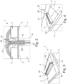
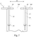
- FIG 7 a further embodiment of an extractor device 2 is shown.
- the upper end of the suction shaft 24 is covered by a cover plate 200 .
- a recess, which forms the air inlet opening 290, and two recesses, each of which forms a passage opening 29, are made in the cover plate 200.
- the through-openings 29 are arranged adjacent to the air inlet opening 290 and the air inlet opening 290 is between the through-openings 29.
- the extractor device 2 has two screen elements 21, 22 which extend through the through-openings 29 and protrude upwards. The lower end of each of the screen elements 21, 22 is held in a fastening element 25 in each case.
- the fastening element 25 represents a rail which is open at the top and into which the lower end of the respective screen element 21, 22 can be inserted.
- the rail can extend over the entire width of the screen element 21, 22.
- the rail only accommodates the lateral area of the lower end of the screen elements.
- the rail or another rail can extend in the vertical direction and accommodate the lower area of the side edge of the respective screen element 21, 22.
- the fastening element 25 can be fastened to a side wall of the suction shaft 24, for example.
- the fastening element or elements 25 are fixedly fastened to the suction shaft 24 .
- a fastening element 25 is preferably provided on opposite side walls of the suction shaft 24 in each case.
- FIG 8 a further embodiment of the kitchen appliance 1 according to the invention is shown.
- the fume extraction device 2 has three screen elements 21, 22, 22'.
- the vapor extraction device 2 has a rear screen element 21 and two front screen elements 22, 22'.
- the front screen elements 22, 22' are arranged laterally adjacent to one another in one plane. There is a distance between the mutually facing side edges of the two screen elements 22, 22'.
- the height of the front screen elements 22, 22' is in each case less than the height of the rear screen element 21.
- the width of the two front screen elements 22, 22', together with the distance between the screen elements 22, 22', is smaller than the width of the rear screen element 21
- the suction gap 20, through which air is sucked in extends both between the respective top edge of each of the front screen elements 22, 22' and the top edge of the rear screen element 21 and along the side edges of the front screen elements 22, 22 ⁇ .
- a further part of the intake gap 20 is formed between the outer side edge of the respective front screen element 22, 22' and the respective outer side edge of the rear screen element 21.
- a further part of the intake gap 20 is also formed between the respective side edges of the front screen elements 22, 22', which face one another, and the central region of the rear screen element 21.
- the flow of air is in the figure 8 indicated schematically by block arrows.
- the front screen elements 22, 22', like the rear screen element 21, are detachably held on the fume extraction device 2.
- the present invention creates an extractor device, which can also be referred to as an extractor hood, which can be arranged behind the hob like known downdrafts, but especially when the screen elements are made of a transparent material and do not represent an optical barrier like conventional downdrafts.
- the intake flow can be optimized if the vapors can also be sucked in laterally (on the sides and/or in the middle) and not just from above.
- a screen element made of glass serves as an easy-to-clean splash guard.
- the vapor trap according to the invention does not move up and down like the conventional downdraft, but remains fixed as a product and protrudes upwards over the table, the worktop or the hob.
- the extractor device has two glass panes that are arranged one behind the other.
- the glass panes are preferably behind the hob.
- the vapor is drawn in horizontally at the top and can also be sucked in along the vertical, in particular laterally and/or centrally.
- the glass or other plate material can also serve as a splash guard and as an optical waveguide.
- Light can be coupled in from below over the edge. Appropriate edge processing helps with the decoupling and direction of the light beam.
- the present invention has a number of advantages. On the one hand, no mechanical device, for example no moving device and no drive, is no longer required, which one would like to hide. In the embodiment in which the extractor device has two front screen elements, air is also sucked in horizontally in the middle. Due to the omission of a motor movement, a slimmer (less deep) downdraft extractor can be produced with the extractor device according to the invention. The depth of the extractor device can be less than 120mm and can be reduced to 90mm, for example, because there are no motors and flaps. Thus, the extractor according to the invention is also easier to install in the work surface. In addition, since the screen elements are detachably fastened and can therefore be removed without tools, the fat label can be improved since the contaminants deposited on the screen elements are calculated together with the contaminants on filters.
Description
Die vorliegende Erfindung betrifft eine Dunstabzugsvorrichtung und ein Küchengerät mit Kochfeld und Dunstabzugsvorrichtung.The present invention relates to an extractor device and a kitchen appliance with a hob and an extractor device.
Zum Reinigen von Dünsten und Wrasen, die beim Kochen auf einem Kochfeld entstehen, ist es bekannt, Dunstabzugshauben zu verwenden, die oberhalb des Kochfeldes beispielsweise an einer Raumwand befestigt sind. Diese Dunstabzugshauben saugen die Dünste und Wrasen nach oben ab. Zudem sind auch sogenannte Muldenlüftungen oder Downdraft-Vorrichtungen bekannt, bei denen Dünste und Wrasen nach unten abgesaugt werden.To clean fumes and vapors that arise when cooking on a hob, it is known to use extractor hoods that are attached above the hob, for example on a room wall. These extractor hoods suck the fumes and vapors upwards. In addition, so-called trough ventilation or downdraft devices are also known, in which vapors and vapors are sucked off downwards.
In der
In der
In der
Eine Muldenlüftung ist beispielsweise in der
Ein Nachteil dieser Vorrichtung besteht darin, dass die Effizienz der Dunstabzugsvorrichtung gering ist, da die Absaugöffnung groß ist und somit neben dem zu erfassenden Wrasen auch reine Luft eingesaugt wird, die Dunstabzugshaube schwer zu reinigen ist und die Muldenlüftung zudem einen komplexen Aufbau aufweist.A disadvantage of this device is that the efficiency of the extractor device is low because the extraction opening is large and therefore clean air is also sucked in in addition to the vapors to be captured, the extractor hood is difficult to clean and the downdraft ventilation also has a complex structure.
Aufgabe der vorliegenden Erfindung ist es daher, eine Dunstabzugsvorrichtung zu schaffen, die bei einfachem Aufbau die Effizienz der Wrasenerfassung steigert und die zudem leicht zu reinigen ist.It is therefore the object of the present invention to provide an extractor device which, with a simple structure, increases the efficiency of vapor capture and which is also easy to clean.
Gemäß einem ersten Aspekt wird die Aufgabe gelöst durch eine Dunstabzugsvorrichtung mit einem Absaugschacht, in dessen oberen Ende eine Lufteintrittsöffnung und mindestens eine Durchlassöffnung gebildet ist, und mindestens einem in dem Absaugschacht gelagerten Wrasenfang mit mindestens einem Absaugspalt. Der Wrasenfang besteht aus mindestens zwei flächigen Schirmelementen, die eben sind und parallel zueinander angeordnet sind, wobei zwischen den Schirmelementen der Absaugspalt gebildet ist, die mindestens zwei Schirmelemente teilweise über die Durchlassöffnung des Absaugschachtes hinaus ragen, die mindestens zwei Schirmelemente lösbar in dem Absaugschacht feststehend gelagert sind und eines der mindestens zwei Schirmelemente eine größere Fläche aufweist als das mindestens eine weitere Schirmelement.According to a first aspect, the object is achieved by a fume extraction device with a suction shaft, in the upper end of which an air inlet opening and at least one passage opening is formed, and at least one vapor trap mounted in the suction shaft with at least one suction gap. The vapor trap consists of at least two flat screen elements that are flat and arranged parallel to one another, with the suction gap being formed between the screen elements, the at least two screen elements partially protrude beyond the passage opening of the suction shaft, the at least two screen elements are detachably and fixedly mounted in the suction shaft and one of the at least two screen elements has a larger area than the at least one other screen element.
Als Dunstabzugsvorrichtung wird eine Vorrichtung bezeichnet, mittels derer Dünste und Wrasen von einem Kochfeld oder einer Arbeitsfläche abgesaugt und vorzugsweise gereinigt werden können. Die Dunstabzugsvorrichtung umfasst dabei einen Absaugschacht und einen Wrasenfang. Zusätzlich umfasst die Dunstabzugsvorrichtung vorzugsweise zumindest ein Gebläse oder ist mit einem Gebläse verbunden, über das Unterdruck erzeugt wird, mittels dessen die Dünste und Wrasen in den Wrasenfang und darüber in den Absaugschacht angesaugt werden können. Zudem umfasst die Dunstabzugsvorrichtung vorzugsweise mindestens ein Filterelement, das beispielsweise in dem Absaugschacht angeordnet sein kann und an dem Verunreinigungen, wie Fett oder Flüssigkeitspartikel aus den Dünsten und Wrasen abgeschieden werden können.An extractor device is a device by means of which vapors and vapors can be extracted from a hob or a work surface and preferably cleaned. The fume extraction device includes a suction shaft and a vapor trap. In addition, the fume extraction device preferably comprises at least one fan or is connected to a fan, via which negative pressure is generated, by means of which the vapors and fumes can be sucked into the vapor catcher and above it into the suction shaft. In addition, the fume extraction device preferably includes at least one filter element, for example in the suction shaft can be arranged and where impurities such as fat or liquid particles can be separated from the vapors and vapors.
Der Absaugschacht weist erfindungsgemäß eine Lufteintrittsöffnung auf. Die Lufteintrittsöffnung ist im oberen Ende des Absaugschachtes gebildet. Zudem ist in dem oberen Ende des Absaugschachtes mindestens eine Durchlassöffnung gebildet, durch die sich das mindestens eine Schirmelement nach oben erstreckt. Da mindestens zwei Schirmelemente vorgesehen sind, sind in dem oberen Ende des Absaugschachtes mindestens zwei Durchlassöffnungen gebildet. Ist der Absaugschacht nach oben offen, so liegen die Durchlassöffnungen und die Lufteintrittsöffnung beide in der durch den oberen Rand des Absaugschachtes gebildeten Öffnung, das heißt bilden gemeinsam diese Öffnung. Die Schirmelemente, aus denen der Wrasenfang besteht, liegen dabei vorzugsweise am Rand der Öffnung, die durch den oberen Rand des Absaugschachtes gebildet ist. Die Randbereiche dieser Öffnung werden daher als Durchlassöffnungen bezeichnet. Die Lufteintrittsöffnung wird daher durch den Abstand zwischen den Schirmelementen in der Öffnung, die durch den oberen Rand des Absaugschachtes gebildet ist, gebildet. Ein Rahmen oder eine andere Trennung liegt bei dieser Ausführungsform zwischen der Lufteintrittsöffnung und den Durchlassöffnungen nicht vor. Gemäß einer Ausführungsform ist es allerdings auch möglich, dass das obere Ende des Absaugschachtes durch eine Deckplatte abgedeckt ist, in der zumindest zwei Schlitze, die die Durchlassöffnungen darstellen, eingebracht sind, durch die jeweils mindestens ein Schirmelement aus dem Absaugschacht nach oben übersteht. Zusätzlich ist bei dieser Ausführungsform eine Öffnung in die Deckplatte eingebracht, die die Lufteintrittsöffnung darstellt. Diese kann zu den Durchlassöffnungen benachbart liegen und die Lufteintrittsöffnung liegt zwischen den Durchlassöffnungen.According to the invention, the suction shaft has an air inlet opening. The air inlet opening is formed in the upper end of the suction shaft. In addition, at least one passage opening is formed in the upper end of the suction shaft, through which the at least one screen element extends upwards. Since at least two screen elements are provided, at least two passage openings are formed in the upper end of the suction shaft. If the suction shaft is open at the top, the passage openings and the air inlet opening are both in the opening formed by the upper edge of the suction shaft, that is to say they form this opening together. The screen elements that make up the vapor trap are preferably located at the edge of the opening that is formed by the upper edge of the suction shaft. The edge areas of this opening are therefore referred to as passage openings. The air inlet opening is therefore formed by the distance between the screen elements in the opening formed by the upper edge of the suction shaft. In this embodiment, there is no frame or other separation between the air inlet opening and the passage openings. According to one embodiment, however, it is also possible for the upper end of the suction shaft to be covered by a cover plate in which at least two slits, which represent the passage openings, are introduced, through which at least one screen element protrudes upwards from the suction shaft. In addition, in this embodiment, an opening is made in the cover plate, which represents the air inlet opening. This can be adjacent to the through-openings and the air inlet opening is between the through-openings.
Richtungsangaben, wie oben und unten beziehen sich - soweit nicht anders angegeben - auf eine Dunstabzugsvorrichtung im montierten Zustand. Insbesondere beziehen sich diese Angaben auf eine Dunstabzugsvorrichtung, bei der das obere Ende des Absaugschachtes und damit auch die Durchlassöffnungen in der Horizontalen liegen.Unless otherwise stated, directions given above and below refer to an installed extractor hood. In particular, this information relates to a fume extraction device in which the upper end of the suction shaft and thus also the passage openings are in the horizontal.
Der Absaugschacht erstreckt sich von der Durchlassöffnung aus vorzugsweise in der Vertikalen nach unten. Der Absaugschacht kann auch als Absaugkanal bezeichnet werden und ist an dem Ende, das dem oberen Ende abgewandt ist, mit dem Gebläse der Dunstabzugsvorrichtung oder dem daran angeschlossenen Gebläse verbunden. In dem Absaugschacht ist ein Wrasenfang gelagert. Der Wrasenfang weist mindestens einen Absaugspalt auf, der auch als Ansaugspalt bezeichnet werden kann. Als Wrasenfang wird erfindungsgemäß der Teil der Dunstabzugsvorrichtung bezeichnet, über den von einem oder mehreren Absaugspalten Luft zu der Lufteintrittsöffnung und damit in den Absaugschacht geleitet wird.The suction shaft preferably extends vertically downwards from the passage opening. The suction shaft can also be referred to as a suction channel and is connected to the fan of the vapor extraction device at the end that faces away from the upper end or the fan connected to it. A vapor trap is mounted in the suction shaft. The vapor trap has at least one suction gap, which can also be referred to as the suction gap. According to the invention, vapor trap means that part of the fume extraction device via which air is conducted from one or more suction gaps to the air inlet opening and thus into the suction shaft.
Erfindungsgemäß besteht der Wrasenfang aus mindestens zwei flächigen Schirmelementen. Als Schirmelemente werden die Teile bezeichnet, die gemeinsam den Ansaugtrakt des Wrasenfangs bilden. Insbesondere werden als Schirmelemente die Teile bezeichnet, die den mindestens einen Absaugspalt sowie eine Luftleitung zu dem Absaugschacht bilden. Die Schirmelemente stellen Platten dar, die eben sind.According to the invention, the vapor trap consists of at least two flat screen elements. The parts that together form the suction tract of the vapor catcher are referred to as screen elements. In particular, the parts that form the at least one suction gap and an air line to the suction shaft are referred to as screen elements. The screen elements represent panels that are planar.
Die Schirmelemente sind so angeordnet, dass der Abstand zwischen den Schirmelementen über deren Höhe gleich ist. Die ebenen Schirmelemente sind daher parallel zueinander ausgerichtet.The screen elements are arranged in such a way that the distance between the screen elements is the same over their height. The flat screen elements are therefore aligned parallel to one another.
Die Schirmelemente bestehen vorzugsweise aus einem durchsichtigen Material. Beispielsweise können die Schirmelemente aus Glas oder Kunststoff bestehen. Die Schirmelemente werden im Folgenden auch als Scheiben bezeichnet.The screen elements are preferably made of a transparent material. For example, the screen elements can be made of glass or plastic. The screen elements are also referred to below as panes.
Zwischen den Schirmelementen ist bei der erfindungsgemäßen Dunstabzugsvorrichtung der Absaugspalt gebildet. Der Absaugspalt kann hierbei durch den Abstand der Flächen der Schirmelemente gebildet sein. Vorzugsweise wird der Absaugspalt durch den Abstand der entsprechenden Kanten zweier Schirmelemente gebildet. Beispielsweise kann ein Teil des Absaugspaltes oder der gesamte Absaugspalt durch den Abstand der Oberkanten zweier benachbarter Schirmelemente gebildet sein. Der Abstand kann in der Horizontalen liegen oder zu dieser geneigt sein. Ein weiterer Teil des Absaugspaltes kann beispielsweise durch den Abstand der Seitenkanten zweier Schirmelemente gebildet sein. Dieser Teil des Absaugspaltes kann in der Vertikalen oder dazu geneigt liegen.In the vapor extraction device according to the invention, the suction gap is formed between the screen elements. The suction gap can be formed here by the distance between the surfaces of the screen elements. The suction gap is preferably formed by the distance between the corresponding edges of two screen elements. For example, part of the suction gap or the entire suction gap can be formed by the distance between the upper edges of two adjacent screen elements. The distance can lie in the horizontal or be inclined to this. Another part of the suction gap can be formed, for example, by the distance between the side edges of two screen elements. This part of the suction gap can be vertical or inclined to it.
Erfindungsgemäß ragen die mindestens zwei Schirmelemente über die Durchlassöffnungen des Absaugschachtes hinaus. Die Schirmelemente ragen hierbei nach oben über die Durchlassöffnungen hinaus.According to the invention, the at least two screen elements protrude beyond the passage openings of the suction shaft. In this case, the screen elements protrude upwards beyond the passage openings.
Zudem sind die mindestens zwei Schirmelemente erfindungsgemäß lösbar in dem Absaugschacht gelagert. Als lösbare Lagerung wird eine Befestigung bezeichnet, die ohne Werkzeuge gelöst werden kann, das heißt bei der das Schirmelement werkzeuglos von der Dunstabzugsvorrichtung abgenommen werden kann. Jedes Schirmelement ist vorzugsweise separat in dem Absaugschacht befestigt. Die Befestigung kann beispielsweise ein Einschieben, ein Einklemmen oder ein Verrasten des Schirmelementes mit einem Befestigungselement sein. Beispielsweise kann das Befestigungselement eine Schiene sein, in die das Schirmelement eingeschoben werden kann. Die Schirmelemente können separat voneinander von dem Befestigungselement und damit von der Dunstabzugsvorrichtung gelöst werden. Die Lagerung der Schirmelemente ist erfindungsgemäß feststehend. Insbesondere ist daher das mindestens eine Befestigungselement fest an der Dunstabzugsvorrichtung und insbesondere fest an dem Absaugschacht befestigt.In addition, the at least two screen elements are, according to the invention, detachably mounted in the suction shaft. A detachable mounting is a fastening that can be released without tools, ie in which the screen element can be removed from the vapor extraction device without tools. Each screen element is preferably attached separately in the suction duct. The fastening can be, for example, pushing in, clamping in or latching the screen element to a fastening element. For example, the fastening element can be a rail into which the screen element can be inserted. The screen elements can be detached from the fastening element and thus from the extractor device separately from one another. According to the invention, the mounting of the screen elements is fixed. In particular, therefore, the at least one fastening element is firmly attached to the extractor device and in particular firmly to the suction shaft.
Indem erfindungsgemäß mindestens zwei flächige Schirmelemente verwendet werden, zwischen den Schirmelementen der Absaugspalt gebildet ist, die Schirmelemente über die Durchlassöffnungen des Absaugschachtes nach oben herausragen und die mindestens zwei Schirmelemente lösbar in dem Absaugschacht feststehend gelagert sind, kann eine Reihe von Vorteilen erzielt werden. Durch die Bereiche der Schirmelemente, die über die Durchlassöffnungen des Absaugschachtes hinausragen, wird die Luftführung der Luft von dem Ansaugspalt zu dem Absaugschacht, insbesondere zu der Lufteintrittsöffnung, gebildet. Indem zudem die Schirmelemente lösbar in dem Absaugschacht gelagert sind, können diese auf einfache Weise von der Dunstabzugsvorrichtung entnommen werden. Im entnommenen Zustand können die Schirmelemente, beispielsweise in einer Spülmaschine gereinigt werden. Beim Absaugen von Dünsten und Wrasen werden sich an den Schirmelementen Verunreinigungen ablagern. Indem die Schirmelemente werkzeuglos von der Dunstabzugsvorrichtung abgenommen werden und gereinigt werden können, können diese als Filter fungieren, das heißt zur Abscheidung der Verunreinigungen verwendet werden. Besonders bevorzugt werden die Schirmelemente zumindest teilweise durch ihr Eigengewicht in dem Absaugschacht und insbesondere an dem Befestigungselement gehalten. Insbesondere bei Schirmelementen, die aus Glas bestehen, kann durch das hohe Eigengewicht ein sicherer Halt, beispielsweise in einer Schiene gewährleistet werden. Indem die Scheibenelemente feststehend in der Dunstabzugsvorrichtung gehalten sind, ist der Aufbau der Dunstabzugsvorrichtung vereinfacht. Insbesondere sind keine Bewegungsvorrichtungen, wie Antriebe und Motoren notwendig. Zudem verringern sich auch die Größe der Dunstabzugsvorrichtung und damit der dafür erforderliche Bauraum.A number of advantages can be achieved by using at least two flat screen elements according to the invention, the suction gap being formed between the screen elements, the screen elements protruding upwards over the passage openings of the suction shaft and the at least two screen elements being detachably and fixedly mounted in the suction shaft. The areas of the screen elements that protrude beyond the passage openings of the suction chute form the air guidance of the air from the suction gap to the suction chute, in particular to the air inlet opening. Since the screen elements are also mounted detachably in the suction shaft, they can be easily removed from the fume extraction device. When removed, the screen elements can be cleaned in a dishwasher, for example. When extracting fumes and vapors, impurities will be deposited on the screen elements. Since the screen elements can be removed from the vapor extraction device without tools and cleaned, they can act as filters, i.e. be used to separate contaminants. The screen elements are particularly preferably held at least partially in the suction shaft and in particular on the fastening element by their own weight. In particular in the case of screen elements made of glass, the high inherent weight can ensure a secure hold, for example in a rail. The construction of the vapor extraction device is simplified by the disc elements being held fixed in the vapor extraction device. In particular, no movement devices such as drives and motors are necessary. Also reduce the size of the vapor extraction device and thus the space required for it.
Erfindungsgemäß weist eines der mindestens zwei Schirmelemente eine größere Fläche auf als das mindestens eine weitere Schirmelement. Insbesondere ist das hintere Schirmelement, das heißt das einem Kochfeld abgewandte Schirmelement größer als das oder die vorderen Schirmelement(e). Insbesondere weist das größere Schirmelement eine größere Breite und größere Höhe als das mindestens eine weitere Schirmelement auf. Die Unterkanten der mindestens zwei Schirmelemente liegt vorzugsweise auf einer gemeinsamen Höhe. Die Oberkante des oder der vorderen Schirmelemente(s) liegt bei dieser Ausführungsform tiefer als die Oberkante des hinteren Schirmelementes. Sind nur zwei Schirmelemente vorgesehen, so sind die Schirmelemente so zueinander angeordnet, dass deren Breitenmitten auf einer Linie liegen. Sind zwei vordere Schirmelemente vorgesehen, so ist deren Breite vorzugsweise so gewählt, dass die Summe der Breiten und des zwischen den vorderen Schirmelementen vorliegenden Abstandes geringer ist als die Breite des hinteren Schirmelementes.According to the invention, one of the at least two screen elements has a larger area than the at least one other screen element. In particular, the rear screen element, ie the screen element facing away from a hob, is larger than the front screen element(s). In particular, the larger screen element has a greater width and greater height than the at least one further screen element. The lower edges of the at least two screen elements are preferably at a common height. In this embodiment, the top edge of the front screen element(s) is lower than the top edge of the rear screen element. If only two screen elements are provided, the screen elements are arranged in relation to one another in such a way that their width centers lie on a line. If two front screen elements are provided, their width is preferably chosen such that the sum of the widths and the distance between the front screen elements is less than the width of the rear screen element.
Indem ein Schirmelement, vorzugsweise das hintere Schirmelement eine größere Fläche aufweist, wird der Absaugspalt in dessen Höhenrichtung vergrößert. Insbesondere liegt der Absaugspalt bei dieser Ausführungsform aus der Horizontalen geneigt und erstreckt sich von den Kanten des oder der kleineren Schirmelemente zu den Kanten des größeren Schirmelementes. Zudem wird durch diese Ausführungsform auch ein seitlicher Einzug von Luft, das heißt über die Abstände zwischen den äußeren Seitenkanten des oder der vorderen Schirmelemente und den Seitenkanten des hinteren Schirmelementes, ermöglicht.Because a screen element, preferably the rear screen element, has a larger area, the suction gap is increased in its height direction. In particular, the suction gap in this embodiment is inclined from the horizontal and extends from the edges of the smaller screen element or elements to the edges of the larger screen element. In addition, this embodiment also allows air to be drawn in laterally, ie via the distances between the outer side edges of the front screen element or elements and the side edges of the rear screen element.
Gemäß einer Ausführungsform liegen die oberen Kanten der mindestens zwei Schirmelemente in unterschiedlichen Höhen oberhalb der Durchlassöffnungen des Absaugschachtes. Das Schirmelement, dessen obere Kante in einer geringeren Höhe liegt, ist dabei vorzugsweise dem Kochfeld zugewandt und das Schirmelement, dessen Oberkante in einer größeren Höhe liegt, liegt hinter diesem Schirmelement. Hierdurch wird das zuverlässige Einsaugen von Wrasen gewährleistet. Zum einen ist die Größe des Absaugspaltes, der zwischen den Oberkanten der Schirmelemente gebildet ist, größer als bei Schirmelementen, deren oberen Kanten in dergleichen Höhe liegen. Der Absaugspalt liegt hierbei nämlich aus der Horizontalen geneigt und weist bei gleichem Abstand der Schirmelemente zueinander eine größere Größe auf. Zudem wird das Ansaugen bei dieser Ausführungsform auch dadurch unterstützt, dass ein Vorbeistreifen von Wrasen an dem hinteren Schirmelement durch dessen größere Höhe oberhalb der Lufteintrittsöffnung verhindert werden kann. Zudem kann das vordere Schirmelement, das dem Kochfeld zugewandt ist, bei der erfindungsgemäßen Dunstabzugsvorrichtung in einer solchen Position liegen, dass dessen Oberkante auf einer Höhe liegt, die der Höhe eines auf dem Kochfeld befindlichen Gargefäßes entspricht. Somit liegt der Absaugspalt der Dunstabzugsvorrichtung in die Nähe der Oberkante des Gargefäßes und es kann damit ein zuverlässiges Absaugen gewährleistet werden. Durch das hochstehende hintere Schirmelement kann weiterhin ein Spritzschutz für eine Raumwand, die hinter der Dunstabzugsvorrichtung liegen kann, geschaffen werden.According to one embodiment, the upper edges of the at least two screen elements are at different heights above the passage openings of the suction shaft. The screen element, the upper edge of which is at a lower level, preferably faces the hob and the screen element, the upper edge of which is at a higher level, is located behind this screen element. This ensures that vapors are sucked in reliably. On the one hand, the size of the suction gap formed between the upper edges of the screen elements is larger than in the case of screen elements whose upper edges are at the same height. The suction gap is in this case inclined from the horizontal and has a larger size with the same distance between the screen elements. In addition, the suction is also supported in this embodiment in that vapors can be prevented from brushing past the rear screen element due to its greater height above the air inlet opening. In addition, the front screen element, which faces the hob, can be in such a position in the extractor device according to the invention that its upper edge is at a height that corresponds to the height of a cooking vessel on the hob. The suction gap of the fume extractor device is therefore close to the top edge of the cooking vessel and reliable suction can thus be guaranteed. The raised rear screen element can also be used to create a splash guard for a room wall that can be located behind the extractor hood.
Es liegt aber auch im Rahmen der Erfindung, dass die Oberkanten der mindestens zwei Schirmelemente in der gleichen Höhe liegen. Bei dieser Ausführungsform können die mindestens zwei Schirmelemente mit deren Oberkante auf der gleichen Höhe oberhalb der Durchlassöffnungen liegen. Diese Ausführungsform ist besonders bevorzugt, wenn die Dunstabzugsvorrichtung zwischen benachbarten Kochfeldern angeordnet ist, da dabei von beiden Kochfeldern zuverlässig Dünste und Wrasen eingesaugt werden können. Auch bei einer in ein Kochfeld mittig integrierten Dunstabzugsvorrichtung ist diese Ausführungsform vorteilhaft, da dabei von den zu der Dunstabzugsvorrichtung benachbarten Kochzonen des Kochfeldes Dünste und Wrasen zuverlässig eingesaugt werden können.However, it is also within the scope of the invention for the upper edges of the at least two screen elements to be at the same height. In this embodiment, the upper edge of the at least two screen elements can be at the same height above the passage openings. This embodiment is particularly preferred when the fume extraction device is arranged between adjacent hobs, since fumes and vapors can be reliably sucked in from both hobs. This embodiment is also advantageous in the case of an extractor device integrated centrally in a cooktop, since vapors and vapors can be reliably sucked in from the cooking zones of the cooktop adjacent to the extractor device.
Der Absaugspalt verläuft vorzugsweise zumindest entlang der oberen Kante zumindest eines der Schirmelemente und entlang der Seitenkanten des zumindest einen Schirmelementes. Bei der Ausführungsform, bei der zwei vordere Schirmelemente vorgesehen sind, erstreckt sich der Absaugspalt auch entlang des Abstandes der beiden vorderen Schirmelemente. Hierdurch kann zum einen ein zuverlässiges Absaugen aufgrund der großen Länge des Absaugspaltes gewährleistet werden. Zudem kann durch das seitliche und/oder mittige Ansaugen eine Strömung erzeugt werden, durch die der Wrasen abgelenkt wird und so das Absaugen weiter verbessert wird.The suction gap preferably runs at least along the upper edge of at least one of the screen elements and along the side edges of the at least one screen element. In the embodiment in which two front screen elements are provided, the suction gap also extends along the distance between the two front screen elements. In this way, on the one hand, reliable suction can be ensured due to the great length of the suction gap. In addition, a flow can be generated by the lateral and/or central suction, by which the vapor is deflected and the suction is thus further improved.
Die Dunstabzugsvorrichtung kann zwei Schirmelemente aufweisen, die den Wrasenfang bilden. Die Erfindung wird daher im Folgenden vorwiegend anhand einer Dunstabzugsvorrichtung mit zwei Schirmelementen beschrieben.The extractor device can have two screen elements that form the vapor trap. The invention is therefore described in the following primarily on the basis of an extractor device with two screen elements.
Gemäß einer Ausführungsform weist die Dunstabzugsvorrichtung aber drei Schirmelemente auf. Bei dieser Ausführungsform sind die Schirmelemente so angeordnet, dass zwei seitlich zueinander benachbart und zu dem dritten Schirmelement horizontal versetzt liegen. Ist am oberen Ende des Absaugschachtes eine Deckplatte vorgesehen, so sind in dieser vorzugsweise eine Durchlassöffnung für ein hinteres Schirmelement und für jedes vordere Schirmelement jeweils eine separate Durchlassöffnung oder eine gemeinsame Durchlassöffnung vorgesehen.According to one embodiment, however, the fume extraction device has three screen elements. In this embodiment, the screen elements are arranged in such a way that two are laterally adjacent to one another and offset horizontally with respect to the third screen element. If a cover plate is provided at the upper end of the suction shaft, a through-opening for a rear screen element and a separate through-opening or a common through-opening are preferably provided in this cover plate for each front screen element.
Richtungsangaben, wie vorne oder hinten beziehen sich - soweit nicht anders angegeben - auf eine Dunstabzugsvorrichtung, die in oder an einem Kochfeld montiert ist. Als Vorne wird dabei die Richtung bezeichnet, die dem Kochfeld oder einer Kochzone zugewandt ist und als Hinten die Richtung, die dem Kochfeld oder einer Kochzone abgewandt ist.Unless otherwise stated, directions such as front or rear refer to an extractor hood that is installed in or on a hob. The front is the direction that faces the hob or a cooking zone, and the rear is the direction that faces away from the hob or a cooking zone.
Bei der Ausführungsform der Dunstabzugsvorrichtung mit drei Schirmelementen sind die zwei seitlich zueinander benachbarten Schirmelemente vorzugsweise die vorderen Schirmelemente und das dritte Schirmelement stellt das hintere Schirmelement dar. Insbesondere liegen die zwei seitlich zueinander benachbarten Schirmelemente vor der Lufteinlassöffnung der Dunstabzugsvorrichtung und das hintere Schirmelement hinter der Lufteinlassöffnung. Als seitlich benachbart werden Schirmelemente bezeichnet, bei denen eine Seitenkante eines Schirmelementes einer Seitenkante eines weiteren Schirmelementes zugewandt ist und die beiden Schirmelemente in einer gemeinsamen Ebene liegen. Das dritte Schirmelement liegt bei dieser Ausführungsform vorzugsweise in einer Ebene, die zu der Ebene der ersten zwei Schirmelemente nach hinten versetzt ist. Besonders bevorzugt ist zwischen den zueinander seitlich benachbarten Schirmelementen ein Abstand gegeben. Durch diesen Abstand wird ein weiterer Teil des Ansaugspaltes gebildet. Insbesondere kann über diesen Teil des Ansaugspaltes Luft, die die Dunstabzugsvorrichtung von vorne anströmt, in der Waagerechten eingesaugt werden und damit die zu dem Ansaugspalt gerichtete Strömung verstärkt werden. Bei dieser Ausführungsform wird der Ansaugspalt somit zumindest durch den Abstand der oberen Kanten der vorderen Schirmelemente zu der oberen Kante des hinteren Schirmelementes sowie durch den Abstand zwischen den vorderen Schirmelementen gebildet. Zudem kann auch zwischen den Seitenkanten der vorderen Schirmelemente, die dem jeweils anderen vorderen Schirmelement abgewandt sind, und den Seitenkanten des hinteren Schirmelementes ein weiterer Teil des Ansaugspaltes gebildet sein.In the embodiment of the vapor extraction device with three screen elements, the two laterally adjacent screen elements are preferably the front screen elements and the third screen element represents the rear screen element. In particular, the two laterally adjacent screen elements are in front of the air inlet opening of the vapor extraction device and the rear screen element is behind the air inlet opening. Laterally adjacent screen elements are those in which a side edge of one screen element faces a side edge of a further screen element and the two screen elements lie in a common plane. In this embodiment, the third screen element preferably lies in a plane which is offset to the rear from the plane of the first two screen elements. In a particularly preferred manner, there is a spacing between the screen elements that are laterally adjacent to one another. This distance forms another part of the intake gap. In particular, via this part of the intake gap, air flowing against the vapor extraction device from the front can be sucked in horizontally and the flow directed to the intake gap can thus be intensified. In this embodiment, the suction gap is thus at least determined by the distance between the upper edges of the front screen elements and the upper edge of the rear screen element and by the distance formed between the front screen elements. In addition, another part of the intake gap can also be formed between the side edges of the front screen elements, which face away from the other front screen element in each case, and the side edges of the rear screen element.
Bei der Ausführungsform, bei der die Dunstabzugsvorrichtung drei Schirmelemente aufweist, von denen zwei seitlich zueinander benachbart und zu dem dritten Schirmelement horizontal versetzt angeordnet sind, weist vorzugsweise das horizontal versetzt angeordnete dritte Schirmelement eine größere Fläche als die zwei seitlich zueinander versetzten Schirmelemente auf. Das horizontal versetzte Schirmelement ist dabei vorzugsweise das hintere Schirmelement und die beiden benachbarten Schirmelemente sind die vorderen Schirmelemente.In the embodiment in which the vapor extraction device has three screen elements, two of which are arranged laterally adjacent to one another and horizontally offset from the third screen element, the horizontally offset third screen element preferably has a larger area than the two laterally offset screen elements. The horizontally offset screen element is preferably the rear screen element and the two adjacent screen elements are the front screen elements.
Vorzugsweise ist jedes der Schirmelemente in einem Befestigungselement aufgenommen, die vorzugsweise eine Schiene darstellt. Das Befestigungselement ist dabei feststehend in dem Absaugschacht montiert. Indem das Schirmelement an einem Befestigungselement, das feststehend gelagert ist, lösbar befestigt ist, wird beim Abnehmen des Schirmelementes nur das Schirmelement selber von der Dunstabzugsvorrichtung getrennt. Das Befestigungselement hingegen kann in der Dunstabzugsvorrichtung verbleiben. Stellt das Befestigungselement eine Schiene dar, so kann das flächige Schirmelement, das vorzugsweise eine Scheibe darstellt, auf einfache Weise von oben in die Schiene eingeschoben und zum Entnehmen aus der Schiene herausgezogen werden. Stellt die Schiene eine horizontal verlaufende Schiene dar, kann das Schirmelement zumindest an der gesamten Unterkante und vorzugsweise dem unteren Bereich der Seitenflächen von der Schiene gehalten werden. Stellt die Schiene eine vertikal verlaufende Schiene dar, so ist diese an deren unteren Ende vorzugsweise geschlossen. An dieser Schiene werden daher der seitliche Bereich der Unterkante des Schirmelementes und der untere Bereich der Seitenkante des Schirmelementes gehalten.Preferably, each of the screen elements is received in a fastening element, which is preferably a rail. The fastening element is fixed in the suction shaft. Because the screen element is releasably attached to a fixing element that is fixedly mounted, only the screen element itself is separated from the vapor extraction device when the screen element is removed. The fastening element, on the other hand, can remain in the vapor extraction device. If the fastening element is a rail, then the flat screen element, which is preferably a disc, can be easily pushed into the rail from above and pulled out of the rail for removal. If the rail represents a horizontally running rail, the screen element can be held by the rail at least along the entire lower edge and preferably the lower area of the side surfaces. If the rail is a vertical rail, it is preferably closed at its lower end. The lateral area of the lower edge of the screen element and the lower area of the side edge of the screen element are therefore held on this rail.
Gemäß einer bevorzugten Ausführungsform bestehen die Schirmelemente aus Glas. Diese Ausführungsform ist vorteilhaft, da die Schirmelemente dabei ein hohes Eigengewicht aufweisen. Das Schirmelement kann dadurch zuverlässig in einem Befestigungselement, insbesondere einer Schiene, durch das Eigengewicht gehalten werden. Hierdurch wird der Aufbau der Dunstabzugsvorrichtung weiter vereinfacht, da das Befestigungselement besonders einfach ausgestaltet sein kann und keine weiteren Elemente, wie Klemm- oder Rastelemente aufweisen muss. Zudem lässt sich ein aus Glas bestehendes Schirmelement auf einfache Weise reinigen.According to a preferred embodiment, the screen elements are made of glass. This embodiment is advantageous because the screen elements have a high intrinsic weight. As a result, the screen element can be reliably held in a fastening element, in particular a rail, by its own weight. This further simplifies the structure of the fume extraction device, since the fastening element can be designed in a particularly simple manner and does not have to have any further elements, such as clamping or locking elements. In addition, a screen element made of glass can be cleaned in a simple manner.
Gemäß einer Ausführungsform weist der Absaugschacht der Dunstabzugsvorrichtung eine Tiefe von weniger als 120mm, vorzugsweise 90mm auf. Als Tiefe wird hierbei die Abmessung des Absaugschachtes verstanden, die in der Richtung zwischen den Rändern, an denen die Schirmelemente angeordnet sind, liegt. Somit wird als Tiefe des Absaugschachtes die Abmessung in der Richtung senkrecht zu den Flächen der Schirmelemente verstanden. Eine solche geringe Tiefe kann bei der erfindungsgemäßen Dunstabzugsvorrichtung erreicht werden, da die Dunstabzugsvorrichtung einen besonders einfachen Aufbau aufweist. Insbesondere sind Antriebe oder Motoren sowie Führungselemente, die für eine Bewegung der Schirmelemente notwendig wäre, erfindungsgemäß nicht erforderlich. Durch die geringe Tiefe kann die Dunstabzugsvorrichtung beispielsweise auch hinter einem Kochfeld eingebaut werden, das in der Arbeitsfläche einer Wandzeile integriert ist.According to one embodiment, the suction shaft of the fume extraction device has a depth of less than 120 mm, preferably 90 mm. In this context, the depth is understood to be the dimension of the suction shaft that lies in the direction between the edges on which the screen elements are arranged. Thus, the dimension in the direction perpendicular to the surfaces of the screen elements is understood as the depth of the suction shaft. Such a small depth can be achieved with the vapor extraction device according to the invention, since the vapor extraction device has a particularly simple structure. In particular, drives or motors and guide elements that would be necessary for moving the screen elements are not required according to the invention. Due to the small depth, the extractor device can also be installed, for example, behind a hob that is integrated in the work surface of a row of walls.
Gemäß einer Ausführungsform umfasst die Dunstabzugsvorrichtung mindestens eine Beleuchtungsvorrichtung. Die Beleuchtungsvorrichtung kann beispielsweise an der Oberkante oder Unterkante zumindest eines der Schirmelemente vorgesehen sein und beispielsweise aus Leuchtdioden bestehen. Bei einem transparenten Material der Schirmelemente kann durch eine an der Unterkante angeordneten Beleuchtungsvorrichtung das Licht in das Schirmelement eingekoppelt werden und das gesamte Schirmelement das Licht abgeben und somit eine flächige Beleuchtung bilden. Diese Ausführungsform kann bei der erfindungsgemäßen Dunstabzugsvorrichtung besonders vorteilhaft genutzt werden, da die Schirmelemente über die Durchlassöffnungen nach oben ragen und somit als Beleuchtungs- oder Design-Element fungieren können.According to one embodiment, the fume extraction device comprises at least one lighting device. The lighting device can be provided, for example, on the upper edge or lower edge of at least one of the screen elements and can consist, for example, of light-emitting diodes. If the material of the screen elements is transparent, the light can be coupled into the screen element by an illumination device arranged on the lower edge and the entire screen element can emit the light and thus form a planar illumination. This embodiment can be used particularly advantageously in the fume extraction device according to the invention, since the screen elements project upwards over the passage openings and can therefore function as lighting or design elements.
Bei geeigneter Bearbeitung der Kanten und insbesondere der Oberkante eines oder der Schirmelemente, das aus transparentem Material besteht, kann das Licht aber auch nur über die Kanten abgegeben werden und somit als Funktionslicht dienen. Das oder die Schirmelemente dienen auch hierbei als Lichtleiter.With suitable processing of the edges and in particular the top edge of one or the screen elements, which consists of transparent material, the light can also be emitted only via the edges and thus serve as a functional light. The screen element or elements also serve as a light guide.
Gemäß einem weiteren Aspekt betrifft die Erfindung ein Küchengerät mit mindestens einem Kochfeld und einer erfindungsgemäßen Dunstabzugsvorrichtung. Die Dunstabzugsvorrichtung kann mit dem Kochfeld verbunden sein. Insbesondere kann die Steuerung der Dunstabzugsvorrichtung mit der Steuerung des Kochfeldes verbunden sein. Die Dunstabzugsvorrichtung ist vorzugsweise hinter der Rückseite des Kochfeldes angeordnet und erstreckt sich in Breitenrichtung des Kochfeldes. Vorzugsweise erstreckt sich die Dunstabzugsvorrichtung über die gesamte Breite des Kochfeldes. Als Rückseite des Kochfeldes wird die Seite bezeichnet, die der Seite des Kochfeldes, die dem Benutzer zugewandt ist und an der vorzugsweise Bedienelemente des Kochfeldes vorgesehen sind, abgewandt ist. Die Dunstabzugsvorrichtung kann in einem geringen Abstand zu der Rückseite des Kochfeldes liegen oder an die Rückseite angrenzen. Vorzugsweise ist das Kochfeld in eine Arbeitsplatte eines Küchenschrankes, insbesondere Küchenunterschrankes eingesetzt. Für die Dunstabzugsvorrichtung ist dabei in der Arbeitsplatte eine Aussparung hinter dem Kochfeld eingebracht. In der Aussparung liegt vorzugsweise die Öffnung des Absaugschachtes der Dunstabzugsvorrichtung, in der die Durchlassöffnung(en) vorgesehen sind.According to a further aspect, the invention relates to a kitchen appliance with at least one hob and an extractor device according to the invention. The extractor device can be connected to the hob. In particular, the control of the extractor device can be connected to the control of the hob. The extractor device is preferably arranged behind the back of the hob and extends in the width direction of the hob. The extractor device preferably extends over the entire width of the hob. The back of the hob is the side that faces away from the side of the hob that faces the user and on which the hob controls are preferably provided. The extractor device can be at a small distance from the back of the cooktop or can be adjacent to the back. The hob is preferably used in a worktop of a kitchen cabinet, in particular a kitchen base cabinet. There is a recess in the worktop behind the hob for the extractor device. The opening of the suction shaft of the fume extractor device, in which the passage opening(s) are provided, is preferably located in the recess.
Gemäß einer weiteren Ausführungsform ist die Dunstabzugsvorrichtung in das Kochfeld integriert. Bei dieser Ausführungsform liegt das obere Ende des Absaugschachtes in der Fläche des Kochfeldes. Insbesondere liegen die Durchlassöffnungen und die Lufteintrittsöffnung des Absaugschachtes vorzugsweise in der Mitte der Breite der Fläche des Kochfeldes und erstreckt sich in Tiefenrichtung des Kochfeldes. In dem Kochfeld kann dazu eine entsprechende Aussparung eingebracht sein. In dieser Aussparung liegt das obere Ende des Absaugschachtes, in dem die Durchlassöffnungen ausgebildet sind, über die die mindestens zwei Schirmelemente nach oben herausragen. Die Schirmelemente liegen bei dieser Ausführungsform vorzugsweise so, dass die Oberkanten der mindestens zwei Schirmelemente in der gleichen Höhe liegen. Es liegt aber auch im Rahmen der Erfindung, dass die Schirmelemente unterschiedlich hoch über die Durchlassöffnungen nach oben ragen. Indem die Dunstabzugsvorrichtung in dem Kochfeld integriert ist und insbesondere in der Mitte der Breite des Kochfeldes vorgesehen ist, kann durch die Dunstabzugsvorrichtung Wrasen von Gargefäßen von allen Kochzonen des Kochfeldes zuverlässig abgesaugt werden. Die Dunstabzugsvorrichtung und insbesondere die Schirmelemente liegen nämlich bei dieser Ausführungsform in der unmittelbaren Nähe von beispielsweise vier Kochzonen.According to a further embodiment, the extractor device is integrated into the hob. In this embodiment, the upper end of the suction shaft lies in the surface of the hob. In particular, the passage openings and the air inlet opening of the suction shaft are preferably in the middle of the width of the surface of the hob and extend in the depth direction of the hob. A corresponding recess can be made in the hob for this purpose. The upper end of the suction shaft, in which the passage openings are formed, through which the at least two screen elements protrude, lies in this recess. In this embodiment, the screen elements are preferably positioned in such a way that the upper edges of the at least two screen elements are at the same height. However, it is also within the scope of the invention for the screen elements to project upwards at different heights over the passage openings. Because the extractor device is integrated in the hob and is provided in particular in the middle of the width of the hob, vapors from cooking vessels can be reliably extracted from all cooking zones of the hob by the extractor device. In this embodiment, the extractor device and in particular the screen elements are in the immediate vicinity of, for example, four cooking zones.
Vorteile und Merkmale, die bezüglich der erfindungsgemäßen Dunstabzugsvorrichtung beschrieben werden und wurden, gelten - soweit anwendbar - auch für das erfindungsgemäße Küchengerät und jeweils umgekehrt und werden daher gegebenenfalls nur einmalig beschrieben.Advantages and features that are and have been described with regard to the extractor device according to the invention also apply—insofar as applicable—to the kitchen appliance according to the invention and vice versa and are therefore only described once if necessary.
Die vorliegende Erfindung wird im Folgenden erneut unter Bezugnahme auf die beiliegenden Figuren beschrieben. Es zeigt:
- Figur 1:
- eine schematische Schnittansicht einer Ausführungsform des erfindungsgemäßen Küchengerätes;
- Figur 2:
- eine schematische Schnittansicht einer weiteren Ausführungsform eines Küchengerätes;
- Figur 3:
- eine schematische Perspektivansicht einer weiteren Ausführungsform einesKüchengerätes;
- Figur 4:
- eine schematische Perspektivansicht des Küchengerätes nach
Figur 2 ; - Figur 5:
- eine schematische Perspektivansicht einer weiteren Ausführungsform des erfindungsgemäßen Küchengerätes;
- Figur 6:
- eine schematische Perspektivansicht einer weiteren Ausführungsform des erfindungsgemäßen Küchengerätes;
- Figur 7:
- eine schematische Schnittansicht einer weiteren Ausführungsform eines Küchengerätes mit der Dunstabzugsvorrichtung in einer Betriebsstellung; und
- Figur 8:
- eine schematische Perspektivansicht einer weiteren Ausführungsform des erfindungsgemäßen Küchengerätes mit der Dunstabzugsvorrichtung in einer Betriebsstellung.
- Figure 1:
- a schematic sectional view of an embodiment of the kitchen appliance according to the invention;
- Figure 2:
- a schematic sectional view of a further embodiment of a kitchen appliance;
- Figure 3:
- a schematic perspective view of another embodiment of a kitchen appliance;
- Figure 4:
- a schematic perspective view of the kitchen appliance
figure 2 ; - Figure 5:
- a schematic perspective view of a further embodiment of the kitchen appliance according to the invention;
- Figure 6:
- a schematic perspective view of a further embodiment of the kitchen appliance according to the invention;
- Figure 7:
- a schematic sectional view of a further embodiment of a kitchen appliance with the extractor device in an operating position; and
- Figure 8:
- a schematic perspective view of a further embodiment of the kitchen appliance according to the invention with the extractor device in an operating position.
In
Wie sich aus
Wie sich aus
Die Schirmelemente 21, 22 erstrecken sich von der Durchlassöffnung 29 sowohl nach oben als auch nach unten. Somit liegt der untere Bereich der Schirmelemente 21, 22 in dem Absaugschacht 24. Der untere Rand des Schirmelementes 21 und der untere Rand des Schirmelementes 22 ist jeweils mit einem nicht genauer gezeigten Befestigungselement 25 verbunden. Die Befestigungselemente sind feststehend in dem Absaugschach befestigt. Das Befestigungselement 25 kann den unteren Rand des jeweiligen Schirmelementes 21, 22 zumindest an der Seite und vorzugsweise auch den Bereich der Seitenkante des jeweiligen Schirmelementes 21, 22 einfassen. Das Befestigungselement 25 kann beispielsweise eine nach unten geschlossene vertikal liegende Schiene sein. Bei dieser Ausführungsform wird ein Schirmelement 21 oder 22 vorzugsweise an beiden Seitenkanten jeweils von einem Befestigungselement 25 gehalten. Alternativ oder zusätzlich kann das Befestigungselement 25 auch eine horizontal liegende Schiene sein, die nach oben offen ist. Durch die Befestigungselemente 25 werden die Schirmelemente 21, 22 gehalten. Die Schirmelemente 21, 22 sind von dem jeweiligen Befestigungselement 25 lösbar. Insbesondere können die Schirmelemente 21, 22 einzeln von dem jeweiligen Befestigungselement 25 nach oben herausgezogen werden, ohne dass Werkzeug benötigt wird.The
Die unteren Ränder der Schirmelemente 21, 22 liegen auf einer Ebene. Das hintere Schirmelement 21 weist eine größere Höhe als das vordere Schirmelement 22 auf. Die obere Kante des hinteren Schirmelementes des 21 liegt daher höher als die obere Kante des vorderen Schirmelementes 22. Zwischen den beiden oberen Kanten der Schirmelemente 21,22 wird der Absaugspalt 20 gebildet. Dieser liegt nicht in der Horizontalen, sondern zu dieser geneigt. Das vordere Schirmelement 22 ragt soweit über die Durchlassöffnung 29 nach oben hinaus, dass die obere Kante des vorderen Schirmelementes 22 auf der Höhe des oberen Endes des Gargefäßes, insbesondere des Topfes T, liegt. Somit kann über den Absaugspalt 20 der entstehende Wrasen zuverlässig eingesaugt und in dem Absaugschachtes 24 geleitet werden.The lower edges of the
In
In
In
In
In der
In
Die Erfindung ist nicht auf die gezeigten Ausführungsformen beschränkt. Es liegt beispielsweise auch im Rahmen der Erfindung, dass einzelne Merkmale einer Ausführungsform mit denen einer anderen Ausführungsform kombiniert werden. Beispielsweise können die in
Mit der vorliegenden Erfindung wird eine Dunstabzugsvorrichtung, die auch als Dunstabzug bezeichnet werden kann, geschaffen, die zwar wie bekannte Downdrafts hinter dem Kochfeld angeordnet werden kann, aber insbesondere, wenn die Schirmelemente aus einem transparenten Material bestehen keine optische Barriere darstellt, wie herkömmliche Downdrafts. Zudem kann die Ansaugströmung optimiert werden, wenn auch seitlich (auf den Seiten oder / und in der Mitte) der Wrasen eingesogen werden kann, und nicht nur von oben. Zudem bieten Glasscheiben, die als Schirmelemente vorzugsweise verwendet werden, die Möglichkeit ein Arbeitslicht zu erzeugen. Außerdem dient ein aus Glas bestehendes Schirmelement als gut zu reinigender Spritzschutz.The present invention creates an extractor device, which can also be referred to as an extractor hood, which can be arranged behind the hob like known downdrafts, but especially when the screen elements are made of a transparent material and do not represent an optical barrier like conventional downdrafts. In addition, the intake flow can be optimized if the vapors can also be sucked in laterally (on the sides and/or in the middle) and not just from above. In addition, offer glass panes, which are preferably used as screen elements be able to create a working light. In addition, a screen element made of glass serves as an easy-to-clean splash guard.
Der erfindungsgemäße Wrasenfang fährt nicht hoch und runter, wie der herkömmliche Downdraft, sondern bleibt fix als Produkt stehen und ragt über den Tisch, die Arbeitsplatte oder das Kochfeld nach oben heraus.The vapor trap according to the invention does not move up and down like the conventional downdraft, but remains fixed as a product and protrudes upwards over the table, the worktop or the hob.
Im Gegensatz zu bekannten Dunstabzügen muss bei der erfindungsgemäßen Dunstabzugsvorrichtung und bei dem erfindungsgemäßen Küchengerät kein Kompromiss zwischen guter Performance und einem minimal schönen Design gemacht werden. Allgemein kann ein bekannter Downdraft durch eine Positionserhöhung, leichter hohe Töpfe absaugen und zur Kochflächenbeleuchtung genutzt werden. Damit geht aber eine optische Blockade einher. Bei der vorliegenden Erfindung besteht der Absaugtrakt oberhalb des Absaugschachtes lediglich aus den Schirmelementen, die beispielsweise aus Glas bestehen können. Somit können bei der Erfindung die Vorteile von integrierten seitlichen oder mittigen Kochfeldlüftungen durch den Absaugspalt bei gleichzeitig minimalem Eingriff in die Arbeits- und Sichtfläche (keine optische Barriere) erzielt werden.In contrast to known extractor hoods, no compromise between good performance and a minimally beautiful design has to be made with the extractor device according to the invention and the kitchen appliance according to the invention. In general, a well-known downdraft can be sucked off high pots more easily by raising the position and used for cooking surface lighting. But this is accompanied by an optical blockade. In the present invention, the suction tract above the suction shaft consists only of the screen elements, which can be made of glass, for example. Thus, with the invention, the advantages of integrated lateral or central cooktop ventilation can be achieved through the suction gap with at the same time minimal intervention in the work and visible surface (no optical barrier).
Gemäß einer Ausführungsform weist die Dunstabzugsvorrichtung zwei Glasscheiben auf, die hintereinander angeordnet sind. Die Glasscheiben stehen vorzugsweise hinter dem Kochfeld. Der Wrasen wird in der Höhe horizontal oben eingezogen und kann zudem auch entlang der Vertikalen, insbesondere seitig und/oder mittig eingesaugt werden.According to one embodiment, the extractor device has two glass panes that are arranged one behind the other. The glass panes are preferably behind the hob. The vapor is drawn in horizontally at the top and can also be sucked in along the vertical, in particular laterally and/or centrally.
Das Glas oder anderes Plattenmaterial kann zudem als Spritzschutz und als Lichtwellenleiter dienen. Licht kann von unten über die Kante eingekoppelt werden. Eine geeignete Kantenbearbeitung hilft bei der Auskopplung und Richtung des Lichtstrahles. Die Schirmelemente, insbesondere Glasscheiben, halten durch ihr Eigengewicht besonders gut auf den Befestigungselementen, wie beispielsweise Schienen und können somit werkzeuglos entnommen werden und dienen als Filter.The glass or other plate material can also serve as a splash guard and as an optical waveguide. Light can be coupled in from below over the edge. Appropriate edge processing helps with the decoupling and direction of the light beam. The screen elements, in particular glass panes, hold particularly well on the fastening elements, such as rails, due to their own weight and can therefore be removed without tools and serve as filters.
Die vorliegende Erfindung weist eine Reihe von Vorteilen auf. Zum einen ist kein maschinelles Gerät, beispielsweise keine Bewegungsvorrichtung und kein Antrieb, mehr erforderlich, die man verstecken möchte. Bei der Ausführungsform, bei der die Dunstabzugsvorrichtung zwei vordere Schirmelemente aufweist, wird Luft zudem auch mittig horizontal eingesaugt. Aufgrund des Wegfalls einer motorischen Bewegung kann man mit der erfindungsgemäßen Dunstabzugsvorrichtung einen schlankeren (weniger Tiefe) Downdraft-Dunstabzug herstellen. Die Tiefe der Dunstabzugsvorrichtung kann weniger als 120mm sein und kann beispielsweise auf 90mm reduziert werden, weil keine Motoren und Klappen vorliegen. Somit ist der erfindungsgemäße Dunstabzug auch einfacher in die Arbeitsfläche einzubauen. Zudem kann, da die Schirmelemente lösbar befestigt sind und damit ohne Werkzeug entnommen werden können, das Fettlabel verbessert werden, da die an den Schirmelementen abgesetzten Verunreinigungen zusammen mit den Verunreinigungen an Filtern berechnet werden.The present invention has a number of advantages. On the one hand, no mechanical device, for example no moving device and no drive, is no longer required, which one would like to hide. In the embodiment in which the extractor device has two front screen elements, air is also sucked in horizontally in the middle. Due to the omission of a motor movement, a slimmer (less deep) downdraft extractor can be produced with the extractor device according to the invention. The depth of the extractor device can be less than 120mm and can be reduced to 90mm, for example, because there are no motors and flaps. Thus, the extractor according to the invention is also easier to install in the work surface. In addition, since the screen elements are detachably fastened and can therefore be removed without tools, the fat label can be improved since the contaminants deposited on the screen elements are calculated together with the contaminants on filters.
- 11
- Küchengerätkitchen utensil
- 22
- Dunstabzugsvorrichtungextractor device
- 200200
- Deckplattecover plate
- 2020
- Absaugspaltsuction gap
- 2121
- Schirmelementscreen element
- 22, 22'22, 22'
- Schirmelementscreen element
- 2424
- Absaugschachtsuction shaft
- 2525
- Befestigungselementfastener
- 2626
- Filterfilter
- 2727
- Beleuchtungseinrichtunglighting device
- 2929
- Durchlassöffnungpassage opening
- 290290
- Lufteintrittsöffnungair inlet opening
- 33
- Kochfeldhob
- 44
- Küchenschrankkitchen cabinet
- 4040
- Arbeitsplattecountertop
- 4141
- Aussparungrecess
- TT
- TopfPot
Claims (10)
- Vapor extraction apparatus with an extraction shaft (24), in the upper end of which an air inlet opening (290) and at least one pass-through opening (29) are formed, and at least one steam trap mounted in the extraction shaft (24) with at least one extraction gap (20), wherein the steam trap consists of at least two planar shielding elements (21, 22, 22'), which are flat and are arranged in parallel with one another, wherein the extraction gap (20) is formed between the shielding elements (21, 22, 22'), the at least two shielding elements (21, 22, 22') protrude partially beyond the pass-through opening (29) of the extraction shaft (24), and the at least two shielding elements (21, 22, 21) are mounted in a stationary and detachable manner in the extraction shaft (24), characterised in that one of the at least two shielding elements (21, 22, 22') has a larger area than the at least one further shielding element (21, 22, 22').
- Vapor extraction apparatus according to claim 1, characterised in that the extraction gap (20) preferably runs at least along the upper edge of at least one of the shielding elements (21, 22, 22') and along the side edges of the at least one shielding element (21, 22, 22').
- Vapor extraction apparatus according to one of claims 1 or 2, characterised in that the vapor extraction apparatus (2) has three shielding elements (21, 22, 22'), of which two shielding elements (22, 22') are arranged laterally adjacent to one another and horizontally offset in relation to the third shielding element (21).
- Vapor extraction apparatus according to claim 3, characterised in that the third shielding element (21), which is arranged in a horizontally offset manner, has a larger area than the two shielding elements (22, 22') which are laterally offset in relation to one another.
- Vapor extraction apparatus according to one of claims 1 to 4, characterised in that each of the shielding elements (21, 22, 22') is accommodated in a fastening apparatus (25), which preferably represents a rail.
- Vapor extraction apparatus according to one of claims 1 to 5, characterised in that the shielding elements (21, 22, 22') consist of glass.
- Vapor extraction apparatus according to one of claims 1 to 6, characterised in that the extraction shaft (24) has a depth of less than 120mm, preferably 90mm.
- Vapor extraction apparatus according to one of claims 1 to 7, characterised in that the vapor extraction apparatus (2) comprises at least one lighting facility (27).
- Kitchen appliance with at least one hob (3) and a vapor extraction apparatus (2), characterised in that the vapor extraction apparatus (2) represents a vapor extraction apparatus according to one of claims 1 to 8.
- Combination appliance according to claim 9, characterised in that the upper end of the extraction shaft (24) lies in the area of the hob (3), preferably in the centre of the width of the area of the hob (3).
Applications Claiming Priority (1)
| Application Number | Priority Date | Filing Date | Title |
|---|---|---|---|
| DE102018221342.9A DE102018221342A1 (en) | 2018-12-10 | 2018-12-10 | Extractor hood and kitchen appliance with hob and extractor hood |
Publications (2)
| Publication Number | Publication Date |
|---|---|
| EP3667178A1 EP3667178A1 (en) | 2020-06-17 |
| EP3667178B1 true EP3667178B1 (en) | 2023-05-10 |
Family
ID=68766556
Family Applications (1)
| Application Number | Title | Priority Date | Filing Date |
|---|---|---|---|
| EP19213082.1A Active EP3667178B1 (en) | 2018-12-10 | 2019-12-03 | Vapour extraction device and kitchen appliance with cooking hob and vapour extraction device |
Country Status (2)
| Country | Link |
|---|---|
| EP (1) | EP3667178B1 (en) |
| DE (1) | DE102018221342A1 (en) |
Families Citing this family (2)
| Publication number | Priority date | Publication date | Assignee | Title |
|---|---|---|---|---|
| DE102019217917A1 (en) * | 2019-11-20 | 2021-05-20 | BSH Hausgeräte GmbH | Extractor device with vapor guide plate and lighting device |
| EP4043798A1 (en) * | 2021-02-16 | 2022-08-17 | Electrolux Appliances Aktiebolag | Combination appliance and method for assembling the same |
Family Cites Families (6)
| Publication number | Priority date | Publication date | Assignee | Title |
|---|---|---|---|---|
| ITVI20060140A1 (en) * | 2006-05-09 | 2007-11-10 | Arc Linea Arredamenti Spa | ASPIRATING HOOD FOR KITCHEN |
| DE102009025038B4 (en) * | 2009-06-10 | 2020-07-16 | Wilhelm Bruckbauer | Cooking fume inlet device with removable lid-shaped closing device |
| DE102010042436B4 (en) | 2010-10-14 | 2022-01-05 | BSH Hausgeräte GmbH | Hob with integrated extractor hood |
| DE102011079306A1 (en) * | 2011-07-18 | 2013-01-24 | BSH Bosch und Siemens Hausgeräte GmbH | Fan device for installation in work surface e.g. kitchen countertop, has cover which is pivotable and vertically adjustable between opened state and closed state, such that edge portions rests on working surface |
| DE102013206748B4 (en) * | 2012-04-17 | 2022-06-02 | BSH Hausgeräte GmbH | Extractor device with at least one grate |
| ES2659666B1 (en) * | 2016-09-16 | 2019-01-15 | Bsh Electrodomesticos Espana Sa | KITCHEN APPLIANCE WITH COOKING PLATE AND SMOKE EXTRACTOR DEVICE |
-
2018
- 2018-12-10 DE DE102018221342.9A patent/DE102018221342A1/en active Pending
-
2019
- 2019-12-03 EP EP19213082.1A patent/EP3667178B1/en active Active
Also Published As
| Publication number | Publication date |
|---|---|
| DE102018221342A1 (en) | 2020-06-10 |
| EP3667178A1 (en) | 2020-06-17 |
Similar Documents
| Publication | Publication Date | Title |
|---|---|---|
| EP3502571B1 (en) | Vapour extraction device, kitchen appliance with hob and vapour extraction device and method for operating a vapour extraction device | |
| EP3338031B1 (en) | Combined device with cooking hob and vapour extraction unit | |
| EP3338028B1 (en) | Combined device with cooking hob and vapour extraction unit | |
| EP3667178B1 (en) | Vapour extraction device and kitchen appliance with cooking hob and vapour extraction device | |
| DE102008020149A1 (en) | Filter unit for a fume extractor and fume extractor | |
| DE102013206748A1 (en) | Grate for intake opening of e.g. hollow fan in fume extraction hood that is attached over grill for sucking cooking fumes in kitchen, has longitudinal bar spaced from outer rim of grate and inclined to surface of lattice at specific angle | |
| EP3136004A1 (en) | Combination device with a cooker hob and extractor device | |
| DE102014208388A1 (en) | Hood | |
| EP3336438B1 (en) | Extractor hood | |
| DE102009059836A1 (en) | Filter unit for an extractor hood and extractor hood | |
| EP3222919B1 (en) | Extractor hood with viewing cover and inner element | |
| DE102012222415A1 (en) | Vapor fume hood for use in cooking field, has baffle plate that is arranged at viewing hood, and flat panel that is formed by front side of viewing hood in operating mode of main portion | |
| DE102010063860A1 (en) | Extractor hood for extraction and purification of fumes and vapors in cooking area, has hood body with blower disposed in hood body, where dividing partition is provided in interior of hood body | |
| EP3502572B1 (en) | Vapour extraction device, kitchen appliance comprising a cooker hob and vapour extractor device and method for operating a vapour extraction device | |
| EP2145134A1 (en) | Extractor device | |
| DE102012207851A1 (en) | Extractor hood, particularly household extractor hood for use in stove or other cooking area, has illumination unit arranged partially downward to viewing hood in displacable manner and is arranged on lower side of base | |
| EP3170426A1 (en) | Kitchen furniture | |
| EP2469188B1 (en) | Extractor hood | |
| DE102013213185A1 (en) | Substructure hood and kitchen cabinet with under-hood | |
| EP3425284B1 (en) | Combined device comprising a cooker hob and cooking fumes extracting device integrated into the cooker hob and kitchen cabinet with combination device | |
| EP4062108A1 (en) | Extractor device comprising a vapour/fume conduction panel and an illumination device | |
| EP3029383A1 (en) | Front panel of an extractor hood and extractor hood | |
| DE102008041160A1 (en) | Fume hood device has fume hood housing, suction unit, vapor shield and sucking surface at vapor shield, where vapor shield is supported at lower surface of fume hood housing in rotatable manner | |
| DE102018220681A1 (en) | Extractor hood and kitchen device | |
| EP3425282A1 (en) | Combined device comprising a cooker hob and cooking fumes extracting device integrated into the cooker hob |
Legal Events
| Date | Code | Title | Description |
|---|---|---|---|
| PUAI | Public reference made under article 153(3) epc to a published international application that has entered the european phase |
Free format text: ORIGINAL CODE: 0009012 |
|
| STAA | Information on the status of an ep patent application or granted ep patent |
Free format text: STATUS: THE APPLICATION HAS BEEN PUBLISHED |
|
| AK | Designated contracting states |
Kind code of ref document: A1 Designated state(s): AL AT BE BG CH CY CZ DE DK EE ES FI FR GB GR HR HU IE IS IT LI LT LU LV MC MK MT NL NO PL PT RO RS SE SI SK SM TR |
|
| AX | Request for extension of the european patent |
Extension state: BA ME |
|
| STAA | Information on the status of an ep patent application or granted ep patent |
Free format text: STATUS: REQUEST FOR EXAMINATION WAS MADE |
|
| 17P | Request for examination filed |
Effective date: 20201217 |
|
| RBV | Designated contracting states (corrected) |
Designated state(s): AL AT BE BG CH CY CZ DE DK EE ES FI FR GB GR HR HU IE IS IT LI LT LU LV MC MK MT NL NO PL PT RO RS SE SI SK SM TR |
|
| GRAP | Despatch of communication of intention to grant a patent |
Free format text: ORIGINAL CODE: EPIDOSNIGR1 |
|
| STAA | Information on the status of an ep patent application or granted ep patent |
Free format text: STATUS: GRANT OF PATENT IS INTENDED |
|
| INTG | Intention to grant announced |
Effective date: 20230105 |
|
| GRAS | Grant fee paid |
Free format text: ORIGINAL CODE: EPIDOSNIGR3 |
|
| GRAA | (expected) grant |
Free format text: ORIGINAL CODE: 0009210 |
|
| STAA | Information on the status of an ep patent application or granted ep patent |
Free format text: STATUS: THE PATENT HAS BEEN GRANTED |
|
| AK | Designated contracting states |
Kind code of ref document: B1 Designated state(s): AL AT BE BG CH CY CZ DE DK EE ES FI FR GB GR HR HU IE IS IT LI LT LU LV MC MK MT NL NO PL PT RO RS SE SI SK SM TR |
|
| REG | Reference to a national code |
Ref country code: GB Ref legal event code: FG4D Free format text: NOT ENGLISH |
|
| REG | Reference to a national code |
Ref country code: AT Ref legal event code: REF Ref document number: 1566993 Country of ref document: AT Kind code of ref document: T Effective date: 20230515 Ref country code: CH Ref legal event code: EP |
|
| REG | Reference to a national code |
Ref country code: DE Ref legal event code: R096 Ref document number: 502019007679 Country of ref document: DE |
|
| REG | Reference to a national code |
Ref country code: IE Ref legal event code: FG4D Free format text: LANGUAGE OF EP DOCUMENT: GERMAN |
|
| REG | Reference to a national code |
Ref country code: LT Ref legal event code: MG9D |
|
| REG | Reference to a national code |
Ref country code: NL Ref legal event code: MP Effective date: 20230510 |
|
| PG25 | Lapsed in a contracting state [announced via postgrant information from national office to epo] |
Ref country code: SE Free format text: LAPSE BECAUSE OF FAILURE TO SUBMIT A TRANSLATION OF THE DESCRIPTION OR TO PAY THE FEE WITHIN THE PRESCRIBED TIME-LIMIT Effective date: 20230510 Ref country code: PT Free format text: LAPSE BECAUSE OF FAILURE TO SUBMIT A TRANSLATION OF THE DESCRIPTION OR TO PAY THE FEE WITHIN THE PRESCRIBED TIME-LIMIT Effective date: 20230911 Ref country code: NO Free format text: LAPSE BECAUSE OF FAILURE TO SUBMIT A TRANSLATION OF THE DESCRIPTION OR TO PAY THE FEE WITHIN THE PRESCRIBED TIME-LIMIT Effective date: 20230810 Ref country code: NL Free format text: LAPSE BECAUSE OF FAILURE TO SUBMIT A TRANSLATION OF THE DESCRIPTION OR TO PAY THE FEE WITHIN THE PRESCRIBED TIME-LIMIT Effective date: 20230510 Ref country code: ES Free format text: LAPSE BECAUSE OF FAILURE TO SUBMIT A TRANSLATION OF THE DESCRIPTION OR TO PAY THE FEE WITHIN THE PRESCRIBED TIME-LIMIT Effective date: 20230510 |
|
| PG25 | Lapsed in a contracting state [announced via postgrant information from national office to epo] |
Ref country code: RS Free format text: LAPSE BECAUSE OF FAILURE TO SUBMIT A TRANSLATION OF THE DESCRIPTION OR TO PAY THE FEE WITHIN THE PRESCRIBED TIME-LIMIT Effective date: 20230510 Ref country code: PL Free format text: LAPSE BECAUSE OF FAILURE TO SUBMIT A TRANSLATION OF THE DESCRIPTION OR TO PAY THE FEE WITHIN THE PRESCRIBED TIME-LIMIT Effective date: 20230510 Ref country code: LV Free format text: LAPSE BECAUSE OF FAILURE TO SUBMIT A TRANSLATION OF THE DESCRIPTION OR TO PAY THE FEE WITHIN THE PRESCRIBED TIME-LIMIT Effective date: 20230510 Ref country code: LT Free format text: LAPSE BECAUSE OF FAILURE TO SUBMIT A TRANSLATION OF THE DESCRIPTION OR TO PAY THE FEE WITHIN THE PRESCRIBED TIME-LIMIT Effective date: 20230510 Ref country code: IS Free format text: LAPSE BECAUSE OF FAILURE TO SUBMIT A TRANSLATION OF THE DESCRIPTION OR TO PAY THE FEE WITHIN THE PRESCRIBED TIME-LIMIT Effective date: 20230910 Ref country code: HR Free format text: LAPSE BECAUSE OF FAILURE TO SUBMIT A TRANSLATION OF THE DESCRIPTION OR TO PAY THE FEE WITHIN THE PRESCRIBED TIME-LIMIT Effective date: 20230510 Ref country code: GR Free format text: LAPSE BECAUSE OF FAILURE TO SUBMIT A TRANSLATION OF THE DESCRIPTION OR TO PAY THE FEE WITHIN THE PRESCRIBED TIME-LIMIT Effective date: 20230811 |
|
| PG25 | Lapsed in a contracting state [announced via postgrant information from national office to epo] |
Ref country code: FI Free format text: LAPSE BECAUSE OF FAILURE TO SUBMIT A TRANSLATION OF THE DESCRIPTION OR TO PAY THE FEE WITHIN THE PRESCRIBED TIME-LIMIT Effective date: 20230510 |
|
| PG25 | Lapsed in a contracting state [announced via postgrant information from national office to epo] |
Ref country code: SK Free format text: LAPSE BECAUSE OF FAILURE TO SUBMIT A TRANSLATION OF THE DESCRIPTION OR TO PAY THE FEE WITHIN THE PRESCRIBED TIME-LIMIT Effective date: 20230510 |
|
| PG25 | Lapsed in a contracting state [announced via postgrant information from national office to epo] |
Ref country code: SM Free format text: LAPSE BECAUSE OF FAILURE TO SUBMIT A TRANSLATION OF THE DESCRIPTION OR TO PAY THE FEE WITHIN THE PRESCRIBED TIME-LIMIT Effective date: 20230510 Ref country code: SK Free format text: LAPSE BECAUSE OF FAILURE TO SUBMIT A TRANSLATION OF THE DESCRIPTION OR TO PAY THE FEE WITHIN THE PRESCRIBED TIME-LIMIT Effective date: 20230510 Ref country code: RO Free format text: LAPSE BECAUSE OF FAILURE TO SUBMIT A TRANSLATION OF THE DESCRIPTION OR TO PAY THE FEE WITHIN THE PRESCRIBED TIME-LIMIT Effective date: 20230510 Ref country code: EE Free format text: LAPSE BECAUSE OF FAILURE TO SUBMIT A TRANSLATION OF THE DESCRIPTION OR TO PAY THE FEE WITHIN THE PRESCRIBED TIME-LIMIT Effective date: 20230510 Ref country code: DK Free format text: LAPSE BECAUSE OF FAILURE TO SUBMIT A TRANSLATION OF THE DESCRIPTION OR TO PAY THE FEE WITHIN THE PRESCRIBED TIME-LIMIT Effective date: 20230510 Ref country code: CZ Free format text: LAPSE BECAUSE OF FAILURE TO SUBMIT A TRANSLATION OF THE DESCRIPTION OR TO PAY THE FEE WITHIN THE PRESCRIBED TIME-LIMIT Effective date: 20230510 |
|
| PGFP | Annual fee paid to national office [announced via postgrant information from national office to epo] |
Ref country code: TR Payment date: 20231123 Year of fee payment: 5 Ref country code: DE Payment date: 20231231 Year of fee payment: 5 |
|
| REG | Reference to a national code |
Ref country code: DE Ref legal event code: R097 Ref document number: 502019007679 Country of ref document: DE |
|
| PGFP | Annual fee paid to national office [announced via postgrant information from national office to epo] |
Ref country code: BE Payment date: 20231218 Year of fee payment: 5 |
|
| PLBE | No opposition filed within time limit |
Free format text: ORIGINAL CODE: 0009261 |
|
| STAA | Information on the status of an ep patent application or granted ep patent |
Free format text: STATUS: NO OPPOSITION FILED WITHIN TIME LIMIT |
|
| 26N | No opposition filed |
Effective date: 20240213 |