EP3666474A1 - Dispositif de rangement pour un dispositif électronique et module - Google Patents
Dispositif de rangement pour un dispositif électronique et module Download PDFInfo
- Publication number
- EP3666474A1 EP3666474A1 EP18211856.2A EP18211856A EP3666474A1 EP 3666474 A1 EP3666474 A1 EP 3666474A1 EP 18211856 A EP18211856 A EP 18211856A EP 3666474 A1 EP3666474 A1 EP 3666474A1
- Authority
- EP
- European Patent Office
- Prior art keywords
- displacement
- receiving device
- receiving
- blocking
- fastening
- Prior art date
- Legal status (The legal status is an assumption and is not a legal conclusion. Google has not performed a legal analysis and makes no representation as to the accuracy of the status listed.)
- Withdrawn
Links
Images
Classifications
-
- B—PERFORMING OPERATIONS; TRANSPORTING
- B25—HAND TOOLS; PORTABLE POWER-DRIVEN TOOLS; MANIPULATORS
- B25H—WORKSHOP EQUIPMENT, e.g. FOR MARKING-OUT WORK; STORAGE MEANS FOR WORKSHOPS
- B25H3/00—Storage means or arrangements for workshops facilitating access to, or handling of, work tools or instruments
- B25H3/06—Trays
Definitions
- the present invention relates to a receiving device for an electronic device with a receiving device designed for receiving or arranging the electronic device and a fastening device for connecting the receiving device to a housing of the machine tool according to the preamble of claim 1 and an assembly comprising a housing of a machine tool and such a receiving device according to claim 13.
- receptacles are well known which have receptacles designed to hold electronic components of machine tools, the receptacles for example protecting the electronic components from dust and particles.
- the receiving devices in which the electronic components are arranged can be fixed by means of, for example, two screws on fastening domes of a housing of the machine tool.
- the respective holding device is designed for a specific housing of a machine tool, so that, for example, different holding devices have to be provided for different machine tools.
- a holding device for an electronic device in particular a machine tool
- a holding device designed to hold the electronic device, in particular in the form of a cup
- a fastening device for connecting the holding device to a housing of the machine tool
- a displacement device is provided which is equipped with a displacement mechanism is connected to the receiving device so that the receiving device can be displaced relative to the displacement device, a blocking device or positioning device cooperating with the displacement mechanism and coupled to the displacement device being provided, the displacement device being connectable to the housing of the machine tool by means of the fastening device, and wherein the Blocking device in the state of the fastening device connected to the housing of the machine tool ls the fastening device can be fixed on the displacement mechanism and thereby a displacement of the displacement device relative to the displacement mechanism can be prevented.
- a receiving device designed according to the invention has the advantage that the receiving device can be displaced relative to the displacement device, so that the receiving device can be flexibly arranged depending on the available installation space and can be used in different machine tools depending on the available installation space.
- the fixing device can determine a position of the receiving device with respect to the displacement device, for example by jamming the blocking device on the displacement mechanism.
- the displacement mechanism is designed as a rail with a T-shaped cross section, for example.
- the displacement mechanism can also be designed as a backdrop, for example.
- the displacement mechanism is, in particular, firmly connected to the receiving device and is preferably embodied integrally with the receiving device. As a result, the displacement mechanism can be produced in a simple and inexpensive manner.
- the displacement device and the blocking device preferably each have a region encompassing the rail, with both the displacement device and the blocking device preferably being designed with an upper hook element and a lower hook element, which are each designed to engage behind the T-shaped leg of the rail .
- a distance of the upper hook element to the lower hook element in the longitudinal direction of the fastening device is preferably greater in the blocking device than in the displacement device.
- the displacement device preferably has two regions in the longitudinal direction of the displacement mechanism, each of which cooperates with the displacement mechanism, the blocking device being arranged in the longitudinal direction of the displacement mechanism between the regions of the displacement device and with the displacement mechanism cooperates. In this way, a favorable force transmission from the blocking device to the displacement device is created, since the displacement device can be supported on the blocking device with one region or with the other region in the longitudinal direction of the displacement mechanism, depending on the external force applied.
- the blocking device can be displaced relative to the displacing device perpendicular to the longitudinal direction of the displacement mechanism in the main direction of extension of the fastening device, the blocking device can be displaced between a blocking state and a released state in a simple manner.
- the blocking device can have at least one, in particular two grooves, in which a pin-shaped area or areas of the displacement device engage or engage.
- the blocking device is preferably mounted with a region within a region of the displacement device, a passage opening for the fastening device being provided in each of these regions of the blocking device and the displacement device.
- the blocking device can have a shoulder designed to interact with a head of the fastening device.
- the fastening device is designed as a screw or rivet.
- the displacement mechanism is arranged on a side wall of the receiving device and preferably extends over an entire length of the side wall of the receiving device to achieve a large possibility of displacement of the receiving device relative to the displacement device.
- a reliable support of the receiving device on the housing of the machine tool can be achieved if the receiving device has a further displacement mechanism on a side wall, in particular opposite the side wall, which interacts with a further displacement device, a further blocking device and a further fastening device, in particular to the extent described in more detail above.
- the receiving device has a plate-shaped base body and at least one side wall projecting essentially perpendicularly therefrom.
- the receiving device is in particular cup-shaped and preferably forms an interior for receiving at least some of the components of the electronics.
- the receiving device which is in particular made in one piece or in one piece, has in particular a rectangular cross section, but can also have cross sections of different design.
- An assembly comprising a housing of a machine tool and such a holding device is also proposed, the housing of the machine tool having at least one screw-on dome or fastening dome, on which the holding device can be fixed by means of the fastening device, the blocking device and the displacement device.
- An assembly designed according to the invention has the advantage that the holding device can be moved relative to the moving device, so that the holding device can be arranged flexibly depending on the available installation space and can be used with different machine tools.
- the fixing device can determine a position of the receiving device relative to the displacement device, for example by jamming the blocking device on the displacement mechanism.
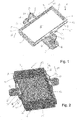
- an assembly 1 which has a housing 2 of a machine tool, which is shown only partially and schematically. Electronic components which are sensitive to dust and particles are provided in the housing 2. In order to protect them at least in some areas, the assembly 1 has a holding device 5 with a holding device 8 provided for arranging and holding the electronic components.
- the receiving device 8 is formed here with a substantially plate-shaped and in this case rectangular basic body 9, with four side walls 10, 11, 12, 13 bordering an edge region of the basic body 9 perpendicular to the basic body 9, which here are embodied integrally with the basic body 9 are.
- the receiving device 8 is cup-shaped here, an interior 15 being delimited by the base body 9 and the side walls 10, 11, 12, 13, in which the electronic components can be arranged and are at least partially protected from external influences.
- the housing 2 In order to be able to arrange the receiving device 5 on the housing 2, the housing 2 here has two fastening domes 17, 18 or screw-on domes, each of which is designed with an internal thread.
- the receiving device 8 has here on the side wall 10 a displacement mechanism 20 designed as a rail, which in the present case extends essentially over the entire longitudinal extent of the side wall 10.
- the rail 20 has a T-shaped profile with a web 22 projecting from the side wall 10 and a leg 21 arranged essentially parallel to the side wall 10 and connected to the web 22.
- the rail 20 is designed integrally with the receiving device 8.
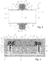
- a displacement device 25 is displaceably mounted on the rail 20, the displacement device 25 according to one in cross section Fig. 4 the rail 20 has at least partially encompassing region 26.
- the area 26 is designed with two hook elements 27, 28, the upper hook element 27 corresponding to the leg 21 of the rail 20 in the view Fig. 4 from above and the lower hook element 28 according to the leg 21 in the view Fig. 4 encompasses at least partially from below.
- the hook elements 27, 28 are arranged relative to one another and relative to the rail 20 such that the hook elements 27, 28 and thus the displacement device 25 can be displaced relative to the rail 20.
- a blocking device 30 with an area 31 is also displaceably mounted on the rail 20, the blocking device 30 having an upper hook element 32 and a lower hook element 33, comparable to the displacement device 25, each of which interacts with the leg 21 of FIG Rail 20 are executed.
- the hook elements 32, 33 of the blocking device 30 are at a greater distance from one another in the direction of extension ER of the leg 21 than the hook elements 27 and 28 of the displacement device 25, so that either the upper hook element 27 or the lower hook element 28 in the direction of extension ER of the T-shaped leg 21 can rest against the leg 21 and the blocking device 30 can thus be displaced perpendicular to the longitudinal direction LR of the rail 20 in the direction of extension ER of the leg 21 relative to the rail 20.
- the displacement device 25 has two regions 35, 36, each interacting with the rail 20, the region 31 of the blocking device 30 interacting with the rail 20, as in particular in FIG Fig. 3 can be seen in more detail, is arranged in the longitudinal direction LR of the rail 20 between the first region 35 and the second region 36 of the displacement device 25.
- the blocking device 25 has two here, for example in FIG Fig. 3 Grooves 38, 39, which run in more detail and extend in the direction of extension ER of the leg 21, in each of which a pin-shaped region 41 or 42 of the displacement device 25 is guided.
- the displacement device 25 also has a coupling area 44 which is designed to cooperate with the fastening dome 17 of the housing 2.
- the blocking device 30 has an essentially cylindrical coupling area 46, with which the blocking device 30 is arranged in an essentially hollow cylindrical connecting area 48 of the displacement device 25.
- Mutually facing wall areas of the coupling area 46 of the blocking device 30 and the coupling area 44 of the displacement device 25 can be shown in the illustration according to FIG Fig. 4 be tapered downwards.
- Both the coupling area 46 of the blocking device 30 and also the coupling area 44 and the connection area 48 of the displacement device 25 each have a through opening or through hole.
- a fastening device 50 which is embodied here as a screw, is provided, which according to FIG Fig. 4 is guided from above through the through bores of the blocking device 30 and the displacement device 25 and is in engagement with the internal thread of the fastening dome 17.
- a head 51 of the screw 50 lies against a shoulder of the blocking device 30.
- the receiving device 8 has, on the side wall 12 opposite the side wall 10, a further displacement mechanism 58 designed as a rail, which also has a further displacement device 59, a further blocking device 60 and a further fastening device 61 the dome 18 cooperates.
- a further displacement mechanism 58 designed as a rail
- the receiving device 8 has, on the side wall 12 opposite the side wall 10, a further displacement mechanism 58 designed as a rail, which also has a further displacement device 59, a further blocking device 60 and a further fastening device 61 the dome 18 cooperates.
- the blocking device 30 is in a position in which the displacement device 25 can be displaced in the longitudinal direction LR relative to the receiving device 8.
- the lower hook element 33 lies essentially against the T-shaped leg 21 of the rail 20 and a lower surface of the coupling region 46 of the blocking device 30 in the extension direction ER is spaced apart from the fastening dome 17.
- the screw 50 is not yet completely screwed to the fastening dome 17.
- the screw 61 is completely screwed into the fastening dome 18.
- the upper hook element 32 of the blocking device 60 is in contact with the leg 21 of the rail 20 and clamped relative to it, so that a displacement of the displacement device 59 relative to the rail 20 and thus the receiving device 8 is prevented.
- the blocking device 60 lies here with the lower surface 47 of the coupling region 46 on the fastening dome 18.
- the screws 50, 61 can for example first be brought into engagement with the respective fastening dome 17 or 18, the lower hook element 33 of the blocking devices 30 or 61 in contact with the respective one Rail 20 or 58 is. In this state, a position of the receiving device 8 with respect to the displacement device 25 or 59 and thus with respect to the fastening domes 17, 18 can be set to the desired extent. Subsequently, by further tightening the screws 50, 61, the blocking devices 30 and 60 can be wedged or clamped relative to the rails 20 and 58, so that the receiving device 8 is securely fixed relative to the fastening domes 17, 18.
Landscapes
- Engineering & Computer Science (AREA)
- Mechanical Engineering (AREA)
- Connection Of Plates (AREA)
- Casings For Electric Apparatus (AREA)
Priority Applications (5)
| Application Number | Priority Date | Filing Date | Title |
|---|---|---|---|
| EP18211856.2A EP3666474A1 (fr) | 2018-12-12 | 2018-12-12 | Dispositif de rangement pour un dispositif électronique et module |
| PCT/EP2019/082567 WO2020120124A1 (fr) | 2018-12-12 | 2019-11-26 | Dispositif de réception pour un système électronique et module |
| US17/295,177 US20220009080A1 (en) | 2018-12-12 | 2019-11-26 | Receiving apparatus for an electronic device and assembly |
| EP19806270.5A EP3894141B1 (fr) | 2018-12-12 | 2019-11-26 | Dispositif de rangement pour un dispositif électronique et module |
| CN201980075621.7A CN113165160A (zh) | 2018-12-12 | 2019-11-26 | 用于电子装置和组件的接纳设备 |
Applications Claiming Priority (1)
| Application Number | Priority Date | Filing Date | Title |
|---|---|---|---|
| EP18211856.2A EP3666474A1 (fr) | 2018-12-12 | 2018-12-12 | Dispositif de rangement pour un dispositif électronique et module |
Publications (1)
| Publication Number | Publication Date |
|---|---|
| EP3666474A1 true EP3666474A1 (fr) | 2020-06-17 |
Family
ID=64949026
Family Applications (2)
| Application Number | Title | Priority Date | Filing Date |
|---|---|---|---|
| EP18211856.2A Withdrawn EP3666474A1 (fr) | 2018-12-12 | 2018-12-12 | Dispositif de rangement pour un dispositif électronique et module |
| EP19806270.5A Active EP3894141B1 (fr) | 2018-12-12 | 2019-11-26 | Dispositif de rangement pour un dispositif électronique et module |
Family Applications After (1)
| Application Number | Title | Priority Date | Filing Date |
|---|---|---|---|
| EP19806270.5A Active EP3894141B1 (fr) | 2018-12-12 | 2019-11-26 | Dispositif de rangement pour un dispositif électronique et module |
Country Status (4)
| Country | Link |
|---|---|
| US (1) | US20220009080A1 (fr) |
| EP (2) | EP3666474A1 (fr) |
| CN (1) | CN113165160A (fr) |
| WO (1) | WO2020120124A1 (fr) |
Citations (3)
| Publication number | Priority date | Publication date | Assignee | Title |
|---|---|---|---|---|
| US4971234A (en) * | 1990-01-12 | 1990-11-20 | Hay Peter B | Pivotable storage unit for vehicles |
| US5056661A (en) * | 1989-04-17 | 1991-10-15 | Alfiero Balzano | Tool caddy |
| US6964545B1 (en) * | 2003-03-27 | 2005-11-15 | Languasco Ronald S | Apparatus including flash light and bit holder for attachment to an electric drill |
Family Cites Families (21)
| Publication number | Priority date | Publication date | Assignee | Title |
|---|---|---|---|---|
| US3664716A (en) * | 1970-12-22 | 1972-05-23 | Gen Fireproofing Co The | Drawer suspension |
| US5129613A (en) * | 1989-03-29 | 1992-07-14 | Union Oil Company Of California | Fixture for attaching contact material |
| US5884681A (en) * | 1997-12-29 | 1999-03-23 | Nickles; Steven R. | Method and apparatus for connecting or securing a power tool with respect to a work surface |
| DE102005054252B4 (de) * | 2005-11-11 | 2009-04-02 | Sew-Eurodrive Gmbh & Co. Kg | System, umfassend Profilschiene und Box und mindestens einen Halter, und Verfahren zur Befestigung einer Box an einer Profilschiene |
| DE202006016486U1 (de) * | 2006-10-24 | 2006-12-28 | Phoenix Contact Gmbh & Co. Kg | Elektronikgehäuse |
| DE102006057766B4 (de) * | 2006-12-07 | 2010-02-04 | Siemens Ag | Befestigungsvorrichtung von Elektronikmodulen auf Tragschiene |
| US8066239B2 (en) * | 2009-06-15 | 2011-11-29 | Rockwell Automation Technologies, Inc. | Integrated DIN rail attachment feature for superior attachment |
| DE102009059014A1 (de) * | 2009-12-17 | 2011-06-22 | Phoenix Contact GmbH & Co. KG, 32825 | Vorrichtung zum Befestigen einer Moduleinheit auf einer Tragschiene |
| CN201821007U (zh) * | 2010-05-03 | 2011-05-04 | Abb股份公司 | 带有快速固定装置的电气安装开关设备 |
| DE102010032927A1 (de) * | 2010-07-30 | 2012-02-02 | Hazet-Werk Hermann Zerver Gmbh & Co. Kg. | Verschlussmechanismus |
| AT512009B1 (de) * | 2011-10-13 | 2014-04-15 | Metzler Gmbh & Co Kg | Einrichtung zum lagern von utensilien, insbesondere werkzeug |
| EP2626962A1 (fr) * | 2012-02-13 | 2013-08-14 | Siemens Aktiengesellschaft | Fixation de serrage pour la fixation d'un boîtier sur un rail |
| US10047546B2 (en) * | 2013-02-14 | 2018-08-14 | Keter Plastic Ltd. | Cabinet of storage units |
| DE102014007828B4 (de) * | 2014-06-02 | 2024-04-18 | Wolfgang Held | Vorrichtung zum Ausrichten einer aus Boden, zwei Seitenwänden, Rückwand und Blende bestehenden Schublade in eine horizontale Einschub-Endstellung in einem Möbelkorpus |
| CN204277983U (zh) * | 2014-11-12 | 2015-04-22 | 北汽福田汽车股份有限公司 | 零件定位料箱组件 |
| GB2548837A (en) * | 2016-03-29 | 2017-10-04 | Kao Jui-Chien | Hand tool frame |
| CN205630547U (zh) * | 2016-04-29 | 2016-10-12 | 天津市金百利模具有限公司 | 一种大型管道密封圈模具存放装置 |
| KR101724068B1 (ko) * | 2017-01-24 | 2017-04-06 | 주식회사 탑시스템 | 천장형 디스플레이 위치 조절장치 |
| CN207240159U (zh) * | 2017-08-22 | 2018-04-17 | 天津市宏达铸造厂 | 一种宽度可调的工装存放装置 |
| CN108581991B (zh) * | 2018-04-08 | 2021-02-05 | 南京晨光集团有限责任公司 | 一种用于电子元器件的型号分类设备 |
| DE102018206898A1 (de) * | 2018-05-04 | 2019-11-07 | Carl Zeiss Microscopy Gmbh | Vorrichtung und Verfahren zur Nachverfolgung mikroskopischer Proben |
-
2018
- 2018-12-12 EP EP18211856.2A patent/EP3666474A1/fr not_active Withdrawn
-
2019
- 2019-11-26 EP EP19806270.5A patent/EP3894141B1/fr active Active
- 2019-11-26 WO PCT/EP2019/082567 patent/WO2020120124A1/fr unknown
- 2019-11-26 CN CN201980075621.7A patent/CN113165160A/zh active Pending
- 2019-11-26 US US17/295,177 patent/US20220009080A1/en active Pending
Patent Citations (3)
| Publication number | Priority date | Publication date | Assignee | Title |
|---|---|---|---|---|
| US5056661A (en) * | 1989-04-17 | 1991-10-15 | Alfiero Balzano | Tool caddy |
| US4971234A (en) * | 1990-01-12 | 1990-11-20 | Hay Peter B | Pivotable storage unit for vehicles |
| US6964545B1 (en) * | 2003-03-27 | 2005-11-15 | Languasco Ronald S | Apparatus including flash light and bit holder for attachment to an electric drill |
Also Published As
| Publication number | Publication date |
|---|---|
| EP3894141B1 (fr) | 2022-09-14 |
| CN113165160A (zh) | 2021-07-23 |
| WO2020120124A1 (fr) | 2020-06-18 |
| US20220009080A1 (en) | 2022-01-13 |
| EP3894141A1 (fr) | 2021-10-20 |
Similar Documents
| Publication | Publication Date | Title |
|---|---|---|
| DE102012003617B4 (de) | Vorrichtung aus einem Gehäuse für ein Steuergerät und einem Befestigungselement | |
| DE102010011986B4 (de) | Handgeführtes Arbeitsgerät | |
| WO2016128169A1 (fr) | Ensemble de plusieurs pieds encliquetables pour module et module | |
| DE102014102793B4 (de) | Befestigungselement für einen Stromsensor | |
| DE19733375B4 (de) | Vorrichtung zur Branderkennung | |
| DE102013110788B4 (de) | Sammelschienen-Adapter | |
| DE102020124448A1 (de) | Verbindungssystem zum Verbinden von mindestens zwei, insbesondere plattenartigen, Elementen; Anordnung mit einem derartigen Verbindungssystem | |
| EP3894141B1 (fr) | Dispositif de rangement pour un dispositif électronique et module | |
| EP4080069B1 (fr) | Système de fixation | |
| EP1904751A1 (fr) | Dispositif pour fixer de maniere antivibratile au moins un objet sur un element support | |
| DE19734601A1 (de) | Lochscheibe | |
| EP3535824B1 (fr) | Support de jeu de barres et ensemble correspondant | |
| DE102006029807B4 (de) | Befestigungsvorrichtung mit Schwenkbasis | |
| DE102017109483B4 (de) | Drehverschluss | |
| DE102016107858B4 (de) | Heckblendenanordnung eines Kraftfahrzeugs | |
| WO2006089521A1 (fr) | Systeme de fixation pour au moins un composant fluidique d'un ensemble de chromatographie | |
| DE10305931B4 (de) | Vorrichtung zur Befestigung von Bauteilen elektrischer Zähler- und Verteilereinrichtungen an einer Trägerschiene | |
| DE7700238U1 (de) | Mehrfachschutzkontaktsteckdose | |
| DE102018128840B3 (de) | Montagestrukturteil | |
| DE102009030887B4 (de) | Ventilanordnung | |
| DE2629090A1 (de) | Befestigungsvorrichtung mit verriegelungsfunktion fuer eine auf einer tragschiene angeordnete elektrische baugruppe | |
| DE102008046951B4 (de) | Halterung für Gehäuse für elektronische Bauteile | |
| DE102021109165A1 (de) | Befestiger für eine Schraubbefestigung an einer Montageschiene und Befestigungsanordnung mit einem solchen Befestiger | |
| DE202019100965U1 (de) | Vorrichtung zur Anbringung einer Vermessungsmarke an einem Ankerbolzen | |
| DE102012004260A1 (de) | Unterputzeinsatz eines elektrischen / elektronischen Installationsgerätes der Hausinstallationstechnik mit Gerätesockel und Tragring |
Legal Events
| Date | Code | Title | Description |
|---|---|---|---|
| PUAI | Public reference made under article 153(3) epc to a published international application that has entered the european phase |
Free format text: ORIGINAL CODE: 0009012 |
|
| STAA | Information on the status of an ep patent application or granted ep patent |
Free format text: STATUS: THE APPLICATION HAS BEEN PUBLISHED |
|
| AK | Designated contracting states |
Kind code of ref document: A1 Designated state(s): AL AT BE BG CH CY CZ DE DK EE ES FI FR GB GR HR HU IE IS IT LI LT LU LV MC MK MT NL NO PL PT RO RS SE SI SK SM TR |
|
| AX | Request for extension of the european patent |
Extension state: BA ME |
|
| STAA | Information on the status of an ep patent application or granted ep patent |
Free format text: STATUS: THE APPLICATION IS DEEMED TO BE WITHDRAWN |
|
| 18D | Application deemed to be withdrawn |
Effective date: 20201218 |