EP3666442A1 - Schweisssystem und verfahren - Google Patents
Schweisssystem und verfahren Download PDFInfo
- Publication number
- EP3666442A1 EP3666442A1 EP19203502.0A EP19203502A EP3666442A1 EP 3666442 A1 EP3666442 A1 EP 3666442A1 EP 19203502 A EP19203502 A EP 19203502A EP 3666442 A1 EP3666442 A1 EP 3666442A1
- Authority
- EP
- European Patent Office
- Prior art keywords
- controller
- circuit
- welder
- data
- weld
- Prior art date
- Legal status (The legal status is an assumption and is not a legal conclusion. Google has not performed a legal analysis and makes no representation as to the accuracy of the status listed.)
- Granted
Links
Images

Classifications
-
- B—PERFORMING OPERATIONS; TRANSPORTING
- B23—MACHINE TOOLS; METAL-WORKING NOT OTHERWISE PROVIDED FOR
- B23K—SOLDERING OR UNSOLDERING; WELDING; CLADDING OR PLATING BY SOLDERING OR WELDING; CUTTING BY APPLYING HEAT LOCALLY, e.g. FLAME CUTTING; WORKING BY LASER BEAM
- B23K9/00—Arc welding or cutting
- B23K9/095—Monitoring or automatic control of welding parameters
- B23K9/0953—Monitoring or automatic control of welding parameters using computing means
-
- B—PERFORMING OPERATIONS; TRANSPORTING
- B23—MACHINE TOOLS; METAL-WORKING NOT OTHERWISE PROVIDED FOR
- B23K—SOLDERING OR UNSOLDERING; WELDING; CLADDING OR PLATING BY SOLDERING OR WELDING; CUTTING BY APPLYING HEAT LOCALLY, e.g. FLAME CUTTING; WORKING BY LASER BEAM
- B23K20/00—Non-electric welding by applying impact or other pressure, with or without the application of heat, e.g. cladding or plating
- B23K20/10—Non-electric welding by applying impact or other pressure, with or without the application of heat, e.g. cladding or plating making use of vibrations, e.g. ultrasonic welding
-
- B—PERFORMING OPERATIONS; TRANSPORTING
- B23—MACHINE TOOLS; METAL-WORKING NOT OTHERWISE PROVIDED FOR
- B23K—SOLDERING OR UNSOLDERING; WELDING; CLADDING OR PLATING BY SOLDERING OR WELDING; CUTTING BY APPLYING HEAT LOCALLY, e.g. FLAME CUTTING; WORKING BY LASER BEAM
- B23K31/00—Processes relevant to this subclass, specially adapted for particular articles or purposes, but not covered by any single one of main groups B23K1/00 - B23K28/00
- B23K31/12—Processes relevant to this subclass, specially adapted for particular articles or purposes, but not covered by any single one of main groups B23K1/00 - B23K28/00 relating to investigating the properties, e.g. the weldability, of materials
- B23K31/125—Weld quality monitoring
-
- B—PERFORMING OPERATIONS; TRANSPORTING
- B23—MACHINE TOOLS; METAL-WORKING NOT OTHERWISE PROVIDED FOR
- B23K—SOLDERING OR UNSOLDERING; WELDING; CLADDING OR PLATING BY SOLDERING OR WELDING; CUTTING BY APPLYING HEAT LOCALLY, e.g. FLAME CUTTING; WORKING BY LASER BEAM
- B23K9/00—Arc welding or cutting
- B23K9/0026—Arc welding or cutting specially adapted for particular articles or work
-
- B—PERFORMING OPERATIONS; TRANSPORTING
- B23—MACHINE TOOLS; METAL-WORKING NOT OTHERWISE PROVIDED FOR
- B23K—SOLDERING OR UNSOLDERING; WELDING; CLADDING OR PLATING BY SOLDERING OR WELDING; CUTTING BY APPLYING HEAT LOCALLY, e.g. FLAME CUTTING; WORKING BY LASER BEAM
- B23K9/00—Arc welding or cutting
- B23K9/007—Spot arc welding
-
- B—PERFORMING OPERATIONS; TRANSPORTING
- B23—MACHINE TOOLS; METAL-WORKING NOT OTHERWISE PROVIDED FOR
- B23K—SOLDERING OR UNSOLDERING; WELDING; CLADDING OR PLATING BY SOLDERING OR WELDING; CUTTING BY APPLYING HEAT LOCALLY, e.g. FLAME CUTTING; WORKING BY LASER BEAM
- B23K9/00—Arc welding or cutting
- B23K9/095—Monitoring or automatic control of welding parameters
- B23K9/0956—Monitoring or automatic control of welding parameters using sensing means, e.g. optical
-
- B—PERFORMING OPERATIONS; TRANSPORTING
- B23—MACHINE TOOLS; METAL-WORKING NOT OTHERWISE PROVIDED FOR
- B23K—SOLDERING OR UNSOLDERING; WELDING; CLADDING OR PLATING BY SOLDERING OR WELDING; CUTTING BY APPLYING HEAT LOCALLY, e.g. FLAME CUTTING; WORKING BY LASER BEAM
- B23K9/00—Arc welding or cutting
- B23K9/10—Other electric circuits therefor; Protective circuits; Remote controls
- B23K9/1006—Power supply
- B23K9/1043—Power supply characterised by the electric circuit
- B23K9/1056—Power supply characterised by the electric circuit by using digital means
- B23K9/1062—Power supply characterised by the electric circuit by using digital means with computing means
-
- B—PERFORMING OPERATIONS; TRANSPORTING
- B23—MACHINE TOOLS; METAL-WORKING NOT OTHERWISE PROVIDED FOR
- B23K—SOLDERING OR UNSOLDERING; WELDING; CLADDING OR PLATING BY SOLDERING OR WELDING; CUTTING BY APPLYING HEAT LOCALLY, e.g. FLAME CUTTING; WORKING BY LASER BEAM
- B23K9/00—Arc welding or cutting
- B23K9/10—Other electric circuits therefor; Protective circuits; Remote controls
- B23K9/1087—Arc welding using remote control
-
- G—PHYSICS
- G06—COMPUTING OR CALCULATING; COUNTING
- G06Q—INFORMATION AND COMMUNICATION TECHNOLOGY [ICT] SPECIALLY ADAPTED FOR ADMINISTRATIVE, COMMERCIAL, FINANCIAL, MANAGERIAL OR SUPERVISORY PURPOSES; SYSTEMS OR METHODS SPECIALLY ADAPTED FOR ADMINISTRATIVE, COMMERCIAL, FINANCIAL, MANAGERIAL OR SUPERVISORY PURPOSES, NOT OTHERWISE PROVIDED FOR
- G06Q50/00—Information and communication technology [ICT] specially adapted for implementation of business processes of specific business sectors, e.g. utilities or tourism
- G06Q50/04—Manufacturing
-
- B—PERFORMING OPERATIONS; TRANSPORTING
- B23—MACHINE TOOLS; METAL-WORKING NOT OTHERWISE PROVIDED FOR
- B23K—SOLDERING OR UNSOLDERING; WELDING; CLADDING OR PLATING BY SOLDERING OR WELDING; CUTTING BY APPLYING HEAT LOCALLY, e.g. FLAME CUTTING; WORKING BY LASER BEAM
- B23K2101/00—Articles made by soldering, welding or cutting
- B23K2101/36—Electric or electronic devices
-
- G—PHYSICS
- G05—CONTROLLING; REGULATING
- G05B—CONTROL OR REGULATING SYSTEMS IN GENERAL; FUNCTIONAL ELEMENTS OF SUCH SYSTEMS; MONITORING OR TESTING ARRANGEMENTS FOR SUCH SYSTEMS OR ELEMENTS
- G05B2219/00—Program-control systems
- G05B2219/30—Nc systems
- G05B2219/45—Nc applications
- G05B2219/45135—Welding
-
- G—PHYSICS
- G05—CONTROLLING; REGULATING
- G05B—CONTROL OR REGULATING SYSTEMS IN GENERAL; FUNCTIONAL ELEMENTS OF SUCH SYSTEMS; MONITORING OR TESTING ARRANGEMENTS FOR SUCH SYSTEMS OR ELEMENTS
- G05B23/00—Testing or monitoring of control systems or parts thereof
- G05B23/02—Electric testing or monitoring
- G05B23/0205—Electric testing or monitoring by means of a monitoring system capable of detecting and responding to faults
- G05B23/0218—Electric testing or monitoring by means of a monitoring system capable of detecting and responding to faults characterised by the fault detection method dealing with either existing or incipient faults
- G05B23/0224—Process history based detection method, e.g. whereby history implies the availability of large amounts of data
- G05B23/0227—Qualitative history assessment, whereby the type of data acted upon, e.g. waveforms, images or patterns, is not relevant, e.g. rule based assessment; if-then decisions
- G05B23/0235—Qualitative history assessment, whereby the type of data acted upon, e.g. waveforms, images or patterns, is not relevant, e.g. rule based assessment; if-then decisions based on a comparison with predetermined threshold or range, e.g. "classical methods", carried out during normal operation; threshold adaptation or choice; when or how to compare with the threshold
Definitions
- This disclosure generally relates to a welding system, and more particularly relates to a welding system that is remotely monitored.
- Fig. 1 illustrates a welding system 10, hereafter referred to as the system 10.
- the system 10 in an improvement over other welding systems because the system 10 prevents a welder 12 from welding until tests are approved.
- the system 10 includes the welder 12 configured to create an assembly 14 by forming a weld-joint 16 between electrical-components 18.
- the welder 12 may be any welder 12 capable of creating a metallurgical bond, and in the example illustrated in Fig. 1 the welder 12 is a sonic-welder.
- the electrical-components 18 are wire-cables that are welded to one, another, creating a splice-joint.
- the electrical-components 18 are wire-cables that are welded electrical-terminals.
- the system 10 also includes a human-machine-interface 20 (HMI 20) configured to receive an input 22 to the system 10 from an operator (e.g. a human operator of the system 10) and display instructions 24 from the system 10 to the operator.
- the HMI 20 may be any HMI 20 and preferably is a display monitor (i.e., a cathode ray tube (CRT), a liquid crystal display (LCD), plasma display, light emitting diode (LED) display, or an organic light emitting diode (OLED) display for displaying information to the operator).
- a display monitor i.e., a cathode ray tube (CRT), a liquid crystal display (LCD), plasma display, light emitting diode (LED) display, or an organic light emitting diode (OLED) display for displaying information to the operator.
- CTR cathode ray tube
- LCD liquid crystal display
- LED light emitting diode
- OLED organic light emitting diode
- the HMI 20 includes an input-device (not shown), including alphanumeric and other keys, and a cursor-control-device (not shown) for communicating direction information and command selections to the system 10 and for controlling cursor movement on the display (e.g., a mouse, a trackball, a touch-enabled display, or cursor direction keys).
- an input-device including alphanumeric and other keys
- a cursor-control-device for communicating direction information and command selections to the system 10 and for controlling cursor movement on the display (e.g., a mouse, a trackball, a touch-enabled display, or cursor direction keys).
- the system 10 also includes an identification-device 26 configured to create a label 28 indicative of an identity 30 of the assembly 14.
- the identity 30 may include part numbers associated with the electrical-components 18 of the assembly 14, and/or metadata associated with the assembly 14.
- the identification-device 26 is a printer that prints a character (e.g., a bar code, part number, etc.) on a film configured to be attached to the assembly 14.
- the identification-device 26 is a radio frequency identification (RFID) chip encoder that encodes an RFID chip that is configured to be attached to the assembly 14.
- RFID radio frequency identification
- the system 10 also includes a test-device 32 configured to produce test-data 34 indicative of a characteristic of the weld-joint 16.
- the test-data 34 includes a weld-strength value 36 that may be measured by a tensile-test, or may be measured by a bend-test, both of which are destructive tests.
- the test-device 32 is a tensile-test machine.
- the test-device may measure a height and a width of the weld-joint 16 or may perform imaging, e.g. ultrasonic or x-ray imaging of the weld-joint 16.
- the system 10 also includes a memory 38 configured to store welder-process-data 40 generated by the welder 12 that is associated with the formation of the weld-joint 16.
- the memory 38 may reside in a cloud computing environment (i.e., "cloud” storage - not shown), or may reside locally with the welder 12.
- the memory 38 may be hard wired to the system 10, or may communicate through a communications channel configured to transmit digital data collected from the system 10.
- the welder-process-data 40 includes a cross-sectional area of the electrical-components 18, a pressure of a weld-head, an amplitude of the weld-current, a total energy delivered to the weld-joint 16, a weld compacting height, a weld compacting height reference, a weld-time, a weld-time-reference, a weld-height, a weld-height-reference, a weld-tool life, a weld-recipe, a weld-width, and a splice-sequence.
- the welder-process-data 40 is associated (i.e.
- the memory 38 may be any non-transitory media that store the test-data 34.
- the memory 38 includes non-volatile-memory and/or volatile-memory.
- Non-volatile-memory includes, for example, optical disks, magnetic disks, solid-state drives, or three-dimensional cross point memory.
- Volatile-memory includes dynamic-memory.
- storage-media include, for example, a floppy disk, a flexible disk, hard disk, solid-state drive, magnetic tape, or any other magnetic data storage medium, a CD-ROM, any other optical data storage medium, any physical medium with patterns of holes, a RAM, a PROM, and EPROM, a FLASH-EPROM, NV-RAM, or any other memory-chip or cartridge.
- the storage medium may be local or cloud-based.
- the system 10 also includes a controller-circuit 42 in communication with the welder 12, the HMI 20, the identification-device 26, the test-device 32, and the memory 38.
- the controller-circuit 42 is a special-purpose computing device.
- the special-purpose computing device is hard-wired to perform the techniques or includes digital electronic devices such as one or more application-specific integrated circuits (ASICs) or field programmable gate arrays (FPGAs) that are persistently programmed to perform the techniques, or may include one or more general purpose hardware processors programmed to perform the techniques pursuant to program instructions in firmware, memory, other storage, or a combination.
- ASICs application-specific integrated circuits
- FPGAs field programmable gate arrays
- Such special-purpose computing devices may also combine custom hard-wired logic, ASICs, or FPGAs with custom programming to accomplish the techniques.
- the special-purpose computing devices are desktop computer systems, portable computer systems, handheld devices, network devices or any other device that incorporates hard-wired and/or program logic to implement the techniques.
- the controller-circuit 42 includes a bus (not specifically shown) or other communication mechanism for communicating information, and a hardware processor coupled with a bus for processing information.
- the hardware processor is, for example, a general-purpose microprocessor.
- the controller-circuit 42 also includes a main-memory (not shown), such as a random-access memory (RAM) or other dynamic storage device, coupled to the bus for storing information and instructions to be executed by processor.
- the main-memory is used for storing temporary variables or other intermediate information during execution of instructions to be executed by the processor.
- Such instructions when stored in non-transitory storage media accessible to the processor, render the controller-circuit 42 into a special-purpose machine that is customized to perform the operations specified in the instructions.
- the controller-circuit 42 further includes a read-only-memory (ROM) or other static storage device coupled to the bus for storing static information and instructions for the processor.
- ROM read-only-memory
- a storage device such as a magnetic disk, optical disk, solid-state drive, or three-dimensional cross point memory is provided and coupled to the bus for storing information and instructions.
- the techniques herein are performed by the controller-circuit 42 in response to the processor executing one or more sequences of one or more instructions contained in the main-memory. Such instructions are read into the main-memory from another storage medium, such as the storage device. Execution of the sequences of instructions contained in the main-memory causes the processor to perform the process steps described herein. In alternative embodiments, hard-wired circuitry is used in place of or in combination with software instructions.
- Storage media is distinct from but may be used in conjunction with transmission media.
- Transmission media participates in transferring information between storage media.
- transmission media includes coaxial cables, copper wire and fiber optics, including the wires that comprise the bus.
- transmission media can also take the form of acoustic, electromagnetic, or light waves, such as those generated during radio-wave and infrared data communications.
- various forms of media are involved in carrying one or more sequences of one or more instructions to the processor for execution.
- the instructions are initially carried on a magnetic disk or solid-state drive of a remote computer.
- the remote computer loads the instructions into its dynamic memory and sends the instructions over a telephone line using a modem.
- a modem (not shown) local to the controller-circuit 42 receives the data on the telephone line and uses an infrared transmitter to convert the data to an infrared signal.
- An infrared detector receives the data carried in the infrared signal and appropriate circuitry places the data on the bus.
- the bus carries the data to the main-memory, from which the processor retrieves and executes the instructions.
- the instructions received by the main-memory may optionally be stored on the storage device either before or after execution by processor.
- the controller-circuit 42 also includes a communication interface (not shown) coupled to the bus.
- the communication interface provides a two-way data communication coupling to a network link that is connected to a local network.
- the communication interface is an integrated service digital network (ISDN) card, cable modem, satellite modem, or a modem to provide a data communication connection to a corresponding type of telephone line.
- ISDN integrated service digital network
- the communication interface is a local area network (LAN) card to provide a data communication connection to a compatible LAN.
- LAN local area network
- wireless links are also implemented.
- the communication interface sends and receives electrical, electromagnetic, or optical signals that carry digital data streams representing various types of information.
- the network link typically provides data communication through one or more networks to other data devices.
- the network link provides a connection through the local network to a host computer or to a cloud data center or equipment operated by an Internet Service Provider (ISP).
- ISP Internet Service Provider
- the ISP in turn provides data communication services through the world-wide packet data communication network now commonly referred to as the "Internet".
- the local network and Internet both use electrical, electromagnetic or optical signals that carry digital data streams.
- the signals through the various networks and the signals on the network link and through the communication interface, which carry the digital data to and from the controller-circuit 42, are example forms of transmission media.
- the network contains the cloud or a part of the cloud described above.
- the controller-circuit 42 sends messages and receives data, including program code, through the network(s), the network link, and the communication interface.
- the controller-circuit 42 receives code for processing.
- the received code is executed by the processor as it is received, and/or stored in storage device, or other non-volatile storage for later execution.
- the controller-circuit 42 is configured to activate the welder 12 to create the assembly 14 and store the welder-process-data 40 in the memory 38 linked to the identity 30.
- the controller-circuit 42 determines whether the welder-process-data 40 violates a quality-metric 44 that is stored in the memory 38 by comparing the welder-process-data 40 to the quality-metric 44.
- the quality-metric 44 includes process data based metrics, as well as environmental metrics that are independent of the process data based metrics at a given instant (e.g., time between process parts, every specific number of parts, etc).
- the controller-circuit 42 also monitors the welder-process-data 40 in real-time using a logic-algorithm to establish limit violation trends.
- the controller-circuit 42 activates the welder 12 to create a predetermined number of assemblies 14 in order to generate a sample size representative of the population of the assemblies 14.
- the predetermined number of assemblies 14 may be any quantity defined by the user, and is preferably greater than 30 assemblies 14.
- the controller-circuit 42 is further configured to determine a number (i.e. a quantity, count, etc.) of violating-weld-joints 46 and activate an alert-device 50 to alert the operator to the violating-weld-joints 46.
- the alert-device 50 is preferably an indicia that is displayed to the operator through the HMI 20 and may include text, light, sound, or any combination thereof.
- the controller-circuit 42 disables 48 the welder 12 when the number of violating-weld-joints 46 exceeds a threshold 52.
- the threshold 52 may be user defined and may be based on a quality control plan.
- the threshold 52 may be applied to any of the welder-process-data 40, as well as the environmental metrics described above.
- the controller-circuit 42 activates the identification-device 26 to create the label 28 and instructs the operator to attach the label 28 to the assemblies 14 having the violating-weld-joints 46. Once the assembly 14 is labeled the controller-circuit 42 instructs the operator to perform a test of the violating-weld-joints 46 with the test-device 32. The operator may link the test of the violating-weld-joints 46 to the identity 30 by entering the identity 30 into the system 10 by scanning the label 28 with a scanning-device (not shown) or by manually entering the identity 30 using the HMI 20.
- the controller-circuit 42 activates the identification-device 26 to create labels 28 for all of the predetermined number of assemblies 14 and instructs the operator to attach the labels 28 to all of the predetermined number of assemblies 14 and perform the test of all the weld-joints 16 with the test-device 32.
- the controller-circuit 42 stores the test-data 34 of the violating-weld-joints 46 in the memory 38 linked to the identity 30, enabling a real-time access to the test-data 34and welder-process-data 40 for the system 10.
- the controller-circuit 42 stores the test-data 34 of all of the predetermined number of assemblies 14 in the memory 38 linked to the identity 30, regardless of whether the weld-joints 16 are considered violating-weld-joints 46. This has the technical benefit of enabling part traceability throughout the process through a central-database.
- the system 10 further includes a remote-supervisor 54 in communication with the controller-circuit 42.
- the remote-supervisor 54 is also alerted by the alert-device 50 in accordance with the determination that the welder-process-data 40 violates the quality-metric 44.
- the remote-supervisor 54 may be a remote computer that is programmed to compare the welder-process-data 40 and the test-data 34 to the quality-metric 44 and make a determination whether to re-enable 56 the welder 12, whereby the controller-circuit 42 re-enables 56 the welder 12 based on an approval 58 by the remote-supervisor 54.
- the system 10 further includes a camera 60 in communication with the controller-circuit 42.
- the camera 60 is configured to render an image 62 of the weld-joint 16, wherein the controller-circuit 42 is further configured to store the image 62 in the memory 38 linked to the identity 30.
- the camera 60 may be any camera 60 that is capable of capturing a digital image 62 of the weld-joint 16 and preferably has a resolution of at least 4 megapixels.
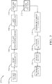
- Fig. 2 is a flow chart illustrating a welding method 100 using the system 10 illustrated in Fig. 1 .
- Step 102 ACTIVATE WELDER, includes activating a welder 12, with the controller-circuit 42, to create the assembly 14 by forming the weld-joint 16 between electrical-components 18.
- Step 104 STORE PROCESS-DATA, includes storing in the memory 38, with the controller-circuit 42, welder-process-data 40 associated with the weld-joint 16 linked to the identity 30 of the assembly 14.
- Step 106 DETERMINE VIOLATION, includes determining, with the controller-circuit 42, whether the welder-process-data 40 violates the quality-metric 44 as described above.
- Step 108 DETERMINE NUMBER OF VIOLATIONS, includes determining, with the controller-circuit 42, the number of violating-weld-joints 46.
- Step 110 ACTIVATE ALERT-DEVICE, includes activating, with the controller-circuit 42, the alert-device 50 alerting the operator to the violating-weld-joints 46.
- Step 112 DISABLE WELDER, includes disabling, with the controller-circuit 42, the welder 12 when the number of violating-weld-joints 46 is greater than the threshold 52 as described above.
- Step 114 ACTIVATE IDENTIFICATION-DEVICE, includes activating, with the controller-circuit 42, the identification-device 26 to create the label 28 indicative of the identity 30 of the assemblies 14 having the violating-weld-joints 46.
- Step 116 includes instructing, with the controller-circuit 42 through the HMI 20, the operator to attach the label 28 to the assemblies 14 having the violating-weld-joints 46.
- Step 118 PERFORM TESTS, includes instructing, with the controller-circuit 42 through the HMI 20, the operator to perform tests of the assemblies 14 having the violating-weld-joints 46 with the test-device 32, thereby producing test-data 34 indicative of a characteristic of the weld-joints 16.
- Step 120 STORE TEST-DATA, includes storing, with the controller-circuit 42, the test-data 34 in the memory 38 linked to the identity 30.
- the system 10 further includes the camera 60 in communication with the controller-circuit 42.
- the camera 60 renders the image 62 of the weld-joint 16, whereby the controller-circuit 42, stores the image 62 in the memory 38 linked to the identity 30.
- Step 122 RE-ENABLE WELDER, includes re-enabling 56, with the controller-circuit 42, the welder 12 based on the approval 58 by the remote-supervisor 54 in communication with the controller-circuit 42.
- the remote-supervisor 54 is also alerted by the alert-device 50 in accordance with the determination that the welder-process-data 40 violates the quality-metric 44, as described above.
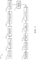
- Fig. 3 is another flow chart illustrating another welding method 200 using the system 10 illustrated in Fig. 1 .
- Step 202 ACTIVATE WELDER, includes activating the welder 12, with the controller-circuit 42, to create the predetermined number of assemblies 14 by forming the weld-joint 16 between electrical-components 18.
- Step 204 STORE PROCESS-DATA, includes storing in the memory 38, with the controller-circuit 42, welder-process-data 40 associated with the weld-joint 16 linked to the identities 30 of the predetermined number of assemblies 14.
- Step 206 ACTIVATE IDENTIFICATION-DEVICE, includes activating, with the controller-circuit 42, the identification-device 26 to create labels 28 indicative of the identities 30 of the predetermined number of assemblies 14.
- Step 208 includes instructing, with the controller-circuit 42 through the HMI 20, the operator to attach the labels 28 to the predetermined number of assemblies 14.
- Step 210 includes instructing, with the controller-circuit 42 through the HMI 20, the operator to perform tests of the predetermined number of assemblies 14 with the test-device 32, thereby producing test-data 34 indicative of a characteristic of the weld-joints 16.
- Step 212 STORE TEST-DATA, includes storing, with the controller-circuit 42, the test-data 34 in the memory 38 linked to the identity 30 of the predetermined number of assemblies 14.
- the system 10 further includes the camera 60 in communication with the controller-circuit 42.
- the camera 60 renders the image 62 of the weld-joints 16, whereby the controller-circuit 42, stores the images 62 in the memory 38 linked to the identities 30 of the predetermined number of assemblies 14.
- Step 214, DETERMINE NUMBER OF VIOLATIONS includes determining, with the controller-circuit 42, whether the welder-process-data 40 violates the quality-metric 44 as described above, and includes determining the number of violating-weld-joints 46.
- Step 216, ACTIVATE ALERT-DEVICE includes activating, with the controller-circuit 42, the alert-device 50 alerting the operator to the violating-weld-joints 46.
- Step 218, DISABLE WELDER includes disabling, with the controller-circuit 42, the welder 12 when the number of violating-weld-joints 46 is greater than the threshold 52 as described above.
- Step 220 RE-ENABLE WELDER, includes re-enabling 56, with the controller-circuit 42, the welder 12 based on the approval 58 by the remote-supervisor 54 in communication with the controller-circuit 42.
- the remote-supervisor 54 is also alerted by the alert-device 50 in accordance with the determination that the welder-process-data 40 violates the quality-metric 44, as described above.
- first contact could be termed a second contact
- second contact could be termed a first contact
- the first contact and the second contact are both contacts, but they are not the same contact.
- the terminology used in the description of the various described embodiments herein is for the purpose of describing particular embodiments only and is not intended to be limiting. As used in the description of the various described embodiments and the appended claims, the singular forms "a”, “an” and “the” are intended to include the plural forms as well, unless the context clearly indicates otherwise. It will also be understood that the term “and/or” as used herein refers to and encompasses any and all possible combinations of one or more of the associated listed items.
- the phrase “if it is determined” or “if [a stated condition or event] is detected” is, optionally, construed to mean “upon determining” or “in response to determining” or “upon detecting [the stated condition or event]” or “in response to detecting [the stated condition or event],” depending on the context.
Landscapes
- Engineering & Computer Science (AREA)
- Mechanical Engineering (AREA)
- Physics & Mathematics (AREA)
- Plasma & Fusion (AREA)
- Theoretical Computer Science (AREA)
- Quality & Reliability (AREA)
- Business, Economics & Management (AREA)
- General Health & Medical Sciences (AREA)
- Health & Medical Sciences (AREA)
- Economics (AREA)
- Manufacturing & Machinery (AREA)
- Human Resources & Organizations (AREA)
- Marketing (AREA)
- Primary Health Care (AREA)
- Strategic Management (AREA)
- Tourism & Hospitality (AREA)
- General Business, Economics & Management (AREA)
- General Physics & Mathematics (AREA)
- General Factory Administration (AREA)
- Arc Welding Control (AREA)
Applications Claiming Priority (1)
| Application Number | Priority Date | Filing Date | Title |
|---|---|---|---|
| US16/164,998 US10639737B1 (en) | 2018-10-19 | 2018-10-19 | Welding system and method |
Publications (2)
| Publication Number | Publication Date |
|---|---|
| EP3666442A1 true EP3666442A1 (de) | 2020-06-17 |
| EP3666442B1 EP3666442B1 (de) | 2025-05-21 |
Family
ID=68281139
Family Applications (1)
| Application Number | Title | Priority Date | Filing Date |
|---|---|---|---|
| EP19203502.0A Active EP3666442B1 (de) | 2018-10-19 | 2019-10-16 | Schweisssystem und verfahren |
Country Status (3)
| Country | Link |
|---|---|
| US (2) | US10639737B1 (de) |
| EP (1) | EP3666442B1 (de) |
| CN (1) | CN111079246B (de) |
Families Citing this family (1)
| Publication number | Priority date | Publication date | Assignee | Title |
|---|---|---|---|---|
| CN114012211A (zh) * | 2021-10-13 | 2022-02-08 | 无锡金田电子有限公司 | 一种高空自动焊接设备及方法 |
Citations (5)
| Publication number | Priority date | Publication date | Assignee | Title |
|---|---|---|---|---|
| WO1992021477A1 (en) * | 1991-05-29 | 1992-12-10 | Dimitrios Cecil G | Automatic welder control system |
| JPH05228630A (ja) * | 1992-02-18 | 1993-09-07 | Ishikawajima Harima Heavy Ind Co Ltd | 自動溶接装置 |
| US20100217440A1 (en) * | 2009-02-24 | 2010-08-26 | Inspectech Corporation | Welding quality control and monitoring system |
| US20110108181A1 (en) * | 2009-11-09 | 2011-05-12 | Gm Global Technology Operations, Inc. | Method and system for online quality monitoring and control of a vibration welding process |
| US20140236874A1 (en) * | 2011-10-26 | 2014-08-21 | GM Global Technology Operations LLC | Binary classification of items of interest in a repeatable process |
Family Cites Families (21)
| Publication number | Priority date | Publication date | Assignee | Title |
|---|---|---|---|---|
| US4817814A (en) * | 1987-08-28 | 1989-04-04 | American Technology, Inc. | Ultrasonically welding a conductor wire to an electrical terminal |
| US6636776B1 (en) * | 2001-07-09 | 2003-10-21 | Lincoln Global, Inc. | System and method for managing welding procedures and welding resources |
| US8803024B2 (en) * | 2007-12-12 | 2014-08-12 | GM Global Technology Operations LLC | Online weld inspection and repair method for resistance welding and weld-bonding |
| CN101999192B (zh) * | 2008-03-11 | 2013-04-24 | 富加宜汽车控股公司 | 电端子系统 |
| US8274013B2 (en) * | 2009-03-09 | 2012-09-25 | Lincoln Global, Inc. | System for tracking and analyzing welding activity |
| US8552337B2 (en) * | 2009-06-11 | 2013-10-08 | Illinois Tool Works Inc. | Weld defect detection systems and methods for laser hybrid welding |
| US10748447B2 (en) * | 2013-05-24 | 2020-08-18 | Lincoln Global, Inc. | Systems and methods providing a computerized eyewear device to aid in welding |
| US8478549B2 (en) * | 2010-05-14 | 2013-07-02 | Apple Inc. | Weld check stations |
| US9446471B2 (en) * | 2013-03-15 | 2016-09-20 | Lincoln Global, Inc. | Systems and methods for communicating with welding equipment |
| JP6557225B2 (ja) * | 2013-07-18 | 2019-08-07 | トヨタ モーター ヨーロッパ | プロセス品質を保証し向上させるためのシステム及び方法 |
| US20150027777A1 (en) * | 2013-07-25 | 2015-01-29 | Delphi Technologies, Inc. | Method of connecting an electrical terminal to an electrical wire cable and a wire harness assembly manufactured according to said method |
| US9289848B2 (en) * | 2013-09-04 | 2016-03-22 | Delphi Technologies, Inc. | Method of attaching a wire cable terminal to a multi-strand wire cable |
| US9300085B2 (en) * | 2014-08-20 | 2016-03-29 | Delphi Technologies, Inc. | Electrical wiring assembly and vibration resistant electrical connector for same |
| JP6287812B2 (ja) * | 2014-12-19 | 2018-03-07 | 住友電装株式会社 | 端末集中スプライス用の保護キャップ |
| US10380911B2 (en) * | 2015-03-09 | 2019-08-13 | Illinois Tool Works Inc. | Methods and apparatus to provide visual information associated with welding operations |
| US10438505B2 (en) * | 2015-08-12 | 2019-10-08 | Illinois Tool Works | Welding training system interface |
| US10324066B1 (en) * | 2015-12-31 | 2019-06-18 | VeriPhase, Inc. | System and method for the improved analysis of ultrasonic weld data |
| JP6747212B2 (ja) * | 2016-09-26 | 2020-08-26 | 株式会社オートネットワーク技術研究所 | フラット電線の固定構造 |
| JP6891730B2 (ja) * | 2017-08-25 | 2021-06-18 | 住友電装株式会社 | 端子付電線の製造方法、端子付電線及び超音波接合装置 |
| JP6784245B2 (ja) * | 2017-08-28 | 2020-11-11 | 株式会社オートネットワーク技術研究所 | ワイヤーハーネス |
| JP6665882B2 (ja) * | 2018-03-30 | 2020-03-13 | 株式会社オートネットワーク技術研究所 | ワイヤーハーネス及びワイヤーハーネスの製造方法 |
-
2018
- 2018-10-19 US US16/164,998 patent/US10639737B1/en active Active
-
2019
- 2019-10-16 EP EP19203502.0A patent/EP3666442B1/de active Active
- 2019-10-18 CN CN201910993259.3A patent/CN111079246B/zh active Active
-
2020
- 2020-03-27 US US16/831,970 patent/US20200223005A1/en not_active Abandoned
Patent Citations (5)
| Publication number | Priority date | Publication date | Assignee | Title |
|---|---|---|---|---|
| WO1992021477A1 (en) * | 1991-05-29 | 1992-12-10 | Dimitrios Cecil G | Automatic welder control system |
| JPH05228630A (ja) * | 1992-02-18 | 1993-09-07 | Ishikawajima Harima Heavy Ind Co Ltd | 自動溶接装置 |
| US20100217440A1 (en) * | 2009-02-24 | 2010-08-26 | Inspectech Corporation | Welding quality control and monitoring system |
| US20110108181A1 (en) * | 2009-11-09 | 2011-05-12 | Gm Global Technology Operations, Inc. | Method and system for online quality monitoring and control of a vibration welding process |
| US20140236874A1 (en) * | 2011-10-26 | 2014-08-21 | GM Global Technology Operations LLC | Binary classification of items of interest in a repeatable process |
Non-Patent Citations (1)
| Title |
|---|
| "American Welding Society CERTIFIED WELDING INSPECTOR (CWI) PART B PRACTICAL BOOK OF SPECIFICATIONS (BOS) 2017", 31 December 2017, article AMERICAN WELDING SOCIETY: "American Welding Society CERTIFIED WELDING INSPECTOR (CWI) PART B PRACTICAL BOOK OF SPECIFICATIONS (BOS) 2017 DO NOT WRITE ON THIS BOOK", pages: 1 - 64, XP055686617 * |
Also Published As
| Publication number | Publication date |
|---|---|
| US20200122264A1 (en) | 2020-04-23 |
| CN111079246B (zh) | 2023-09-26 |
| CN111079246A (zh) | 2020-04-28 |
| US10639737B1 (en) | 2020-05-05 |
| EP3666442B1 (de) | 2025-05-21 |
| US20200223005A1 (en) | 2020-07-16 |
Similar Documents
| Publication | Publication Date | Title |
|---|---|---|
| CN114968643B (zh) | 链路分析方法、装置、电子设备、存储介质及车辆 | |
| CN103716480B (zh) | 视频监控系统告警身份确认方法、装置及系统 | |
| CN103544739B (zh) | 基于b/s架构的可视化地铁设备巡检管理系统的巡检方法 | |
| US11597026B2 (en) | Systems and methods for providing weld quality confidence | |
| US20170091998A1 (en) | Fire/Security Service System with Augmented Reality | |
| US9716971B2 (en) | Inspecting equipment of a power system | |
| US11027352B2 (en) | Systems and methods for analyzing weld signatures using pulse forensic features | |
| US20220006979A1 (en) | Surveillance system, surveillance method, and program | |
| CN105334827A (zh) | 设备监造和质量实时控制系统 | |
| CN102056200A (zh) | 一种业务处理流程监控方法和系统 | |
| CN105894094A (zh) | 派单方法及装置 | |
| CN110928305B (zh) | 用于铁路客运车站巡更机器人的巡更方法及系统 | |
| US10639737B1 (en) | Welding system and method | |
| CN105500919A (zh) | 一种标签缺陷报警方法及装置 | |
| US20200211351A1 (en) | Remote diagnostics for flame detectors using fire replay technique | |
| JP2020004172A (ja) | 火災報知システムに対する試験の試験結果出力装置、試験結果出力方法及び試験結果出力プログラム | |
| KR20210067492A (ko) | 안전 관리 시스템 | |
| CN119152657A (zh) | 一种有限空间作业安全隐患识别预警方法和装置 | |
| CN117555144A (zh) | 监控系统和方法、头戴式虚拟现实设备及电子设备 | |
| CN113079353B (zh) | 报警信号响应方法、装置、设备及可读存储介质 | |
| CN112651656B (zh) | 一种基于时间线方式检测火情动态趋势方法及系统 | |
| CN104125222A (zh) | 一种信息内网安全漏洞监控处理方法 | |
| CN116092252B (zh) | 一种基于尾随行为监测的影像信息处理方法及相关装置 | |
| CN110686786A (zh) | 一种实验室设备温度监测系统及方法 | |
| CN116074472A (zh) | 用于远程安检的视频显示方法、装置、设备和可读介质 |
Legal Events
| Date | Code | Title | Description |
|---|---|---|---|
| PUAI | Public reference made under article 153(3) epc to a published international application that has entered the european phase |
Free format text: ORIGINAL CODE: 0009012 |
|
| STAA | Information on the status of an ep patent application or granted ep patent |
Free format text: STATUS: THE APPLICATION HAS BEEN PUBLISHED |
|
| AK | Designated contracting states |
Kind code of ref document: A1 Designated state(s): AL AT BE BG CH CY CZ DE DK EE ES FI FR GB GR HR HU IE IS IT LI LT LU LV MC MK MT NL NO PL PT RO RS SE SI SK SM TR |
|
| AX | Request for extension of the european patent |
Extension state: BA ME |
|
| STAA | Information on the status of an ep patent application or granted ep patent |
Free format text: STATUS: REQUEST FOR EXAMINATION WAS MADE |
|
| 17P | Request for examination filed |
Effective date: 20201106 |
|
| RBV | Designated contracting states (corrected) |
Designated state(s): AL AT BE BG CH CY CZ DE DK EE ES FI FR GB GR HR HU IE IS IT LI LT LU LV MC MK MT NL NO PL PT RO RS SE SI SK SM TR |
|
| STAA | Information on the status of an ep patent application or granted ep patent |
Free format text: STATUS: EXAMINATION IS IN PROGRESS |
|
| 17Q | First examination report despatched |
Effective date: 20220401 |
|
| RAP3 | Party data changed (applicant data changed or rights of an application transferred) |
Owner name: APTIV TECHNOLOGIES LIMITED |
|
| RAP1 | Party data changed (applicant data changed or rights of an application transferred) |
Owner name: APTIV TECHNOLOGIES AG |
|
| RAP3 | Party data changed (applicant data changed or rights of an application transferred) |
Owner name: APTIV TECHNOLOGIES AG |
|
| GRAP | Despatch of communication of intention to grant a patent |
Free format text: ORIGINAL CODE: EPIDOSNIGR1 |
|
| STAA | Information on the status of an ep patent application or granted ep patent |
Free format text: STATUS: GRANT OF PATENT IS INTENDED |
|
| GRAS | Grant fee paid |
Free format text: ORIGINAL CODE: EPIDOSNIGR3 |
|
| GRAA | (expected) grant |
Free format text: ORIGINAL CODE: 0009210 |
|
| STAA | Information on the status of an ep patent application or granted ep patent |
Free format text: STATUS: THE PATENT HAS BEEN GRANTED |
|
| INTG | Intention to grant announced |
Effective date: 20250326 |
|
| P01 | Opt-out of the competence of the unified patent court (upc) registered |
Free format text: CASE NUMBER: APP_16408/2025 Effective date: 20250404 |
|
| AK | Designated contracting states |
Kind code of ref document: B1 Designated state(s): AL AT BE BG CH CY CZ DE DK EE ES FI FR GB GR HR HU IE IS IT LI LT LU LV MC MK MT NL NO PL PT RO RS SE SI SK SM TR |
|
| REG | Reference to a national code |
Ref country code: GB Ref legal event code: FG4D |
|
| REG | Reference to a national code |
Ref country code: CH Ref legal event code: EP |
|
| REG | Reference to a national code |
Ref country code: DE Ref legal event code: R096 Ref document number: 602019070181 Country of ref document: DE |
|
| REG | Reference to a national code |
Ref country code: IE Ref legal event code: FG4D |
|
| REG | Reference to a national code |
Ref country code: NL Ref legal event code: MP Effective date: 20250521 |
|
| PG25 | Lapsed in a contracting state [announced via postgrant information from national office to epo] |
Ref country code: PT Free format text: LAPSE BECAUSE OF FAILURE TO SUBMIT A TRANSLATION OF THE DESCRIPTION OR TO PAY THE FEE WITHIN THE PRESCRIBED TIME-LIMIT Effective date: 20250922 Ref country code: FI Free format text: LAPSE BECAUSE OF FAILURE TO SUBMIT A TRANSLATION OF THE DESCRIPTION OR TO PAY THE FEE WITHIN THE PRESCRIBED TIME-LIMIT Effective date: 20250521 Ref country code: ES Free format text: LAPSE BECAUSE OF FAILURE TO SUBMIT A TRANSLATION OF THE DESCRIPTION OR TO PAY THE FEE WITHIN THE PRESCRIBED TIME-LIMIT Effective date: 20250521 |
|
| REG | Reference to a national code |
Ref country code: LT Ref legal event code: MG9D |
|
| PG25 | Lapsed in a contracting state [announced via postgrant information from national office to epo] |
Ref country code: NO Free format text: LAPSE BECAUSE OF FAILURE TO SUBMIT A TRANSLATION OF THE DESCRIPTION OR TO PAY THE FEE WITHIN THE PRESCRIBED TIME-LIMIT Effective date: 20250821 Ref country code: GR Free format text: LAPSE BECAUSE OF FAILURE TO SUBMIT A TRANSLATION OF THE DESCRIPTION OR TO PAY THE FEE WITHIN THE PRESCRIBED TIME-LIMIT Effective date: 20250822 |
|
| PG25 | Lapsed in a contracting state [announced via postgrant information from national office to epo] |
Ref country code: PL Free format text: LAPSE BECAUSE OF FAILURE TO SUBMIT A TRANSLATION OF THE DESCRIPTION OR TO PAY THE FEE WITHIN THE PRESCRIBED TIME-LIMIT Effective date: 20250521 Ref country code: NL Free format text: LAPSE BECAUSE OF FAILURE TO SUBMIT A TRANSLATION OF THE DESCRIPTION OR TO PAY THE FEE WITHIN THE PRESCRIBED TIME-LIMIT Effective date: 20250521 |
|
| PG25 | Lapsed in a contracting state [announced via postgrant information from national office to epo] |
Ref country code: BG Free format text: LAPSE BECAUSE OF FAILURE TO SUBMIT A TRANSLATION OF THE DESCRIPTION OR TO PAY THE FEE WITHIN THE PRESCRIBED TIME-LIMIT Effective date: 20250521 |
|
| PG25 | Lapsed in a contracting state [announced via postgrant information from national office to epo] |
Ref country code: HR Free format text: LAPSE BECAUSE OF FAILURE TO SUBMIT A TRANSLATION OF THE DESCRIPTION OR TO PAY THE FEE WITHIN THE PRESCRIBED TIME-LIMIT Effective date: 20250521 |
|
| PG25 | Lapsed in a contracting state [announced via postgrant information from national office to epo] |
Ref country code: RS Free format text: LAPSE BECAUSE OF FAILURE TO SUBMIT A TRANSLATION OF THE DESCRIPTION OR TO PAY THE FEE WITHIN THE PRESCRIBED TIME-LIMIT Effective date: 20250821 |
|
| PG25 | Lapsed in a contracting state [announced via postgrant information from national office to epo] |
Ref country code: IS Free format text: LAPSE BECAUSE OF FAILURE TO SUBMIT A TRANSLATION OF THE DESCRIPTION OR TO PAY THE FEE WITHIN THE PRESCRIBED TIME-LIMIT Effective date: 20250921 |
|
| PG25 | Lapsed in a contracting state [announced via postgrant information from national office to epo] |
Ref country code: LV Free format text: LAPSE BECAUSE OF FAILURE TO SUBMIT A TRANSLATION OF THE DESCRIPTION OR TO PAY THE FEE WITHIN THE PRESCRIBED TIME-LIMIT Effective date: 20250521 |
|
| REG | Reference to a national code |
Ref country code: AT Ref legal event code: MK05 Ref document number: 1796372 Country of ref document: AT Kind code of ref document: T Effective date: 20250521 |
|
| PGFP | Annual fee paid to national office [announced via postgrant information from national office to epo] |
Ref country code: DE Payment date: 20250917 Year of fee payment: 7 |
|
| PGFP | Annual fee paid to national office [announced via postgrant information from national office to epo] |
Ref country code: GB Payment date: 20251015 Year of fee payment: 7 |
|
| PG25 | Lapsed in a contracting state [announced via postgrant information from national office to epo] |
Ref country code: DK Free format text: LAPSE BECAUSE OF FAILURE TO SUBMIT A TRANSLATION OF THE DESCRIPTION OR TO PAY THE FEE WITHIN THE PRESCRIBED TIME-LIMIT Effective date: 20250521 Ref country code: AT Free format text: LAPSE BECAUSE OF FAILURE TO SUBMIT A TRANSLATION OF THE DESCRIPTION OR TO PAY THE FEE WITHIN THE PRESCRIBED TIME-LIMIT Effective date: 20250521 Ref country code: SM Free format text: LAPSE BECAUSE OF FAILURE TO SUBMIT A TRANSLATION OF THE DESCRIPTION OR TO PAY THE FEE WITHIN THE PRESCRIBED TIME-LIMIT Effective date: 20250521 |
|
| PGFP | Annual fee paid to national office [announced via postgrant information from national office to epo] |
Ref country code: FR Payment date: 20251014 Year of fee payment: 7 |
|
| PG25 | Lapsed in a contracting state [announced via postgrant information from national office to epo] |
Ref country code: CZ Free format text: LAPSE BECAUSE OF FAILURE TO SUBMIT A TRANSLATION OF THE DESCRIPTION OR TO PAY THE FEE WITHIN THE PRESCRIBED TIME-LIMIT Effective date: 20250521 |
|
| PG25 | Lapsed in a contracting state [announced via postgrant information from national office to epo] |
Ref country code: EE Free format text: LAPSE BECAUSE OF FAILURE TO SUBMIT A TRANSLATION OF THE DESCRIPTION OR TO PAY THE FEE WITHIN THE PRESCRIBED TIME-LIMIT Effective date: 20250521 |
|
| PG25 | Lapsed in a contracting state [announced via postgrant information from national office to epo] |
Ref country code: RO Free format text: LAPSE BECAUSE OF FAILURE TO SUBMIT A TRANSLATION OF THE DESCRIPTION OR TO PAY THE FEE WITHIN THE PRESCRIBED TIME-LIMIT Effective date: 20250521 Ref country code: SK Free format text: LAPSE BECAUSE OF FAILURE TO SUBMIT A TRANSLATION OF THE DESCRIPTION OR TO PAY THE FEE WITHIN THE PRESCRIBED TIME-LIMIT Effective date: 20250521 |
|
| PG25 | Lapsed in a contracting state [announced via postgrant information from national office to epo] |
Ref country code: IT Free format text: LAPSE BECAUSE OF FAILURE TO SUBMIT A TRANSLATION OF THE DESCRIPTION OR TO PAY THE FEE WITHIN THE PRESCRIBED TIME-LIMIT Effective date: 20250521 |
|
| PLBE | No opposition filed within time limit |
Free format text: ORIGINAL CODE: 0009261 |
|
| STAA | Information on the status of an ep patent application or granted ep patent |
Free format text: STATUS: NO OPPOSITION FILED WITHIN TIME LIMIT |