EP3666291A1 - Vorrichtung zum sterilisieren/trocknen/deodorisieren von helmen, einschliesslich sicherheitshelmen - Google Patents
Vorrichtung zum sterilisieren/trocknen/deodorisieren von helmen, einschliesslich sicherheitshelmen Download PDFInfo
- Publication number
- EP3666291A1 EP3666291A1 EP18844894.8A EP18844894A EP3666291A1 EP 3666291 A1 EP3666291 A1 EP 3666291A1 EP 18844894 A EP18844894 A EP 18844894A EP 3666291 A1 EP3666291 A1 EP 3666291A1
- Authority
- EP
- European Patent Office
- Prior art keywords
- case main
- air
- case
- main body
- deodorizing
- Prior art date
- Legal status (The legal status is an assumption and is not a legal conclusion. Google has not performed a legal analysis and makes no representation as to the accuracy of the status listed.)
- Withdrawn
Links
Images


Classifications
-
- A—HUMAN NECESSITIES
- A61—MEDICAL OR VETERINARY SCIENCE; HYGIENE
- A61L—METHODS OR APPARATUS FOR STERILISING MATERIALS OR OBJECTS IN GENERAL; DISINFECTION, STERILISATION OR DEODORISATION OF AIR; CHEMICAL ASPECTS OF BANDAGES, DRESSINGS, ABSORBENT PADS OR SURGICAL ARTICLES; MATERIALS FOR BANDAGES, DRESSINGS, ABSORBENT PADS OR SURGICAL ARTICLES
- A61L2/00—Disinfection or sterilisation of materials or objects, in general; Accessories therefor
- A61L2/02—Disinfection or sterilisation of materials or objects, in general; Accessories therefor using physical processes
- A61L2/04—Heat
- A61L2/06—Hot gas
-
- A—HUMAN NECESSITIES
- A61—MEDICAL OR VETERINARY SCIENCE; HYGIENE
- A61L—METHODS OR APPARATUS FOR STERILISING MATERIALS OR OBJECTS IN GENERAL; DISINFECTION, STERILISATION OR DEODORISATION OF AIR; CHEMICAL ASPECTS OF BANDAGES, DRESSINGS, ABSORBENT PADS OR SURGICAL ARTICLES; MATERIALS FOR BANDAGES, DRESSINGS, ABSORBENT PADS OR SURGICAL ARTICLES
- A61L2/00—Disinfection or sterilisation of materials or objects, in general; Accessories therefor
- A61L2/26—Accessories
-
- A—HUMAN NECESSITIES
- A61—MEDICAL OR VETERINARY SCIENCE; HYGIENE
- A61L—METHODS OR APPARATUS FOR STERILISING MATERIALS OR OBJECTS IN GENERAL; DISINFECTION, STERILISATION OR DEODORISATION OF AIR; CHEMICAL ASPECTS OF BANDAGES, DRESSINGS, ABSORBENT PADS OR SURGICAL ARTICLES; MATERIALS FOR BANDAGES, DRESSINGS, ABSORBENT PADS OR SURGICAL ARTICLES
- A61L9/00—Disinfection, sterilisation or deodorisation of air
- A61L9/16—Disinfection, sterilisation or deodorisation of air using physical phenomena
- A61L9/22—Ionisation
-
- F—MECHANICAL ENGINEERING; LIGHTING; HEATING; WEAPONS; BLASTING
- F26—DRYING
- F26B—DRYING SOLID MATERIALS OR OBJECTS BY REMOVING LIQUID THEREFROM
- F26B21/00—Arrangements for supplying or controlling air or other gases for drying solid materials or objects
- F26B21/20—Circulating air or gases in closed cycles, e.g. wholly within the drying enclosure
- F26B21/202—Circulating air or gases in closed cycles, e.g. wholly within the drying enclosure with means for changing the flow pattern, e.g. by reversing gas flow or by moving the materials or objects through subsequent compartments, at least two of which have a different flow direction
-
- A—HUMAN NECESSITIES
- A61—MEDICAL OR VETERINARY SCIENCE; HYGIENE
- A61L—METHODS OR APPARATUS FOR STERILISING MATERIALS OR OBJECTS IN GENERAL; DISINFECTION, STERILISATION OR DEODORISATION OF AIR; CHEMICAL ASPECTS OF BANDAGES, DRESSINGS, ABSORBENT PADS OR SURGICAL ARTICLES; MATERIALS FOR BANDAGES, DRESSINGS, ABSORBENT PADS OR SURGICAL ARTICLES
- A61L2103/00—Materials or objects being the target of disinfection or sterilisation
- A61L2103/50—Textiles, e.g. bedwear or towels
-
- A—HUMAN NECESSITIES
- A61—MEDICAL OR VETERINARY SCIENCE; HYGIENE
- A61L—METHODS OR APPARATUS FOR STERILISING MATERIALS OR OBJECTS IN GENERAL; DISINFECTION, STERILISATION OR DEODORISATION OF AIR; CHEMICAL ASPECTS OF BANDAGES, DRESSINGS, ABSORBENT PADS OR SURGICAL ARTICLES; MATERIALS FOR BANDAGES, DRESSINGS, ABSORBENT PADS OR SURGICAL ARTICLES
- A61L2202/00—Aspects relating to methods or apparatus for disinfecting or sterilising materials or objects
- A61L2202/10—Apparatus features
- A61L2202/15—Biocide distribution means, e.g. nozzles, pumps, manifolds, fans, baffles, sprayers
-
- A—HUMAN NECESSITIES
- A61—MEDICAL OR VETERINARY SCIENCE; HYGIENE
- A61L—METHODS OR APPARATUS FOR STERILISING MATERIALS OR OBJECTS IN GENERAL; DISINFECTION, STERILISATION OR DEODORISATION OF AIR; CHEMICAL ASPECTS OF BANDAGES, DRESSINGS, ABSORBENT PADS OR SURGICAL ARTICLES; MATERIALS FOR BANDAGES, DRESSINGS, ABSORBENT PADS OR SURGICAL ARTICLES
- A61L2209/00—Aspects relating to disinfection, sterilisation or deodorisation of air
- A61L2209/10—Apparatus features
- A61L2209/14—Filtering means
Definitions
- the present invention relates to a sterilizing/drying/deodorizing apparatus for hats including safety helmets, which may rapidly and conveniently sterilize, deodorize and dry safety helmets used at an industrial site, motorcycle helmets, general hats, etc.
- helmets are worn by persons riding motorcycles
- safety helmets are worn by workers on industrial sites so as to protect the workers' heads
- various types of hats are worn for style.
- an industrial site is exposed o various dangerous factors, such as falling objects, and a worker wears a safety helmet as a basic means for safely protecting the worker's head from these dangerous factors.
- Such a safety helmet includes an outer cover which primarily absorbs external shock, and a support which is mounted in the outer cover to surround the worker's head, and the safety helmet is easily wet with sweat and is contaminated to cause bad smells due to a dissatisfactory ventilation structure thereof, and thus when the worker wears the safety helmet again, the safety helmet causes displeasure.
- the safety helmet washer for easily washing safety helmets is disclosed in Korean Patent Unexamined Publication No. 10-2014-0106228 , and referring to FIGs. 1 and 2 , the safety helmet washer includes a case 110 having a space for accommodating a safety helmet, a cover unit 120 coupled to the case 110 so as to be opened and closed, rotating blades 130 installed on the bottom of the inside of the case 110 and rotated by a motor 135, a washing water inlet 140 formed in the case 110 to supply washing water to the inside of the case 110 therethrough, and a washing water outlet 150 formed in the bottom of the case 110 to discharge the washing water to the outside.
- the safety helmet washer having the above configuration may rapidly and conveniently wash the safety helmet at an industrial site. That is to say, washing water is uniformly stirred using the rotating blades 130 operated by the motor 135, thereby being capable of rapidly and conveniently washing the safety helmet.
- the safety helmet washer may rapidly dry the safety helmet so that a worker may immediately wear the safety helmet. That is, the washed safety helmet is dried using an airflow generated by the rotating blades 130, and, if a smooth airflow is generated by opening ventilating openings 195 and heat of a heat generator 190 is used, a hot airflow is generated and thus a drying time may be further shortened.
- an automatic controller 180 automatically controls operation of the motor 135, an inlet valve 145, an outlet valve 155, the ventilating openings 195 and the heat generator 190, and when a user merely operates an operation button or touches a touch screen of the automatic controller 180, washing and drying processes are automatically executed.
- the conventional safety helmet washer having the above configuration washes safety helmets using water, thereby causing serious environmental pollution due to water pollution and consuming a great quantity of water.
- Patent Document 1 Korean Patent Unexamined Publication No. 10-2014-0106228
- the present invention has been made in view of the above problems, and it is an object of the present invention to provide a sterilizing/drying/deodorizing apparatus for hats including safety helmets, which injects room temperature air and heated air to the inside of a hat for a designated time so as to dry the hat, and simultaneously, again suctions contaminated air exhausted to the inside of the hat through a filter and then injects purified air to the inside of the hat so as to remove the smell of sweat and bacteria, and thereby does not require water to wash the hat and thus prevents pollution and waste of water for washing the contaminated hat, prevents spread of unpleasant smells to the outside of the hat and thus maintains comfort in a surrounding environment, has a compact size, and is mountable on the wall in a working place and thus does not require a separate installation space for washing contaminated hats.
- a sterilizing/drying/deodorizing apparatus for hats including safety helmets
- the sterilizing/drying/deodorizing apparatus including a case main body configured to have a cylindrical installation hole part formed at a center of an upper portion thereof so as to extend vertically, an air guide ring part formed at a predetermined interval from an inner circumferential surface of the installation hole part so that an air vent is provided between the installation hole part and the air guide ring part, a safety net formed on an upper portion of an inside of the air guide ring part, a installation protrusion part configured to have a plurality of fastening holes formed in the upper portion of the inside of the air guide ring part, a safety helmet seated recess part formed in an upper portion of the case main body close to the installation hole part so that a safety band protruding from a hat, including a safety helmet, is stably mounted on the safety helmet seated recess part, a hanger part installed at
- a sensor unit may be installed on an upper surface of the case main body so as to operate the control member for a designated time when the safety helmet is mounted on the case main body.
- Two case main bodies arranged close to each other may be stably fixed to each other by forming connection grooves configured to be opened sideways to a designated depth in both side portions of each of case bottom plates of the case main bodies arranged close to each other, and inserting one H-shaped connection holder into neighboring connection grooves of the case main bodies, which are close to each other.
- female terminal parts configured to receive applied power may be respectively formed at both sides of each of case bottom plates of case main bodies, an external power supply may be connected to one female terminal part of the case bottom plate, located at an outermost position, and power may be supplied to other case bottom plates disposed close to the case bottom plate connected to the external power supply using a jump wire having male terminal parts provided at both ends thereof.
- the sterilizing/drying/deodorizing apparatus having the above configuration according to the present invention stably fixes a safety helmet to the upper portion of the case main body, suctions air into the central portion of the case main body from the inside of the safety helmet using the intake fan and simultaneously filters the suctioned contaminated air using the filter member, the deodorizing balls and the ion generators, and then exhausts purified air to the inner circumferential surface of the safety helmet through the air vent provided between the installation hole part of the case main body and the air guide ring part, thereby sterilizing, drying and deodorizing the safety helmet without washing using water as in the conventional apparatus.
- the sterilizing/drying/deodorizing apparatus simultaneously performs air intake and exhaust through the upper portion of the case main body on which the safety helmet is mounted, such that fresh air is exhausted to the inside from the edge of the safety helmet and simultaneously air is suctioned to the inside of the case main body from the central portion of the safety helmet, thereby preventing unpleasant smells generated from the safety helmet from contaminating an indoor space.
- multiple case main bodies are conveniently and fixedly connected by inserting each of connection holders into corresponding connection grooves of the case main bodies being in surface contact with each other, an external power supply is connected to one case main body located at the outermost position, among the multiple case main bodies, and power is supplied to other main case bodies disposed close to the main case body connected to the external power supply using a jump wire, thereby allowing multiple sterilizing/drying/deodorizing apparatuses to be easily installed.
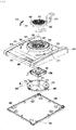
- FIG. 3 is an exploded perspective view of a sterilizing/drying/deodorizing apparatus according to the present invention
- FIG. 4 is an exploded perspective view of the sterilizing/drying/deodorizing apparatus according to the present invention, as seen from below
- FIG. 5 is an exploded perspective view of a principal part extracted from the sterilizing/drying/deodorizing apparatus according to the present invention
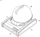
- FIG. 6 is a perspective view of the sterilizing/drying/deodorizing apparatus according to the present invention
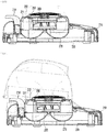
- FIG. 10 is a longitudinal-sectional view of the sterilizing/drying/deodorizing apparatus according to the present invention
- FIG. 11 is a longitudinal-sectional view illustrating the usage state of the sterilizing/drying/deodorizing apparatus according to the present invention.
- a case main body 210 of the sterilizing/drying/deodorizing apparatus is formed to have a rectangular structure in which a right portion is slightly low and a left portion is slightly high in FIGs. 3 and 4 . That is, since the sterilizing/drying/deodorizing apparatus is hung on the wall at an industrial site, the right portion of the case main body 210 corresponding to a lower part is configured to be slightly lower than the other portion of the case main body 210 so that a safety helmet is easily mounted on the case main body 210.
- a cylindrical installation hole part 211 which extends vertically is formed at the center of the upper portion of the case main body 210 to a designated height, and an air guide ring part 221 is formed at a predetermined interval from the inner circumferential surface of the installation hole part 211 so that an air vent 221 is provided between the installation hole part 211 and the air guide ring part 222.
- the air vent 221 communicates with the inside of the case main body 210, as shown in FIGs.
- a safety net 230 is formed on the upper portion of the inside of an opening of the air guide ring part 222
- a installation protrusion part 219 having a plurality of fastening holes 220 is formed on the upper portion of the inside of the air guide ring part 222, and one side of each of the fastening holes 220 has a larger area and the other side of each of the fastening holes 220 extending from the one side has a slightly smaller area, as shown in FIG. 3 .
- a safety helmet seated recess part 212 is formed in the upper portion of the case main body close to the installation hole part so that a safety band protruding from a hat, particularly, a safety helmet, may be stably mounted on the safety helmet seated recess part 212, as shown in FIG. 11 , and a hanger part 214, on which the safety helmet is stably hung, is installed at the center portion of the safety helmet seated recess part 212 and is fixedly inserted into a fitting hole (not shown) formed through the central portion of the safety helmet seated recess part 212 to be opened upwards.
- fixing holders 217 into which a front surface portion of the safety helmet forming a visor may be stably and fixedly inserted, are installed at both sides of the lower portion of the installation hole part 217, insertion grooves 215 having a curvature of a designated depth are formed in both sides of the lower portion of the installation hole part 211, screw parts are formed in the insertion grooves 215, and screw parts 218 extending downwards from the fixing holders 217 are engaged with the screw parts in the insertion grooves 215.
- a plurality of fastening bosses 211a, 211b and 211c arranged at designated intervals is formed on the open bottom surface of the case main body 210.
- a case bottom plate 240 is installed under the open bottom surface of the case main body 210, and a plurality of fastening bosses 241 corresponding to the fastening bosses 211a, 211b and 211c of the case main body 210 is formed on the case bottom plate 240 and is firmly coupled to the fastening bosses 211a, 211b and 211c by screws, as shown in FIGs. 4 and 9 .
- connection grooves 242 which are opened sideways to a designated depth, at both side portions of the case bottom plates 240 of two case main bodies 210 which are arranged close to each other, inserting one H-shaped connection holder 244 into the neighboring connection grooves 242 of the case main bodies 210, which are close to each other, and then coupling the connection holder 244 to the connection grooves 242 using screws.
- a female terminal part 243 to which power may be applied is formed at each of both sides of the case bottom plate 240 of each case main body 210, a male terminal part 710 connected to an external power supply 700 is connected to one female terminal part 243 of the case bottom plate 240, which is located at the outermost position, and power is supplied to other case bottom plates disposed close to the case bottom plate 240 connected to the external power supply 700 using a jump wire 720 having male terminal parts 721 provided at both ends thereof.
- the intake fan 260 is installed close to the safety net 230 installed on the bottom surface of the center of the case main body 210, and is screwed to the fastening bosses 211b of the case main body 210.
- an air induction part 270 corresponding to the installation hole part 211 protruding from the bottom surface of the center of the case main body 210 is installed, and the air induction part 270 has an air distribution protrusion 272 having a conical shape which protrudes upwards from the central portion of the air induction part 270, to uniformly distribute external air suctioned by the intake fan 260 without colliding therewith and simultaneously to raise the air along the inner circumferential surface of the air induction part 270 so as to exhaust the air to the air vent 221 between the installation hole part 211 and the air guide ring part 222.
- a filter case 250 is detachably installed on the upper surface of the safety net 230 of the case main body 210, an installation net 251 is formed on the upper surface of the filter case 250, a disc-shaped filter member 500 is installed under the bottom surface of the installation net 251, a net-shaped fixing frame body 253 is coupled to the bottom surface of the filter member 500 so as to stably fix the filter member 500 from below, a deodorizing ball accommodation cabinet 253a having a plurality of intake holes 253b is formed on the central portion of the bottom surface of the fixing frame body 253, deodorizing balls 600, which may remove unpleasant smells from air primarily passed through the filter member 500, completely fill the inside of the deodorizing ball accommodation cabinet 253a through an open upper surface thereof, and the open upper surface of the deodorizing ball accommodation cabinet 253a is closed by the filter member 500, as shown in FIG. 5 .
- fixing protrusions 255 are formed at the edge of the fixing frame body 253 and coupled to fixing holes 258 formed in the inner circumferential surface of the filter case 250, and thus, the fixing frame body 253 is not separated from the filter case 250 even when subjected to external shocks.
- L-shaped fastening parts 252 corresponding to the fastening holes 220 formed in the upper portion of the inside of the air guide ring part 222 are formed on the bottom surface of the fixing frame body 253, one side surface of a bent end of each of the fastening parts 252 is thinner than the other side surface of the bent end so that the filter case 250 may be very easily rotated in one lateral direction in the state in which the fastening parts 252 are inserted into the fastening holes 220, and the bent ends of the fastening parts 252 closely contact the bottom surface of the installation protrusion part 219 so as to stably fix the filter case 250.
- Ion generators 400 which may remove smells and various bacteria from inflowing air are respectively installed on both sides of the air induction part 270 within the filter case 250, as shown in FIG. 4 .
- a control member 300 having a plurality of operation buttons so as to control operation of the intake fan 260 and the ion generators 400 for a designated time is installed within the filter case 250, and the operation buttons of the control member 300 are exposed from the upper surface of the case main body 250.
- a sensor unit 800 such as an infrared proximity sensor, is installed within the case main body 250, and the sensor unit 800 is exposed upwards through a sensor hole 225 formed through the upper surface of the case main body 250, as shown in FIG. 3 , and may thus operate the control member 300 for a designated time when the safety helmet is mounted on the case main body 250.
- the sensor unit 800 may be installed at other positions, for example, at the safety helmet hanger part 240, and a switch unit which is operated by the weight of the safety helmet may be installed at the mounting part 240.
- the disc-shaped filter member 500 is installed under the bottom surface of the installation net 251 of the filter case 250 and simultaneously the net-shaped fixing frame body 253 is coupled to the bottom surface of the filter member 500 so as to stably fix the filter member 500 from below, the deodorizing balls 600, which may remove unpleasant smells from air primarily passed through the filter member 500, completely fill the inside of the deodorizing ball accommodation cabinet 253a, which is formed on the lower surface of the central portion of the fixing frame body 253, through the open upper surface thereof, and then, the open upper surface of the deodorizing ball accommodation cabinet 253a is closed by the filter member 500.
- the filter case 250 is coupled to the case main body 210, and in this case, the L-shaped fastening parts 252 formed on the bottom surface of the fixing frame body 253 are inserted into the fastening holes 220 formed in the upper portion of the inside of the air guide ring part 222 and then the filter case 250 is rotated in one lateral direction.
- the filter case 250 when the filter case 250 is rotated in one lateral direction, the bent ends of the fastening parts 252 closely contact the bottom surface of the installation protrusion part 219 and thus the filter case 250 may be stably fixed.
- the intake fan 260 is installed on the bottom surface of the center of the case main body 210, the air induction part 270 is installed so as to correspond to the installation hole part 211 protruding from bottom surface of the center of the case main body 210, and finally the case bottom plate 240 is coupled to the bottom surface of the case main body 210 using screws.
- case main bodies 210 are arranged such that the connection grooves 242 formed in both side portions of the case main bodies 240 are connected to each other, and then one H-shaped connection holder 244 is inserted into the connection grooves 242, which are connected, and is coupled to the connection grooves 242 using screws, thereby connecting the case main bodies 210, as shown in FIGs. 8 and 9 ./
- the male terminal part 710 connected to the external power supply 700 is connected to one female terminal part 243 of the case bottom plate 240, located at the outermost position among the female terminal parts 243 provided at both sides of the connected case bottom plates 240, and the male terminal parts 721 of the jump wire 720 are connected in series to the corresponding female terminal parts 243 of two connected case bottom plates 240, and thereby, power is applied to all of the connected case bottom plates 240.
- the safety helmet to remove contaminants therefrom is hung on the hanger part 214 of the case main body 250, or a visor of the safety helmet is inserted into the fixing holders 217 of the case main body 250, and thereby, the visor is in surface contact with the curved inner surfaces of the fixing holders 217 and thus separation of the safety helmet from the apparatus may be prevented.
- the sensor unit 800 installed within the case main body 250 senses the safety helmet and thus operates the control member 300, and in this case, the ion generators 400 within the case main body 250 are operated to prepare for sterilization and deodorization of the safety helmet, and simultaneously, the intake fan 260 is operated to suction contaminants into the case main body 210 from the safety helmet.
- Air having passed through the filter member 500 is suctioned into the deodorizing ball accommodation cabinet 253a formed at the central portion of the fixing frame body 253 installed under the bottom surface of the filter member 500, and is thus filtered so as to remove unpleasant smells through the deodorizing balls 600 accommodated in the deodorizing ball accommodation cabinet 253a, and the filtered air is suctioned into the air induction part 270 of the case main body 210 through the intake holes 253b formed through the deodorizing ball accommodation cabinet 253a.
- the air introduced into the air induction part 270 is uniformly distributed by the air distribution protrusion 272 protruding upwards from the central portion of the air induction part 270, and is simultaneously raised along the inner circumferential surface of the air induction part 270 having a curved surface, thereby being exhausted to the air vent 221 between the installation hole part 211 and the air guide ring part 222 and then being injected to the inner surface of the safety helmet.
Landscapes
- Health & Medical Sciences (AREA)
- Epidemiology (AREA)
- Life Sciences & Earth Sciences (AREA)
- Animal Behavior & Ethology (AREA)
- General Health & Medical Sciences (AREA)
- Public Health (AREA)
- Veterinary Medicine (AREA)
- Engineering & Computer Science (AREA)
- Mechanical Engineering (AREA)
- General Engineering & Computer Science (AREA)
- Disinfection, Sterilisation Or Deodorisation Of Air (AREA)
- Helmets And Other Head Coverings (AREA)
- Accessory Of Washing/Drying Machine, Commercial Washing/Drying Machine, Other Washing/Drying Machine (AREA)
- Apparatus For Disinfection Or Sterilisation (AREA)
Applications Claiming Priority (2)
| Application Number | Priority Date | Filing Date | Title |
|---|---|---|---|
| KR1020170099575A KR101965064B1 (ko) | 2017-08-07 | 2017-08-07 | 안전모를 포함한 모자의 살균/건조/탈취장치 |
| PCT/KR2018/008867 WO2019031777A1 (ko) | 2017-08-07 | 2018-08-03 | 안전모를 포함한 모자의 살균/건조/탈취장치 |
Publications (2)
| Publication Number | Publication Date |
|---|---|
| EP3666291A1 true EP3666291A1 (de) | 2020-06-17 |
| EP3666291A4 EP3666291A4 (de) | 2021-07-14 |
Family
ID=65271804
Family Applications (1)
| Application Number | Title | Priority Date | Filing Date |
|---|---|---|---|
| EP18844894.8A Withdrawn EP3666291A4 (de) | 2017-08-07 | 2018-08-03 | Vorrichtung zum sterilisieren/trocknen/deodorisieren von helmen, einschliesslich sicherheitshelmen |
Country Status (5)
| Country | Link |
|---|---|
| EP (1) | EP3666291A4 (de) |
| JP (1) | JP2020536704A (de) |
| KR (1) | KR101965064B1 (de) |
| CN (1) | CN111050810B (de) |
| WO (1) | WO2019031777A1 (de) |
Families Citing this family (8)
| Publication number | Priority date | Publication date | Assignee | Title |
|---|---|---|---|---|
| WO2021076063A1 (en) * | 2019-10-18 | 2021-04-22 | Inroon Apipu | Helmet dehumidifier-disinfection device |
| KR20210056534A (ko) | 2019-11-11 | 2021-05-20 | 김동욱 | 헬멧 건조대 |
| KR102428900B1 (ko) | 2020-09-29 | 2022-08-02 | 김영수 | 오토바이크용 헬멧 살균소독 장치 |
| KR102675783B1 (ko) * | 2021-06-09 | 2024-06-18 | 이성현 | 헬멧 스타일러 장치 |
| CN113401472A (zh) * | 2021-07-08 | 2021-09-17 | 玛狮智能出行股份公司 | 一种车载智能头盔盒 |
| KR102693328B1 (ko) | 2022-06-27 | 2024-08-07 | 노진문 | 헬멧 자동 관리 장치 |
| KR200497040Y1 (ko) * | 2022-12-06 | 2023-07-06 | 이명진 | 방탄헬멧용 다목적 살균기 |
| US12453794B1 (en) | 2024-05-30 | 2025-10-28 | Innovative Creations, LLC | Helmet mount with accessories |
Family Cites Families (16)
| Publication number | Priority date | Publication date | Assignee | Title |
|---|---|---|---|---|
| JPH10192798A (ja) * | 1997-01-14 | 1998-07-28 | Shiiraizu Corp:Kk | ヘルメットの洗浄装置 |
| JP3093354U (ja) * | 2002-10-10 | 2003-05-09 | 純一 井上 | ヘルメット乾燥機 |
| JP3917105B2 (ja) * | 2003-05-02 | 2007-05-23 | 株式会社ココロ | カツラなどの脱臭・除菌装置 |
| KR100608128B1 (ko) * | 2004-07-30 | 2006-08-08 | 삼성전자주식회사 | 공기조화기 |
| CN200973845Y (zh) * | 2006-11-08 | 2007-11-14 | 李文王 | 安全帽紫外线臭氧杀菌清净机 |
| KR20100074951A (ko) * | 2008-12-24 | 2010-07-02 | 김용호 | 살균작용을 하는 모자 보관함 |
| KR101064464B1 (ko) * | 2009-11-19 | 2011-09-15 | 우상헌 | 휴대용 살균 칫솔함 |
| JP4927199B2 (ja) * | 2010-06-09 | 2012-05-09 | シャープ株式会社 | イオン発生機 |
| KR101475876B1 (ko) | 2013-02-26 | 2014-12-23 | 변효섭 | 안전모 세척기 |
| WO2014169359A1 (pt) * | 2013-04-18 | 2014-10-23 | Tacchini Ramos Victor | Dispositivo higienizador |
| KR101550261B1 (ko) * | 2013-05-06 | 2015-09-10 | 아트먼 주식회사 | 공기정화 기능을 갖는 주방용 후드 |
| CN104949212B (zh) * | 2014-03-28 | 2017-11-14 | Lg电子株式会社 | 空气净化器 |
| KR101494677B1 (ko) * | 2014-06-03 | 2015-02-23 | 길종진 | 수용 공간을 구비하는 공기정화장치 |
| KR101663371B1 (ko) * | 2014-09-03 | 2016-10-06 | 전북대학교산학협력단 | TiO2의 광촉매 반응을 이용한 모자 살균기 |
| KR20160078166A (ko) * | 2014-12-24 | 2016-07-04 | 이종란 | 자외선 살균램프가 구비된 모자 거치 장치 |
| KR20160109597A (ko) * | 2015-03-12 | 2016-09-21 | 주식회사 건파워 | 자외선을 이용한 헬멧의 살균 소독 장치 |
-
2017
- 2017-08-07 KR KR1020170099575A patent/KR101965064B1/ko active Active
-
2018
- 2018-08-03 EP EP18844894.8A patent/EP3666291A4/de not_active Withdrawn
- 2018-08-03 WO PCT/KR2018/008867 patent/WO2019031777A1/ko not_active Ceased
- 2018-08-03 CN CN201880051303.2A patent/CN111050810B/zh not_active Expired - Fee Related
- 2018-08-03 JP JP2020529081A patent/JP2020536704A/ja active Pending
Also Published As
| Publication number | Publication date |
|---|---|
| EP3666291A4 (de) | 2021-07-14 |
| WO2019031777A1 (ko) | 2019-02-14 |
| KR20190016163A (ko) | 2019-02-18 |
| JP2020536704A (ja) | 2020-12-17 |
| CN111050810A (zh) | 2020-04-21 |
| KR101965064B1 (ko) | 2019-04-03 |
| CN111050810B (zh) | 2021-05-25 |
Similar Documents
| Publication | Publication Date | Title |
|---|---|---|
| EP3666291A1 (de) | Vorrichtung zum sterilisieren/trocknen/deodorisieren von helmen, einschliesslich sicherheitshelmen | |
| CN114617491B (zh) | 清洁系统的基座、清洁系统及滚刷清洁方法 | |
| KR102771776B1 (ko) | 드라이어 거치대 | |
| JP6899847B2 (ja) | 空気処理装置のための加湿モジュール | |
| KR100934316B1 (ko) | 가습 및 공기청정 기능을 가지는 가정용 제습장치 | |
| EP3626108B1 (de) | Trocknerständer | |
| CN106945710B (zh) | 用于婴儿车罩的通风装置 | |
| KR102882068B1 (ko) | 펫 드라이룸 | |
| KR20220043273A (ko) | 오토바이크용 헬멧 살균소독 장치 | |
| KR20150032989A (ko) | 온풍 기능을 구비하는 공기청정기 | |
| CN212369325U (zh) | 消毒、干燥、除异味、充电的装置 | |
| CN212538089U (zh) | 空气清净杀菌除湿机 | |
| CN215892689U (zh) | 一种杀菌空气净化器 | |
| KR101568978B1 (ko) | 높이 조절이 가능한 안전보호구용 살균 건조 보관함 | |
| CN112323338B (zh) | 衣物处理设备 | |
| CN209932593U (zh) | 一种地面吹风装置及消毒柜 | |
| CN213429042U (zh) | 衣柜 | |
| CN209084955U (zh) | 一种衣物护理机的空气净化装置 | |
| CN215976484U (zh) | 衣物处理装置 | |
| KR20220166142A (ko) | 헬멧 스타일러 장치 | |
| KR200420456Y1 (ko) | 자외선 살균드라이기 | |
| KR200480333Y1 (ko) | 청정온풍기 | |
| CN223935438U (zh) | 一种纺织品防霉变的保护装置 | |
| CN216047990U (zh) | 一种灭菌机构可拆卸的智能浴霸结构 | |
| CN221254994U (zh) | 气流转换装置及护理设备 |
Legal Events
| Date | Code | Title | Description |
|---|---|---|---|
| STAA | Information on the status of an ep patent application or granted ep patent |
Free format text: STATUS: THE INTERNATIONAL PUBLICATION HAS BEEN MADE |
|
| PUAI | Public reference made under article 153(3) epc to a published international application that has entered the european phase |
Free format text: ORIGINAL CODE: 0009012 |
|
| STAA | Information on the status of an ep patent application or granted ep patent |
Free format text: STATUS: REQUEST FOR EXAMINATION WAS MADE |
|
| 17P | Request for examination filed |
Effective date: 20200203 |
|
| AK | Designated contracting states |
Kind code of ref document: A1 Designated state(s): AL AT BE BG CH CY CZ DE DK EE ES FI FR GB GR HR HU IE IS IT LI LT LU LV MC MK MT NL NO PL PT RO RS SE SI SK SM TR |
|
| AX | Request for extension of the european patent |
Extension state: BA ME |
|
| DAV | Request for validation of the european patent (deleted) | ||
| DAX | Request for extension of the european patent (deleted) | ||
| A4 | Supplementary search report drawn up and despatched |
Effective date: 20210611 |
|
| RIC1 | Information provided on ipc code assigned before grant |
Ipc: A61L 2/06 20060101AFI20210607BHEP Ipc: A61L 2/26 20060101ALI20210607BHEP Ipc: A61L 9/22 20060101ALI20210607BHEP Ipc: F26B 21/02 20060101ALI20210607BHEP |
|
| STAA | Information on the status of an ep patent application or granted ep patent |
Free format text: STATUS: THE APPLICATION IS DEEMED TO BE WITHDRAWN |
|
| 18D | Application deemed to be withdrawn |
Effective date: 20220111 |