EP3666244B1 - Translationale drehmaschine - Google Patents
Translationale drehmaschine Download PDFInfo
- Publication number
- EP3666244B1 EP3666244B1 EP19214700.7A EP19214700A EP3666244B1 EP 3666244 B1 EP3666244 B1 EP 3666244B1 EP 19214700 A EP19214700 A EP 19214700A EP 3666244 B1 EP3666244 B1 EP 3666244B1
- Authority
- EP
- European Patent Office
- Prior art keywords
- pulleys
- pulley
- pair
- machine
- axis
- Prior art date
- Legal status (The legal status is an assumption and is not a legal conclusion. Google has not performed a legal analysis and makes no representation as to the accuracy of the status listed.)
- Active
Links
Images


Classifications
-
- A—HUMAN NECESSITIES
- A61—MEDICAL OR VETERINARY SCIENCE; HYGIENE
- A61H—PHYSICAL THERAPY APPARATUS, e.g. DEVICES FOR LOCATING OR STIMULATING REFLEX POINTS IN THE BODY; ARTIFICIAL RESPIRATION; MASSAGE; BATHING DEVICES FOR SPECIAL THERAPEUTIC OR HYGIENIC PURPOSES OR SPECIFIC PARTS OF THE BODY
- A61H1/00—Apparatus for passive exercising; Vibrating apparatus; Chiropractic devices, e.g. body impacting devices, external devices for briefly extending or aligning unbroken bones
- A61H1/02—Stretching or bending or torsioning apparatus for exercising
- A61H1/0214—Stretching or bending or torsioning apparatus for exercising by rotating cycling movement
-
- A—HUMAN NECESSITIES
- A61—MEDICAL OR VETERINARY SCIENCE; HYGIENE
- A61H—PHYSICAL THERAPY APPARATUS, e.g. DEVICES FOR LOCATING OR STIMULATING REFLEX POINTS IN THE BODY; ARTIFICIAL RESPIRATION; MASSAGE; BATHING DEVICES FOR SPECIAL THERAPEUTIC OR HYGIENIC PURPOSES OR SPECIFIC PARTS OF THE BODY
- A61H1/00—Apparatus for passive exercising; Vibrating apparatus; Chiropractic devices, e.g. body impacting devices, external devices for briefly extending or aligning unbroken bones
- A61H1/02—Stretching or bending or torsioning apparatus for exercising
- A61H1/0237—Stretching or bending or torsioning apparatus for exercising for the lower limbs
-
- A—HUMAN NECESSITIES
- A61—MEDICAL OR VETERINARY SCIENCE; HYGIENE
- A61H—PHYSICAL THERAPY APPARATUS, e.g. DEVICES FOR LOCATING OR STIMULATING REFLEX POINTS IN THE BODY; ARTIFICIAL RESPIRATION; MASSAGE; BATHING DEVICES FOR SPECIAL THERAPEUTIC OR HYGIENIC PURPOSES OR SPECIFIC PARTS OF THE BODY
- A61H1/00—Apparatus for passive exercising; Vibrating apparatus; Chiropractic devices, e.g. body impacting devices, external devices for briefly extending or aligning unbroken bones
- A61H1/02—Stretching or bending or torsioning apparatus for exercising
- A61H1/0274—Stretching or bending or torsioning apparatus for exercising for the upper limbs
-
- A—HUMAN NECESSITIES
- A63—SPORTS; GAMES; AMUSEMENTS
- A63B—APPARATUS FOR PHYSICAL TRAINING, GYMNASTICS, SWIMMING, CLIMBING, OR FENCING; BALL GAMES; TRAINING EQUIPMENT
- A63B21/00—Exercising apparatus for developing or strengthening the muscles or joints of the body by working against a counterforce, with or without measuring devices
- A63B21/00178—Exercising apparatus for developing or strengthening the muscles or joints of the body by working against a counterforce, with or without measuring devices for active exercising, the apparatus being also usable for passive exercising
-
- A—HUMAN NECESSITIES
- A63—SPORTS; GAMES; AMUSEMENTS
- A63B—APPARATUS FOR PHYSICAL TRAINING, GYMNASTICS, SWIMMING, CLIMBING, OR FENCING; BALL GAMES; TRAINING EQUIPMENT
- A63B22/00—Exercising apparatus specially adapted for conditioning the cardio-vascular system, for training agility or co-ordination of movements
- A63B22/06—Exercising apparatus specially adapted for conditioning the cardio-vascular system, for training agility or co-ordination of movements with support elements performing a rotating cycling movement, i.e. a closed path movement
- A63B22/0605—Exercising apparatus specially adapted for conditioning the cardio-vascular system, for training agility or co-ordination of movements with support elements performing a rotating cycling movement, i.e. a closed path movement performing a circular movement, e.g. ergometers
-
- A—HUMAN NECESSITIES
- A63—SPORTS; GAMES; AMUSEMENTS
- A63B—APPARATUS FOR PHYSICAL TRAINING, GYMNASTICS, SWIMMING, CLIMBING, OR FENCING; BALL GAMES; TRAINING EQUIPMENT
- A63B22/00—Exercising apparatus specially adapted for conditioning the cardio-vascular system, for training agility or co-ordination of movements
- A63B22/06—Exercising apparatus specially adapted for conditioning the cardio-vascular system, for training agility or co-ordination of movements with support elements performing a rotating cycling movement, i.e. a closed path movement
- A63B22/0664—Exercising apparatus specially adapted for conditioning the cardio-vascular system, for training agility or co-ordination of movements with support elements performing a rotating cycling movement, i.e. a closed path movement performing an elliptic movement
-
- F—MECHANICAL ENGINEERING; LIGHTING; HEATING; WEAPONS; BLASTING
- F16—ENGINEERING ELEMENTS AND UNITS; GENERAL MEASURES FOR PRODUCING AND MAINTAINING EFFECTIVE FUNCTIONING OF MACHINES OR INSTALLATIONS; THERMAL INSULATION IN GENERAL
- F16H—GEARING
- F16H19/00—Gearings comprising essentially only toothed gears or friction members and not capable of conveying indefinitely-continuing rotary motion
- F16H19/02—Gearings comprising essentially only toothed gears or friction members and not capable of conveying indefinitely-continuing rotary motion for interconverting rotary or oscillating motion and reciprocating motion
- F16H19/06—Gearings comprising essentially only toothed gears or friction members and not capable of conveying indefinitely-continuing rotary motion for interconverting rotary or oscillating motion and reciprocating motion comprising flexible members, e.g. an endless flexible member
-
- A—HUMAN NECESSITIES
- A61—MEDICAL OR VETERINARY SCIENCE; HYGIENE
- A61H—PHYSICAL THERAPY APPARATUS, e.g. DEVICES FOR LOCATING OR STIMULATING REFLEX POINTS IN THE BODY; ARTIFICIAL RESPIRATION; MASSAGE; BATHING DEVICES FOR SPECIAL THERAPEUTIC OR HYGIENIC PURPOSES OR SPECIFIC PARTS OF THE BODY
- A61H2201/00—Characteristics of apparatus not provided for in the preceding codes
- A61H2201/12—Driving means
- A61H2201/1207—Driving means with electric or magnetic drive
- A61H2201/1215—Rotary drive
-
- A—HUMAN NECESSITIES
- A61—MEDICAL OR VETERINARY SCIENCE; HYGIENE
- A61H—PHYSICAL THERAPY APPARATUS, e.g. DEVICES FOR LOCATING OR STIMULATING REFLEX POINTS IN THE BODY; ARTIFICIAL RESPIRATION; MASSAGE; BATHING DEVICES FOR SPECIAL THERAPEUTIC OR HYGIENIC PURPOSES OR SPECIFIC PARTS OF THE BODY
- A61H2201/00—Characteristics of apparatus not provided for in the preceding codes
- A61H2201/12—Driving means
- A61H2201/1253—Driving means driven by a human being, e.g. hand driven
- A61H2201/1261—Driving means driven by a human being, e.g. hand driven combined with active exercising of the patient
-
- A—HUMAN NECESSITIES
- A61—MEDICAL OR VETERINARY SCIENCE; HYGIENE
- A61H—PHYSICAL THERAPY APPARATUS, e.g. DEVICES FOR LOCATING OR STIMULATING REFLEX POINTS IN THE BODY; ARTIFICIAL RESPIRATION; MASSAGE; BATHING DEVICES FOR SPECIAL THERAPEUTIC OR HYGIENIC PURPOSES OR SPECIFIC PARTS OF THE BODY
- A61H2201/00—Characteristics of apparatus not provided for in the preceding codes
- A61H2201/14—Special force transmission means, i.e. between the driving means and the interface with the user
- A61H2201/1436—Special crank assembly
-
- A—HUMAN NECESSITIES
- A61—MEDICAL OR VETERINARY SCIENCE; HYGIENE
- A61H—PHYSICAL THERAPY APPARATUS, e.g. DEVICES FOR LOCATING OR STIMULATING REFLEX POINTS IN THE BODY; ARTIFICIAL RESPIRATION; MASSAGE; BATHING DEVICES FOR SPECIAL THERAPEUTIC OR HYGIENIC PURPOSES OR SPECIFIC PARTS OF THE BODY
- A61H2201/00—Characteristics of apparatus not provided for in the preceding codes
- A61H2201/14—Special force transmission means, i.e. between the driving means and the interface with the user
- A61H2201/1463—Special speed variation means, i.e. speed reducer
-
- A—HUMAN NECESSITIES
- A61—MEDICAL OR VETERINARY SCIENCE; HYGIENE
- A61H—PHYSICAL THERAPY APPARATUS, e.g. DEVICES FOR LOCATING OR STIMULATING REFLEX POINTS IN THE BODY; ARTIFICIAL RESPIRATION; MASSAGE; BATHING DEVICES FOR SPECIAL THERAPEUTIC OR HYGIENIC PURPOSES OR SPECIFIC PARTS OF THE BODY
- A61H2201/00—Characteristics of apparatus not provided for in the preceding codes
- A61H2201/14—Special force transmission means, i.e. between the driving means and the interface with the user
- A61H2201/1481—Special movement conversion means
- A61H2201/149—Special movement conversion means rotation-linear or vice versa
-
- A—HUMAN NECESSITIES
- A61—MEDICAL OR VETERINARY SCIENCE; HYGIENE
- A61H—PHYSICAL THERAPY APPARATUS, e.g. DEVICES FOR LOCATING OR STIMULATING REFLEX POINTS IN THE BODY; ARTIFICIAL RESPIRATION; MASSAGE; BATHING DEVICES FOR SPECIAL THERAPEUTIC OR HYGIENIC PURPOSES OR SPECIFIC PARTS OF THE BODY
- A61H2201/00—Characteristics of apparatus not provided for in the preceding codes
- A61H2201/16—Physical interface with patient
- A61H2201/1602—Physical interface with patient kind of interface, e.g. head rest, knee support or lumbar support
- A61H2201/1635—Hand or arm, e.g. handle
-
- A—HUMAN NECESSITIES
- A61—MEDICAL OR VETERINARY SCIENCE; HYGIENE
- A61H—PHYSICAL THERAPY APPARATUS, e.g. DEVICES FOR LOCATING OR STIMULATING REFLEX POINTS IN THE BODY; ARTIFICIAL RESPIRATION; MASSAGE; BATHING DEVICES FOR SPECIAL THERAPEUTIC OR HYGIENIC PURPOSES OR SPECIFIC PARTS OF THE BODY
- A61H2201/00—Characteristics of apparatus not provided for in the preceding codes
- A61H2201/16—Physical interface with patient
- A61H2201/1602—Physical interface with patient kind of interface, e.g. head rest, knee support or lumbar support
- A61H2201/164—Feet or leg, e.g. pedal
-
- A—HUMAN NECESSITIES
- A61—MEDICAL OR VETERINARY SCIENCE; HYGIENE
- A61H—PHYSICAL THERAPY APPARATUS, e.g. DEVICES FOR LOCATING OR STIMULATING REFLEX POINTS IN THE BODY; ARTIFICIAL RESPIRATION; MASSAGE; BATHING DEVICES FOR SPECIAL THERAPEUTIC OR HYGIENIC PURPOSES OR SPECIFIC PARTS OF THE BODY
- A61H2201/00—Characteristics of apparatus not provided for in the preceding codes
- A61H2201/16—Physical interface with patient
- A61H2201/1657—Movement of interface, i.e. force application means
- A61H2201/1664—Movement of interface, i.e. force application means linear
-
- A—HUMAN NECESSITIES
- A61—MEDICAL OR VETERINARY SCIENCE; HYGIENE
- A61H—PHYSICAL THERAPY APPARATUS, e.g. DEVICES FOR LOCATING OR STIMULATING REFLEX POINTS IN THE BODY; ARTIFICIAL RESPIRATION; MASSAGE; BATHING DEVICES FOR SPECIAL THERAPEUTIC OR HYGIENIC PURPOSES OR SPECIFIC PARTS OF THE BODY
- A61H2201/00—Characteristics of apparatus not provided for in the preceding codes
- A61H2201/16—Physical interface with patient
- A61H2201/1657—Movement of interface, i.e. force application means
- A61H2201/1671—Movement of interface, i.e. force application means rotational
-
- A—HUMAN NECESSITIES
- A61—MEDICAL OR VETERINARY SCIENCE; HYGIENE
- A61H—PHYSICAL THERAPY APPARATUS, e.g. DEVICES FOR LOCATING OR STIMULATING REFLEX POINTS IN THE BODY; ARTIFICIAL RESPIRATION; MASSAGE; BATHING DEVICES FOR SPECIAL THERAPEUTIC OR HYGIENIC PURPOSES OR SPECIFIC PARTS OF THE BODY
- A61H2205/00—Devices for specific parts of the body
- A61H2205/06—Arms
-
- F—MECHANICAL ENGINEERING; LIGHTING; HEATING; WEAPONS; BLASTING
- F16—ENGINEERING ELEMENTS AND UNITS; GENERAL MEASURES FOR PRODUCING AND MAINTAINING EFFECTIVE FUNCTIONING OF MACHINES OR INSTALLATIONS; THERMAL INSULATION IN GENERAL
- F16H—GEARING
- F16H19/00—Gearings comprising essentially only toothed gears or friction members and not capable of conveying indefinitely-continuing rotary motion
- F16H19/02—Gearings comprising essentially only toothed gears or friction members and not capable of conveying indefinitely-continuing rotary motion for interconverting rotary or oscillating motion and reciprocating motion
- F16H19/06—Gearings comprising essentially only toothed gears or friction members and not capable of conveying indefinitely-continuing rotary motion for interconverting rotary or oscillating motion and reciprocating motion comprising flexible members, e.g. an endless flexible member
- F16H2019/0681—Gearings comprising essentially only toothed gears or friction members and not capable of conveying indefinitely-continuing rotary motion for interconverting rotary or oscillating motion and reciprocating motion comprising flexible members, e.g. an endless flexible member the flexible member forming a closed loop
- F16H2019/0686—Gearings comprising essentially only toothed gears or friction members and not capable of conveying indefinitely-continuing rotary motion for interconverting rotary or oscillating motion and reciprocating motion comprising flexible members, e.g. an endless flexible member the flexible member forming a closed loop the flexible member being directly driven by a pulley or chain wheel
Definitions
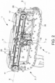
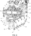
- the frame 2 comprises a support structure 5 for the translational-rotary members 3, which develops along a longitudinal axis X, and two columns 6, 6' which extend perpendicularly to the axis X, as shown in figure 1 .
- the translational-rotary members 3 comprise:
- the second return pulley 18 is operatively connected to the first toothed wheel 17 by means of a second toothed wheel 19, so that the force transmitted by the second transmission member 21 acts on the upper section of the first toothed wheel 17 ( figure 1-10 ).
- the force transmitted by the first transmission member 20 acts on the lower section of the first return pulley 16 ( figure 1-10 ).
- Shaped seats 32, 32' adapted to insert and connect various types of tools to the machine 1 are formed at the ends of the upper shaft 14.
- Figure 10 shows the application of a pair of handles 33, 33' connected to the upper shaft 14 by means of relative cranks 34, 34'. This application allows the user to rotate the handles 33, 33' both actively and passively.
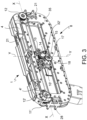
- a toothing 25 is formed on the lower shaft 15, at the centerline of the lower shaft 15.
- a toothed reduction wheel 26 is integrally keyed onto the upper shaft 14, at the centerline of the upper shaft 14, so as to mesh with the toothing 25 on the lower shaft 15 ( figure 4 ).
- the toothing 25 and the toothed reduction wheel 26 have different diameters from each other so as to form a motion reduction system ( figure 9 ).
- a respective pulley 11', 12 of each of said first 11, 11' and second 12, 12' pairs of pulleys is operatively connected to the respective motor means 4, 4' by means of gear motors.
- gear motors For example, a helical screw gear motor system, which will be described in greater detail below, may be advantageously used.
- the pulleys 11', 12' connected to the motor means 4, 4' are arranged symmetrically on the support structure 5, i.e. if pulley 11', directly connected to the respective motor means 4', is arranged at one end of the support structure 5 (and therefore of a column 6) in the first pair of pulleys, pulley 12, arranged on the other end of the support structure 5 (and therefore on the column 6') will be connected to the respective motor means 4' in the second pair of pulleys, or vice versa.
- the pulley 11' of the first pair of pulleys is connected, e.g. by means of a worm screw-helical cylindrical wheel coupling to the first motor means 4, while the pulley 12 of the second pair of pulleys is connected to second motor means 4'.
- the pulley 11' of the first pair of pulleys is connected to the first motor means 4', while the pulley 12' of the second pair of pulleys is connected to the second motor means 4'.
- the driving pulley 11' and the idler pulley 12' are keyed onto the same shaft, and the driving pulley 12 and the idler pulley 11 are keyed onto a further same shaft.
- the idler pulleys 11, 12' are keyed onto respective shafts by means of bearings so as to release said idler pulleys 11, 12' from the rotation of the driving pulleys 11', 12 which are instead integrally keyed onto the respective shafts.
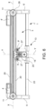
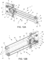
- Figures 7 and 8 show a detail of the system for transmitting motion from the motor means 4' to the pulley 11' of the first pair of pulleys, but a similar transmission system is also used for the pulley 12 of the second pair of pulleys.
- the pulley 11' is integrally mounted onto a first drive shaft 28', while the idler pulley 12' is mounted onto the first drive shaft 28' by means of bearings 31, so as to release the rotation of the idler pulley 12' from the rotation of the first drive shaft 28'.
- a first helical wheel 29 is keyed integrally to the first drive shaft 28, preferably at the centerline of the first drive shaft 28 ( figure 4 ).
- the first helical wheel 29 meshes with a first worm screw 30 which receives the motion from the motor means 4'.
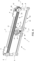
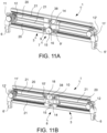
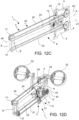
- the carriage 13 is slidable on a track 22 placed on a vertical plane and along the axis X.
- the track 22 comprises a lower rail 23 and an upper rail 24.
- the lower track 23 has a tubular shape
- the upper track 24 has a rectangular section, but nothing prevents reversing them or using sections of different shapes.
- the carriage 13 is therefore equipped with a first sliding seat for the lower track 23 and a second sliding seat for the upper track 24.
- the first sliding seat has, in turn, tubular shape with positive coupling with the lower track 23.
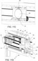
- the first and second pair of tension pulleys 9, 9' and 10, 10' are mounted on the carriage 13.
- the tension pulleys 9, 9' and 10, 10' are not motorized.
- the pulleys 9, 10 and the pulleys 9', 10' are keyed onto the ends of the respective shafts 27, 27'.
- the shafts 27, 27' cross the carriage 13 in a transversal direction to the plane of axes X-Y.
- the toothed reduction wheel 26 has a greater diameter than the toothing 25 so as to reduce the rotation speed of the upper shaft 14 with respect to the rotation speed of the lower shaft 15.
- the upper 14 and lower 15 shafts are connected by flexible transmission means, such as a chain or belt.
- the first 20 and second 21 transmission members consist of a double-toothed drive belt, a chain, a flexible drive or the like.
- the first transmission member 20 winds in the order:
- the lower shaft 15 receives the motion from the first return pulley 16 on the front side 7, the force transmitted by the transmission member 20 acting on the lower section of the return pulley 16.
- the lower shaft 15 receives the motion on the rear side 8 from the second toothed wheel 19, which is integral with the second return pulley 18, the force transmitted by the transmission member 21 acting on the upper section of the first toothed wheel 17.
- the user may be subject to passive physical activity, particularly indicated in the case of rehabilitative therapies.
- the motor means can also be operated so as to rotate the cranks 34, 34' with reciprocating tilting movement of the upper shaft 14, combined with a translation of the carriage 13 (according to the laws of motion described above), so as to exercise the limb (s) of a user.
- This type of exercise is particularly suited for rehabilitation therapies, mainly orthopedic.
- the machine 1 may comprise a supporting scaffolding 35.
- the translational-rotary members 3 comprise a second upper shaft 38 passing through the carriage 13, vertically aligned with the lower shaft 15 and with the upper shaft 14, and arranged above the lower shaft 15 and the upper shaft 14.
- the second return pulley 18 is integrally keyed onto the second upper shaft 38 on the rear side 8 of the machine 1.
- a second toothing 39 is formed on the second upper shaft 38, at the centerline of the upper shaft 38, so as to mesh with the reduction gear 26 keyed onto the upper shaft 14.
- the reduction toothed wheel 26 simultaneously meshes in lower section thereof with the toothing 25, and in its upper section thereof with the second toothing 39.
- the first transmission member 20, arranged on the front side 7 of machine 1, operationally connects the motor means 4, 4' to the first idler pulley 16, while the second transmission member 21, arranged on the rear side 8 of machine 1, operationally connects the motor means 4, 4' to the second idler pulley 18.
- the first idler pulley 16, the reduction toothed wheel 26 and the second idler pulley 18 are operationally connected to one another, so that the force transmitted by the first idler pulley 20 acts on the lower section of the first idler pulley 16, and the force transmitted by the second idler pulley 21 acts on the upper section of the second idler pulley 18.
- the lower shaft 15 receives the motion from the first return pulley 16 on the front side 7, the force transmitted by the transmission member 20 acting on the lower section of the return pulley 16.
- the translational-rotary members 3 comprises a middle shaft 42 passing through the carriage 13.
- the first idler pulley 16 and the second idler pulley 18 are integrally keyed to the middle shaft 42, on the front side 7 and on the rear side 8 of the machine 1, respectively.
- the force transmitted by the first transmission member (20) acts on the lower section of the first return pulley (16) and the force transmitted by the second transmission member (21) acts on the upper section of the second return pulley (18).
- the upper track 24 defines an upper axis 40 parallel to axis X
- the lower track 23 defines a lower axis 41 parallel to axis X
- the first pair of pulleys 11, 11' is arranged on the front side 7 of the machine 1, along the upper axis 24, while the second pair of pulleys 12, 12' is arranged on the rear side 8 of the machine 1, along the lower axis 23.
- motor 4' is connected to driving pulley 12', while pulley 12' is idle, and motor 4' is connected to driving pulley 11, while pulley 11' is idle.
- the central shaft 42 receives the motion from the first return pulley 16 on the front side 7, the force transmitted by the transmission member 20 acting on the lower section of the return pulley 16.
- the central shaft 42 receives the motion from the second return pulley 18 on the front side 8, the force transmitted by the transmission member 21 acting on the upper section of the second return pulley 18.
Landscapes
- Health & Medical Sciences (AREA)
- Physical Education & Sports Medicine (AREA)
- General Health & Medical Sciences (AREA)
- Life Sciences & Earth Sciences (AREA)
- Epidemiology (AREA)
- Pain & Pain Management (AREA)
- Rehabilitation Therapy (AREA)
- Animal Behavior & Ethology (AREA)
- Public Health (AREA)
- Veterinary Medicine (AREA)
- Cardiology (AREA)
- Vascular Medicine (AREA)
- Biophysics (AREA)
- Orthopedic Medicine & Surgery (AREA)
- Engineering & Computer Science (AREA)
- General Engineering & Computer Science (AREA)
- Mechanical Engineering (AREA)
- Devices For Conveying Motion By Means Of Endless Flexible Members (AREA)
- Rehabilitation Tools (AREA)
- Forklifts And Lifting Vehicles (AREA)
- Supercharger (AREA)
- Pulleys (AREA)
Claims (11)
- Maschine zum physischen Trainieren der Gliedmaßen, umfassend eine translatorisch-rotatorische Maschine (1), welche Motoreinrichtungen (4, 4') und translatorisch-rotatorische Elemente (3) umfasst, wobei die translatorisch-rotatorischen Elemente (3) umfassen:- einen bewegbaren Schlitten (13);- eine untere Welle (15), welche den Schlitten (13) durchdringt;- eine erste Rücklaufrolle (16), welche an der unteren Welle (15) an der vorderen Seite (7) der Maschine (1) integral verkeilt ist;- ein erstes Zahnrad (17), welches an der unteren Welle (15) an der hinteren Seite (8) der Maschine (1) integral verkeilt ist;- eine obere Welle (14), welche den Schlitten (13) durchdringt, wobei die obere Welle (14) mit der unteren Welle (15) vertikal ausgerichtet ist;- eine zweite Rücklaufrolle (18), welche an der oberen Welle (14) an der hinteren Seite der Maschine (1) frei angebracht ist;- ein erstes Übertragungselement (20), welches an einer vorderen Seite (7) der Maschine (1) angeordnet ist, wobei das erste Übertragungselement (20) dazu eingerichtet ist, die Motoreinrichtungen (4, 4') mit der ersten Rücklaufrolle (16) betriebsfähig zu verbinden;- ein zweites Übertragungselement (21), welches an einer hinteren Seite (8) der Maschine (1) angeordnet ist, wobei das zweite Übertragungselement (21) dazu eingerichtet ist, die Motoreinrichtungen (4, 4') mit der zweiten Rücklaufrolle (18) betriebsfähig zu verbinden;wobei die zweite Rücklaufrolle (18) mit dem ersten Zahnrad (17) mit Hilfe eines zweiten Zahnrads (19) betriebsfähig verbunden ist, sodass die Kraft, welche durch das zweite Übertragungselement (21) übertragen ist, auf den oberen Abschnitt des ersten Zahnrads (17) wirkt,und wobei die Kraft, welche durch das erste Übertragungselement (20) übertragen ist, auf den unteren Abschnitt der ersten Rücklaufrolle (16) wirkt,wobei geformte Sitze (32), (32'), welche dazu eingerichtet sind, verschiedene Typen von Geräten in die Maschine (1) aufzunehmen und mit dieser zu verbinden, an den Enden der oberen Welle (14) gebildet sind,und wobei ein Paar von Griffen (33), (33'), oder Zubehörteile eines anderen Typs, mit der oberen Welle (14) mit Hilfe von entsprechenden Hebeln (34, 34') verbunden sind,wobei eine Zahnung (25) an der unteren Welle (15) gebildet ist, an der Mittellinie der unteren Welle (15), und wobei ein Untersetzungszahnrad (26) an der oberen Welle (14) integral verkeilt ist, an der Mittellinie der oberen Welle (14), um mit der Zahnung (25) an der unteren Welle (15) zu kämmen,und wobei die Zahnung (25) und das Untersetzungszahnrad (26) voneinander verschiedene Durchmesser aufweisen, um ein Bewegungsuntersetzungssystem zu bilden.
- Maschine nach Anspruch 1, umfassend einen Rahmen (2), an welchem die translatorisch-rotatorischen Elemente (3) angebracht sind, wobei der Rahmen (2) eine Halterungsstruktur (5) für die translatorisch-rotatorischen Elemente (3) umfasst, welche sich entlang einer Longitudinalachse X erstreckt, und:- ein erstes Paar von Umlenkrollen (11, 11') an der vorderen Seite (7) der Maschine (1) angeordnet ist, an den Enden der Halterungsstruktur (5), wobei die Umlenkrollen (11, 11') des ersten Paars entlang einer Achse ausgerichtet sind, welche im Wesentlichen Parallel zu der Achse X ist;- ein zweites Paar von Umlenkrollen (12, 12') an der hinteren Seite (8) der Maschine (1) angeordnet ist, an den Enden der Halterungsstruktur (5), wobei die Umlenkrollen (12, 12') des zweiten Paars entlang einer Achse ausgerichtet sind, welche im Wesentlichen Parallel zu der Achse X ist;- der Schlitten (13) angeordnet ist, um sich entlang der Achse X zu bewegen, wobei der Schlitten (13) eine Symmetrieachse Y des Schlittens definiert, welche senkrecht zu der Achse X ist; wobei- ein erstes Paar von Spannrollen (9, 9') an dem Schlitten (13) angeordnet ist, an der vorderen Seite (7) der Maschine (1), wobei die Spannrollen (9, 9') des ersten Paars entlang einer Achse angeordnet sind, welche im Wesentlichen Parallel zu der Achse X ist;- ein zweites Paar von Spannrollen (10, 10') an dem Schlitten (13) angeordnet ist, an der hinteren Seite (8) der Maschine (1), wobei die Spannrollen (10, 10') des zweiten Paars entlang einer Achse angeordnet sind, welche im Wesentlichen Parallel zu der Achse X ist;- die obere Welle (14) im Wesentlichen an der Achse Y angeordnet ist und transversal zu den Achsen X und Y ist;- die untere Welle (15) im Wesentlichen an der Achse Y angeordnet ist und transversal zu den Achsen X und Y ist;- das zweite Zahnrad (19) an der oberen Welle (14) an der hinteren Seite (8) der Maschine (1) frei angebracht ist, wobei das zweite Zahnrad (19) mit der zweiten Rücklaufrolle (18) integral ist;- das erste Übertragungselement (20) angeordnet ist, um das erste Paar von Umlenkrollen (11, 11'), das erste Paar von Spannrollen (9, 9') und die erste Rücklaufrolle (16) betriebsfähig zu verbinden;- das zweite Übertragungselement (21) angeordnet ist, um das zweite Paar von Umlenkrollen (12, 12'), das zweite Paar von Spannrollen (10,10') und die zweite Rücklaufrolle (18) betriebsfähig zu verbinden.
- Maschine nach Anspruch 1 oder 2, wobei eine jeweilige Umlenkrolle (11', 12) jeder der ersten (11, 11') und der zweiten (12, 12') Paare von Umlenkrollen mit den entsprechenden Motoreinrichtungen (4, 4') mit Hilfe von Zahnradmotoren betriebsfähig verbunden ist, und wobei die übrigen zwei Umlenkrollen (11, 12') stattdessen frei angebracht sind.
- Maschine nach Anspruch 3, wobei die Umlenkrollen (11', 12), welche mit den Motoreinrichtungen (4, 4') verbunden sind, an der Halterungsstruktur (5) symmetrisch angeordnet sind.
- Maschine nach einem der vorhergehenden Ansprüche, wobei beide Motoreinrichtungen (4, 4') an der gleichen Seite wie die Halterungsstruktur (5) platziert sind, wobei die Umlenkrolle (11') des ersten Paars von Umlenkrollen und die Umlenkrolle (12) des zweiten Paars von Umlenkrollen mit Hilfe einer Schneckenschrauben-Zylinderspiralrad-Kopplung mit der ersten und der zweiten Motoreinrichtung (4, 4') verbunden sind.
- Maschine nach Anspruch 4, wobei die antreibende Umlenkrolle (11') und die freie Umlenkrolle (12') an der gleichen Welle verkeilt sind und die antreibende Umlenkrolle (12) und die freie Umlenkrolle (11) an einer weiteren gleichen Welle angebracht sind,
wobei die freien Umlenkrollen (11, 12') an entsprechenden Wellen mit Hilfe von Lagerungen angebracht sind, um die freien Umlenkrollen (11, 12') von der Rotation der antreibenden Umlenkrollen (11', 12) zu lösen, welche mit den entsprechenden Wellen integral verkeilt sind. - Maschine nach einem der vorhergehenden Ansprüche, wobei der Schlitten (13) auf einer Strecke (22) verschiebbar ist, welche auf einer vertikalen Ebene und entlang der Achse X platziert ist, und wobei die Strecke (22) eine untere Schiene (23) und eine obere Schiene (24) umfasst.
- Maschine nach einem der vorhergehenden Ansprüche, wobei das erste und das zweite Paar von Spannrollen (9, 9') und (10, 10') an dem Schlitten (13) angebracht sind, wobei die Umlenkrollen (9, 10) und die Umlenkrollen (9', 10') an den Enden von entsprechenden Wellen (27, 27') verkeilt sind und wobei die Wellen (27, 27') den Schlitten (13) in einer Richtung durchqueren, welche transversal zu der Achse Y ist.
- Maschine nach einem der vorhergehenden Ansprüche, wobei das Untersetzungszahnrad (26) einen größeren Durchmesser als die Zahnung (25) aufweist, um die Rotationsgeschwindigkeit der oberen Welle (14) mit Bezug auf die Rotationsgeschwindigkeit der unteren Welle (15) zu verringern.
- Maschine nach einem der vorhergehenden Ansprüche, wobei, an der vorderen Seite (7) der Maschine (1), das erste Übertragungselement (20) sich in folgender Reihenfolge aufwickelt:- um die Umlenkrolle (11') des ersten Paars von Umlenkrollen (11, 11'),- um die Umlenkrolle (9') des ersten Paars von Spannrollen (9, 9'),- um die erste Rücklaufrolle (16),- um die Umlenkrolle (9) des ersten Paars von Spannrollen (9, 9'), und schließlich- um die Umlenkrolle (11) des ersten Paars, sodass die untere Welle (15) die Bewegung von der ersten Rücklaufrolle (16) an der vorderen Seite (7) empfängt,wobei die Kraft, welche durch das Übertragungselement (20) übertragen ist, auf den unteren Abschnitt der Rücklaufrolle (16) wirkt,
und wobei, an der hinteren Seite (8) der Maschine (1), das zweite Übertragungselement (21) sich in folgender Reihenfolge aufwickelt:- um die Umlenkrolle (12) des zweiten Paars von Umlenkrollen (12, 12'),- um die Umlenkrolle (10) des zweiten Paars von Spannrollen (10, 10'),- um die zweite Rücklaufrolle (18),- um die Umlenkrolle (10') des zweiten Paars von Spannrollen (10, 10'), und schließlich- um die Umlenkrolle (12') des zweiten Paars, sodass die untere Welle (15) die Bewegung an der hinteren Seite (8) von dem zweiten Zahnrad (19) empfängt,welches mit der zweiten Rücklaufrolle (18) integral ist, wobei die Kraft, welche durch das Übertragungselement (21) übertragen ist, auf den oberen Abschnitt des ersten Zahnrads (17) wirkt. - Maschine nach einem der vorhergehenden Ansprüche, welche die folgenden Bewegungen ausführt:a) wenn die Motoreinrichtungen (4, 4') die antreibenden Umlenkrollen (11', 12) betätigen, sodass sie eine konkordante Winkelgeschwindigkeit und mit gleichem Modulus aufweisen, sind die erste Rücklaufrolle (16) und das erste Zahnrad (17) gleichen Kräften in entgegengesetzter Richtung ausgesetzt, wodurch die untere Welle (15) rotiert, der Schlitten (13) sich jedoch nicht translatorisch bewegt,b) wenn die Motoreinrichtungen (4, 4') eine diskordante Winkelgeschwindigkeit und mit gleichem Modulus aufweisen, sind die erste Rücklaufrolle (16) und das erste Zahnrad (17) gleichen Kräften in gleicher Richtung ausgesetzt, wodurch die untere Welle (15) nicht rotiert und der Schlitten (13) sich in der Richtung der angewandten Kraft translatorisch bewegt,c) wenn die Motoreinrichtungen (4, 4') entweder eine konkordante oder diskordante Winkelgeschwindigkeit haben, aber mit verschiedenem Modulus, sich eine translatorisch-rotatorische Bewegung vorfindet, welche aus der Kombination der Bewegungen resultiert, welche in den Punkten a) und b) beschrieben sind.
Applications Claiming Priority (1)
| Application Number | Priority Date | Filing Date | Title |
|---|---|---|---|
| IT102018000010921A IT201800010921A1 (it) | 2018-12-10 | 2018-12-10 | Macchina di traslo-rotazione |
Publications (3)
| Publication Number | Publication Date |
|---|---|
| EP3666244A1 EP3666244A1 (de) | 2020-06-17 |
| EP3666244C0 EP3666244C0 (de) | 2025-07-02 |
| EP3666244B1 true EP3666244B1 (de) | 2025-07-02 |
Family
ID=65861536
Family Applications (1)
| Application Number | Title | Priority Date | Filing Date |
|---|---|---|---|
| EP19214700.7A Active EP3666244B1 (de) | 2018-12-10 | 2019-12-10 | Translationale drehmaschine |
Country Status (4)
| Country | Link |
|---|---|
| US (1) | US11654322B2 (de) |
| EP (1) | EP3666244B1 (de) |
| CA (1) | CA3064391C (de) |
| IT (1) | IT201800010921A1 (de) |
Families Citing this family (5)
| Publication number | Priority date | Publication date | Assignee | Title |
|---|---|---|---|---|
| EP3970681B1 (de) | 2021-07-05 | 2023-08-02 | Polibrixia S.r.l. | Motor-rehabilitationsgerät |
| CN113440383B (zh) * | 2021-08-12 | 2022-05-10 | 吉林大学 | 一种具有分级调节训练功能的便携式上肢康复机械臂 |
| CN114916335A (zh) * | 2022-06-06 | 2022-08-19 | 钱叶樟 | 一种市政道路绿化带用一体化立体养护设备 |
| CN116370269B (zh) * | 2023-04-20 | 2025-05-02 | 南通铁人运动用品有限公司 | 腿部支撑固定机构及髋部训练测试装置 |
| CN116370268B (zh) * | 2023-04-20 | 2025-05-02 | 南通铁人运动用品有限公司 | 髋部训练测试装置 |
Family Cites Families (13)
| Publication number | Priority date | Publication date | Assignee | Title |
|---|---|---|---|---|
| US3824993A (en) * | 1971-08-04 | 1974-07-23 | J Grant | Physio-therapy method and apparatus |
| JPS6068871A (ja) * | 1983-09-27 | 1985-04-19 | ジ−オ−技研株式会社 | ペダル回転式健康運動器具 |
| US4621620A (en) * | 1984-04-16 | 1986-11-11 | Gene Anderson | Human limb manipulation device |
| US4900013A (en) * | 1988-01-27 | 1990-02-13 | Rodgers Jr Robert E | Exercise apparatus |
| CA2091510A1 (en) * | 1993-03-11 | 1994-09-12 | Jen-Huey Chiou Ju | Foot exercising apparatus |
| DE4338155A1 (de) * | 1993-11-03 | 1995-05-04 | Cybertron Gmbh | x-y-Positionierantrieb mit stufenlosem Zahnriemendifferenzengetriebe |
| US5830094A (en) * | 1995-11-03 | 1998-11-03 | Brown & Sharpe Manufacturing Company | Transmission for converting rotary motion into linear motion |
| EP1406703A1 (de) * | 2001-07-06 | 2004-04-14 | Biomecon APS | Übungsgerät und bremsmechanismus dafür |
| CH705477A2 (de) * | 2011-09-09 | 2013-03-15 | Ability Switzerland Ag | Gangtrainingsgerät zur Erzeugung eines natürlichen Gangmusters. |
| SG10201704805UA (en) * | 2012-12-10 | 2017-07-28 | Univ Nanyang Tech | An apparatus for upper body movement |
| EP2865363B1 (de) * | 2013-10-25 | 2016-05-25 | Polibrixia S.r.l. | Körperübungsmaschine |
| KR101537817B1 (ko) * | 2014-10-13 | 2015-07-17 | (주)신우아이엠에스 | 재활치료용 상하지 운동기구 |
| TWI648085B (zh) * | 2018-01-12 | 2019-01-21 | 肯尼實業有限公司 | 多軸式單向動力傳動系統 |
-
2018
- 2018-12-10 IT IT102018000010921A patent/IT201800010921A1/it unknown
-
2019
- 2019-12-10 CA CA3064391A patent/CA3064391C/en active Active
- 2019-12-10 US US16/709,586 patent/US11654322B2/en active Active
- 2019-12-10 EP EP19214700.7A patent/EP3666244B1/de active Active
Also Published As
| Publication number | Publication date |
|---|---|
| CA3064391A1 (en) | 2020-06-10 |
| EP3666244C0 (de) | 2025-07-02 |
| US11654322B2 (en) | 2023-05-23 |
| EP3666244A1 (de) | 2020-06-17 |
| IT201800010921A1 (it) | 2020-06-10 |
| US20200179740A1 (en) | 2020-06-11 |
| CA3064391C (en) | 2025-05-06 |
Similar Documents
| Publication | Publication Date | Title |
|---|---|---|
| EP3666244B1 (de) | Translationale drehmaschine | |
| US20210322250A1 (en) | Driving system for controlling the movement of an object with two degrees of freedom of rotation and rehabilitation machine for rehabilitation of the lower limbs and the trunk incorporating such a system | |
| CN108814905B (zh) | 一种上肢康复平台 | |
| JP6723284B2 (ja) | 上肢リハビリ支援装置 | |
| CN111184619A (zh) | 一种针对腰部旋转的肌肉力量训练装置 | |
| CN102961235A (zh) | 一种上肢康复训练机器人 | |
| KR20180044939A (ko) | 상지 재활 지원 장치 | |
| CN105078704B (zh) | 一种手腕手指同时运动康复训练器 | |
| CN202982558U (zh) | 一种上肢康复训练机器人 | |
| CN108433944A (zh) | 一种自主运动的双侧肢体牵引器 | |
| EP2865363B1 (de) | Körperübungsmaschine | |
| CN107343846B (zh) | 一种适用于颈椎病、腰椎病的床及其工作方法 | |
| EP3485862B1 (de) | Interagierende übungsvorrichtung | |
| CN103637899B (zh) | 一种残疾人学步车 | |
| AU2003248613A1 (en) | Supplementary driving mechanism of the muscle-driven vehicle for accelerated rehabilitation of a paralyzed arm | |
| EP2905003B1 (de) | Nachrüstsatz für einen Rollstuhl | |
| CN103212187B (zh) | 一种多模式下肢康复训练平台 | |
| KR101314276B1 (ko) | 한손 구동 휠체어 | |
| CN114712152B (zh) | 一种可重构腰部肌力训练装置 | |
| KR101605614B1 (ko) | 휜 다리 교정용 사이클링 보조기 | |
| KR20190004868A (ko) | 휠 구동 기구 및 이를 이용한 이동장치 | |
| CN107185171B (zh) | 一种全身运动训练器 | |
| KR101012824B1 (ko) | 안마 장치 | |
| WO2025150574A1 (ja) | トレーニング器具用負荷伝達機構部、及びこれを用いたトレーニング器具 | |
| JP2016131821A (ja) | 歩行支援装置 |
Legal Events
| Date | Code | Title | Description |
|---|---|---|---|
| PUAI | Public reference made under article 153(3) epc to a published international application that has entered the european phase |
Free format text: ORIGINAL CODE: 0009012 |
|
| STAA | Information on the status of an ep patent application or granted ep patent |
Free format text: STATUS: THE APPLICATION HAS BEEN PUBLISHED |
|
| AK | Designated contracting states |
Kind code of ref document: A1 Designated state(s): AL AT BE BG CH CY CZ DE DK EE ES FI FR GB GR HR HU IE IS IT LI LT LU LV MC MK MT NL NO PL PT RO RS SE SI SK SM TR |
|
| AX | Request for extension of the european patent |
Extension state: BA ME |
|
| STAA | Information on the status of an ep patent application or granted ep patent |
Free format text: STATUS: REQUEST FOR EXAMINATION WAS MADE |
|
| 17P | Request for examination filed |
Effective date: 20201013 |
|
| RBV | Designated contracting states (corrected) |
Designated state(s): AL AT BE BG CH CY CZ DE DK EE ES FI FR GB GR HR HU IE IS IT LI LT LU LV MC MK MT NL NO PL PT RO RS SE SI SK SM TR |
|
| STAA | Information on the status of an ep patent application or granted ep patent |
Free format text: STATUS: EXAMINATION IS IN PROGRESS |
|
| 17Q | First examination report despatched |
Effective date: 20230329 |
|
| GRAP | Despatch of communication of intention to grant a patent |
Free format text: ORIGINAL CODE: EPIDOSNIGR1 |
|
| STAA | Information on the status of an ep patent application or granted ep patent |
Free format text: STATUS: GRANT OF PATENT IS INTENDED |
|
| RIC1 | Information provided on ipc code assigned before grant |
Ipc: A63B 21/00 20060101ALI20241016BHEP Ipc: F16H 19/06 20060101ALI20241016BHEP Ipc: B23Q 1/58 20060101ALI20241016BHEP Ipc: A63B 22/06 20060101ALI20241016BHEP Ipc: A61H 1/02 20060101AFI20241016BHEP |
|
| INTG | Intention to grant announced |
Effective date: 20241031 |
|
| GRAS | Grant fee paid |
Free format text: ORIGINAL CODE: EPIDOSNIGR3 |
|
| GRAA | (expected) grant |
Free format text: ORIGINAL CODE: 0009210 |
|
| STAA | Information on the status of an ep patent application or granted ep patent |
Free format text: STATUS: THE PATENT HAS BEEN GRANTED |
|
| AK | Designated contracting states |
Kind code of ref document: B1 Designated state(s): AL AT BE BG CH CY CZ DE DK EE ES FI FR GB GR HR HU IE IS IT LI LT LU LV MC MK MT NL NO PL PT RO RS SE SI SK SM TR |
|
| REG | Reference to a national code |
Ref country code: GB Ref legal event code: FG4D |
|
| REG | Reference to a national code |
Ref country code: CH Ref legal event code: EP |
|
| REG | Reference to a national code |
Ref country code: DE Ref legal event code: R096 Ref document number: 602019071882 Country of ref document: DE |
|
| REG | Reference to a national code |
Ref country code: IE Ref legal event code: FG4D |
|
| U01 | Request for unitary effect filed |
Effective date: 20250801 |
|
| U07 | Unitary effect registered |
Designated state(s): AT BE BG DE DK EE FI FR IT LT LU LV MT NL PT RO SE SI Effective date: 20250812 |
|
| U20 | Renewal fee for the european patent with unitary effect paid |
Year of fee payment: 7 Effective date: 20251020 |
|
| PG25 | Lapsed in a contracting state [announced via postgrant information from national office to epo] |
Ref country code: IS Free format text: LAPSE BECAUSE OF FAILURE TO SUBMIT A TRANSLATION OF THE DESCRIPTION OR TO PAY THE FEE WITHIN THE PRESCRIBED TIME-LIMIT Effective date: 20251102 |
|
| PG25 | Lapsed in a contracting state [announced via postgrant information from national office to epo] |
Ref country code: NO Free format text: LAPSE BECAUSE OF FAILURE TO SUBMIT A TRANSLATION OF THE DESCRIPTION OR TO PAY THE FEE WITHIN THE PRESCRIBED TIME-LIMIT Effective date: 20251002 |
|
| PG25 | Lapsed in a contracting state [announced via postgrant information from national office to epo] |
Ref country code: HR Free format text: LAPSE BECAUSE OF FAILURE TO SUBMIT A TRANSLATION OF THE DESCRIPTION OR TO PAY THE FEE WITHIN THE PRESCRIBED TIME-LIMIT Effective date: 20250702 |
|
| PG25 | Lapsed in a contracting state [announced via postgrant information from national office to epo] |
Ref country code: GR Free format text: LAPSE BECAUSE OF FAILURE TO SUBMIT A TRANSLATION OF THE DESCRIPTION OR TO PAY THE FEE WITHIN THE PRESCRIBED TIME-LIMIT Effective date: 20251003 |
|
| PG25 | Lapsed in a contracting state [announced via postgrant information from national office to epo] |
Ref country code: CZ Free format text: LAPSE BECAUSE OF FAILURE TO SUBMIT A TRANSLATION OF THE DESCRIPTION OR TO PAY THE FEE WITHIN THE PRESCRIBED TIME-LIMIT Effective date: 20250702 |
|
| PG25 | Lapsed in a contracting state [announced via postgrant information from national office to epo] |
Ref country code: PL Free format text: LAPSE BECAUSE OF FAILURE TO SUBMIT A TRANSLATION OF THE DESCRIPTION OR TO PAY THE FEE WITHIN THE PRESCRIBED TIME-LIMIT Effective date: 20250702 |
|
| PG25 | Lapsed in a contracting state [announced via postgrant information from national office to epo] |
Ref country code: RS Free format text: LAPSE BECAUSE OF FAILURE TO SUBMIT A TRANSLATION OF THE DESCRIPTION OR TO PAY THE FEE WITHIN THE PRESCRIBED TIME-LIMIT Effective date: 20251002 |
|
| PG25 | Lapsed in a contracting state [announced via postgrant information from national office to epo] |
Ref country code: ES Free format text: LAPSE BECAUSE OF FAILURE TO SUBMIT A TRANSLATION OF THE DESCRIPTION OR TO PAY THE FEE WITHIN THE PRESCRIBED TIME-LIMIT Effective date: 20250702 |
|
| PG25 | Lapsed in a contracting state [announced via postgrant information from national office to epo] |
Ref country code: SM Free format text: LAPSE BECAUSE OF FAILURE TO SUBMIT A TRANSLATION OF THE DESCRIPTION OR TO PAY THE FEE WITHIN THE PRESCRIBED TIME-LIMIT Effective date: 20250702 |