EP3665102B1 - Feuchtigkeitsdichte behälter und verfahren zu ihrer verwendung - Google Patents
Feuchtigkeitsdichte behälter und verfahren zu ihrer verwendung Download PDFInfo
- Publication number
- EP3665102B1 EP3665102B1 EP18762203.0A EP18762203A EP3665102B1 EP 3665102 B1 EP3665102 B1 EP 3665102B1 EP 18762203 A EP18762203 A EP 18762203A EP 3665102 B1 EP3665102 B1 EP 3665102B1
- Authority
- EP
- European Patent Office
- Prior art keywords
- container
- optionally
- seal
- insert
- lid
- Prior art date
- Legal status (The legal status is an assumption and is not a legal conclusion. Google has not performed a legal analysis and makes no representation as to the accuracy of the status listed.)
- Active
Links
Images













Classifications
-
- B—PERFORMING OPERATIONS; TRANSPORTING
- B65—CONVEYING; PACKING; STORING; HANDLING THIN OR FILAMENTARY MATERIAL
- B65D—CONTAINERS FOR STORAGE OR TRANSPORT OF ARTICLES OR MATERIALS, e.g. BAGS, BARRELS, BOTTLES, BOXES, CANS, CARTONS, CRATES, DRUMS, JARS, TANKS, HOPPERS, FORWARDING CONTAINERS; ACCESSORIES, CLOSURES, OR FITTINGS THEREFOR; PACKAGING ELEMENTS; PACKAGES
- B65D81/00—Containers, packaging elements, or packages, for contents presenting particular transport or storage problems, or adapted to be used for non-packaging purposes after removal of contents
- B65D81/24—Adaptations for preventing deterioration or decay of contents; Applications to the container or packaging material of food preservatives, fungicides, pesticides or animal repellants
- B65D81/26—Adaptations for preventing deterioration or decay of contents; Applications to the container or packaging material of food preservatives, fungicides, pesticides or animal repellants with provision for draining away, or absorbing, or removing by ventilation, fluids, e.g. exuded by contents; Applications of corrosion inhibitors or desiccators
- B65D81/266—Adaptations for preventing deterioration or decay of contents; Applications to the container or packaging material of food preservatives, fungicides, pesticides or animal repellants with provision for draining away, or absorbing, or removing by ventilation, fluids, e.g. exuded by contents; Applications of corrosion inhibitors or desiccators for absorbing gases, e.g. oxygen absorbers or desiccants
-
- B—PERFORMING OPERATIONS; TRANSPORTING
- B65—CONVEYING; PACKING; STORING; HANDLING THIN OR FILAMENTARY MATERIAL
- B65D—CONTAINERS FOR STORAGE OR TRANSPORT OF ARTICLES OR MATERIALS, e.g. BAGS, BARRELS, BOTTLES, BOXES, CANS, CARTONS, CRATES, DRUMS, JARS, TANKS, HOPPERS, FORWARDING CONTAINERS; ACCESSORIES, CLOSURES, OR FITTINGS THEREFOR; PACKAGING ELEMENTS; PACKAGES
- B65D43/00—Lids or covers for rigid or semi-rigid containers
- B65D43/14—Non-removable lids or covers
- B65D43/16—Non-removable lids or covers hinged for upward or downward movement
- B65D43/162—Non-removable lids or covers hinged for upward or downward movement the container, the lid and the hinge being made of one piece
-
- B—PERFORMING OPERATIONS; TRANSPORTING
- B65—CONVEYING; PACKING; STORING; HANDLING THIN OR FILAMENTARY MATERIAL
- B65D—CONTAINERS FOR STORAGE OR TRANSPORT OF ARTICLES OR MATERIALS, e.g. BAGS, BARRELS, BOTTLES, BOXES, CANS, CARTONS, CRATES, DRUMS, JARS, TANKS, HOPPERS, FORWARDING CONTAINERS; ACCESSORIES, CLOSURES, OR FITTINGS THEREFOR; PACKAGING ELEMENTS; PACKAGES
- B65D53/00—Sealing or packing elements; Sealings formed by liquid or plastics material
- B65D53/02—Collars or rings
Definitions
- the disclosed concept relates generally to containers adapted to house products that are sensitive to ambient conditions, e.g., certain medications, probiotics and diagnostic test strips.
- the efficacy of some products can be adversely affected by ambient conditions, e.g., through exposure to moisture or oxygen.
- Medications for example, may be compromised by moisture. As the medication absorbs moisture, the medication may become less effective for its intended purpose. Diagnostic test strips, such as blood glucose test strips that are used in diabetic care, can also be adversely affected by exposure to moisture.
- pharmaceutical administration forms comprising a living microorganism culture (e.g., probiotic microorganism), may be degraded by moisture.
- Medication and diagnostic test strips can encounter moisture at multiple times in their lifecycles. Such an encounter may occur during the manufacturing stage, during shipping, while the product is in storage prior to being sold, while the product is in storage after being sold, and each and every time a container containing the product is opened so that the product can be used. Even if the medication or diagnostic test strips have been manufactured and stored in a moisture tight container, each time the container is opened so that the medication or test strips can be extracted, moisture enters the container. The moisture that enters the container surrounds the medication or test strips inside the container after the container is closed. Such exposure to moisture can adversely affect the medication or test strips and reduce shelf life.
- the desiccating unit typically includes desiccant within a small bag or canister that comingles with the medication.
- the bag/canister may be ingested by a small child, which can result in a choking hazard.
- the bag/canister may be thrown away after the first time the container is opened. With the bag/canister absent, there is nothing to absorb moisture as the container continues to be opened and closed each time a consumer removes products therefrom.
- desiccant entrained immovable inserts have been provided in containers.
- Such inserts may comprise desiccant entrained polymer formulations including a base polymer (for structure), a desiccant and optionally a channeling agent.
- a further method and container for storing and preserving moisture sensitive products is known from WO2013070664 , which discloses a container comprising a container body, a lid and an insert, whereby the container body and the lid form a tight seal through a plurality of engaged mating seals in series, including a first seal between a thermoplastic sealing surface of the container body and a thermoplastic sealing surface of the lid, further including a second seal between a thermoplastic sealing surface of the container and an elastomeric sealing surface of the lid.
- One challenge with desiccant inserts relates to maximizing exposure of the insert's surface area to the air within the container to absorb moisture to a desired level of efficacy and efficiency.
- Typical desiccant inserts are provided in the form of a sleeve, liner or the like, having an inner surface exposed to air within the container, but an outer surface that is flush with - or integral with - the inner surface of the container body. As such, only approximately half of the outer surface of the insert is in contact with air inside the container.
- desiccant inserts are typically designed to promote communication of moisture in the air to desiccant within the insert (e.g., via channels made by channeling agents in the desiccant entrained polymer), limiting surface contact of the air to only the inner surface of the insert may not provide optimal moisture absorption activity.
- channeling agents that provide slower moisture uptake rates, because they may provide other desirable properties.
- providing only the inner wall of the insert as exposed surface area to moisture may provide insufficient moisture absorption capacity for some applications.
- a drawback to desiccant inserts is the added cost of such insert to the total manufacturing cost.
- An improved seal would translate to a reduced volume of desiccant needed to achieve the same calculated moisture budget and thus a container which is less expensive to manufacture.
- the seal itself should not significantly add to the cost of making the container or else the cost savings through reduced desiccant use would be cancelled out. Additionally, the seal itself must be carefully designed so that it does not require significant force to open while at the same time not be too easy to open such that the container could inadvertently pop open, e.g., due to pressure changes that may occur during transport. Hence, in the pharmaceutical and diagnostics packaging business it is important to balance product improvements with manufacturing efficiencies and cost realities.
- a method according to appended claim 1, for storing and preserving moisture sensitive products, optionally diagnostic test strips includes providing a moisture tight container which comprises a polymeric material, the container having an internal volume of 12mL to 30mL.
- the container includes a container body having a base and a sidewall extending therefrom, the body defining an interior, the body further having an opening leading to the interior.
- the container includes a lid that is connected to the body by a hinge and that is pivotable about the hinge with respect to the container body to move the container between a closed position in which the lid covers the opening so as to create a moisture tight seal with the body and an open position in which the opening is exposed.
- An insert is secured, optionally fixedly secured, within the interior of the container body, the insert comprising a base material and a desiccant.
- the base material provides structure to the insert and is optionally a polymer.
- the insert has an insert opening leading to an interior compartment configured for housing products.
- the method additionally includes disposing a plurality of moisture sensitive products, optionally diagnostic test strips, into the interior compartment when the container is in the open position.
- the method further includes moving the container into the closed position, thereby creating a moisture tight seal between the lid and the body.
- the container provides a shelf life to the moisture sensitive products of at least 12 months, optionally at least 18 months, optionally at least 24 months, optionally 18 months to 36 months.
- the container when in the closed position, has a moisture vapor transmission rate, at ambient conditions of 30°C and 75% relative humidity (RH), of less than 500 ⁇ g/day, optionally less than 400 ⁇ g/day, optionally less than 350 ⁇ g/day, optionally less than 325 ⁇ g/day, optionally less than 300 ⁇ g/day, optionally from 150 ⁇ g/day to 300 ⁇ g/day, optionally 175 ⁇ g/day to 285 ⁇ g/day; and the insert is under 3.25g in mass, optionally 1.5g to 3g, optionally 1.5g to 2.75g, optionally 1.75g to 2.75g, optionally 2g to 2.75g, optionally about 2.5g.
- RH relative humidity
- a moisture tight container according to appended claim 6, having an internal volume of 12mL to 30mL is provided.
- the presently disclosed technology is directed to containers and methods for making the same for reducing the amount of moisture that enters a container between the container body and the lid that seals the body.
- the disclosed embodiments are configured to reduce the amount of moisture that can flow between the body and the lid by providing at least two seals in series, wherein one such seal is formed by an elastomer-to-thermoplastic interface, which uniquely does not increase force needed to open the container.
- elastomer is to be understood in its broad sense.
- a particularly preferred elastomer is a thermoplastic elastomer (TPE), optionally one having a Shore A hardness of from 20 to 50, preferably from 20 to 40, more preferably from 20 to 35.
- TPE thermoplastic elastomer
- the term "elastomer” may include silicone rubbers or other preferably injection moldable soft and resilient materials appropriate for creating a compression seal against a harder (e.g., thermoplastic) surface.
- the elastomer should be configured for repeated use, i.e., should not degrade over several cycles (e.g., at least 10, preferably at least 25, more preferably at least 50 cycles) of opening and closing.
- the presently disclosed technology relates to a container produced in a two- or multi-shot injection molding process wherein the elastomeric seal is produced in one shot and the thermoplastic container is produced in another, subsequent shot.
- Container embodiments as disclosed herein can incorporate a hinged flip-top lid, wherein the body and lid include therebetween a low mass elastomer-to-thermoplastic seal working in series with a thermoplastic-to-thermoplastic seal between the body and lid.
- the combined seals further reduce moisture vapor transmission into the container when closed than either seal alone, allowing for longer shelf life protection while still enabling the container to have a low opening force to benefit consumer use.
- the presently disclosed technology relates to a desiccant insert for absorbing moisture which enters the container via any of the seal, the container walls, and the opening when the lid is opened.
- the insert can be formed of an active polymer solution, a scavenger, such as an oxygen scavenger, a releasing agent, or an antimicrobial material.
- the insert can used for adsorption or desorption.
- the external container is constructed of two materials, namely (primarily) a base thermoplastic (e.g., polypropylene) and an elastomer, preferably a thermoplastic elastomer (TPE) as one sealing surface of the invention.
- the container has an integrated lid connected to the body by a hinge, optionally a living hinge, which is designed to be easily opened and closed by the consumer.
- a hinge optionally a living hinge, which is designed to be easily opened and closed by the consumer.
- the presently disclosed technology is not limited to inclusion of a hinge, as that feature could be omitted.
- the container has a low moisture vapor transmission rate (MVTR).
- This container also incorporates an elastomer material to create an additional elastomer-to-thermoplastic seal to further reduce the MVTR.
- the container requires less moisture protection via any method of desiccation to achieve a targeted shelf life.
- the combination of seals allows the container to provide a lower MVTR than an otherwise comparable reference container having only thermoplastic-to-thermoplastic sealing, and at the same time allows for a lower opening and closing force than would be expected when using a thermoplastic-to-elastomer seal alone.
- the low mass of elastomer material will still allow the recycle / re-use of the external container material in a container production process.
- thermoplastic hinge flip-top container in accordance with an exemplary embodiment of the disclosed concept is constructed of materials with a low vapor transmission rate, e.g., polypropylene.
- the container lid is designed with a sealing mechanism that incorporates both a thermoplastic-to-thermoplastic seal in combination with a thermoplastic-to-elastomer seal that is permanently produced optionally inside the lid seal area, optionally via multi shot injection molding.
- the thermoplastic-to-thermoplastic seal area may be designed with an undercut at an angle (or rounding or slope) to the center axis of the vial that is not only part of the thermoplastic-to-thermoplastic seal, but due to the geometry, also controls the opening and closing force of the vial.
- thermoplastic-to-thermoplastic seal work in series with the thermoplastic-to-elastomer seal
- the compression force necessary to be applied to the thermoplastic seal to achieve the same level of moisture ingress may, in an optional aspect of the invention, be reduced. This may facilitate reduction of opening and closing force, thus making the container easier to use for the consumer. This is particularly useful for consumer populations that may have difficulty in opening and closing containers such as patients with diabetic neuropathy, or senior citizens.
- thermoplastic-to-thermoplastic seal relies on the mating of two incompressible surfaces that must match geometrically very closely in order to provide a closing relationship (e.g., snap-fit) and to act as an effective moisture barrier. This requires sufficient compression force to mate the opposing incompressible surfaces, thus forming the seal.
- the effectiveness of the seal is dependent on the area of contact and the amount of air space (e.g., through microgaps or due to imperfections or wear and tear of the thermoplastic material) between the surfaces that allow moisture to pass through.
- thermoplastic-to-elastomer seal relies on one incompressible surface (the thermoplastic surface) mating with a compressible and preferably resilient surface (the elastomeric surface). This type of seal relies on generating sufficient force between the surfaces to compress the elastomer such that it "fills" any possible gaps or imperfections in the opposing incompressible surface. This pressure must be maintained at all times when the container is closed to provide moisture tightness and then overcome in order to open the container.
- thermoplastic-to-thermoplastic seal in series with a thermoplastic-to-elastomer seal, the moisture vapor ingress can be reduced while still maintaining the container opening force in a range that is ergonomically advantageous to the consumer population.
- the elastomer-to-thermoplastic seal is configured and oriented such that the direction of compression of the seal is parallel with the main axis of the vial and vertical to the seal surface. This is the case whether the elastomer is on an inner portion of the vial lid, on an outer rim projecting radially from the vial body or on a top edge of the vial body disposed around the opening (or optionally two or all three of the foregoing).
- the elastomer-to-thermoplastic seal is not subject to radial forces that can rub the elastomer and scarf or damage the seal (which may occur if such seal was on the side of the vial rim or on the inner skirt of the vial lid).
- This configuration enables repeated openings without deteriorating performance of the elastomer-to-thermoplastic seal.
- This configuration enables the use of a lower durometer seal material which requires less compression force and again provides lower opening force with lower ingress rates than a reference vial that is otherwise identical but for the elastomer-to-thermoplastic seal.
- this configuration does not increase the opening force of the seal, unlike a stopper-type seal with a radially compressed elastomeric element.
- Container 10 may be made primarily from one or more injection moldable thermo-plastic materials, including, for example, a polyolefin such as polypropylene or polyethylene.
- the container may be made from a mixture comprising primarily thermo-plastic material and a very small proportion of thermoplastic elastomer material.
- Container 10 includes a container body 12 having a base 14 and an optionally tubular sidewall 16 extending therefrom, the body 12 defining an interior 18 configured for housing product, e.g., diagnostic test strips.
- the sidewall 16 optionally terminates at a lip 20 having a top edge, the lip 20 surrounding an opening 22 of the body 12, leading to the interior 18.
- a lid 24 is connected to the body 12 by a hinge 26, optionally a living hinge, creating a flip-top container 10 or vial.
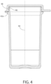
- the lid 24 is pivotable about the hinge 26 with respect to the container body 12 to move the container between a closed position (see, e.g., Figs. 4 or 5 ) in which the lid 24 covers the opening 22 so as to create a moisture tight seal with the body) and an open position (see, e.g., Fig. 1 ) in which the opening 22 is exposed.
- Container body 12 may optionally include outer rim 28 that projects radially outward from the sidewall 16 and completely encircles container body 12 near a top thereof.
- the lip 20 projects vertically from the rim 28.
- the lip 20 has a thickness approximately equal to the remainder of the sidewall 16.
- the lip 20 has a thickness slightly less than that of the remainder of the sidewall 16.
- Lid 24 includes a lid base 30 and preferably a depending skirt 32. Lid 24 further includes a lid outer rim 34 and optionally a thumb tab 36 extending radially from the lid 24. In order to close container 10, the lid 24 is pivoted about the hinge 26 so that the lid 24 covers the opening 22 and engages respective mating sealing surfaces of the lid 24 and body 12, to place lid 24 in closed position.
- Fig. 2 is a sectional view of a container in accordance with a first variation of the container of Fig. 1 .
- Body 12 is shown near the bottom of the figure while lid 24 is shown near the top of the figure.
- the body 12 optionally includes outer rim 28 which projects radially about the circumference of body 12 and near the top of body 12.
- Lid 24 includes lid outer rim 34, optionally projecting radially from the inner portion of the depending skirt 32 of the lid 24.
- lid rim surface 38 faces body rim surface 40.
- body rim surface 40 and at least portions of lid rim surface 38 engage each other.
- elastomer seal 42a is preferably an annular ring disposed around the circumference of body rim surface 40.
- an elastomer-to-thermoplastic seal is created by elastomer seal 42a engaging and being compressed by lid rim surface 38.
- Lid 24 includes lid interior 44, defined by lid base 30 and skirt 32.
- the lip 20 of body 12 extends into lid interior 44 when the lid 24 is in the closed position.
- body undercut surface 46 of body 12 mates with lid undercut surface 48.
- a thermoplastic-to-thermoplastic sealing surface is formed.
- this configuration provides a closing position, e.g., via a snap-fit mating configuration, to retain the lid 24 in the closed position and prevent it from inadvertently opening.
- the thermoplastic-to-thermoplastic seal and the closing position are formed by respective undercut surfaces 46, 48. This may be defined, for example, with reference to an axis 50 (see Fig.
- Lid undercut surface 48 and body undercut surface 46 are not parallel to that axis 50. Rather, as shown, lid undercut surface to 48 and body undercut surface 46 are formed at a slight angle, e.g., from 10° to 30° relative to the axis 50.
- the respective undercut surfaces may alternatively be complimentarily rounded or sloped to mate with each other. With any such undercut configuration, if a user attempts to lift the lid 24 from body 12 to transition the lid 24 to an opened position, an opening force will be required to overcome the force between lid undercut surface 48 and body undercut surface 46 when the lid 24 is in the closed position.
- lid 24 is shown as optionally including lid elastomer seal 52, which is optionally in the form of an annular ring affixed to lid base 30 adjacent to or abutting skirt 32.
- lid elastomer seal 52 is optionally in the form of an annular ring affixed to lid base 30 adjacent to or abutting skirt 32.
- a seal may be formed between lid elastomer seal 52 and top edge 20.
- the container shown in fig. 2 may omit either elastomer seal 52 or elastomer seal 42a, thus providing only a single elastomer-to-thermoplastic seal in an optional embodiment.
- embodiments according to aspects of the invention include multiple and different seals in series between lid 24 and body 12.
- Two seals may comprise the seal between lid undercut surface 48 and body undercut surface 46, and the seal between lid elastomer seal 52 and top edge 20. While three seals (labeled as Seal A - C) are shown in Fig. 2 , this is merely exemplary, as two seals or greater than three seals may be included in accordance with exemplary embodiments of the invention. For example, it is possible for there to be a total of three seals, more than three seals, or only two seals as explained above. Furthermore, at least one of the seals is an elastomer-to-thermoplastic seal and at least one of the seals is a thermoplastic-to-thermoplastic seal.
- thermoplastic-to-thermoplastic seal provides the compression force needed to maintain the elastomer-to-thermoplastic seal.
- This configuration does not require that the elastomer-to-thermoplastic seal be a source of radial compressive force (e.g., as is the case with an elastomeric stopper plugged into a tube).
- the elastomer-to-thermoplastic seal does not add to the opening force necessary to overcome the thermoplastic-to-thermoplastic seal to transition the lid 24 from the closed position to the opened position.
- resilience of the compressed elastomer when the lid 24 is in the closed position may result in a slight vertical spring force biasing the respective undercut surfaces 48, 46 vertically against each other, thus reinforcing or strengthening the thermoplastic-to-thermoplastic seal.
- a slight vertical spring force created by the elastomer-to-thermoplastic seal may tend to actually reduce the opening force compared to an otherwise identical container without an elastomeric sealing surface.
- elastomer seal 42a is affixed to an upper surface of outer rim 28 of the body 12.
- Fig. 3 shows an alternative configuration in which elastomer seal 42b is affixed to lid outer rim 34 and is in contact with outer rim 28 of body 12. In this manner, with regard to the configuration of Fig. 2 and the configuration of Fig. 3 , an elastomer-to-thermoplastic seal is formed.
- Fig. 4 shows the seals which are illustrated in Fig. 2 and further illustrates more of body 12 that is shown in Fig. 2 .
- Fig. 4 is helpful for illustrating the relationship between the sealing surface that is formed between lid undercut surface 48 and body undercut service 46 and central axis 50 which runs along the length of body 12 and through its center.
- lid undercut surface 48 and body undercut surface 46 form an undercut because the seal between these two surfaces is not parallel to central axis 50.
- the undercut between lid undercut surface 48 and body undercut service 46 includes compression force vectors in both vertical and horizontal directions. The vertical compression force vector requires that an opening force be applied in order to separate lid 24 from body 12 and thus transition the lid 24 from the closed position to the opened position.
- Fig. 5 shows the seals which are illustrated in Fig. 3 and further illustrates more of body 12 that is shown in Fig. 3 .
- Fig. 5 is also helpful for illustrating the relationship between the sealing surface that is formed between lid undercut surface 48 and body undercut surface 46 and central axis 50 which runs along the length of body 12 and through its center.
- the configuration and function of respective undercut surfaces 48, 46 of lid 24 and body 12 are identical to those shown in Fig. 4 and are not rehashed here for the sake of brevity.
- thermoplastic-to-thermoplastic seal in series with an elastomer-to-thermoplastic seal according to an aspect of the presently disclosed technology provides an MVTR through the sealing system of a maximum of optionally 42 ⁇ g/day-cm of seal circumference when the ambient conditions are a minimum of 30°C/80% relative humidity (RH) externally and a maximum of 30°C/1% RH internally, while allowing for an opening force of optionally no greater than 3 N/cm of seal circumference.
- RH relative humidity
- FIG. 6-10B there is shown an exemplary embodiment of a container 60 according to the invention.
- Many features of the container 60 of Figs. 6-10B are similar or identical to corresponding features of the container 10 of Figs. 1-5 . Therefore, only a general summary is provided here of such similar or identical corresponding features as with the previously described embodiments. However, key differences as between the embodiments and additional embellishments are noted.
- Container 60 includes a body 62 having a base 64 and optionally a sidewall 66 extending from the base.
- the body 62 defines an interior 68.
- the sidewall 66 optionally terminates at a lip 70 having a top edge 72.
- the lip 70 surrounds an opening 74 of the body 62, leading to the interior 68.
- container body 62 includes outer rim 76.
- the lip 70 optionally projects vertically from the rim 76.
- a lid 78 is connected to the body 62 by a hinge 80, optionally a living hinge, creating a flip-top container 60 or vial.
- the lid 78 is pivotable about the hinge 80 with respect to the container body 62 to move the container 60 between a closed position and an open position.
- lid 62 includes lid base 82 and preferably a depending skirt 84 and thumb tab 86.
- a moisture tight seal 88 is formed by a plurality of engaged mating seals in series, including at least a first seal 90 and a second seal 92.
- the first seal 90 is formed by mating a thermoplastic sealing surface of the body 62 with a thermoplastic sealing surface of the lid 78.
- the first seal 90 is configured to require an opening force to disengage.
- the first seal 90 comprises the engagement of undercut surface 99 of body 62 with undercut surface 97 of lid 78. This seal is identical to the undercut-to-undercut seal disclosed above with respect to the container 10 of Figs. 1-5 and will thus not be elaborated upon further here.
- the second seal 92 is formed by mating a thermoplastic sealing surface of the body 62 or lid 78 with an elastomeric sealing surface of the body 62 or lid 78.
- the second seal 92 is formed by mating a thermoplastic sealing surface of the body 62 with an elastomeric sealing surface of the lid 78.
- the elastomeric sealing surface 94 comprises an elastomeric ring 96 configured to be compressed by a thermoplastic upper surface 72 of a lip 70 surrounding the opening 74 when the lid 78 is in the closed position.
- vertical compression of the elastomeric ring 96 causes a portion of the ring 96 to elastically expand radially into a void 98 provided between the body 62 and the lid 78. This operation is now explained in detail.
- ring can refer to an annular round element with a central opening.
- a “ring” is not necessarily limited to such configuration and could include non-round configurations as well as elastomeric elements that are filled in, at least in part, in the center (i.e., where an opening of a ring may otherwise be).
- a “ring” could include a disc-shaped elastomeric member, for example.
- Fig. 9 shows a partial enlarged cross section of the container 60 with the lid 78 in the closed position.
- the first seal 90 is provided, comprising the engagement of undercut surface 99 of body 62 with undercut surface 97 of lid 78.
- the second seal 92 comprises engagement of the thermoplastic upper surface 72 of the lip 70 with an engagement surface 94 of the elastomeric ring 96 provided on the underside of the base 82 of the lid 78.
- a compression seal provided between the upper surface 72 of the lip 70 and the elastomeric ring 96 causes the cross section of the ring 96 to appear slightly stepped or indented along the engagement surface 94 of the elastomeric ring 96.
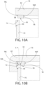
- FIG. 10A shows the cross section of the ring 96 immediately before it contacts the upper surface 72 of the lip 70 to form the second seal.
- the ring 96 when not engaged with the lip, does not have such an indent.
- the indent in the engagement surface 94 of the elastomeric ring 96 is the product of elastomeric deformation of the ring 96 resulting from sealing engagement with the rim 70.
- the elastomeric ring 96 is not bounded or blocked on either an immediate right side 96R or left side 96L thereof.
- a void 98 is provided, e.g., between the elastomeric ring 96 and the skirt 84 of the lid 78 to provide "living space" for the ring material to radially expand when the second seal 92 is engaged.
- Figure 10B illustrates the radially expanded portion 96E of the elastomeric ring 96 (shown expanded in direction E of Fig. 10B ), occupying a portion of the void 98. To the extent such expansion appears in the Figures to be exaggerated compared to actual implementation, it is merely for illustrative purposes. This radial expansion into the void feature provides at least two important functions.
- the second important function is that the surface area of contact between the sealing surfaces of the second seal increases via radial expansion of the ring's elastomeric material. This increase of the elastomer-to-thermoplastic sealing surface area provides a tighter seal at the site of engagement of the second seal.
- a flexible thermoplastic lip seal member may depend downwardly from the base of the lid to abut and thus provide a seal with the interior of the container.
- Such an embodiment may include some or all of the features described in U.S. Pat. No. 9,650,181 .
- such lip seal member abutting the interior of the container may provide an embodiment of a thermoplastic-to-thermoplastic seal within the scope of the disclosed concept.
- the seal formed between the lip seal member and the interior of the container may provide the only moisture tight thermoplastic-to-thermoplastic seal for the container.
- the undercut surface of body and/or undercut surface of lid do not extend completely around the perimeter of the body/lid.
- undercuts may facilitate a closing relationship, e.g., a snap-fit configuration, but may not necessarily establish a moisture tight seal between the undercuts themselves.
- engagement of undercuts provides both a closing relationship, e.g., a snap-fit configuration, as well as a moisture tight seal between the undercuts themselves.
- Ingress Performance for the seal alone is measured by taking the total vial ingress rate and subtracting out the MVTR (moisture vapor transmission rate) through the thermoplastic comprising the outer shell of the vial.
- the moisture vapor transmission rate MVTR is less than 370 ⁇ g/day at 30°C/80% RH (relative humidity).
- the weight of a desiccant entrained three phase polymer sleeve is 2.5-3.25 grams (optionally about 3.0 g) and the moisture ingress is about 400 micrograms per day at 30°C/70% RH.
- the weight of a desiccant entrained three phase polymer sleeve is 2.0-2.75 grams (optionally about 2.5 g) and the moisture ingress is about 300 micrograms per day at 30°C/70% RH.
- volumetric range is provided, e.g., a container having an internal volume of 12mL to 30 mL.
- three phase polymer refers to a desiccant entrained polymer comprising a base polymer, desiccant and channeling agent, e.g., as described in U.S. Pat. Nos. 5,911,937 , 6,080,350 , 6,124,006 , 6,130,263 , 6,194,079 , 6,214,255 , 6,486,231 , 7,005,459 , and U.S. Pat. Pub. No. 2016/003995 .
- the second seal permits reduced use of such desiccant material, resulting in lower manufacturing costs.
- the first seal and the second seal combined provide the container when the lid is in the closed position a lower MVTR than the first seal would provide without the second seal.
- the first seal and the second seal combined provide the container when the lid is in the closed position a lower MVTR than the second seal would provide without the first seal.
- the container is used for storing diagnostic test strips.
- At least one of the thermoplastic-to-thermoplastic sealing surfaces is on a radially-projecting rim along an outside of the body.
- the elastomer has a Shore A hardness from 20 to 50, preferably from 20 to 40, more preferably from 20 to 35.
- a skilled person in the art of injection molding would typically avoid using TPE materials with less than 50 shore A hardness for container seals. This is because such soft TPE materials are generally difficult to adhere to the base polymer without damaging or displacing the seal during molding.
- TPE materials with a hardness of less than 50 shore A for a container seal is made possible.
- Use of such low durometer material creates lower resistance to flow during molding, advantageously creates lower resistance to flow during molding, enabling a thinner cross section.
- the softer TPE material requires less compression force to seal, which reduces the likelihood of excessive vertical spring force, which could otherwise result in inadvertent opening of the container as discussed above.
- the cap opening force is a critical to quality characteristic of the product.
- the acceptable range of opening force is 13.3 to 31.1 Newton (3 to 7 lbf) when measured by affixing the body of the vial standing on the vial base and then applying an upward force to the underside of the bill of the cap, parallel to the axis of the vial at a constant speed of 500 mm/min at a controlled temperature of 20 +/- 2 0 C, with a preferred range of 17.8 to 26.7 Newton (4 to 6 lbf).
- a container that is too easy to open may open inadvertently and a container with an opening force above this range may be too difficult for the user to open.
- the resistance to opening under differential pressure can optionally be measured by placing a container which has been opened and closed in the ambient environment into a sealed chamber and then reducing the external pressure in the chamber over a period of 30 seconds to one minute to create a differential pressure between the interior of the container and the external environment of at least 450 mBar, which is the maximum pressure differential a container should be exposed to during commercial air transportation.
- the elastomer has a thickness of from 0.5 mm to 1.25 mm and optionally an exposed width of the outside vial rim is from 0mm to 2.5mm.
- a vial in accordance with an exemplary embodiment of the disclosed concept may be recycled after use.
- the recycling references the primary material and the chasing arrow corresponds to that recycle class.
- the vial lid seal with thermoplastic elastomer is designed with a lower mass of elastomer to still allow the container to be re-used/ recycled along with the primary material designation.
- An additional elastomer seal thus reduces the moisture vapor transmission rate through the vial container lid seal to allow less required desiccant mass.
- a combination of seals working in series enables reduced moisture vapor transmission, in combination with low lid opening and closing force to optimize the consumer experience.
- a low mass of elastomer within the vial lid seal to allow vial re-use/ recyclability of the vial's primary material.
- first and second seals as disclosed herein may be utilized in elliptical containers, square containers, rectangular containers, quadrilateral containers with rounded corners and many other shapes.
- embodiments of the disclosed concept are utilized with container shapes and configurations disclosed in U.S. Pat. Pub. No. 2011/01 27269 .
- thermoplastic-to-thermoplastic seal (e.g., the first seal 90) is not necessarily limited to the configuration as shown in the accompanying drawing figures.
- the thermoplastic-to-thermoplastic seal may be provided between an inner polymer ring depending from the underside of the lid base and interfacing with a portion of the inner surface of the container body wall.
- an annular protrusion of the inner polymer ring engages a radial undercut within the inner surface of the container body wall to create a variation of the first seal 90 disclosed with respect to Figs. 6-10B . This variation of the first seal would likewise require overcoming an opening force to disengage that seal.
- the addition of the second seal resulted in a meaningful reduction of the mean ingress and a surprisingly significant reduction in the standard deviation of moisture ingress.
- This significant reduction in standard deviation is notable and important from a production standpoint.
- the second seal in combination with the first seal allows for a much more controlled and predictable (i.e., lower variation) moisture ingress so that container moisture budgets can be much more precisely met, resulting in fewer rejected vials.
- This also allows for a reduction in desiccant material necessary per vial and hence a reduction in production costs associated with the reduced amount of desiccant material.
- Example 2 the data show that addition of the second seal resulted in a meaningful reduction of the mean ingress and a surprisingly significant reduction in the standard deviation of moisture ingress.
- the data show that the improved seal arrangement described herein resulted in a meaningful reduction of the mean moisture ingress (i.e., 311.2 ⁇ g/day to 232.3 ⁇ g/day) and a significant reduction in the standard deviation of moisture ingress (i.e., 31.68 to 13.77).
- Fig. 27 shows an additional comparison of the data similar to that of Fig. 26 except measured at 30°C/80% relative humidity) to a sampling of containers of similar design but larger volume (i.e., 24 mL capacity vs. 17 mL capacity). Comparing the data of Figs. 26 and 27 show that mean moisture ingress and standard deviation of moisture ingress increase with increasing relative humidity and/or increasing volume.
- One feature of the disclosed concept is directed to an insert made from an entrained active material for absorbing moisture which penetrates the container.
- such feature is incorporated into a container of any of the embodiments with the sealing configurations discussed above, e.g., as shown in Figs. 1-10B .
- the following definitions and examples explain aspects of such inserts and materials from which such inserts are formed.
- active is defined as capable of acting on, interacting with or reacting with a selected material (e.g., moisture or oxygen). Examples of such actions or interactions may include absorption, adsorption (sorption, generally) or release of the selected material.
- the term "active agent” is defined as a material that (1) is preferably immiscible with the base material (e.g., polymer) and when mixed and heated with the base polymer and the channeling agent, will not melt, i.e., has a melting point that is higher than the melting point for either the base polymer or the channeling agent, and (2) acts on, interacts or reacts with a selected material.
- the term “active agent” may include but is not limited to materials that absorb, adsorb or release the selected material(s).
- Active agents according to the invention may be in the form of particles such as minerals (e.g., molecular sieve or silica gel, in the case of desiccants), but the invention should not be viewed as limited only to particulate active agents.
- an oxygen scavenging formulation may be made from a resin which acts as, or as a component of, the active agent.
- base material is a component (preferably a polymer) of an entrained active material, other than the active agent, that provides structure for the entrained material.
- base polymer is a polymer optionally having a gas transmission rate of a selected material that is substantially lower than, lower than or substantially equivalent to, that of the channeling agent.
- a transmission rate would be a water vapor transmission rate in embodiments where the selected material is moisture and the active agent is a water absorbing desiccant.
- the primary function of the base polymer is to provide structure for the entrained polymer.
- Suitable base polymers may include thermoplastic polymers, e.g., polyolefins such as polypropylene and polyethylene, polyisoprene, polybutadiene, polybutene, polysiloxane, polycarbonates, polyamides, ethylene-vinyl acetate copolymers, ethylene-methacrylate copolymer, poly(vinyl chloride), polystyrene, polyesters, polyanhydrides, polyacrylianitrile, polysulfones, polyacrylic ester, acrylic, polyurethane and polyacetal, or copolymers or mixtures thereof.
- thermoplastic polymers e.g., polyolefins such as polypropylene and polyethylene, polyisoprene, polybutadiene, polybutene, polysiloxane, polycarbonates, polyamides, ethylene-vinyl acetate copolymers, ethylene-methacrylate copolymer, poly(vinyl chloride), polys
- the channeling agent has a water vapor transmission rate of at least two times that of the base polymer. In another embodiment, the channeling agent has a water vapor transmission rate of at least five times that of the base polymer. In another embodiment, the channeling agent has a water vapor transmission rate of at least ten times that of the base polymer. In still another embodiment, the channeling agent has a water vapor transmission rate of at least twenty times that of the base polymer. In still another embodiment, the channeling agent has a water vapor transmission rate of at least fifty times that of the base polymer. In still another embodiment, the channeling agent has a water vapor transmission rate of at least one hundred times that of the base polymer.
- channeling agent or “channeling agents” is defined as a material that is immiscible with the base polymer and has an affinity to transport a gas phase substance at a faster rate than the base polymer.
- a channeling agent is capable of forming channels through the entrained polymer when formed by mixing the channeling agent with the base polymer.
- such channels are capable of transmitting a selected material through the entrained polymer at a faster rate than in solely the base polymer.
- channels or "interconnecting channels” is defined as passages formed of the channeling agent that penetrate through the base polymer and may be interconnected with each other.
- the term "entrained polymer” is defined as a monolithic material formed of at least a base polymer with an active agent and optionally also a channeling agent entrained or distributed throughout.
- An entrained polymer thus includes two-phase polymers and three phase polymers.
- a "mineral loaded polymer” is a type of entrained polymer, wherein the active agent is in the form of minerals, e.g., mineral particles such as molecular sieve or silica gel.
- the term “entrained material” is used herein to connote a monolithic material comprising an active agent entrained in a base material wherein the base material may or may not be polymeric.
- the term "monolithic,” “monolithic structure” or “monolithic composition” is defined as a composition or material that does not consist of two or more discrete macroscopic layers or portions. Accordingly, a “monolithic composition” does not include a multi-layer composite.
- phase is defined as a portion or component of a monolithic structure or composition that is uniformly distributed throughout, to give the structure or composition it's monolithic characteristics.
- the term "selected material” is defined as a material that is acted upon, by, or interacts or reacts with an active agent and is capable of being transmitted through the channels of an entrained polymer.
- the selected material may be moisture or a gas that can be absorbed by the desiccant.
- the selected material may be an agent released by the releasing material, such as moisture, fragrance, or an antimicrobial agent (e.g., chlorine dioxide).
- an adsorbing material is used as an active agent, the selected material may be certain volatile organic compounds and the adsorbing material may be activated carbon.
- three phase is defined as a monolithic composition or structure comprising three or more phases.
- An example of a three phase composition according to the invention would be an entrained polymer formed of a base polymer, active agent, and channeling agent.
- a three phase composition or structure may include an additional phase, e.g., a colorant.
- Entrained polymers may be two phase formulations (i.e., comprising a base polymer and active agent, without a channeling agent) or three phase formulations (i.e., comprising a base polymer, active agent and channeling agent). Entrained polymers are described, for example, in U.S. Pat. Nos. 5,911,937 , 6,080,350 , 6,124,006 , 6,130,263 , 6,194,079 , 6,214,255 , 6,486,231 , 7,005,459 , and U.S. Pat. Pub. No. 2016/0039955 .
- An entrained material or polymer includes a base material (e.g., polymer) for providing structure, optionally a channeling agent and an active agent.
- the channeling agent forms microscopic interconnecting channels through the entrained polymer. At least some of the active agent is contained within these channels, such that the channels communicate between the active agent and the exterior of the entrained polymer via microscopic channel openings formed at outer surfaces of the entrained polymer.
- the active agent can be, for example, any one of a variety of absorbing, adsorbing or releasing materials, as described in further detail below. While a channeling agent is preferred, the invention broadly includes entrained materials that optionally do not include channeling agents, e.g., two phase polymers.
- suitable channeling agents may include a polyglycol such as polyethylene glycol (PEG), ethylene-vinyl alcohol (EVOH), polyvinyl alcohol (PVOH), glycerin polyamine, polyurethane and polycarboxylic acid including polyacrylic acid or polymethacrylic acid.
- the channeling agent can be, for example, a water insoluble polymer, such as a propylene oxide polymerisate-monobutyl ether, such as Polyglykol B01/240, produced by CLARIANT.
- the channeling agent could be a propylene oxide polymerisate monobutyl ether, such as Polyglykol B01/20, produced by CLARIANT, propylene oxide polymerisate, such as Polyglykol D01/240, produced by CLARIANT, ethylene vinyl acetate, nylon 6, nylon 66, or any combination of the foregoing.
- Suitable active agents according to the invention include absorbing materials, such as desiccating compounds. If the active agent is a desiccant, any suitable desiccant for a given application may be used. Typically, physical absorption desiccants are preferred for many applications. These may include molecular sieves (e.g., 4 ⁇ molecular sieve), silica gels, clays and starches. Alternatively, the desiccant may be a chemical compound that forms crystals containing water or compounds which react with water to form new compounds.
- desiccant may be a chemical compound that forms crystals containing water or compounds which react with water to form new compounds.
- the active agent may be an oxygen scavenger, e.g., an oxygen scavenging resin formulation.
- Suitable absorbing materials may also include: (1) metals and alloys such as, but not limited to, nickel, copper, aluminum, silicon, solder, silver, gold; (2) metal-plated particulates such as silver-plated copper, silver-placed nickel, silver-plated glass microspheres; (3) inorganics such as BaTiOs, SrTiOs, SiO 2 , Al 2 O 3 , ZnO, TiO 2 , MnO, CuO, Sb 2 O 3 , WC, fused silica, fumed silica, amorphous fused silica, sol-gel silica, sol-gel titanates, mixed titanates, ion exchange resins, lithium-containing ceramics, hollow glass microspheres; (4) carbon-based materials such as carbon, activated charcoal, carbon black, ketchem black, diamond powder; (5) elastomers, such as polybutadiene, polysiloxane, and semi-metals, ceramic and; (6) other fillers and pigments.
- metals and alloys
- the absorbing material may be a carbon dioxide scavenger, such as calcium oxide.
- the calcium oxide In the presence of moisture and carbon dioxide, the calcium oxide is converted to calcium carbonate. Accordingly, calcium oxide may be used as the absorbing material in applications where absorption of carbon dioxide is needed. Such applications include preserving fresh foods (e.g., fruits and vegetables) that give off carbon dioxide.
- suitable active agents include releasing materials.
- Such materials may comprise any suitable material that will release the selected material from the releasing material.
- the selected material released from the releasing material could be in the form of a solid, gel, liquid or gas.
- These substances can perform a variety of functions including: serving as a fragrance, flavor, or perfume source; supplying a biologically active ingredient such as pesticide, pest repellent, antimicrobials, bait, aromatic medicines, etc.; providing humidifying or desiccating substances; delivering air-borne active chemicals, such as corrosion inhibitors; ripening agents and odor-making agents.
- Suitable biocides for use as releasing materials in the entrained polymers of the disclosed concept may include, but are not limited to, pesticides, herbicides, nematacides, fungicides, rodenticides and/or mixtures thereof.
- active agents may also release nutrients, plant growth regulators, pheromones, defoliants and/or mixture thereof.
- Quaternary ammonium compounds can also be used as releasing materials according to the invention. Such compounds not only function as surfactants, but also impart to the surface of the entrained polymer aseptic properties or establish conditions for reducing the number of microbial organisms, some of which can be pathogenic. Numerous other antimicrobial agents, such as benzalkonium chloride and related types of compounds as hexachlorophene, may also be used as releasing agents according to the invention. Other antimicrobial agents, such as chlorine dioxide releasing agents may be used.
- fragrances including natural, essential oils and synthetic perfumes, and blends thereof.
- Typical perfumery materials which may form part of, or possibly the whole of, the active ingredient include: natural essential oils such as lemon oil, mandarin oil, clove leaf oil, petitgrain oil, cedar wood oil, patchouli oil, lavandin oil, neroli oil, ylang oil, rose absolute or jasmin absolute; natural resins such as labdanum resin or olibanum resin; single perfumery chemicals which may be isolated from natural sources or manufactured synthetically, as for example alcohols such as geraniol, nerol, citronellol, linalol, tetrahydrogeraniol, betaphenylethyl alcohol, methyl phenyl carbinol, dimethyl benzyl carbinol, menthol or cedrol; acetates and other esters derived from such alcohols-aldehydes such as citral, citronellal, hydroxycitronellal, lauric
- the active agent loading level can range from 10% to 80%, preferably 40% to 70%, more preferably from 40% to 60%, and even more preferably from 45% to 55% by weight with respect to the total weight of the entrained polymer.
- channeling agent may be provided in a range of 2% to 10% by weight, preferably about 5%.
- the base polymer may range from 10% to 50% by weight of the total composition, preferably from 20% to 35% by weight.
- a colorant is added, e.g., at about 2% by weight of the total composition.
- Fig. 11 illustrates a container 200 which does not form part of the invention but is referred to for illustrative purposes and which is in accordance with container 10 previously discussed in regard to Fig. 1 . It is noted that optionally, the container 200 of Fig. 11 may incorporate any of the sealing configurations described herein with reference to Figs. 1-10B .
- Container 200 includes a container body 201, a lid 220, and an insert entrained with an active agent, e.g., a desiccant insert 100.
- the exemplary insert 100 is a desiccant insert (i.e., entrained with a desiccant as active agent).
- the insert 100 may alternatively be an oxygen scavenger insert) according to optional embodiments of the disclosed concept.
- Container body 201 and insert 100 are generally cylindrical- shaped, although other three-dimensional (length-wise) shapes are contemplated as well, including elliptical, square, rectangle, prism, etc. It should be appreciated that the insert can be any monolithic composition entrained with an active agent.
- Desiccant insert 100 is comprised of a desiccant that is entrained in another material, e.g., a thermoplastic polymer. Desiccant is incorporated into desiccant insert 100 in various manners that are known to one of ordinary skill in the art. Desiccant insert 100 may be formed, for example in a single-shot injection molding process. Alternatively, desiccant insert 100 may be formed as part of a two-shot molding process in forming a container, wherein one shot forms container body 201 (and optionally lid 220) and another shot forms desiccant insert 100.
- desiccant insert 100 When entraining a desiccant within a rigid polymer matrix to make the insert 100, a moisture impermeable polymer encasement may be created about the individual desiccant particles contained within a structure.
- channeling agents may be combined with a polymer base matrix that is used in the formation of rigid bodies.
- desiccant insert 100 is preferably comprised of a base polymer, the active agent (desiccant) and optionally a channeling agent (i.e., a three-phase desiccant polymer).
- omission of the channeling agent may be desired, so as to provide a two-phase polymer comprising a base polymer and active agent.
- the base polymer into which the desiccant and (optionally) channeling agent are blended to form a monolithic composition include injection moldable thermoplastics, for example, polyethylene or polypropylene.
- the desiccant and channeling agent may be added to the polymer when the polymer base is in a molten state prior to forming it into a container so that these additive agents may be blended and thoroughly mixed throughout the base polymer material. After thoroughly blending the several materials together and the mixing process is subsequently stopped, the channeling agent will separate from the polymer base and form microscopic veins or channels that act as moisture communicating passages throughout the polymer.
- Ethylene-vinyl alcohol (EVOH) and polyvinyl alcohol (PVOH) have been found to be particularly suited as channeling agents for some applications. Each of these alcohols may be mechanically mixed with base polymers, such as polypropylene and polyethylene, and then allowed to separate into domains while still in the molten state.
- the microscopic channels are open at the surface of the polymer structures and thereby provide access for moisture to interior portions of the polymer matrix.
- Insert 100 includes an opening leading to an interior compartment 102 for housing products (e.g., without limitation, medication and diagnostic test strips) and an outer surface 104.
- Interior compartment 102 may have a variety of shapes associated therewith including a shape that corresponds generally to the outer shape of insert 100 (e.g., cup-like).
- the insert 100 is tube-like and without a bottom (not shown) in which case the interior compartment would be open on two ends instead of one.
- Insert 100 further has a top-edge 108 and a bottom end 110 located opposite and distal to top-edge 108. In one configuration top-edge 108 defines an opening leading into interior compartment 102, and bottom end 110 is generally disc-shaped. Insert 100 extends from top-edge 108 to bottom end 110. Bottom end 110 is preferably closed, with the same material used throughout insert 100. However, in some cases, bottom end 110 is deleted (or partially deleted) so that insert 100 is a cylinder with both ends open.
- protrusion(s) e.g., without limitation, detents 112 and ridges 114
- Detents 112 extend from bottom end 110 away from top-edge 108 in order to create space between bottom end 110 and container body 201. Stated differently, detents 112 slightly elevate bottom end 110 from a base 203 of container body 201. By elevating bottom end 110, bottom end 110 is well exposed to air within a void between container body 201 and insert 100. In this manner, and as will be discussed below, bottom end 110 is able to absorb moisture within container body 201.
- ridges 114 may be a plurality of evenly spaced ridges that are situated parallel to each other and extend longitudinally from near the top-edge 108 to near the bottom end 110. In yet another embodiment, ridges 114 do not extend the entire distance from top-edge 108 to bottom end 110. Ridges 114 may extend only part of the distance or may each exist as a line of discontinuous ridges with spaces therebetween. The thickness of ridges 114 may be any of a variety of dimensions. In the example shown in Figs. 2 and 3 , ridges 114 are tapered from top-edge 108 to bottom end 110 ( i . e ., they are thicker towards the top of insert 100 and thinner towards the bottom of insert 100). In an embodiment in which insert 100 is assembled into container body 201 by press fit, tapering of ridges 114 may advantageously facilitate automated insertion of insert 100 into container body 201 upon which upper portions of ridges 114 establish an interference fit with container body 201.
- Insert 100 is optionally rigid and thus not subject to deformation when minimal pressure is applied thereto.
- This optional rigidity may be helpful, for example, in some applications such as when insert 100 is used in combination with an outer container that is not round (and that is for example elliptical, etc.).
- This optional rigidity may provide support to resist deflection about sealing surfaces of non-round (e.g. elliptical) containers (which may promote moisture tightness).
- Non-round containers, e.g., elliptical containers are disclosed in U.S. Pat. Pub. No. 2011/0127269 .
- Moisture tightness may be advantageous to at least partially prevent moisture from entering a container and reducing the efficacy of medicine or test strips included therein.
- moisture ingress When moisture enters a container, moisture ingress has occurred.
- a container in which desiccant is included may be moisture tight.
- moisture tight with respect to a container is defined as a container having a moisture ingress rate of less than 1000 micrograms per day, at 80% relative humidity and 22.2° C. Moisture ingress may thus fall within one of several ranges. One such range is between 25 and 1000 micrograms per day under the aforementioned ambient conditions. Another such range is 50 - 1000 micrograms per day under the aforementioned ambient conditions.
- a further such range is 100 - 1000 micrograms per day under the aforementioned ambient conditions. Still further optional ranges include 100 - 450 micrograms per day, optionally 150-400 micrograms per day, optionally 150-350 micrograms per day, optionally 150-300 micrograms per day, e.g., for a container having an internal volume of 12mL to 30mL, under the aforementioned ambient conditions.
- the following test method may be used: (a) place one gram plus or minus 0.25 grams of molecular sieve in the container and record the weight; (b) fully close the container; (c) place the closed container in an environmental chamber at conditions of 80% relative humidity and 22.2° C; (d) after one day, weigh the container containing the molecular sieve; (e) after four days, weigh the container containing the molecular sieve; and (f) subtract the first day sample from the fourth day sample to calculate the moisture ingress of the container in units of micrograms of water.
- any modification to any of the dimensions associated with insert 100 may result in an increase or decrease in exposed desiccant entrained surface area (or compartmental volume) depending on how the modification is made.
- container body 201 material may be selected from a variety of different materials.
- container body is made from one or more injection moldable plastic materials, e.g., polypropelene or polyethylene.
- Container body 201 includes base 203 and a sidewall 205 extending therefrom.
- Container body 201 has an inner surface 207 that defines an interior 231 of container body 201, and container body 201 further has an opening 233 leading into the interior 231.
- Lid 220 is also included. Lid 220 is separable from container body 201 or preferably, it may be linked to container body 201 by a hinge 240 to form a flip-top container, as shown.
- the lid 220 is pivotable about a hinge axis to move the container 200 between open and closed positions.
- Lid 220 is movable with respect to container body 201 to move container 200 between a closed position in which lid 220 covers the opening 233 of container body 201 and an open position in which the opening 233 is exposed.
- lid 220 is rotated via hinge 240 so that lid 220 seals container body 201.
- Lid 220 has at least one lid sealing surface 221 and container body 201 has at least one body sealing surface 202 located about the opening 233 leading to the interior 231 of container body 201.
- Body sealing surface 202 and lid sealing surface 221 are configured to mate to form a moisture tight seal between lid 220 and container body 201 when container 200 is in the closed position.
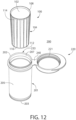
- Fig. 12 illustrates desiccant insert 100 prior to being secured within container body 201.
- desiccant insert 100 can slide into container body 201 through the opening 233 in container body 201.
- the combined use of insert 100 and the illustrated container body 201 embodiment is merely exemplary. It should be understood that desiccant insert 100 may be used with other containers having various shapes, sizes, features, etc.
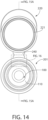
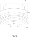
- Fig. 14 illustrates a top view of desiccant insert 100 after it has been inserted into container body 201. It is desirable to maximize the exposed surface area of desiccant insert 100 for moisture absorption as it sits within container body 201. Therefore, as previously described, detents 112 and ridges 114 are included to establish a void between an exposed portion of the outer surface of the insert and a portion of the inner surface of container body, wherein moisture within the void may be absorbed by exposed portion of insert 100.
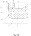
- Fig. 15A shows a section view of container 200 and Fig. 15B shows an enlarged view of a portion of Fig. 15A .
- a void 116 is provided between an exposed portion of outer surface 104 of insert 100 and a portion of inner surface 207 of container body 201. Void 116 is created by virtue of the engagement between detents 112 and ridges 114 with inner surface 207 of container body 201.
- container body 201 may include an annular-shaped retention ring 260 extending radially inwardly from inner surface 207 of container body 201 in order to retain insert 100 within container body 201.
- Retention ring 260 extends slightly beyond the outermost diameter of desiccant insert 100, so that retention ring 260 maintains desiccant insert 100 within container body 201.
- retention ring 260 extends a sufficient amount so that desiccant insert 100 does not fall out of container body 201 when container 200 is inverted and open.
- retention ring 260 extends a sufficient amount so that even when manual force (i.e. greater than gravitational force) is applied, desiccant insert 100 is prevented from sliding out of container 200.
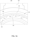
- Fig. 16 shows an enlarged view of a portion of Fig. 14 .
- gaps 118 provide corresponding fluid pathways through which void 116 ( Fig. 15B ) and interior compartment 102 of insert 100 can be in fluid communication.
- air within interior compartment 102 is in fluid communication with (i.e., exposed to and/or able to freely move into) void 116.
- the gaps 118 providing fluid pathways enable air to transfer relatively freely between the interior compartment 102 and the void 116.
- These gaps are distinguishable from the microscopic interconnecting channels through the entrained polymer that facilitate moisture vapor transmission to desiccant contained within the microscopic channels.
- a goal of the illustrative concept is to increase the surface area over which insert 100 is exposed to air in order to facilitate absorption of moisture by desiccant insert 100. Accordingly, by providing at least one fluid pathway (e.g., through gaps 118) between void 116 and interior compartment 102 of insert 100, outer surface 104 is uniquely and advantageously exposed to air within container body 201. This facilitates greater moisture absorption by insert 100, as compared with more conventional containers wherein desiccant inserts are commonly flush with inner surfaces of container bodies and thus cannot absorb moisture from both sides.
- an insert is provided without ridges or detents, and instead a plurality of protrusions are provided on an inner surface of a container body.
- This is essentially an inverse of the configuration wherein the insert has the ridges.
- This alternative also creates a clearance between portions of the inner surface of the container body and the outer surface of the insert, while simultaneously securing insert within container body. In such a configuration, an exposed outer surface of the corresponding insert is exposed to air within the interior compartment for moisture absorption.
- the insert is a blend comprising a base material and a desiccant (or other active agent), as discussed above.
- the invention encompasses inserts that may not include such a blend.
- the insert is composed of a base material (e.g., polymer or rigid paper) with desiccant coated on either surface thereof.
- the insert is made of a polymer with a foaming agent, making it sponge-like.
- the base material is a non-polymeric binder, e.g., clay.
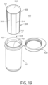
- Figs. 17-19 show different views of a container 400
- Figs. 20 and 21 show different views of a desiccant insert 300 for container 400, in accordance with another non-limiting embodiment of the disclosed concept.
- the container 400 of Fig. 17 incorporates the sealing configurations described herein with reference to Figs. 6-10B .
- Desiccant insert 300 provides substantially the same advantages for container 400 as desiccant insert 100 provides for container 200, discussed above. Accordingly, like components are indicated with like reference numerals.
- desiccant insert 300 in addition to including detents 312 and ridges 314, further includes an annular-shaped lip 309 extending radially outwardly from top-edge 308.
- desiccant insert 300 provides the aforementioned advantages in terms of increased surfaced area ( i.e., via detents 312 and ridges 314) for improved moisture absorption, and further provides additional advantages.
- lip 310 extends from top-edge 308 to an inner surface 407 ( Fig. 19 ) of container body 401 in order to provide a barrier against fluid entry to the space between inner surface 407 ( Fig. 19 ) of container body 401 and an outer surface 304 ( Fig. 19 ) of insert 300.
- bottom end 310 of insert 300 has a plurality of thru holes 315.
- a void substantially akin to void 116 of container 200, shown in Fig. 15B
- container 400 is provided between an exposed portion of outer surface 304 of insert 300 a portion of inner surface 407 of container body 401.
- at least one fluid pathway is provided between the void and an interior compartment 302 ( Fig. 19 ) of insert 300.
- the fluid pathway of exemplary container 400 is provided through thru holes 315.
- thru holes could alternatively or in addition be provided on a sidewall 305 of insert in order to provide a fluid pathway between the void and interior compartment 302 of insert 300.
- the container 200,400 is made in an injection molding process. Such process may be at least in part according to the teachings of U.S. Pat. No. 4,783,056 or U.S. Pat. No. RE 37676 .
- Methods for making a container 200,400 are may include the following steps: (a) providing a container body 201,401 having an opening 233,433 leading to an interior; (b) optionally providing a lid 220,420 that is movable with respect to container body 201,401 to move container 200,400 between a closed position in which lid 220,420 covers the opening 233,433 and an open position in which the opening 233,433 is exposed; (c) securing an insert 100,300 within the interior 231,431 of container body 201,401; (d) forming a void 116 (or void of container 400) between an exposed portion of an outer surface 104,304 of insert 100,300 and a portion of an inner surface 207,407 of container body 201,401; and (e) forming at least one fluid pathway between void 116 ( i.e.
- the securing step may optionally include any one of the following: (i) press-fitting the insert 100,300 into the container body 201,401 optionally before the polymer material of the container body 201,401 is fully set such that container body 201,401 slightly shrinks about insert 100,300; or (ii) overmolding container body 201,401 around insert 100,300; or (iii) employing a two-shot molding process to make container body 201,401 and insert 100,300.
- the insert according to the invention optionally has a faster moisture uptake rate than a comparable insert that is completely flush with the inner wall of the container body.
- the total exposed surface area of the insert 100, 300 (including inner and outer surface) is at least 1.1 times the exposed surface area of the interior compartment 102, 302, optionally at least 1.25 times the exposed surface area of the interior compartment 102, 302, optionally at least 1.5 times the exposed surface area of the interior compartment 102, 302, optionally at least 1.75 times the exposed surface area of the interior compartment 102, 302, optionally at least 2.0 times the exposed surface area of the interior compartment 102, 302, optionally at least 2.5 times the exposed surface area of the interior compartment 102, 302.
- the total exposed surface area of the insert 100, 300 is about 2.2 times the exposed surface area of the interior compartment 102, 302.
- the insert 100, 300 is a single, unitary member, which does not rely on a separate insert or element to provide the void (e.g., 116).
- the void (e.g., 116) is provided between both: (a) the bottom end 110 of the insert 100, 300 and the base 203 of the container body 201; and (b) the outer surface 104,304 of the insert and the sidewall 205 of the container body 201.
- the insert comprises an active agent in addition to or instead of a desiccant, e.g., an oxygen scavenger.
- a desiccant e.g., an oxygen scavenger.
- any of the inserts 100, 300 disclosed herein may be used with the container 60 disclosed herein.
- a container according to an aspect of the disclosed concept would incorporate these features to reduce moisture ingress, improve reliability and consistency of container quality during manufacturing, reduce the amount of desiccant required and improve the efficiency of the desiccant insert's moisture uptake. In this way, an improved vial is provided, which provides desired shelf life for moisture sensitive products, e.g., diagnostic test strips.
- the 17mL Next Generation vial was designed to provide a high quality lower cost alternative to previous vials, while still meeting the performance needs for the protection of blood glucose test strips.
- the ability to reduce costs is based on two key factors:
- the key to the protection of the test strip is to maintain a low relative humidity (RH) over useful life of the test strips.
- RH relative humidity
- the two key factors in vial design are the absorption capacity of the vial and the ability of the vial to block moisture from entering the vial (moisture ingress).
- the ability to absorb an amount of moisture is a function of the type and quantity of desiccant used.
- a standard Activ-Vial TM product it is 4A molecular sieve.
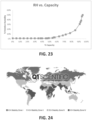
- the relative humidity inside the vial is a function of the % of the molecular sieve's capacity to absorb. This is a fixed property of the desiccant and is well characterized.
- Applicant has characterized this RH vs. Capacity Curve in Applicant's 3-phase desiccant formulation as shown in Fig. 23 .
- the Next Generation 17mL vial which is an optional embodiment of the disclosed concept, is designed to maintain 10% RH throughout the life of the product at a specific set of environmental assumptions that we characterize in our design document we refer to as a Moisture Budget.
- the average ingress requirement over the life of the vial is 346 micrograms/day at 30°C/75% RH with a desiccant sleeve weight requirement of 2.5 grams.
- the average ingress requirement over the life of the vial would be 972 micrograms per day with a desiccant sleeve weight of 6.3 grams. This represents a meaningful difference and savings on manufacturing costs.
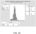
- Vials were tested for 4 weeks at 30°C/75% RH and then each individual ingress value was processed through the model to generate a projection of the average ingress over the life of the vial. The results demonstrated a very high process capability of 2.75. See Fig. 25 . The coefficient of variation for this population is very low at 6%.
- Performance of the Next Generation vial is significantly better compared to the previous vial. Under the design environmental conditions of 30°C/75% RH the average ingress over the shelf life is improved by 25% and the coefficient of variability (Std. Dev/Mean) is reduced by 42%. See Fig. 26 .
- Next Generation vials typically used in the self-monitoring blood glucose market were tested.
- the smaller size is referred to as a 17mL vial or volume and the larger size as a 24mL vial or volume. These sizes are understood by persons of skill in the art.
- Populations of 17mL and 24mL Next Generation vials were tested for overall ingress rate and the results are contained in Fig. 28 .
- the MVTR factor is based on the property of the polymer and the wall thickness this factor was held constant for both vials.
- the tightness or quality of the seal is the primary source of variability and so this factor was calculated separately for each size vial so that the calculated results matched the measured results as closely as possible.
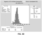
- the UCL (mean + 3* SD) and the LCL (mean - 3*SD) for each population was used to define the variability in the moisture seal ingress performance as measured at 30C/80% RH for 4 weeks on a daily basis and then plotting the data for each vial and using the slope of a fitted linear regression line as the ingress rate for each vial.
- the seal factor for the UCL was increased until the Cpk's of the actual test populations showed a capability to the calculated UCL of approximately a 2.0 (six-sigma capability).
- the ingress performance of the Next Generation vial is significantly better than performance of the previous vial, allowing for a significant reduction in required desiccant mass to meet the requirements of packaging and protecting moisture sensitive blood glucose test strips.
- the performance of the Next Generation vial seal can optionally be defined as having a moisture ingress rate through the seal of less than or equal to 4.3 micrograms/day per linear mm of seal length as measured with an external environment of 30°C+/- 2°C/80%+/5% RH and an internal environment of 30°C +/1 2°C/0%+5% RH when measured over a 4 week period by taking weight measurements on a daily basis using a scale of sufficient precision to measure to .0001 grams, plotting the data and using the slope of the linear regression to define the overall moisture ingress of the vial, then subtracting out the MVTR of the body and cap and dividing by the seal length as measured in mm.
Landscapes
- Engineering & Computer Science (AREA)
- Mechanical Engineering (AREA)
- Food Science & Technology (AREA)
- Closures For Containers (AREA)
- Packages (AREA)
- Medical Preparation Storing Or Oral Administration Devices (AREA)
- Containers And Packaging Bodies Having A Special Means To Remove Contents (AREA)
- External Artificial Organs (AREA)
- Thermotherapy And Cooling Therapy Devices (AREA)
Claims (15)
- Verfahren zum Aufbewahren und Erhalten von feuchtigkeitsempfindlichen Produkten, wobei die Produkte optional Diagnoseteststreifen sind, wobei das Verfahren Folgendes umfasst:(a) Vorsehen eines feuchtigkeitsdichten Behälters (60, 400) der aus einem Polymermaterial gefertigt ist, wobei der Behälter (60, 400) ein Innenvolumen im Bereich von 12 ml bis 30 ml aufweist, wobei der Behälter (60, 400) Folgendes umfasst:(i) einen Behälterkörper (62, 401) mit einem Boden (64) und einer sich davon erstreckenden Seitenwand (66), wobei der Behälterkörper (62, 401) einen Innenraum (68, 431) definiert, wobei der Behälterkörper (62, 401) ferner eine Öffnung (74, 433) aufweist, die in den Innenraum (68, 431) führt;(ii) einen Deckel (78, 420), der durch ein Scharnier (80) mit dem Behälterkörper (62, 401) verbunden ist, wobei der Deckel (78, 420) in Bezug zum Behälterkörper (62, 401) um das Scharnier (80) schwenkbar ist, um den Behälter (60, 400) zwischen einer geschlossenen Position, in welcher der Deckel (78, 420) die Öffnung (74, 433) bedeckt, um einen feuchtigkeitsdichten Verschluss (88) des Behälterkörpers (62, 401) zu erzeugen, und einer geöffneten Position, in welcher die Öffnung (74, 433) freiliegt, zu bewegen; und(iii) einen Einsatz (100, 300), der innerhalb des Innenraums (68, 431) des Behälterkörpers (62, 401) fixiert ist, wobei der Einsatz (100, 300) ein Grundmaterial und ein Trocknungsmittel umfasst, wobei das Grundmaterial dem Einsatz (100, 300) eine Struktur verleiht und optional ein Polymer ist, wobei der Einsatz (100, 300) eine Einsatzöffnung aufweist, die zu einer Innenkammer (102, 302) führt, die zur Aufnahme feuchtigkeitsempfindlicher Produkte ausgelegt ist;(b) Anordnen mehrerer feuchtigkeitsempfindlicher Produkte, optional Diagnoseteststreifen, in der Innenkammer (102, 302), wenn sich der Behälter (60, 400) in der geöffneten Position befindet; und(c) Bewegen des Behälters (60, 400) in die geschlossene Position, dadurch Erzeugen des feuchtigkeitsdichten Verschlusses (88) zwischen dem Deckel (78, 420) und dem Behälterkörper (62, 401);wobei:(aa) der Behälter (60, 400) den feuchtigkeitsempfindlichen Produkten eine Lebensdauer von mindestens 12 Monaten, optional von mindestens 18 Monaten, optional von mindestens 24 Monaten, optional von 18 Monaten bis 36 Monaten, verleiht;(bb) der Behälter (60, 400) in der geschlossenen Position bei einer Umgebungstemperatur von 30 °C und 75 % relativer Luftfeuchtigkeit (RH) eine Wasserdampfdurchlässigkeit von weniger als 500 µg/Tag, optional weniger als 400 µg/Tag, optional weniger als 350 µg/Tag, optional weniger als 325 µg/Tag, optional weniger als 300 µg/Tag, optional von 150 pg/Tag bis 300 µg/Tag, optional 175 pg/Tag bis 285 µg/Tag, aufweist; und(cc) der Einsatz (100, 300) eine Masse von weniger als 3,25 g, optional 1,5 g bis 3 g, optional 1,5 g bis 2,75 g, optional 1,75 g bis 2,75 g, optional 2 g bis 2,75 g, optional etwa 2,5 g, aufweist;und wobei der feuchtigkeitsdichte Verschluss (88) mehrere eingegriffene Verbindungsverschlüsse nacheinander zwischen dem Behälterkörper (62, 401) und dem Deckel (78, 420) umfasst, wenn sich der Behälter (60, 400) in der geschlossenen Position befindet, wobei die mehreren eingegriffenen Verbindungsverschlüsse mindestens einen ersten Verschluss (90) und einen zweiten Verschluss (92) umfassen;
wobei:(i) der erste Verschluss (90) durch Verbinden einer thermoplastischen Verschlussfläche des Behälterkörpers (62, 401) mit einer thermoplastischen Verschlussfläche des Deckels (78, 420) ausgebildet wird,(ii) der zweite Verschluss (92) durch Verbinden einer thermoplastischen Verschlussfläche des Behälterkörpers (62, 401) mit einer elastomerischen Verschlussfläche (94) des Deckels (78, 420) ausgebildet wird, wobei die elastomerische Verschlussfläche (94) einen elastomerischen Ring (96) umfasst, optional umfassend ein thermoplastisches Elastomer (TPE), das dazu ausgelegt ist, durch eine obere Fläche eines die Öffnung (74, 433) umgebenden Rands komprimiert zu werden, wenn sich der Behälter (60, 400) in der geschlossenen Position befindet, wobei die vertikale Kompression des elastomerischen Rings (96) bewirkt, dass sich ein Abschnitt des Rings (96) radial in einen zwischen dem Behälterkörper (62, 401) und dem Deckel (78, 420) vorgesehenen Hohlraum (98) elastisch ausdehnt, wobei der elastomerische Verschlussring optional eine Shore-A-Härte von 20 bis 50, optional von 20 bis 40, optional von 20 bis 35, aufweist. - Verfahren nach Anspruch 1, dadurch gekennzeichnet, dass der Behälter (60, 400) eine Öffnungskraft erfordert, um den Behälter (60, 400) von der geschlossenen Position in die geöffnete Position zu bringen, wobei die Öffnungskraft von 13,3 bis 31,1 Newton (3 bis 7 Ibf (Pound-force)), optional von 17,8 bis 26,7 Newton (4 bis 6 lbf), beträgt und/oder wobei der erste Verschluss (90) eine Öffnungskraft erfordert, um den Behälter (60, 400) von der geschlossenen Position in die geöffnete Position zu bringen, und der zweite Verschluss (92) in Kombination mit dem ersten Verschluss (90) keine Kraft erfordert, die größer ist als die Öffnungskraft, um den Behälter (60, 400) von der geschlossenen Position in die geöffnete Position zu bringen.
- Verfahren nach Anspruch 1 oder 2, dadurch gekennzeichnet, dass der erste Verschluss (90) eine Unterschneidung des Behälterkörpers (62, 401) in Bezug zu einer Mittelachse (50) des Behälterkörpers (62, 401) aufweist, wobei die Unterschneidung in einer Lippe (70) vorgesehen ist, die sich von der Seitenwand (66) aufwärts erstreckt und die Öffnung (74, 433) umgibt, wobei der Deckel (78, 420) eine herabhängende Schürze (84) umfasst, wobei die Unterschneidung eine Fläche (99) aufweist, die sich mit einer zugehörigen Fläche (97) der Schürze (84) verbindet und dadurch den ersten Verschluss (90) ausbildet.
- Verfahren nach einem der vorstehenden Ansprüche, dadurch gekennzeichnet, dass eine Unterschneidungsfläche (99) des Behälterkörpers (62, 401) in einem Einrastverschlussverhältnis in eine Unterschneidungsfläche (97) des Deckels (78, 420) eingreift.
- Verfahren nach einem der vorstehenden Ansprüche, dadurch gekennzeichnet, dass ein Hohlraum (116) zwischen einem freiliegenden Abschnitt einer Außenfläche (104, 304) des Einsatzes (100, 300) und einem Abschnitt einer Innenfläche (407) des Behälterkörpers (62, 401) vorgesehen ist und wobei mindestens ein Fluiddurchgang zwischen dem Hohlraum (116) und der Innenkammer (102, 302) des Einsatzes (100, 300) vorgesehen ist.
- Feuchtigkeitsdichter Behälter (60, 400), wobei der Behälter (60, 400) ein Innenvolumen im Bereich von 12 ml bis 30 ml aufweist, wobei der Behälter (60, 400) Folgendes umfasst:(a) einen Behälterkörper (12, 62, 201, 401) mit einem Boden (64) und einer sich davon erstreckenden Seitenwand (66), wobei der Behälterkörper (62, 401) einen Innenraum (68, 431) definiert, wobei der Behälterkörper (62, 401) ferner eine Öffnung (74, 433), die in das Innere (68, 431) führt, und eine die Öffnung (74, 431) umgebende Lippe (70) aufweist;(b) einen Deckel (78, 420), der im Bezug zum Behälter (60, 400) zwischen einer geschlossenen Position, in welcher der Deckel (78, 420) die Öffnung (74, 433) bedeckt, um einen feuchtigkeitsdichten Verschluss (88) des Behälterkörpers (62, 401) zu erzeugen, und einer geöffneten Position, in welcher die Öffnung (74, 433) freiliegt, beweglich ist;(c) mindestens einen ersten Verschluss (90) und einen zweiten Verschluss (92), wobei der erste Verschluss (90) durch gegenseitiges Verbinden von thermoplastischen Verschlussflächen des Deckels (78, 420) bzw. des Behälterkörpers (62, 401) ausgebildet ist, wobei der erste Verschluss (90) optional eine Unterschneidung des Behälterkörpers (62, 401) in Bezug zu einer Mittelachse (50) des Behälterkörpers (62, 401) oder ein Lippenverschlusselement, das sich vom Deckel (78, 420) abwärts erstreckt, umfasst, wobei der zweite Verschluss (92) durch Verbinden von elastischen und thermoplastischen Verschlussflächen ausgebildet ist, wobei die elastischen und thermoplastischen Verschlussflächen ein im Deckel (78, 420) oder am Behälterkörper ausgebildetes Elastomer umfassen, optional mittels Multi-Shot-Spritzgießens, wobei der Thermoplast nicht komprimierbar ist und das Elastomer komprimierbar und optional elastisch ist; und(d) einen Einsatz (100, 300), der innerhalb des Innenraums (68, 431) des Behälterkörpers (62, 401) fixiert ist, wobei der Einsatz (100, 300) ein Grundmaterial und ein Trocknungsmittel umfasst, wobei das Grundmaterial dem Einsatz (100, 300) eine Struktur verleiht und optional ein Polymer ist, wobei der Einsatz (100, 300) eine Einsatzöffnung aufweist, die zu einer Innenkammer (102, 302) führt, die zur Aufnahme von Produkten ausgelegt ist;wobei:(i) der Behälter (60, 400) in der geschlossenen Position bei einer Umgebungstemperatur von 30 °C und 75 % relativer Luftfeuchtigkeit (RH) eine Wasserdampfdurchlässigkeit von weniger als 500 µg/Tag, optional weniger als 400 µg/Tag, optional weniger als 350 µg/Tag, optional weniger als 325 µg/Tag, optional weniger als 300 µg/Tag, optional von 150 pg/Tag bis 300 µg/Tag, optional 175 pg/Tag bis 285 µg/Tag, aufweist;(ii) der Einsatz (100, 300) eine Masse von weniger als 3,25 g, optional 1,5 g bis 3 g, optional 1,5 g bis 2,75 g, optional 1,75 g bis 2,75 g, optional 2 g bis 2,75 g, optional etwa 2,5 g, aufweist; und(iii) der Behälter (60, 400) ein Polymermaterial umfasstund wobei der zweite Verschluss (92) durch Verbinden einer thermoplastischen Verschlussfläche des Behälterkörpers (62, 401) mit einer elastomerischen Verschlussfläche (94) des Deckels (78, 420) ausgebildet wird, wobei die elastomerische Verschlussfläche (94) einen elastomerischen Ring (96) umfasst, optional umfassend ein thermoplastisches Elastomer (TPE), das dazu ausgelegt ist, durch eine obere Fläche eines die Öffnung (74, 433) umgebenden Rands komprimiert zu werden, wenn sich der Behälter (60, 400) in der geschlossenen Position befindet, wobei die vertikale Kompression des elastomerischen Rings (96) bewirkt, dass sich ein Abschnitt des Rings (96) radial in einen zwischen dem Behälterkörper (62, 401) und dem Deckel (78, 420) vorgesehenen Hohlraum (98) elastisch ausdehnt, wobei der elastomerische Verschlussring (96) optional eine Shore-A-Härte von 20 bis 50, optional von 20 bis 40, optional von 20 bis 35, aufweist.
- Behälter (60, 400) nach Anspruch 6, dadurch gekennzeichnet, dass der Deckel (78, 420) durch ein Scharnier (80) mit dem Behälterkörper (62, 401) verbunden ist, wobei der Deckel (78, 420) in Bezug zum Behälterkörper (62, 401) um das Scharnier (80) schwenkbar ist, um den Behälter (60, 400) zwischen der geschlossenen Position und der geöffneten Position zu bewegen.
- Behälter (60, 400) nach Anspruch 6 oder 7, dadurch gekennzeichnet, dass der Behälter (60, 400) eine Öffnungskraft erfordert, um den Behälter (60, 400) von der geschlossenen Position in die geöffnete Position zu bewegen,wobei die Öffnungskraft von 13,3 bis 31,1 Newton (3 bis 7 lbf (Pound-force)), optional von 17,8 bis 26,7 Newton (4 bis 6 lbf), beträgt und/oderwobei der erste Verschluss (90) eine Öffnungskraft erfordert, um den Behälter (60, 400) von der geschlossenen Position in die geöffnete Position zu bringen, und der zweite Verschluss (92) in Kombination mit dem ersten Verschluss (90) keine Kraft erfordert, die größer ist als die Öffnungskraft, um den Behälter (60, 400) von der geschlossenen Position in die geöffnete Position zu bringen.
- Behälter (60, 400) nach einem der Ansprüche 6-8, dadurch gekennzeichnet, dass ein Hohlraum (116) zwischen einem freiliegenden Abschnitt einer Außenfläche (104, 304) des Einsatzes (100, 300) und einem Abschnitt einer Innenfläche (407) des Behälterkörpers (62, 401) vorgesehen ist, und wobei mindestens ein Fluiddurchgang zwischen dem Hohlraum (116) und der Innenkammer (102, 302) des Einsatzes (100, 300) vorgesehen ist.
- Behälter (60, 400) nach Anspruch 9, dadurch gekennzeichnet, dass der Einsatz (100, 300) ferner einen unteren Endabschnitt (110, 310) und einen dem unteren Endabschnitt (110, 310) entgegengesetzt angeordneten Oberkantenabschnitt (108, 308) aufweist; wobei der Oberkantenabschnitt (108, 308) die Öffnung definiert, die in die Innenkammer (102, 302) führt; und wobei der mindestens eine Fluiddurchgang durch: a) mindestens eine Durchgangsbohrung (315) im Einsatz (100, 300) und/oder b) mindestens einen Spalt (118) zwischen dem Oberkantenabschnitt (108, 308) und der Innenfläche (407) des Behälterkörpers (62, 401) vorgesehen ist.
- Behälter (60, 400) nach Anspruch 9 oder 10, dadurch gekennzeichnet, dass mehrere Vorsprünge vorgesehen sind auf: a) der Außenfläche (104, 304) des Einsatzes (100, 300) und/oder b) der Innenfläche (407) des Behälterkörpers (62, 401); wobei die mehreren Vorsprünge in die Innenfläche (407) des Behälterkörpers (62, 401) eingreifen.
- Behälter (60, 400) nach Anspruch 11, dadurch gekennzeichnet, dass die mehreren Vorsprünge Rippen (114, 314) umfassen, die auf der Außenfläche (104, 304) des Einsatzes (100, 300) vorgesehen sind; und wobei sich die Rippen (114, 314) in Längsrichtung von in der Nähe des Oberkantenabschnitts (108, 308) in die Nähe des unteren Endabschnitts (110, 310) erstrecken.
- Behälter (60, 400) nach einem der Ansprüche 6-12, dadurch gekennzeichnet, dass der Einsatz (100, 300) ein versetztes Polymer ist, das ferner ein kanalbildendes Mittel umfasst.
- Behälter nach einem der Ansprüche 6-13, dadurch gekennzeichnet, dass der Einsatz (100, 300) eine freiliegende Gesamtoberfläche aufweist, die zumindest das 1,75-Fache, optional zumindest das 2,0-Fache, einer freiliegenden Oberfläche der Innenkammer (102, 302) beträgt.
- Verwendung eines Behälters (60, 400) nach einem der Ansprüche 6-14 zur Aufbewahrung von Diagnoseteststreifen.
Applications Claiming Priority (3)
| Application Number | Priority Date | Filing Date | Title |
|---|---|---|---|
| US201762542391P | 2017-08-08 | 2017-08-08 | |
| US201762542358P | 2017-08-08 | 2017-08-08 | |
| PCT/US2018/045697 WO2019032636A1 (en) | 2017-08-08 | 2018-08-08 | HUMIDITY-CONTAINING CONTAINERS AND METHODS OF MAKING AND USING THE SAME |
Publications (2)
| Publication Number | Publication Date |
|---|---|
| EP3665102A1 EP3665102A1 (de) | 2020-06-17 |
| EP3665102B1 true EP3665102B1 (de) | 2024-10-02 |
Family
ID=63407532
Family Applications (1)
| Application Number | Title | Priority Date | Filing Date |
|---|---|---|---|
| EP18762203.0A Active EP3665102B1 (de) | 2017-08-08 | 2018-08-08 | Feuchtigkeitsdichte behälter und verfahren zu ihrer verwendung |
Country Status (11)
| Country | Link |
|---|---|
| US (1) | US11325771B2 (de) |
| EP (1) | EP3665102B1 (de) |
| JP (1) | JP7228566B2 (de) |
| KR (1) | KR20200077506A (de) |
| CN (1) | CN111164023B (de) |
| BR (1) | BR112020002383B1 (de) |
| CA (1) | CA3072432C (de) |
| MX (1) | MX2020001362A (de) |
| SG (1) | SG11202000838SA (de) |
| TW (1) | TWI791584B (de) |
| WO (1) | WO2019032636A1 (de) |
Families Citing this family (18)
| Publication number | Priority date | Publication date | Assignee | Title |
|---|---|---|---|---|
| CN102026890B (zh) * | 2008-05-15 | 2012-05-09 | Csp技术公司 | 容器、用于材料条的分配器以及一种制造分配器的方法 |
| US11033133B2 (en) * | 2018-05-04 | 2021-06-15 | Michael J. O'Hare | Thermal travel container for use with or without disposable cups |
| IT201900007746A1 (it) * | 2019-05-31 | 2020-12-01 | Sacmi | Tappo con cerniera per un contenitore. |
| EP4085013A1 (de) * | 2020-01-03 | 2022-11-09 | Airnov, Inc. | Anordnung zur definition einer kammer für ein aktives material |
| US20210300626A1 (en) * | 2020-02-03 | 2021-09-30 | Ronda Shamansky | Compact ingredient container |
| WO2021163198A1 (en) * | 2020-02-10 | 2021-08-19 | Eco.Logic Brands Inc. | Modular container with improved performance |
| CN112137551A (zh) * | 2020-10-23 | 2020-12-29 | 珠海格力电器股份有限公司 | 电解组件的出线结构、电解装置及洗碗机 |
| CN114468926A (zh) * | 2020-10-23 | 2022-05-13 | 珠海格力电器股份有限公司 | 洗碗机的电解组件、电解装置及洗碗机 |
| USD997717S1 (en) | 2020-11-24 | 2023-09-05 | Csp Technologies, Inc. | Container |
| USD1024790S1 (en) * | 2021-10-19 | 2024-04-30 | Csp Technologies, Inc. | Container |
| TWD223631S (zh) * | 2021-11-22 | 2023-02-11 | 大陸商塞納醫藥包裝材料(崑山)有限公司 | 氣密容器 |
| CN118475516A (zh) * | 2021-12-31 | 2024-08-09 | 艾尔诺沃股份有限公司 | 限定用于活性材料的腔室的组件以及用于制造这种组件的方法 |
| CA3254875A1 (en) * | 2022-07-06 | 2024-01-11 | Csp Technologies, Inc. | SECONDARY PACKAGING DESIGNED TO CONTAIN A MEDICATION ADMINISTRATION DEVICE AND/OR PREVENT ITS ACCIDENTAL ACTIVATION |
| CN119562925A (zh) * | 2022-07-07 | 2025-03-04 | 许东奎 | 环保容器 |
| EP4393837B1 (de) * | 2022-12-30 | 2025-10-29 | Airnov, Inc. | Originalitätsverschluss |
| US12304709B2 (en) * | 2023-01-17 | 2025-05-20 | Silipint Partners Llc | Self-venting lid for containers |
| US20240268455A1 (en) * | 2023-02-09 | 2024-08-15 | JAWK Holdings Inc. | Adaptable Electronic Cigarette Case |
| CN119568567A (zh) * | 2023-09-07 | 2025-03-07 | 浙江阿克希龙舜华铝塑业有限公司 | 金属包装盒 |
Family Cites Families (37)
| Publication number | Priority date | Publication date | Assignee | Title |
|---|---|---|---|---|
| US4116352A (en) * | 1976-11-01 | 1978-09-26 | Leonard Russo | Sealing device |
| US4783056A (en) | 1986-11-10 | 1988-11-08 | Abrams Robert S | Process for making an aseptic vial and cap |
| EP0487448A1 (de) | 1990-11-19 | 1992-05-27 | Treff Ag | Reaktionsgefäss aus Kunststoff für kleine Flüssigkeitsmengen |
| USRE37676E1 (en) | 1994-10-14 | 2002-04-30 | Capitol Vial, Inc. | Process and apparatus for making a leak proof cap and body assembly |
| US6080350A (en) | 1995-04-19 | 2000-06-27 | Capitol Specialty Plastics, Inc. | Dessicant entrained polymer |
| US6130263A (en) | 1995-04-19 | 2000-10-10 | Capitol Specialty Plastics, Inc. | Desiccant entrained polymer |
| US6214255B1 (en) | 1995-04-19 | 2001-04-10 | Capitol Specialty Plastics, Inc. | Desiccant entrained polymer |
| US6124006A (en) | 1995-04-19 | 2000-09-26 | Capitol Specialty Plastics, Inc. | Modified polymers having controlled transmission rates |
| US5911937A (en) | 1995-04-19 | 1999-06-15 | Capitol Specialty Plastics, Inc. | Desiccant entrained polymer |
| US6174952B1 (en) | 1995-04-19 | 2001-01-16 | Capitol Specialty Plastics, Inc. | Monolithic polymer composition having a water absorption material |
| US6221446B1 (en) | 1995-04-19 | 2001-04-24 | Capitol Specialty Plastics, Inc | Modified polymers having controlled transmission rates |
| US6194079B1 (en) | 1995-04-19 | 2001-02-27 | Capitol Specialty Plastics, Inc. | Monolithic polymer composition having an absorbing material |
| US6486231B1 (en) | 1995-04-19 | 2002-11-26 | Csp Technologies, Inc. | Co-continuous interconnecting channel morphology composition |
| DE19546684A1 (de) * | 1995-12-14 | 1997-06-19 | Boehringer Mannheim Gmbh | Vorratsbehältnis für streifenförmige Testelemente |
| TW341227U (en) * | 1997-09-22 | 1998-09-21 | Jiuh Hann Plastics Entpr Co Ltd | An airtight can for drying agents |
| US7537137B2 (en) | 2002-10-10 | 2009-05-26 | Csp Technologies, Inc. | Resealable moisture tight container assembly for strips and the like having a lip snap seal |
| JP4200730B2 (ja) * | 2002-10-18 | 2008-12-24 | 凸版印刷株式会社 | 吸収能力付与容器 |
| JP2004142778A (ja) * | 2002-10-24 | 2004-05-20 | Toppan Printing Co Ltd | 吸収能力付与容器 |
| US7950546B2 (en) * | 2004-10-20 | 2011-05-31 | Csp Technologies, Inc. | Re-sealable moisture tight containers for strips and the like having alternative sealing mechanisms |
| DK2207727T3 (en) * | 2007-11-16 | 2016-06-20 | Clariant Production (France) S A S | Container |
| CN102026890B (zh) | 2008-05-15 | 2012-05-09 | Csp技术公司 | 容器、用于材料条的分配器以及一种制造分配器的方法 |
| FR2949445B1 (fr) * | 2009-08-31 | 2011-11-25 | Urgo Lab | Contenant hermetique |
| US8622231B2 (en) | 2009-09-09 | 2014-01-07 | Roche Diagnostics Operations, Inc. | Storage containers for test elements |
| TWI374841B (en) | 2009-12-01 | 2012-10-21 | Tsai Feng Der | Desiccating container |
| WO2013070664A1 (en) * | 2011-11-09 | 2013-05-16 | Csp Technologies, Inc. | Container with insert |
| HUE028522T2 (en) * | 2012-02-28 | 2016-12-28 | Clariant Production (France) S A S | Container for receiving moisture sensitive items |
| CA3128559C (en) * | 2013-01-23 | 2023-12-19 | Csp Technologies, Inc. | Packaging sealing system and a packaging assembly including such a sealing system |
| US9533803B1 (en) * | 2013-06-04 | 2017-01-03 | Csp Technologies, Inc. | Container having a child resistant closure with a small profile |
| EP2961666B1 (de) * | 2013-03-01 | 2019-01-09 | CSP Technologies, Inc. | Behälter mit einsätzen |
| CN105073876A (zh) | 2013-03-14 | 2015-11-18 | Csp技术公司 | 形成夹带聚合物中的通道的试剂、含有此种试剂的夹带聚合物、用于生产此种夹带聚合物的方法以及含有此种夹带聚合物的产品 |
| JP5825334B2 (ja) * | 2013-12-18 | 2015-12-02 | 凸版印刷株式会社 | 吸湿能力を有する樹脂成型体およびこれを用いた乾燥容器 |
| DK2966000T3 (en) * | 2014-07-08 | 2016-10-24 | Clariant Production (France) S A S | Container |
| US20160031627A1 (en) | 2014-08-04 | 2016-02-04 | Huan-Fu Yeh | Moisture Proof Container |
| CN105460347A (zh) | 2014-09-11 | 2016-04-06 | 钱国华 | 一种包装瓶 |
| US10065772B2 (en) * | 2015-04-28 | 2018-09-04 | Sanner Gmbh | Container comprising two sealing segments |
| AU2017228453B2 (en) * | 2016-03-04 | 2020-04-30 | Csp Technologies, Inc. | Container and lid |
| FR3063282B1 (fr) * | 2017-02-24 | 2020-11-20 | Clariant Healthcare Packaging France Sas | Recipient pour produits medicaux et/ou pharmaceutiques |
-
2018
- 2018-08-08 EP EP18762203.0A patent/EP3665102B1/de active Active
- 2018-08-08 CN CN201880064736.1A patent/CN111164023B/zh active Active
- 2018-08-08 WO PCT/US2018/045697 patent/WO2019032636A1/en not_active Ceased
- 2018-08-08 SG SG11202000838SA patent/SG11202000838SA/en unknown
- 2018-08-08 US US16/637,623 patent/US11325771B2/en active Active
- 2018-08-08 KR KR1020207006496A patent/KR20200077506A/ko not_active Ceased
- 2018-08-08 JP JP2020506790A patent/JP7228566B2/ja active Active
- 2018-08-08 MX MX2020001362A patent/MX2020001362A/es unknown
- 2018-08-08 BR BR112020002383-3A patent/BR112020002383B1/pt active IP Right Grant
- 2018-08-08 CA CA3072432A patent/CA3072432C/en active Active
- 2018-08-08 TW TW107127553A patent/TWI791584B/zh active
Also Published As
| Publication number | Publication date |
|---|---|
| JP2020530426A (ja) | 2020-10-22 |
| WO2019032636A1 (en) | 2019-02-14 |
| JP7228566B2 (ja) | 2023-02-24 |
| CN111164023B (zh) | 2022-09-09 |
| US20200255206A1 (en) | 2020-08-13 |
| TW201919961A (zh) | 2019-06-01 |
| BR112020002383B1 (pt) | 2022-10-11 |
| MX2020001362A (es) | 2020-03-20 |
| EP3665102A1 (de) | 2020-06-17 |
| TWI791584B (zh) | 2023-02-11 |
| SG11202000838SA (en) | 2020-02-27 |
| US11325771B2 (en) | 2022-05-10 |
| KR20200077506A (ko) | 2020-06-30 |
| CA3072432A1 (en) | 2019-02-14 |
| CN111164023A (zh) | 2020-05-15 |
| BR112020002383A2 (pt) | 2020-09-01 |
| CA3072432C (en) | 2024-05-21 |
Similar Documents
| Publication | Publication Date | Title |
|---|---|---|
| US11325771B2 (en) | Moisture tight containers and methods of making and using the same | |
| US10974887B2 (en) | Containers, container inserts and associated methods for making containers | |
| US20210323749A1 (en) | Resealable moisture tight container assembly for strips and the like having a lip snap seal | |
| JP2021098549A (ja) | 容器および蓋 | |
| US20040173612A1 (en) | Resealable moisture tight containers for strips and the like | |
| JP2021519706A (ja) | 軟質材料を硬質材料によりオーバーモールドする方法及びその方法によって作成される湿密容器アセンブリ | |
| US20250248895A1 (en) | Medication delivery systems and methods | |
| KR20200124219A (ko) | 틈새를 가진 의료 및/또는 의약 제품들을 위한 용기 | |
| US20250134771A1 (en) | Secondary packaging configured to hold and/or prevent inadvertent actuation of a device for administering a drug | |
| US11767153B2 (en) | Mineral entrained plastic formulations as puncturing elements | |
| CN119907771A (zh) | 用于储存和稳定水分敏感性产品的容器和方法 | |
| CA3014076C (en) | Containers, container inserts and associated methods for making containers | |
| HK40001434B (en) | Containers, container inserts and associated methods for making containers | |
| JP4036443B2 (ja) | 粉末エアゾール用定量噴射装置 | |
| WO2023077060A1 (en) | Container, dispenser, and method of making and using same | |
| US20210316087A1 (en) | Low odor or no odor inhaler desiccant polymer | |
| HK40026089B (en) | Mineral entrained plastic formulations as puncturing elements | |
| HK40026089A (en) | Mineral entrained plastic formulations as puncturing elements |
Legal Events
| Date | Code | Title | Description |
|---|---|---|---|
| STAA | Information on the status of an ep patent application or granted ep patent |
Free format text: STATUS: UNKNOWN |
|
| STAA | Information on the status of an ep patent application or granted ep patent |
Free format text: STATUS: THE INTERNATIONAL PUBLICATION HAS BEEN MADE |
|
| PUAI | Public reference made under article 153(3) epc to a published international application that has entered the european phase |
Free format text: ORIGINAL CODE: 0009012 |
|
| STAA | Information on the status of an ep patent application or granted ep patent |
Free format text: STATUS: REQUEST FOR EXAMINATION WAS MADE |
|
| 17P | Request for examination filed |
Effective date: 20200224 |
|
| AK | Designated contracting states |
Kind code of ref document: A1 Designated state(s): AL AT BE BG CH CY CZ DE DK EE ES FI FR GB GR HR HU IE IS IT LI LT LU LV MC MK MT NL NO PL PT RO RS SE SI SK SM TR |
|
| AX | Request for extension of the european patent |
Extension state: BA ME |
|
| DAV | Request for validation of the european patent (deleted) | ||
| DAX | Request for extension of the european patent (deleted) | ||
| REG | Reference to a national code |
Ref country code: HK Ref legal event code: DE Ref document number: 40030203 Country of ref document: HK |
|
| STAA | Information on the status of an ep patent application or granted ep patent |
Free format text: STATUS: EXAMINATION IS IN PROGRESS |
|
| 17Q | First examination report despatched |
Effective date: 20220929 |
|
| P01 | Opt-out of the competence of the unified patent court (upc) registered |
Effective date: 20230621 |
|
| GRAP | Despatch of communication of intention to grant a patent |
Free format text: ORIGINAL CODE: EPIDOSNIGR1 |
|
| STAA | Information on the status of an ep patent application or granted ep patent |
Free format text: STATUS: GRANT OF PATENT IS INTENDED |
|
| RIC1 | Information provided on ipc code assigned before grant |
Ipc: B65D 43/16 20060101ALI20230925BHEP Ipc: B65D 53/02 20060101ALI20230925BHEP Ipc: B65D 81/26 20060101AFI20230925BHEP |
|
| INTG | Intention to grant announced |
Effective date: 20231010 |
|
| GRAJ | Information related to disapproval of communication of intention to grant by the applicant or resumption of examination proceedings by the epo deleted |
Free format text: ORIGINAL CODE: EPIDOSDIGR1 |
|
| STAA | Information on the status of an ep patent application or granted ep patent |
Free format text: STATUS: EXAMINATION IS IN PROGRESS |
|
| INTC | Intention to grant announced (deleted) | ||
| GRAP | Despatch of communication of intention to grant a patent |
Free format text: ORIGINAL CODE: EPIDOSNIGR1 |
|
| STAA | Information on the status of an ep patent application or granted ep patent |
Free format text: STATUS: GRANT OF PATENT IS INTENDED |
|
| INTG | Intention to grant announced |
Effective date: 20240423 |
|
| GRAS | Grant fee paid |
Free format text: ORIGINAL CODE: EPIDOSNIGR3 |
|
| GRAA | (expected) grant |
Free format text: ORIGINAL CODE: 0009210 |
|
| STAA | Information on the status of an ep patent application or granted ep patent |
Free format text: STATUS: THE PATENT HAS BEEN GRANTED |
|
| AK | Designated contracting states |
Kind code of ref document: B1 Designated state(s): AL AT BE BG CH CY CZ DE DK EE ES FI FR GB GR HR HU IE IS IT LI LT LU LV MC MK MT NL NO PL PT RO RS SE SI SK SM TR |
|
| REG | Reference to a national code |
Ref country code: GB Ref legal event code: FG4D |
|
| REG | Reference to a national code |
Ref country code: CH Ref legal event code: EP |
|
| REG | Reference to a national code |
Ref country code: DE Ref legal event code: R096 Ref document number: 602018074949 Country of ref document: DE |
|
| REG | Reference to a national code |
Ref country code: IE Ref legal event code: FG4D |
|
| REG | Reference to a national code |
Ref country code: LT Ref legal event code: MG9D |
|
| REG | Reference to a national code |
Ref country code: NL Ref legal event code: MP Effective date: 20241002 |
|
| REG | Reference to a national code |
Ref country code: AT Ref legal event code: MK05 Ref document number: 1728316 Country of ref document: AT Kind code of ref document: T Effective date: 20241002 |
|
| PG25 | Lapsed in a contracting state [announced via postgrant information from national office to epo] |
Ref country code: NL Free format text: LAPSE BECAUSE OF FAILURE TO SUBMIT A TRANSLATION OF THE DESCRIPTION OR TO PAY THE FEE WITHIN THE PRESCRIBED TIME-LIMIT Effective date: 20241002 |
|
| PG25 | Lapsed in a contracting state [announced via postgrant information from national office to epo] |
Ref country code: NL Free format text: LAPSE BECAUSE OF FAILURE TO SUBMIT A TRANSLATION OF THE DESCRIPTION OR TO PAY THE FEE WITHIN THE PRESCRIBED TIME-LIMIT Effective date: 20241002 |
|
| PG25 | Lapsed in a contracting state [announced via postgrant information from national office to epo] |
Ref country code: PT Free format text: LAPSE BECAUSE OF FAILURE TO SUBMIT A TRANSLATION OF THE DESCRIPTION OR TO PAY THE FEE WITHIN THE PRESCRIBED TIME-LIMIT Effective date: 20250203 Ref country code: IS Free format text: LAPSE BECAUSE OF FAILURE TO SUBMIT A TRANSLATION OF THE DESCRIPTION OR TO PAY THE FEE WITHIN THE PRESCRIBED TIME-LIMIT Effective date: 20250202 Ref country code: HR Free format text: LAPSE BECAUSE OF FAILURE TO SUBMIT A TRANSLATION OF THE DESCRIPTION OR TO PAY THE FEE WITHIN THE PRESCRIBED TIME-LIMIT Effective date: 20241002 |
|
| PG25 | Lapsed in a contracting state [announced via postgrant information from national office to epo] |
Ref country code: FI Free format text: LAPSE BECAUSE OF FAILURE TO SUBMIT A TRANSLATION OF THE DESCRIPTION OR TO PAY THE FEE WITHIN THE PRESCRIBED TIME-LIMIT Effective date: 20241002 |
|
| PG25 | Lapsed in a contracting state [announced via postgrant information from national office to epo] |
Ref country code: BG Free format text: LAPSE BECAUSE OF FAILURE TO SUBMIT A TRANSLATION OF THE DESCRIPTION OR TO PAY THE FEE WITHIN THE PRESCRIBED TIME-LIMIT Effective date: 20241002 |
|
| PG25 | Lapsed in a contracting state [announced via postgrant information from national office to epo] |
Ref country code: ES Free format text: LAPSE BECAUSE OF FAILURE TO SUBMIT A TRANSLATION OF THE DESCRIPTION OR TO PAY THE FEE WITHIN THE PRESCRIBED TIME-LIMIT Effective date: 20241002 |
|
| PG25 | Lapsed in a contracting state [announced via postgrant information from national office to epo] |
Ref country code: NO Free format text: LAPSE BECAUSE OF FAILURE TO SUBMIT A TRANSLATION OF THE DESCRIPTION OR TO PAY THE FEE WITHIN THE PRESCRIBED TIME-LIMIT Effective date: 20250102 |
|
| PG25 | Lapsed in a contracting state [announced via postgrant information from national office to epo] |
Ref country code: AT Free format text: LAPSE BECAUSE OF FAILURE TO SUBMIT A TRANSLATION OF THE DESCRIPTION OR TO PAY THE FEE WITHIN THE PRESCRIBED TIME-LIMIT Effective date: 20241002 Ref country code: LV Free format text: LAPSE BECAUSE OF FAILURE TO SUBMIT A TRANSLATION OF THE DESCRIPTION OR TO PAY THE FEE WITHIN THE PRESCRIBED TIME-LIMIT Effective date: 20241002 Ref country code: GR Free format text: LAPSE BECAUSE OF FAILURE TO SUBMIT A TRANSLATION OF THE DESCRIPTION OR TO PAY THE FEE WITHIN THE PRESCRIBED TIME-LIMIT Effective date: 20250103 |
|
| PG25 | Lapsed in a contracting state [announced via postgrant information from national office to epo] |
Ref country code: PL Free format text: LAPSE BECAUSE OF FAILURE TO SUBMIT A TRANSLATION OF THE DESCRIPTION OR TO PAY THE FEE WITHIN THE PRESCRIBED TIME-LIMIT Effective date: 20241002 Ref country code: CZ Free format text: LAPSE BECAUSE OF FAILURE TO SUBMIT A TRANSLATION OF THE DESCRIPTION OR TO PAY THE FEE WITHIN THE PRESCRIBED TIME-LIMIT Effective date: 20241002 |
|
| PG25 | Lapsed in a contracting state [announced via postgrant information from national office to epo] |
Ref country code: RS Free format text: LAPSE BECAUSE OF FAILURE TO SUBMIT A TRANSLATION OF THE DESCRIPTION OR TO PAY THE FEE WITHIN THE PRESCRIBED TIME-LIMIT Effective date: 20250102 |
|
| PG25 | Lapsed in a contracting state [announced via postgrant information from national office to epo] |
Ref country code: SM Free format text: LAPSE BECAUSE OF FAILURE TO SUBMIT A TRANSLATION OF THE DESCRIPTION OR TO PAY THE FEE WITHIN THE PRESCRIBED TIME-LIMIT Effective date: 20241002 |
|
| REG | Reference to a national code |
Ref country code: DE Ref legal event code: R097 Ref document number: 602018074949 Country of ref document: DE |
|
| PG25 | Lapsed in a contracting state [announced via postgrant information from national office to epo] |
Ref country code: DK Free format text: LAPSE BECAUSE OF FAILURE TO SUBMIT A TRANSLATION OF THE DESCRIPTION OR TO PAY THE FEE WITHIN THE PRESCRIBED TIME-LIMIT Effective date: 20241002 |
|
| PG25 | Lapsed in a contracting state [announced via postgrant information from national office to epo] |
Ref country code: EE Free format text: LAPSE BECAUSE OF FAILURE TO SUBMIT A TRANSLATION OF THE DESCRIPTION OR TO PAY THE FEE WITHIN THE PRESCRIBED TIME-LIMIT Effective date: 20241002 |
|
| PG25 | Lapsed in a contracting state [announced via postgrant information from national office to epo] |
Ref country code: RO Free format text: LAPSE BECAUSE OF FAILURE TO SUBMIT A TRANSLATION OF THE DESCRIPTION OR TO PAY THE FEE WITHIN THE PRESCRIBED TIME-LIMIT Effective date: 20241002 |
|
| PG25 | Lapsed in a contracting state [announced via postgrant information from national office to epo] |
Ref country code: SK Free format text: LAPSE BECAUSE OF FAILURE TO SUBMIT A TRANSLATION OF THE DESCRIPTION OR TO PAY THE FEE WITHIN THE PRESCRIBED TIME-LIMIT Effective date: 20241002 |
|
| PG25 | Lapsed in a contracting state [announced via postgrant information from national office to epo] |
Ref country code: IT Free format text: LAPSE BECAUSE OF FAILURE TO SUBMIT A TRANSLATION OF THE DESCRIPTION OR TO PAY THE FEE WITHIN THE PRESCRIBED TIME-LIMIT Effective date: 20241002 |
|
| PLBE | No opposition filed within time limit |
Free format text: ORIGINAL CODE: 0009261 |
|
| STAA | Information on the status of an ep patent application or granted ep patent |
Free format text: STATUS: NO OPPOSITION FILED WITHIN TIME LIMIT |
|
| PG25 | Lapsed in a contracting state [announced via postgrant information from national office to epo] |
Ref country code: SE Free format text: LAPSE BECAUSE OF FAILURE TO SUBMIT A TRANSLATION OF THE DESCRIPTION OR TO PAY THE FEE WITHIN THE PRESCRIBED TIME-LIMIT Effective date: 20241002 |
|
| 26N | No opposition filed |
Effective date: 20250703 |
|
| PGFP | Annual fee paid to national office [announced via postgrant information from national office to epo] |
Ref country code: DE Payment date: 20250827 Year of fee payment: 8 |
|
| PGFP | Annual fee paid to national office [announced via postgrant information from national office to epo] |
Ref country code: GB Payment date: 20250827 Year of fee payment: 8 |
|
| PGFP | Annual fee paid to national office [announced via postgrant information from national office to epo] |
Ref country code: FR Payment date: 20250825 Year of fee payment: 8 |
|
| REG | Reference to a national code |
Ref country code: CH Ref legal event code: H13 Free format text: ST27 STATUS EVENT CODE: U-0-0-H10-H13 (AS PROVIDED BY THE NATIONAL OFFICE) Effective date: 20260324 |
|
| PG25 | Lapsed in a contracting state [announced via postgrant information from national office to epo] |
Ref country code: MC Free format text: LAPSE BECAUSE OF FAILURE TO SUBMIT A TRANSLATION OF THE DESCRIPTION OR TO PAY THE FEE WITHIN THE PRESCRIBED TIME-LIMIT Effective date: 20241002 |
|
| PG25 | Lapsed in a contracting state [announced via postgrant information from national office to epo] |
Ref country code: LU Free format text: LAPSE BECAUSE OF NON-PAYMENT OF DUE FEES Effective date: 20250808 |
|
| PG25 | Lapsed in a contracting state [announced via postgrant information from national office to epo] |
Ref country code: CH Free format text: LAPSE BECAUSE OF NON-PAYMENT OF DUE FEES Effective date: 20250831 |