EP3663129A1 - Arrangement structure of sensors with respect to seat - Google Patents
Arrangement structure of sensors with respect to seat Download PDFInfo
- Publication number
- EP3663129A1 EP3663129A1 EP17919753.8A EP17919753A EP3663129A1 EP 3663129 A1 EP3663129 A1 EP 3663129A1 EP 17919753 A EP17919753 A EP 17919753A EP 3663129 A1 EP3663129 A1 EP 3663129A1
- Authority
- EP
- European Patent Office
- Prior art keywords
- concave
- sensor
- seat
- attachment bracket
- unit
- Prior art date
- Legal status (The legal status is an assumption and is not a legal conclusion. Google has not performed a legal analysis and makes no representation as to the accuracy of the status listed.)
- Granted
Links
- 210000001217 buttock Anatomy 0.000 description 7
- 230000004048 modification Effects 0.000 description 7
- 238000012986 modification Methods 0.000 description 7
- 210000000689 upper leg Anatomy 0.000 description 7
- 238000000034 method Methods 0.000 description 3
- 238000005452 bending Methods 0.000 description 2
- 230000000694 effects Effects 0.000 description 2
- 230000002452 interceptive effect Effects 0.000 description 2
- 238000004080 punching Methods 0.000 description 2
- 210000000988 bone and bone Anatomy 0.000 description 1
Images


Classifications
-
- B—PERFORMING OPERATIONS; TRANSPORTING
- B60—VEHICLES IN GENERAL
- B60N—SEATS SPECIALLY ADAPTED FOR VEHICLES; VEHICLE PASSENGER ACCOMMODATION NOT OTHERWISE PROVIDED FOR
- B60N2/00—Seats specially adapted for vehicles; Arrangement or mounting of seats in vehicles
- B60N2/68—Seat frames
- B60N2/686—Panel like structures
-
- B—PERFORMING OPERATIONS; TRANSPORTING
- B60—VEHICLES IN GENERAL
- B60N—SEATS SPECIALLY ADAPTED FOR VEHICLES; VEHICLE PASSENGER ACCOMMODATION NOT OTHERWISE PROVIDED FOR
- B60N2/00—Seats specially adapted for vehicles; Arrangement or mounting of seats in vehicles
- B60N2/002—Seats provided with an occupancy detection means mounted therein or thereon
-
- B—PERFORMING OPERATIONS; TRANSPORTING
- B60—VEHICLES IN GENERAL
- B60N—SEATS SPECIALLY ADAPTED FOR VEHICLES; VEHICLE PASSENGER ACCOMMODATION NOT OTHERWISE PROVIDED FOR
- B60N2/00—Seats specially adapted for vehicles; Arrangement or mounting of seats in vehicles
- B60N2/56—Heating or ventilating devices
- B60N2/5607—Heating or ventilating devices characterised by convection
- B60N2/5621—Heating or ventilating devices characterised by convection by air
-
- B—PERFORMING OPERATIONS; TRANSPORTING
- B60—VEHICLES IN GENERAL
- B60N—SEATS SPECIALLY ADAPTED FOR VEHICLES; VEHICLE PASSENGER ACCOMMODATION NOT OTHERWISE PROVIDED FOR
- B60N2/00—Seats specially adapted for vehicles; Arrangement or mounting of seats in vehicles
- B60N2/68—Seat frames
- B60N2/682—Joining means
-
- B—PERFORMING OPERATIONS; TRANSPORTING
- B60—VEHICLES IN GENERAL
- B60N—SEATS SPECIALLY ADAPTED FOR VEHICLES; VEHICLE PASSENGER ACCOMMODATION NOT OTHERWISE PROVIDED FOR
- B60N2/00—Seats specially adapted for vehicles; Arrangement or mounting of seats in vehicles
- B60N2/70—Upholstery springs ; Upholstery
- B60N2/7094—Upholstery springs
-
- B—PERFORMING OPERATIONS; TRANSPORTING
- B60—VEHICLES IN GENERAL
- B60R—VEHICLES, VEHICLE FITTINGS, OR VEHICLE PARTS, NOT OTHERWISE PROVIDED FOR
- B60R22/00—Safety belts or body harnesses in vehicles
- B60R22/48—Control systems, alarms, or interlock systems, for the correct application of the belt or harness
- B60R2022/4808—Sensing means arrangements therefor
- B60R2022/4858—Sensing means arrangements therefor for sensing pressure on seat
-
- B—PERFORMING OPERATIONS; TRANSPORTING
- B60—VEHICLES IN GENERAL
- B60Y—INDEXING SCHEME RELATING TO ASPECTS CROSS-CUTTING VEHICLE TECHNOLOGY
- B60Y2400/00—Special features of vehicle units
- B60Y2400/30—Sensors
- B60Y2400/306—Pressure sensors
Definitions
- the present invention relates to a seat disposition structure in a seat.
- Patent Document 1 There is a case where a sensor such as a position sensor or the like which detects whether a passenger is seated in a seat is disposed in the seat (see Patent Document 1) .
- such sensor is used to detect that a passenger is seated in the seat in the seatbelt reminder technique where the passenger is warned when he/she is not wearing the seatbelt although he/she is sitting in the seat.
- Patent Document 1 JP 2014-100941A
- the present invention is made in view of the above problem, and the object of the present invention is to provide a sensor disposition structure in a seat which improves sitting comfort of a passenger when disposing a sensor in a seat.
- the invention according to claim 1 is a sensor disposition structure in a seat, including:
- the invention according to claim 2 is the sensor disposition structure in the seat of claim 1, wherein the sensor is disposed in the concave while being fixed to an attachment bracket.
- the invention according to claim 3 is the sensor disposition structure in the seat of claim 2, wherein the attachment bracket is attached in the concave while being engaged with an engaging unit formed in the concave.
- the invention according to claim 4 is the sensor disposition structure in the seat of claim 3, wherein a nail unit which is formed in a nail shape is formed on the upper surface of the concave as the engaging unit, the nail unit protruding from the upper surface of the concave.
- the invention according to claim 5 is the sensor disposition structure in the seat of claim 4, wherein a second engaging unit is formed on the upper surface of the concave at a position near the nail unit.
- the invention according to claim 6 is the sensor disposition structure in the seat of any one of claims 2 to 5, wherein an opening is formed in the board-like member, the attachment bracket includes a bent unit which is bent at a position corresponding to the opening, and the attachment bracket includes a bracket-side engaging unit which protrudes from an edge section of the bent unit and which engages with the under surface of the board-like member.
- the invention according to claim 7 is the sensor disposition structure in the seat of any one of claims 2 to 6, wherein the attachment bracket is attached in the concave by the bracket-side engaging unit engaging with an under surface of the board-like member and by the attachment bracket engaging with a nail unit which is formed on an upper surface of the concave so as to protrude therefrom.
- the invention according to claim 8 is the sensor disposition structure in the seat of any one of claims 2 to 7, wherein ribs which respectively supports both ends of the attachment bracket are provided on the upper surface of the concave.
- the invention according to claim 9 is the sensor disposition structure in the seat of any one of claims 2 to 8, wherein the attachment bracket includes a guide unit for a harness which electrically connects the sensor and an external device, and the guide unit inclines downward.
- the invention according to claim 10 is the sensor disposition structure in the seat of any one of claims 2 to 9, wherein the attachment bracket includes a cutout at an outer circumference section thereof.
- the invention according to claim 11 is the sensor disposition structure in the seat of claim 10, wherein the cutout is formed at a position corresponding to a section that is raised due to a wire being inserted in the board-like member.
- the invention according to claim 12 is the sensor disposition structure in the seat of any one of claims 1 to 11, wherein an opening is formed in the board-like member continuously from the concave, and a harness which electrically connects the sensor and an external device is inserted in the opening.
- the invention according to claim 13 is the sensor disposition structure in the seat of claim 12, wherein a duct for supplying air to an air passage which is formed in the cushion pad is inserted in the opening.
- the invention according to claim 14 is the sensor disposition structure in the seat of claim 13, wherein a plurality of openings are formed in the board-like member, and the harness is inserted in an opening in which the duct is not inserted.
- the invention according to claim 15 is the sensor disposition structure in the seat of any one of claims 1 to 14, wherein the concave in which the sensor is disposed is formed at a position avoiding a position right under a hollow section formed in the cushion pad.
- a sensor disposition structure in a seat includes a cushion pad and a board-like member which is disposed under the cushion pad, wherein a concave is formed in an upper surface of the board-like member, and a sensor is disposed in the concave.
- the cushion pad is placed between the buttocks and thighs of the passenger and the sensor. This is different from the above-mentioned traditional case where the sensor is disposed between the cushion pad and the outer cover.
- the passenger sitting in the seat does not feel the sensor against their buttocks and thighs, and the sitting comfort of the passenger is improved as compared with the traditional case.
- the cushion pad will be raised for the height of the sensor, and this can cause discomfort in the passenger who is setting and the sitting comfort may be unpleasant.
- the sensor since the sensor is disposed in the concave formed on the upper surface of the board-like member, the discomfort as described above is avoided and the sitting comfort is improved.
- the senor is disposed in the concave while being fixed to the attachment bracket. Therefore, the sensor can be easily disposed in the concave since the attachment bracket is attached in the concave after the sensor is fixed to the attachment bracket. Further, when the passenger sits in the seat and the load of the passenger is applied to the sensor via the cushion pad, a part of the load will be absorbed by the attachment bracket. Thus, comparing to the case where the sensor is directly attached in the concave, the influence of the load of the passenger on the sensor becomes small.
- the attachment bracket is attached in the concave while being engaged with the engaging unit formed in the concave. Therefore, the attachment bracket can be easily attached in the concave. In addition, the positioning of the attachment bracket can be carried out easily due to the engaging unit, and the attachment bracket will not be easily displaced in the front and rear directions, in the left and right directions and the like.
- the nail unit which is formed in a nail shape is formed on the upper surface of the concave as the engaging unit.
- the nail unit protrudes from the upper surface of the concave. Therefore, mainly the positioning of the attachment bracket in the front and rear directions can be carried out accurately. Further, by confirming that the nail unit protrudes upward from the engaging hole of the attachment bracket when attaching the attachment bracket in the concave, whether the attachment bracket and the nail unit are engaged properly and whether the attachment bracket is disposed at the appropriate position in the concave can be easily confirmed.
- the second engaging unit is formed on the upper surface of the concave at a position near the nail unit. Therefore, when attaching the attachment bracket in the concave, the edge section ⁇ of the engaging hole of the attachment bracket will be tightly fit between the nail unit and the second engaging unit. Thus, the positioning of the attachment bracket in the front and rear directions can be carried out more accurately and the attachment bracket will not be easily displaced in the front and rear directions.
- an opening is formed in the the board-like member
- the attachment bracket includes the bent unit which is bent at a position corresponding to the opening
- the attachment bracket includes the bracket-side engaging unit which protrudes from an edge section of the bent unit and which engages with the under surface of the board-like member. Therefore, mainly the positioning of the attachment bracket in the left and right directions can be carried out accurately due to the bent unit, and the attachment bracket will not be easily displaced in the left and right directions.
- the rigidity of the attachment bracket itself can be improved.
- the attachment bracket since the attachment bracket includes the bracket-side engaging unit, mainly the positioning of the attachment bracket in the up and down directions can be carried out accurately due to the bracket-side engaging unit, and the attachment bracket will not be easily displaced in the up and down directions.
- the attachment bracket is attached in the concave by the bracket-side engaging unit engaging with the under surface of the board-like member and by the attachment bracket engaging with the nail unit which is formed on the upper surface of the concave so as to protrude therefrom. Therefore, the positioning of the attachment bracket can be carried out more accurately and the attachment bracket will not be easily displaced in the front and rear directions, the up and down directions and the like.
- ribs which respectively support the both end sections of the attachment bracket are formed on the upper surface of the concave. Therefore, since the main body unit of the attachment bracket will be in a state slightly floating in the concave with respect to the part other than the rib parts, the attachment bracket can readily absorb a part of the load when the load of the passenger is applied to the sensor. Further, since the rigidity of the concave itself can be improved by having the ribs, the concave will not be easily damaged.
- the attachment bracket includes the guide unit for the harness which electrically connects the sensor and an external device, and the guide unit inclines downward. Therefore, the harness will be supported by the guide unit from below in the state where the harness gradually inclines downward by being guided by the guide unit. Thus, the harness which is supported by the guide unit will not easily shake with respect to the sensor even when the seat shakes, and the harness will not be easily damaged nor cut off.
- the attachment bracket includes the cutout at an outer circumference section thereof. Therefore, even in the case where the load is applied to the sensor and the attachment bracket and the force that can deform the attachment bracket is applied, the cutout will absorb the deformation of the attachment bracket. Thus, the deformation of the attachment bracket can easily return to the original state when the force is not applied to the attachment bracket any more, and the attachment bracket will not remain to be in the deformed state.
- the cutout is formed at a position corresponding to a section that is raised due to a wire being inserted in the board-like member. Therefore, the attachment bracket and the parts raised by the wires can be prevented from interfering with each other. Thus, the attachment bracket, the board-like member and the like can be prevented from being damaged and the like.
- the opening is formed in the board-like member continuously from the concave, and the harness which electrically connects the sensor and an external device is inserted in the opening. Therefore, the harness can be easily routed comparing to the case where there is a distance between the concave and the opening.
- the harness will be placed between the board-like member and the cushion pad, and there is a possibility that the harness will be damaged or cut off due to the harness rubbing against the board-like member and the cushion pad.
- the concave and the opening are formed continuously, such rubbing against each other will not easily occur and the harness will not be easily damaged nor cut off.
- the duct for supplying air to the air passage which is formed in the cushion pad can be inserted in the opening. Therefore, the opening for the duct which is already formed can be utilized and the harness can be inserted in the opening without forming a new opening in the board-like member.
- a plurality of openings are formed in the board-like member, and the harness is inserted in the opening in which the duct is not inserted. Therefore, the harness and the duct do not interfere with each other and the harness and the duct do not rub against each other. Thus, the harness will not be easily damaged nor cut off.
- the concave in which the sensor is disposed is formed at a position avoiding a position right under the hollow section formed in the cushion pad. Therefore, the load which is applied to the cushion pad when the passenger sits in the seat is directly applied to the sensor without being absorbed by the hollow section formed in the cushion pad. Thus, the pressure applied to the sensor can be increased accurately, and it will be easy to detect that the passenger has sat in the seat by the sensor.
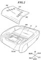
- a seat 10 shown in FIG. 1 is placed in a vehicle such as an automobile and the seat 10 is where a passenger such as a driver sits.
- the seat 10 includes a seat cushion 11 which supports the buttocks and thighs of the passenger, a seat back 14 which becomes a backrest, the lower end section thereof being supported by the seat cushion 11, and a headrest 16 which is provided on the seat back 14 and which supports the head of the passenger.
- auxiliary supporting units such as a neck-rest, armrests, footrests, an ottoman and the like can be included in addition.
- the seat cushion 11 mainly includes a seat cushion frame 17 (see the after-mentioned FIG. 3 ) which is the bone structure, a cushion pad 12 which is disposed on the seat cushion frame 17, and an outer cover 13 (omitted in FIG. 2 , see FIG. 1 ) which forms the outer surface of the seat by covering the seat cushion frame 17 and the cushion pad 12.
- an air passage 30 for air is formed in the seat cushion 11 between the cushion pad 12 and the outer cover 13.
- the air passage 30 is not mandatory.
- a concave for air passage 30A which forms a part of the air passage 30 is formed in the cushion pad 12. Further, a concave (not shown) which forms the rest of the air passage 30 is formed in the cover member 12A at the position corresponding to the concave for air passage 30A, and the air passage 30 is formed by fitting the cover member 12A in a predetermined section of the cushion pad 12.
- a plurality of punching holes are formed in the cover member 12A, and these punching holes are the air vents 30C of the air passage 30. Furthermore, the cushion pad 12 including the cover member 12A is covered with the outer cover 13, at least the section of the outer cover 13 corresponding to the air vents 30C being air permeable.
- the air taken in from the blower (not shown) is sent inside the air passage 30 via the through hole 30B, and the air flowed through the air passage 30 is blown out toward the passenger from the air vents 30C of the air passage 30.
- the seat cushion 11 of the embodiment includes the seat cushion frame 17 under the cushion pad 12.
- the seat cushion frame 17 mainly includes side frames 17A which form a left and right pair, connecting members 17B which connect the front end sections and the rear end sections of the side frames 17A (the connecting member 17B for the front end side is disposed under the pan frame 18), and the pan frame 18 which bridges across the side frames 17A and the connecting members 17B.
- the pan frame 18 functions as a board-like member which is disposed under the cushion pad 12 .
- the board-like member is configured in a different form other than the pan frame 18 will be described later as a modification example.
- the pan frame 18 (board-like member) has a concave 20 formed in the upper surface thereof, and the sensor 1 is disposed inside the concave 20.
- the sensor 1 can be a position sensor which can detect whether a passenger is seated in the seat 10.
- the sensor 1 can be directly attached in the concave 20. However, in the embodiment, the sensor 1 is fixed to an attachment bracket 2 and then, the attachment bracket 2 to which the sensor 1 is fixed is disposed inside the concave 20.
- the sensor 1 placed in the concave 20 needs to be fixated by screwing it thereto and this process can be difficult.
- the sensor 1 can be easily fixed to the attachment bracket 2 and the attachment bracket 2 can also be easily attached in the concave 20. Therefore, the sensor 1 can be easily disposed in the concave 20.
- the cushion pad 12 is disposed on the sensor 1. Then, when a passenger sits in the seat 10, the load of the passenger is applied to the sensor 1 via the cushion pad 12. At this time, if the sensor 1 is directly attached in the concave 20 of the pan frame 18, the entire load will be applied to the sensor 1 and the sensor 1 may be influenced in a bad way. However, if the sensor 1 is attached in the concave 20 via the attachment bracket 2 as described above, a part of the load of the passenger will be absorbed by the attachment bracket 2 when the load of the passenger is applied to the sensor 1. Therefore, comparing to the case where the sensor 1 is directly attached in the concave 20, the influence of the load of the passenger on the sensor 1 is reduced.
- FIG. 4 is a schematic view illustrating the sensor 1 and the attachment bracket 2
- FIG. 5 is an enlarged view illustrating the concave 20 and the like formed in the pan frame 18 (board-like member).
- engaging holes 2b with which the engaging units 1a of the sensor 1 engage are formed and holes 2c in which the screw units 1b (not shown in FIG. 4 , see the after-mentioned FIG. 7 ) of the sensor 1 are to be inserted are formed.
- a harness 1A which electrically connects the sensor 1 and external devices (not shown in the drawing, a power device, a device which processes the signals from the sensor 1 and the like) is connected to the sensor 1, and the attachment bracket 2 includes a guide unit 2d for the harness 1A. Since the guide unit 2d gradually inclines downward with respect to the main body unit 2a of the attachment bracket 2, the harness 1A is guided by the guide unit 2d to be in a state where it gradually inclines downward.
- the harness 1A will hang down by its own weight at the part where the harness 1A and the sensor 1 are connected. In such state, when the seat 10 shakes along with the vehicle shaking, the harness 1A will shake relatively in a large movement with respect to the sensor 1. Therefore, the harness 1A can be easily damaged or can be easily cut off.
- the harness 1A by supporting the harness 1A by the guide unit 2d of the attachment bracket 2 as described above, the harness 1A being in the state where it gradually inclines downward, the harness 1A which is supported by the guide unit 2d will not easily shake relatively with respect to the sensor 1 even when the seat 10 shakes. Therefore, the harness 1A will not be easily damaged nor easily cut off.
- the main body unit 2a of the attachment bracket 2 has cutouts 2e formed at the outer circumference section thereof.
- the attachment bracket 2 having the cutouts 2e at the outer circumference thereof, even in the case where the sensor 1 and the attachment bracket 2 are in the state of receiving the load as described above and a force which can deform the main body unit 2a of the attachment bracket 2 is applied thereto, the cutouts 2e absorb the deformation of the main body unit 2a of the attachment bracket 2. Therefore, the deformation of the main body unit 2a of the attachment bracket 2 can easily return to the original state when the force is not applied to the attachment bracket 2 any more, and the attachment bracket 2 will not remain to be in the deformed state.
- the concave 20 of the pan frame 18 has an engaging unit for attaching the attachment bracket 2 in the concave 20 by engaging with the attachment bracket 2 formed thereto.
- nail units 20a are formed as the engaging unit on the upper surface of the concave 20 so as to protrude, the nail units 20a being formed in the shape of nail.
- the main body unit 2a of the attachment bracket 2 has engaging holes 2f which engage with the nail units 20a formed therein.
- the attachment bracket 2 can be easily attached in the concave 20 in the embodiment since the attachment bracket 2 can be attached in the concave 20 just by making the attachment bracket 2 (engaging holes 2f) engage with the engaging unit (nail units 20a) formed in the concave 20.
- the attachment bracket 2 being attached in the concave 20 in the state where the nail units 20a of the concave 20 and the engaging holes 2f of the attachment bracket 2 engaging with each other, mainly the positioning of the attachment bracket 2 in the front and rear directions can be carried out accurately due to the nail units 20a. Furthermore, the nail units 20a can contribute to the positioning of the attachment bracket 2 in the right and left directions. Moreover, when the attachment bracket 2 is to be attached to the concave 20, by confirming that the nail units 20a protrude upward from the engaging holes 2f of the attachment bracket 2, whether the engaging holes 2f of the attachment bracket 2 and the nail units 20a are engaged with each other in an appropriate way and whether the attachment bracket 2 is disposed at an appropriate position in the concave can be confirmed.
- the case where the sensor 1 is disposed in the concave 20 in the state where the harness 1A extends to the left side of the sensor 1 is shown in FIGS. 3 to 5 .
- the sensor 1 is disposed in the concave 20 in the state where the harness 1A extends to the right side of the sensor 1.
- the nail units 20a are only formed in the rear side section of the concave 20 in the embodiment as shown in FIG. 5 .
- the engaging holes 2f of the attachment bracket 2 are formed not only in the rear side section but also in the front side section as in the state shown in FIG. 4 .
- the second engaging units 20b are formed near the nail units 20a on the upper surface of the concave 20.
- the edge sections ⁇ of the engaging holes 2f of the attachment bracket 2 are fit in between the nail units 20a and the second engaging units 20b.
- the positioning of the attachment bracket 2 in the front and rear directions can be carried out more accurately due to the edge sections ⁇ of the engaging holes 2f of the attachment bracket 2 being fit in between the nail units 20a and the second engaging units 20b of the concave 20. Further, the attachment bracket 2 will not be easily displaced in the front and rear directions.
- the left and right edge sections of the concave 20 are formed so as to be slightly higher than the upper surface of the concave 20 as shown in FIG. 5 , and these sections are the ribs 20c which respectively support the both edge sections (in the embodiment, the left and right sections) of the main body unit 2a of the attachment bracket 2 (see FIG. 6 ).
- the part of the main body unit 2a of the attachment bracket 2 other than the parts supported by the ribs 20c will be slightly in the air, floating above the upper surface of the concave 20. Therefore, as described above, the attachment bracket 2 can readily absorb a part of the load when the load of the passenger is applied to the sensor 1. Moreover, since the rigidity of the concave 20 itself can be improved by having the ribs 20c comparing to the case without the ribs 20c, the concave 20 will not break easily when a passenger sits in the seat 1 and the load of the passenger is applied to the pan frame 18, bending the pan frame 18.
- the rigidity of the concave 20 can be improved by further forming a rib on the under surface of the concave 20.
- escape units 20d are formed in the concave 20 as openings, and the escape units 20d are formed so that the engagement units 1a, the screw units 1b and the like of the sensor 1 which protrude downward from the under surface of the attachment bracket 2 can be positioned in the escape units 20d as shown in FIG. 7 when the attachment bracket 2 is attached to the concave 20.
- the engagement units 1a, the screw units 1b and the like of the sensor 1 which protrude downward from the under surface of the attachment bracket 2 will not interfere with the concave 20 when the attachment bracket 2 is attached in the concave 20.
- the attachment bracket 2 also has a structure for engaging with the concave 20 of the pan frame 18.
- the attachment bracket 2 includes bent units 2g which are respectively bent downward at the left and right edge sections of the main body unit 2a as shown in FIG. 4 .
- the left side bent unit 2g of the attachment bracket 2 is divided in two, one in the front side and the other in the rear side, because the guide unit 2d is formed between the two divided parts of the bent unit 2g, and the right side bent unit 2g of the attachment bracket 2 is formed as one plate-like unit (see FIG. 7 and the after-mentioned FIG. 9 ).
- the ribs 20c of the concave 20 will be tightly fit between the bent units 2g (see FIG. 5 ) on the left and right sides. In such way, mainly the positioning of the attachment bracket 2 can be carried out accurately due to the bent units 2g, and the attachment bracket 2 will not be easily displaced in the left and right directions. Further, by bending the attachment bracket 2 to form the bent units 2g, the rigidity of the attachment bracket 2 itself can be improved.
- bent units 2g of the attachment bracket 2 have bracket-side engaging units 2h formed thereto so as to protrude in the front direction from the front end sections of the bent units 2g and protrude in the rear direction from the rear end sections of the bent units 2g.
- the sensor 1 can be accurately and firmly attached in the concave 20 of the pan frame 18 via the attachment bracket 2 as shown in FIG. 8 .
- the harness 1A can be guided so as to go under the seat 10 by inserting the harness 1A in an opening 18A.
- the opening 18A for inserting the harness 1A can be newly formed in the pan frame 18.
- the present invention is not limited to the case where two openings 18A are formed as shown in FIG. 3 and other drawings, and there may be one opening 18A or there may be three or more openings 18A.
- the openings 18A there is no need to form the openings 18A on the left and right sides of the concave 20 as shown in FIG. 3 and other drawings and the openings 18A may be formed on the front and rear sides or the like of the concave 20. Furthermore, the openings 18A may be cutouts (that is, formed in the shapes that are cut out inward from the end sections of the pan frame 18), and the openings 18A are not limited to the holes as shown in FIG. 3 and other drawings. Further, the openings 18A do not need to be the opening for the duct 19 which will be described hereinafter.
- the air passage 30 is formed between the cushion pad 12 and the outer cover 13 of the seat cushion 11.
- the air sent in from the blower (not shown) which is provided under the pan frame 18 is sent into the air passage 30 through the through hole 30B, and the air flowed through the air passage 30 is blown out toward the passenger from the air vents 30C of the air passage 30.
- an opening 18A is formed as a through hole in which a duct 19 (see FIG. 1 ) for supplying the air to the through hole 30B from the blower can be inserted.
- the opening 18A for duct which is already formed can be utilized without newly forming an opening 18A in the pan frame 18 and the harness 1A can be inserted in the opening 18A.
- the blower is provided under the pan frame 18 and usually, is provided either on the left or right side of the seat 10. Therefore, the position in the pan frame 18 where the duct 19 penetrates is also more to the left or right with respect to the center corresponding to the position of the blower.
- a total of two openings 18A in which the duct 19 can be inserted are formed, one on the left side and the other on the right side with respect to the center of the pan frame 18 as shown in FIGS. 3 and 5 so as to accommodate both cases.
- the section between the two openings 18A is a concave and the above described concave 20 of the pan frame 18 is formed in this section.
- the openings 18A are formed continuously from the concave 20 of the pan frame 18 in such way. That is, the above described concave 20 in which the sensor 1 and the attachment bracket 2 are to be disposed is formed at the section between the plurality of openings 18A which are formed near each other (the section between the plurality of openings 18A that bridges across the front section and the rear section of the pan frame 18).
- the rigidity of the section between them becomes weak and the section can easily deform.
- the rigidity of the concave 20 itself is improved by having the ribs 20C formed in the concave 20 which is formed in this section as described above, such deformation will not occur easily.
- the harness 1A of the sensor 1 which is attached in the concave 20 of the pan frame 18 via the attachment bracket 2 is inserted in an opening 18A which is formed continuously from the concave 20, the harness 1A can be easily routed compared to the case where there is a distance between the concave 20 and the opening 18A. Furthermore, if there is a distance between the concave 20 and the opening 18A, the harness 1A will be sandwiched between the pan frame 18 and the cushion pad 12 (see FIG. 2 and the after-mentioned FIG. 10 ) and there is a possibility that the harness 1A is damaged due to the harness 1A and the pan frame 18 or the harness 1A and the cushion pad 12 rubbing against each other. However, if the concave 20 and the opening 18A are formed continuously as in the embodiment, the rubbing as described above will not easily occur and the harness 1A will not be easily damaged nor cut off.
- the duct 19 will be inserted in any one opening 18A of the plurality of openings 18A as shown in FIG. 3 . Therefore, by inserting the harness 1A in the opening 18A in which the duct 19 is not inserted, the harness 1A and the duct 19 will not interfere with each other and the harness 1A and the duct 19 will not rub against each other. Thus, the harness 1A will not be easily damaged nor cut off.
- the configuration may be such that the harness 1A is inserted in the opening 18A in which the duct 19 is inserted.
- the duct 19 is inserted in the opening 18A of the pan frame 18 and is inserted in the through hole 30B which is formed in the cushion pad 12 from below as shown in FIG. 10 . Since the cushion pad 12 will not be raised due to the duct 19 being inserted in the through hole 30B, the state where the upper surface of the sensor 1 abutting the under surface of the cushion pad 12 will be maintained.
- the sensor 1 can reliably detect the load when a passenger sits in the seat 10.
- FIG. 10 there is shown a configuration where the upper surface of the pan frame 18 and the upper surface of the sensor 1 are in flash and where the cushion pad 12 whose bottom is flat is place on the pan frame 18 and the sensor 1.
- the configuration may be such that the sensor 1 is disposed so that the upper surface of the sensor 1 be higher than the upper surface of the pan frame 18 and that a concave is formed in the section of the cushion pad 12 corresponding to the sensor 1.
- the concave 20 of the pan frame 18 is formed at the position right under a hollow section such as the air passage 30 or the like formed in the cushion pad 12 as shown in FIG. 11 , the section of the cushion pad 12 above the hollow section will deform downward and absorbs the load when a passenger sits in the seat 10, and the load will not be fully transmitted to the section below the hollow section. Therefore, the pressure applied to the sensor 1 will not increase sufficiently and it may be difficult to detect that a passenger has sat in the seat 10 by the sensor 1.
- the concave 20 in which the sensor 1 is disposed is formed at a position other than the position right below the hollow section such as the air passage 30 or the like which is formed in the cushion pad 12.
- the sensor 1 is disposed in the concave 20 which is formed in the upper surface of the board-like member (pan frame 18) which is disposed under the cushion pad 12 (see FIG. 10 ).
- the sensor 1 is disposed between the cushion pad 12 and the outer cover 13 (that is, just under the outer cover). Therefore, the passenger who sat in the seat 10 can feel something against their buttocks or thighs through the outer cover 13 of the seat 10 and the sitting comfort may be unpleasant.
- the cushion pad 12 is placed between the buttocks and thighs of the passenger and the sensor 1 as described above, the passenger who is sitting in the seat 10 will not feel the sensor 1 against their buttocks and thighs and the sitting comfort of the passenger can improve comparing to the traditional case.
- the cushion pad 12 will be raised for the height of the sensor 1, and this can cause discomfort in the passenger who is setting and the sitting comfort may be unpleasant.
- the concave 20 is formed in the upper surface of the board-like member (pan frame 18) and the sensor 1 is disposed therein as described above, such discomfort as described above can be avoided and the sitting comfort can be improved.
- the pan frame 18 which is disposed under the cushion pad 12 is used as the board-like member.
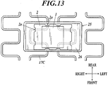
- the structure of the seat cushion frame 17 under the cushion pad 12 may include the pan frame 18 and the wires 17C (also called S springs or the like) as shown in FIG. 12 or may only include the wires 17C and not the pan frame 18.
- the board-like member can be set at the section where the wires 17C are disposed.
- the board-like member 25 can be set at the section where the wires 17C are disposed so that the wires 17C be inserted therein as shown in FIG. 13 .
- the concave 26 can be formed in the upper surface of the board-like member 25 and the sensor 1 can be disposed in the concave 26 in the state where it is fixated to the attachment bracket 2.
- the engaging units (see FIGS. 4 and 5 ) and the like for attaching the attachment bracket 2 in the concave 26 are not shown in FIG. 13
- the engaging units and the like are formed in both the concave 26 and the attachment bracket 2 as needed.
- the harness 1A and the like of the sensor 1 are also not shown
- the attachment bracket 2 can also include the guide unit 2d (see FIG. 4 ) and the like.
- the configuration of the concave 20, the attachment bracket 2 and the like according to the above described embodiment can be applied to the concave 26, the attachment bracket 2 and the like of the modification example as needed.
- the attachment bracket 2 and the parts raised by the wires 17C can be prevented from interfering with each other due to the attachment bracket 2 having the cutouts 2e formed at the parts corresponding to the parts raised by the wires 17C. Therefore, the attachment bracket 2, the board-like member 25 and the like can be prevented from being damaged and the like.
- the present invention can be applied to a vehicle seat.
Abstract
Description
- The present invention relates to a seat disposition structure in a seat.
- There is a case where a sensor such as a position sensor or the like which detects whether a passenger is seated in a seat is disposed in the seat (see Patent Document 1) .
- For example, such sensor is used to detect that a passenger is seated in the seat in the seatbelt reminder technique where the passenger is warned when he/she is not wearing the seatbelt although he/she is sitting in the seat.
- Patent Document 1:
JP 2014-100941A - Traditionally, when such sensor is to be disposed in a seat, there is a case where the sensor is to be disposed between the cushion pad and the outer cover of the seat cushion of the seat as described in
Patent Document 1, for example. - However, when a sensor is disposed between a cushion pad and an outer cover, that is, if a sensor is disposed right under an outer cover, the sitting comfort may be unpleasant since the passenger who sits in the seat feels something against his/her buttocks and thighs through the outer cover of the seat.
- The present invention is made in view of the above problem, and the object of the present invention is to provide a sensor disposition structure in a seat which improves sitting comfort of a passenger when disposing a sensor in a seat.
- In order to solve the problem, the invention according to
claim 1 is a sensor disposition structure in a seat, including: - a cushion pad; and
- a board-like member which is disposed under the cushion pad,
- wherein a concave is formed in an upper surface of the board-like member, and a sensor is disposed in the concave.
- The invention according to
claim 2 is the sensor disposition structure in the seat ofclaim 1, wherein the sensor is disposed in the concave while being fixed to an attachment bracket. - The invention according to claim 3 is the sensor disposition structure in the seat of
claim 2, wherein the attachment bracket is attached in the concave while being engaged with an engaging unit formed in the concave. - The invention according to claim 4 is the sensor disposition structure in the seat of claim 3, wherein a nail unit which is formed in a nail shape is formed on the upper surface of the concave as the engaging unit, the nail unit protruding from the upper surface of the concave.
- The invention according to claim 5 is the sensor disposition structure in the seat of claim 4, wherein a second engaging unit is formed on the upper surface of the concave at a position near the nail unit.
- The invention according to claim 6 is the sensor disposition structure in the seat of any one of
claims 2 to 5, wherein
an opening is formed in the board-like member,
the attachment bracket includes a bent unit which is bent at a position corresponding to the opening, and
the attachment bracket includes a bracket-side engaging unit which protrudes from an edge section of the bent unit and which engages with the under surface of the board-like member. - The invention according to claim 7 is the sensor disposition structure in the seat of any one of
claims 2 to 6, wherein the attachment bracket is attached in the concave by the bracket-side engaging unit engaging with an under surface of the board-like member and by the attachment bracket engaging with a nail unit which is formed on an upper surface of the concave so as to protrude therefrom. - The invention according to claim 8 is the sensor disposition structure in the seat of any one of
claims 2 to 7, wherein ribs which respectively supports both ends of the attachment bracket are provided on the upper surface of the concave. - The invention according to claim 9 is the sensor disposition structure in the seat of any one of
claims 2 to 8, wherein the attachment bracket includes a guide unit for a harness which electrically connects the sensor and an external device, and the guide unit inclines downward. - The invention according to
claim 10 is the sensor disposition structure in the seat of any one ofclaims 2 to 9, wherein the attachment bracket includes a cutout at an outer circumference section thereof. - The invention according to
claim 11 is the sensor disposition structure in the seat ofclaim 10, wherein the cutout is formed at a position corresponding to a section that is raised due to a wire being inserted in the board-like member. - The invention according to
claim 12 is the sensor disposition structure in the seat of any one ofclaims 1 to 11, wherein an opening is formed in the board-like member continuously from the concave, and a harness which electrically connects the sensor and an external device is inserted in the opening. - The invention according to
claim 13 is the sensor disposition structure in the seat ofclaim 12, wherein a duct for supplying air to an air passage which is formed in the cushion pad is inserted in the opening. - The invention according to
claim 14 is the sensor disposition structure in the seat ofclaim 13, wherein a plurality of openings are formed in the board-like member, and the harness is inserted in an opening in which the duct is not inserted. - The invention according to
claim 15 is the sensor disposition structure in the seat of any one ofclaims 1 to 14, wherein the concave in which the sensor is disposed is formed at a position avoiding a position right under a hollow section formed in the cushion pad. - According to the invention of
claim 1, a sensor disposition structure in a seat includes a cushion pad and a board-like member which is disposed under the cushion pad, wherein a concave is formed in an upper surface of the board-like member, and a sensor is disposed in the concave. The cushion pad is placed between the buttocks and thighs of the passenger and the sensor. This is different from the above-mentioned traditional case where the sensor is disposed between the cushion pad and the outer cover. The passenger sitting in the seat does not feel the sensor against their buttocks and thighs, and the sitting comfort of the passenger is improved as compared with the traditional case. - If the sensor is simply disposed on the upper surface of the board-like member, the cushion pad will be raised for the height of the sensor, and this can cause discomfort in the passenger who is setting and the sitting comfort may be unpleasant. However, according to the invention of
claim 1, since the sensor is disposed in the concave formed on the upper surface of the board-like member, the discomfort as described above is avoided and the sitting comfort is improved. - According to the invention of
claim 2, the sensor is disposed in the concave while being fixed to the attachment bracket. Therefore, the sensor can be easily disposed in the concave since the attachment bracket is attached in the concave after the sensor is fixed to the attachment bracket. Further, when the passenger sits in the seat and the load of the passenger is applied to the sensor via the cushion pad, a part of the load will be absorbed by the attachment bracket. Thus, comparing to the case where the sensor is directly attached in the concave, the influence of the load of the passenger on the sensor becomes small. - According to the invention of claim 3, the attachment bracket is attached in the concave while being engaged with the engaging unit formed in the concave. Therefore, the attachment bracket can be easily attached in the concave. In addition, the positioning of the attachment bracket can be carried out easily due to the engaging unit, and the attachment bracket will not be easily displaced in the front and rear directions, in the left and right directions and the like.
- According to the invention of claim 4, the nail unit which is formed in a nail shape is formed on the upper surface of the concave as the engaging unit. The nail unit protrudes from the upper surface of the concave. Therefore, mainly the positioning of the attachment bracket in the front and rear directions can be carried out accurately. Further, by confirming that the nail unit protrudes upward from the engaging hole of the attachment bracket when attaching the attachment bracket in the concave, whether the attachment bracket and the nail unit are engaged properly and whether the attachment bracket is disposed at the appropriate position in the concave can be easily confirmed.
- According to the invention of claim 5, the second engaging unit is formed on the upper surface of the concave at a position near the nail unit. Therefore, when attaching the attachment bracket in the concave, the edge section α of the engaging hole of the attachment bracket will be tightly fit between the nail unit and the second engaging unit. Thus, the positioning of the attachment bracket in the front and rear directions can be carried out more accurately and the attachment bracket will not be easily displaced in the front and rear directions.
- According to the invention of claim 6, an opening is formed in the the board-like member, the attachment bracket includes the bent unit which is bent at a position corresponding to the opening, and the attachment bracket includes the bracket-side engaging unit which protrudes from an edge section of the bent unit and which engages with the under surface of the board-like member. Therefore, mainly the positioning of the attachment bracket in the left and right directions can be carried out accurately due to the bent unit, and the attachment bracket will not be easily displaced in the left and right directions. In addition, the rigidity of the attachment bracket itself can be improved. Furthermore, since the attachment bracket includes the bracket-side engaging unit, mainly the positioning of the attachment bracket in the up and down directions can be carried out accurately due to the bracket-side engaging unit, and the attachment bracket will not be easily displaced in the up and down directions.
- According to the invention of claim 7, the attachment bracket is attached in the concave by the bracket-side engaging unit engaging with the under surface of the board-like member and by the attachment bracket engaging with the nail unit which is formed on the upper surface of the concave so as to protrude therefrom. Therefore, the positioning of the attachment bracket can be carried out more accurately and the attachment bracket will not be easily displaced in the front and rear directions, the up and down directions and the like.
- According to the invention of claim 8, ribs which respectively support the both end sections of the attachment bracket are formed on the upper surface of the concave. Therefore, since the main body unit of the attachment bracket will be in a state slightly floating in the concave with respect to the part other than the rib parts, the attachment bracket can readily absorb a part of the load when the load of the passenger is applied to the sensor. Further, since the rigidity of the concave itself can be improved by having the ribs, the concave will not be easily damaged.
- According to the invention of claim 9, the attachment bracket includes the guide unit for the harness which electrically connects the sensor and an external device, and the guide unit inclines downward. Therefore, the harness will be supported by the guide unit from below in the state where the harness gradually inclines downward by being guided by the guide unit. Thus, the harness which is supported by the guide unit will not easily shake with respect to the sensor even when the seat shakes, and the harness will not be easily damaged nor cut off.
- According to the invention of
claim 10, the attachment bracket includes the cutout at an outer circumference section thereof. Therefore, even in the case where the load is applied to the sensor and the attachment bracket and the force that can deform the attachment bracket is applied, the cutout will absorb the deformation of the attachment bracket. Thus, the deformation of the attachment bracket can easily return to the original state when the force is not applied to the attachment bracket any more, and the attachment bracket will not remain to be in the deformed state. - According to the invention of
claim 11, the cutout is formed at a position corresponding to a section that is raised due to a wire being inserted in the board-like member. Therefore, the attachment bracket and the parts raised by the wires can be prevented from interfering with each other. Thus, the attachment bracket, the board-like member and the like can be prevented from being damaged and the like. - According to the invention of
claim 12, the opening is formed in the board-like member continuously from the concave, and the harness which electrically connects the sensor and an external device is inserted in the opening. Therefore, the harness can be easily routed comparing to the case where there is a distance between the concave and the opening. In addition, if there is a distance between the concave and the opening, the harness will be placed between the board-like member and the cushion pad, and there is a possibility that the harness will be damaged or cut off due to the harness rubbing against the board-like member and the cushion pad. However, if the concave and the opening are formed continuously, such rubbing against each other will not easily occur and the harness will not be easily damaged nor cut off. - According to the invention of
claim 13, the duct for supplying air to the air passage which is formed in the cushion pad can be inserted in the opening. Therefore, the opening for the duct which is already formed can be utilized and the harness can be inserted in the opening without forming a new opening in the board-like member. - According to the invention of
claim 14, a plurality of openings are formed in the board-like member, and the harness is inserted in the opening in which the duct is not inserted. Therefore, the harness and the duct do not interfere with each other and the harness and the duct do not rub against each other. Thus, the harness will not be easily damaged nor cut off. - According to the invention of
claim 15, the concave in which the sensor is disposed is formed at a position avoiding a position right under the hollow section formed in the cushion pad. Therefore, the load which is applied to the cushion pad when the passenger sits in the seat is directly applied to the sensor without being absorbed by the hollow section formed in the cushion pad. Thus, the pressure applied to the sensor can be increased accurately, and it will be easy to detect that the passenger has sat in the seat by the sensor. -
-
FIG. 1 is a schematic view illustrating a seat. -
FIG. 2 is a schematic view illustrating an air passage and the like which are formed in a cushion pad of a seat cushion. -
FIG. 3 is a schematic view illustrating a seat cushion frame and a sensor and the like which are disposed in a concave of a pan frame (board-like member). -
FIG. 4 is a schematic view illustrating a sensor and an attachment bracket. -
FIG. 5 is an enlarged view illustrating the concave and the like which are formed in the pan frame (board-like member). -
FIG. 6 is a schematic view illustrating a state where the attachment bracket is attached in the concave. -
FIG. 7 is a schematic view illustrating a state where the state shown inFIG. 8 is seen from the back side of the pan frame (board-like member). -
FIG. 8 is a schematic view illustrating a state where the attachment bracket to which the sensor and the like are attached is attached in the concave. -
FIG. 9 is a view illustrating a state where a bracket-side engaging unit which is formed at the bent unit of the attachment bracket is engaged with the lower surface side of the pan frame (board-like member). -
FIG. 10 is a cross-sectional view illustrating a state where the sensor which is disposed in the concave of the pan frame (board-like member) abuts the lower surface of the cushion pad. -
FIG. 11 is a cross-sectional view illustrating a state where the sensor is disposed at the position that is directly under the hollow section formed in the cushion pad. -
FIG. 12 is a schematic view illustrating an example of a seat cushion frame provided with a wire. -
FIG. 13 is a view illustrating a modification example of the board-like member or the like which is set so as to have a wire inserted therein. - Hereinafter, embodiments of the present invention will be described with reference to the drawings. However, although various technically preferred limitations for implementing the present invention are included in the following embodiments, the technical scope of the present invention is not limited to the following embodiments and the examples shown in the drawings in any way.
- A
seat 10 shown inFIG. 1 is placed in a vehicle such as an automobile and theseat 10 is where a passenger such as a driver sits. As shown inFIG. 1 , theseat 10 includes aseat cushion 11 which supports the buttocks and thighs of the passenger, a seat back 14 which becomes a backrest, the lower end section thereof being supported by theseat cushion 11, and aheadrest 16 which is provided on the seat back 14 and which supports the head of the passenger. Here, auxiliary supporting units such as a neck-rest, armrests, footrests, an ottoman and the like can be included in addition. - As shown in
FIG. 2 , theseat cushion 11 mainly includes a seat cushion frame 17 (see the after-mentionedFIG. 3 ) which is the bone structure, acushion pad 12 which is disposed on theseat cushion frame 17, and an outer cover 13 (omitted inFIG. 2 , seeFIG. 1 ) which forms the outer surface of the seat by covering theseat cushion frame 17 and thecushion pad 12. - In the embodiment, an
air passage 30 for air (hot air and cold air) is formed in theseat cushion 11 between thecushion pad 12 and theouter cover 13. However, theair passage 30 is not mandatory. - In particular, as shown in
FIG. 2 , a concave for air passage 30A which forms a part of theair passage 30 is formed in thecushion pad 12. Further, a concave (not shown) which forms the rest of theair passage 30 is formed in thecover member 12A at the position corresponding to the concave for air passage 30A, and theair passage 30 is formed by fitting thecover member 12A in a predetermined section of thecushion pad 12. - Further, a plurality of punching holes are formed in the
cover member 12A, and these punching holes are theair vents 30C of theair passage 30. Furthermore, thecushion pad 12 including thecover member 12A is covered with theouter cover 13, at least the section of theouter cover 13 corresponding to theair vents 30C being air permeable. - The air taken in from the blower (not shown) is sent inside the
air passage 30 via the throughhole 30B, and the air flowed through theair passage 30 is blown out toward the passenger from theair vents 30C of theair passage 30. - The
seat cushion 11 of the embodiment includes theseat cushion frame 17 under thecushion pad 12. As shown inFIG. 3 , theseat cushion frame 17 mainly includes side frames 17A which form a left and right pair, connectingmembers 17B which connect the front end sections and the rear end sections of the side frames 17A (the connectingmember 17B for the front end side is disposed under the pan frame 18), and thepan frame 18 which bridges across the side frames 17A and the connectingmembers 17B. - Here, in the embodiment, a case where the
pan frame 18 functions as a board-like member which is disposed under thecushion pad 12 is described. However, a case where the board-like member is configured in a different form other than thepan frame 18 will be described later as a modification example. - The pan frame 18 (board-like member) has a concave 20 formed in the upper surface thereof, and the
sensor 1 is disposed inside the concave 20. For example, thesensor 1 can be a position sensor which can detect whether a passenger is seated in theseat 10. - The
sensor 1 can be directly attached in the concave 20. However, in the embodiment, thesensor 1 is fixed to anattachment bracket 2 and then, theattachment bracket 2 to which thesensor 1 is fixed is disposed inside the concave 20. - In the case where the
sensor 1 is directly attached in the concave 20 of thepan frame 18, thesensor 1 placed in the concave 20 needs to be fixated by screwing it thereto and this process can be difficult. However, as described above, by having the configuration where thesensor 1 is fixed to theattachment bracket 2 and then theattachment bracket 2 is attached in the concave 20, thesensor 1 can be easily fixed to theattachment bracket 2 and theattachment bracket 2 can also be easily attached in the concave 20. Therefore, thesensor 1 can be easily disposed in the concave 20. - Further, in the state where the
seat 10 is assembled, thecushion pad 12 is disposed on thesensor 1. Then, when a passenger sits in theseat 10, the load of the passenger is applied to thesensor 1 via thecushion pad 12. At this time, if thesensor 1 is directly attached in the concave 20 of thepan frame 18, the entire load will be applied to thesensor 1 and thesensor 1 may be influenced in a bad way. However, if thesensor 1 is attached in the concave 20 via theattachment bracket 2 as described above, a part of the load of the passenger will be absorbed by theattachment bracket 2 when the load of the passenger is applied to thesensor 1. Therefore, comparing to the case where thesensor 1 is directly attached in the concave 20, the influence of the load of the passenger on thesensor 1 is reduced. - Hereinafter, the configuration and the like of the concave 20 and the
attachment bracket 2 will be described in detail.FIG. 4 is a schematic view illustrating thesensor 1 and theattachment bracket 2, andFIG. 5 is an enlarged view illustrating the concave 20 and the like formed in the pan frame 18 (board-like member). - In the plate-like
main body unit 2a of theattachment bracket 2, engagingholes 2b with which the engagingunits 1a of thesensor 1 engage are formed andholes 2c in which the screw units 1b (not shown inFIG. 4 , see the after-mentionedFIG. 7 ) of thesensor 1 are to be inserted are formed. By inserting the engagingunits 1a of thesensor 1 in the engagingholes 2b of theattachment bracket 2 and the engagingunits 1a respectively engaging with the engagingholes 2b, and in this state, by further screwing on the screw units 1b which are inserted in theholes 2c of theattachment bracket 2 from the back side (that is, the lower side) of theattachment bracket 2, thesensor 1 can be easily attached to theattachment bracket 2. - A
harness 1A which electrically connects thesensor 1 and external devices (not shown in the drawing, a power device, a device which processes the signals from thesensor 1 and the like) is connected to thesensor 1, and theattachment bracket 2 includes aguide unit 2d for theharness 1A. Since theguide unit 2d gradually inclines downward with respect to themain body unit 2a of theattachment bracket 2, theharness 1A is guided by theguide unit 2d to be in a state where it gradually inclines downward. - If the
attachment bracket 2 does not have theguide unit 2d, theharness 1A will hang down by its own weight at the part where theharness 1A and thesensor 1 are connected. In such state, when theseat 10 shakes along with the vehicle shaking, theharness 1A will shake relatively in a large movement with respect to thesensor 1. Therefore, theharness 1A can be easily damaged or can be easily cut off. With respect to the above, by supporting theharness 1A by theguide unit 2d of theattachment bracket 2 as described above, theharness 1A being in the state where it gradually inclines downward, theharness 1A which is supported by theguide unit 2d will not easily shake relatively with respect to thesensor 1 even when theseat 10 shakes. Therefore, theharness 1A will not be easily damaged nor easily cut off. - Further, the
main body unit 2a of theattachment bracket 2 hascutouts 2e formed at the outer circumference section thereof. - Due to the
attachment bracket 2 having thecutouts 2e at the outer circumference thereof, even in the case where thesensor 1 and theattachment bracket 2 are in the state of receiving the load as described above and a force which can deform themain body unit 2a of theattachment bracket 2 is applied thereto, thecutouts 2e absorb the deformation of themain body unit 2a of theattachment bracket 2. Therefore, the deformation of themain body unit 2a of theattachment bracket 2 can easily return to the original state when the force is not applied to theattachment bracket 2 any more, and theattachment bracket 2 will not remain to be in the deformed state. - On the other hand, the concave 20 of the
pan frame 18 has an engaging unit for attaching theattachment bracket 2 in the concave 20 by engaging with theattachment bracket 2 formed thereto. - In particular, as shown in
FIG. 5 ,nail units 20a are formed as the engaging unit on the upper surface of the concave 20 so as to protrude, thenail units 20a being formed in the shape of nail. Further, themain body unit 2a of theattachment bracket 2 has engagingholes 2f which engage with thenail units 20a formed therein. When theattachment bracket 2 to which thesensor 1 is attached is to be attached in the concave 20, as shown inFIG. 6 , thenail units 20a of the concave 20 and the engagingholes 2f of theattachment bracket 2 will engage with each other. Here, inFIG. 6 , thesensor 1 and theharness 1A are omitted so that the engagement of thenails 20a and the engagingholes 2f can be seen clearly. - As described above, although this can also be said for the after-mentioned second engaging
units 20b and the like, theattachment bracket 2 can be easily attached in the concave 20 in the embodiment since theattachment bracket 2 can be attached in the concave 20 just by making the attachment bracket 2 (engagingholes 2f) engage with the engaging unit (nail units 20a) formed in the concave 20. - Further, due to the
attachment bracket 2 being attached in the concave 20 in the state where thenail units 20a of the concave 20 and the engagingholes 2f of theattachment bracket 2 engaging with each other, mainly the positioning of theattachment bracket 2 in the front and rear directions can be carried out accurately due to thenail units 20a. Furthermore, thenail units 20a can contribute to the positioning of theattachment bracket 2 in the right and left directions. Moreover, when theattachment bracket 2 is to be attached to the concave 20, by confirming that thenail units 20a protrude upward from the engagingholes 2f of theattachment bracket 2, whether the engagingholes 2f of theattachment bracket 2 and thenail units 20a are engaged with each other in an appropriate way and whether theattachment bracket 2 is disposed at an appropriate position in the concave can be confirmed. - Here, the case where the
sensor 1 is disposed in the concave 20 in the state where theharness 1A extends to the left side of thesensor 1 is shown inFIGS. 3 to 5 . However, there may be a case where thesensor 1 is disposed in the concave 20 in the state where theharness 1A extends to the right side of thesensor 1. Further, thenail units 20a are only formed in the rear side section of the concave 20 in the embodiment as shown inFIG. 5 . However, since the direction of theharness 1A, that is the direction of theguide unit 2d, may be in the left direction or in the right direction, therefore, the engagingholes 2f of theattachment bracket 2 are formed not only in the rear side section but also in the front side section as in the state shown inFIG. 4 . - Further, as shown in
FIG. 5 , the secondengaging units 20b are formed near thenail units 20a on the upper surface of the concave 20. When theattachment bracket 2 is attached in the concave 20, as shown inFIG. 6 , the edge sections α of the engagingholes 2f of theattachment bracket 2 are fit in between thenail units 20a and the secondengaging units 20b. - In such way, when the
attachment bracket 2 to which thesensor 1 is attached is attached in the concave 20 of thepan frame 18, the positioning of theattachment bracket 2 in the front and rear directions can be carried out more accurately due to the edge sections α of the engagingholes 2f of theattachment bracket 2 being fit in between thenail units 20a and the secondengaging units 20b of the concave 20. Further, theattachment bracket 2 will not be easily displaced in the front and rear directions. - Furthermore, in the embodiment, the left and right edge sections of the concave 20 are formed so as to be slightly higher than the upper surface of the concave 20 as shown in
FIG. 5 , and these sections are theribs 20c which respectively support the both edge sections (in the embodiment, the left and right sections) of themain body unit 2a of the attachment bracket 2 (seeFIG. 6 ). - By having the
ribs 20c in the way as described above, the part of themain body unit 2a of theattachment bracket 2 other than the parts supported by theribs 20c will be slightly in the air, floating above the upper surface of the concave 20. Therefore, as described above, theattachment bracket 2 can readily absorb a part of the load when the load of the passenger is applied to thesensor 1. Moreover, since the rigidity of the concave 20 itself can be improved by having theribs 20c comparing to the case without theribs 20c, the concave 20 will not break easily when a passenger sits in theseat 1 and the load of the passenger is applied to thepan frame 18, bending thepan frame 18. - Here, for example, the rigidity of the concave 20 can be improved by further forming a rib on the under surface of the concave 20.
- Further,
escape units 20d are formed in the concave 20 as openings, and theescape units 20d are formed so that theengagement units 1a, the screw units 1b and the like of thesensor 1 which protrude downward from the under surface of theattachment bracket 2 can be positioned in theescape units 20d as shown inFIG. 7 when theattachment bracket 2 is attached to the concave 20. In the embodiment, by having such configuration, theengagement units 1a, the screw units 1b and the like of thesensor 1 which protrude downward from the under surface of theattachment bracket 2 will not interfere with the concave 20 when theattachment bracket 2 is attached in the concave 20. - In the embodiment, the
attachment bracket 2 also has a structure for engaging with the concave 20 of thepan frame 18. In particular, theattachment bracket 2 includesbent units 2g which are respectively bent downward at the left and right edge sections of themain body unit 2a as shown inFIG. 4 . Here, in the state shown inFIG. 4 , the left sidebent unit 2g of theattachment bracket 2 is divided in two, one in the front side and the other in the rear side, because theguide unit 2d is formed between the two divided parts of thebent unit 2g, and the right sidebent unit 2g of theattachment bracket 2 is formed as one plate-like unit (seeFIG. 7 and the after-mentionedFIG. 9 ). - When the
attachment bracket 2 is to be attached in the concave 20, theribs 20c of the concave 20 will be tightly fit between thebent units 2g (seeFIG. 5 ) on the left and right sides. In such way, mainly the positioning of theattachment bracket 2 can be carried out accurately due to thebent units 2g, and theattachment bracket 2 will not be easily displaced in the left and right directions. Further, by bending theattachment bracket 2 to form thebent units 2g, the rigidity of theattachment bracket 2 itself can be improved. - Further, the
bent units 2g of theattachment bracket 2 have bracket-side engaging units 2h formed thereto so as to protrude in the front direction from the front end sections of thebent units 2g and protrude in the rear direction from the rear end sections of thebent units 2g. - Furthermore, as shown in
FIG. 9 , when theattachment bracket 2 is attached in the concave 20 of thepan frame 18, the bracket-side engaging units 2h of theattachment bracket 2 engage with the under surface of the pan frame 18 (see β inFIG. 9 , Rs in the drawing show the ribs formed on the under surface of the pan frame 18). By having such configuration, mainly the positioning of theattachment bracket 2 in the upward and downward directions can be carried out accurately due to the bracket-side engaging units 2h, and theattachment bracket 2 will not be easily displaced in the upward and downward directions. - In the embodiment, as described above, by attaching the
attachment bracket 2 to which thesensor 1 is attached in the concave 20 of thepan frame 18, thesensor 1 can be accurately and firmly attached in the concave 20 of thepan frame 18 via theattachment bracket 2 as shown inFIG. 8 . - On the other hand, in the case where the
openings 18A are formed in thepan frame 18 as shown inFIGS. 3 and5 , theharness 1A can be guided so as to go under theseat 10 by inserting theharness 1A in anopening 18A. - Here, the
opening 18A for inserting theharness 1A can be newly formed in thepan frame 18. Hereinafter, although a description will be given on the basis ofFIGS. 3 ,5 and other drawings, the present invention is not limited to the case where twoopenings 18A are formed as shown inFIG. 3 and other drawings, and there may be oneopening 18A or there may be three ormore openings 18A. - Further, there is no need to form the
openings 18A on the left and right sides of the concave 20 as shown inFIG. 3 and other drawings and theopenings 18A may be formed on the front and rear sides or the like of the concave 20. Furthermore, theopenings 18A may be cutouts (that is, formed in the shapes that are cut out inward from the end sections of the pan frame 18), and theopenings 18A are not limited to the holes as shown inFIG. 3 and other drawings. Further, theopenings 18A do not need to be the opening for theduct 19 which will be described hereinafter. - In the
seat 10 of the embodiment, as shown inFIG. 2 , theair passage 30 is formed between thecushion pad 12 and theouter cover 13 of theseat cushion 11. The air sent in from the blower (not shown) which is provided under thepan frame 18 is sent into theair passage 30 through the throughhole 30B, and the air flowed through theair passage 30 is blown out toward the passenger from theair vents 30C of theair passage 30. Further, anopening 18A is formed as a through hole in which a duct 19 (seeFIG. 1 ) for supplying the air to the throughhole 30B from the blower can be inserted. - Therefore, by using the
opening 18A as the opening for inserting theharness 1A of thesensor 1, theopening 18A for duct which is already formed can be utilized without newly forming anopening 18A in thepan frame 18 and theharness 1A can be inserted in theopening 18A. - Moreover, the blower is provided under the
pan frame 18 and usually, is provided either on the left or right side of theseat 10. Therefore, the position in thepan frame 18 where theduct 19 penetrates is also more to the left or right with respect to the center corresponding to the position of the blower. In view of this, in theseat 10 of the embodiment, a total of twoopenings 18A in which theduct 19 can be inserted are formed, one on the left side and the other on the right side with respect to the center of thepan frame 18 as shown inFIGS. 3 and5 so as to accommodate both cases. - Further, in the embodiment, the section between the two
openings 18A is a concave and the above described concave 20 of thepan frame 18 is formed in this section. - In the embodiment, the
openings 18A are formed continuously from the concave 20 of thepan frame 18 in such way. That is, the above described concave 20 in which thesensor 1 and theattachment bracket 2 are to be disposed is formed at the section between the plurality ofopenings 18A which are formed near each other (the section between the plurality ofopenings 18A that bridges across the front section and the rear section of the pan frame 18). - In general, if the plurality of
openings 18A are formed near each other, the rigidity of the section between them becomes weak and the section can easily deform. However, in the embodiment, since the rigidity of the concave 20 itself is improved by having the ribs 20C formed in the concave 20 which is formed in this section as described above, such deformation will not occur easily. - Further, since the
harness 1A of thesensor 1 which is attached in the concave 20 of thepan frame 18 via theattachment bracket 2 is inserted in anopening 18A which is formed continuously from the concave 20, theharness 1A can be easily routed compared to the case where there is a distance between the concave 20 and theopening 18A. Furthermore, if there is a distance between the concave 20 and theopening 18A, theharness 1A will be sandwiched between thepan frame 18 and the cushion pad 12 (seeFIG. 2 and the after-mentionedFIG. 10 ) and there is a possibility that theharness 1A is damaged due to theharness 1A and thepan frame 18 or theharness 1A and thecushion pad 12 rubbing against each other. However, if the concave 20 and theopening 18A are formed continuously as in the embodiment, the rubbing as described above will not easily occur and theharness 1A will not be easily damaged nor cut off. - Further, the
duct 19 will be inserted in any oneopening 18A of the plurality ofopenings 18A as shown inFIG. 3 . Therefore, by inserting theharness 1A in theopening 18A in which theduct 19 is not inserted, theharness 1A and theduct 19 will not interfere with each other and theharness 1A and theduct 19 will not rub against each other. Thus, theharness 1A will not be easily damaged nor cut off. - Here, the configuration may be such that the
harness 1A is inserted in theopening 18A in which theduct 19 is inserted. - In the embodiment, the
duct 19 is inserted in theopening 18A of thepan frame 18 and is inserted in the throughhole 30B which is formed in thecushion pad 12 from below as shown inFIG. 10 . Since thecushion pad 12 will not be raised due to theduct 19 being inserted in the throughhole 30B, the state where the upper surface of thesensor 1 abutting the under surface of thecushion pad 12 will be maintained. - Further, when a passenger sits in the
seat 10, the load is applied to thecushion pad 12 from above, thecushion pad 12 is compressed and the pressure applied to thesensor 1 from thecushion pad 12 increases. Therefore, thesensor 1 can reliably detect the load when a passenger sits in theseat 10. - Here, in
FIG. 10 , there is shown a configuration where the upper surface of thepan frame 18 and the upper surface of thesensor 1 are in flash and where thecushion pad 12 whose bottom is flat is place on thepan frame 18 and thesensor 1. However, the configuration may be such that thesensor 1 is disposed so that the upper surface of thesensor 1 be higher than the upper surface of thepan frame 18 and that a concave is formed in the section of thecushion pad 12 corresponding to thesensor 1. - Moreover, if the concave 20 of the
pan frame 18 is formed at the position right under a hollow section such as theair passage 30 or the like formed in thecushion pad 12 as shown inFIG. 11 , the section of thecushion pad 12 above the hollow section will deform downward and absorbs the load when a passenger sits in theseat 10, and the load will not be fully transmitted to the section below the hollow section. Therefore, the pressure applied to thesensor 1 will not increase sufficiently and it may be difficult to detect that a passenger has sat in theseat 10 by thesensor 1. - Therefore, it is preferred that the concave 20 in which the
sensor 1 is disposed is formed at a position other than the position right below the hollow section such as theair passage 30 or the like which is formed in thecushion pad 12. By having such configuration, the load applied to thecushion pad 12 will be directly applied to thesensor 1 when a passenger sits in theseat 10. Therefore, the pressure which is applied to thesensor 1 can increase appropriately and whether a passenger has sat in theseat 10 can be easily detected. - As described above, according to the disposition structure of the
sensor 1 in theseat 10 of the embodiment, thesensor 1 is disposed in the concave 20 which is formed in the upper surface of the board-like member (pan frame 18) which is disposed under the cushion pad 12 (seeFIG. 10 ). - In the traditional disposition structure of a sensor in a seat, as described above, the
sensor 1 is disposed between thecushion pad 12 and the outer cover 13 (that is, just under the outer cover). Therefore, the passenger who sat in theseat 10 can feel something against their buttocks or thighs through theouter cover 13 of theseat 10 and the sitting comfort may be unpleasant. - However, in the disposition structure of the
sensor 1 in theseat 10 according to the embodiment, since thecushion pad 12 is placed between the buttocks and thighs of the passenger and thesensor 1 as described above, the passenger who is sitting in theseat 10 will not feel thesensor 1 against their buttocks and thighs and the sitting comfort of the passenger can improve comparing to the traditional case. - Further, if the
sensor 1 is simply disposed on the upper surface of the board-like member (pan frame 18), thecushion pad 12 will be raised for the height of thesensor 1, and this can cause discomfort in the passenger who is setting and the sitting comfort may be unpleasant. However, according to the disposition structure of thesensor 1 in theseat 10 of the embodiment, since the concave 20 is formed in the upper surface of the board-like member (pan frame 18) and thesensor 1 is disposed therein as described above, such discomfort as described above can be avoided and the sitting comfort can be improved. - Here, in the above described embodiment, the case where the
pan frame 18 which is disposed under thecushion pad 12 is used as the board-like member is described. However, the structure of theseat cushion frame 17 under the cushion pad 12 (not shown inFIG. 12 ), for example, may include thepan frame 18 and thewires 17C (also called S springs or the like) as shown inFIG. 12 or may only include thewires 17C and not thepan frame 18. - In such case, the board-like member can be set at the section where the
wires 17C are disposed. - At that time, for example, the board-
like member 25 can be set at the section where thewires 17C are disposed so that thewires 17C be inserted therein as shown inFIG. 13 . Further, in the way similar to that in the above described embodiment, the concave 26 can be formed in the upper surface of the board-like member 25 and thesensor 1 can be disposed in the concave 26 in the state where it is fixated to theattachment bracket 2. - Here, although the engaging units (see
FIGS. 4 and5 ) and the like for attaching theattachment bracket 2 in the concave 26 are not shown inFIG. 13 , the engaging units and the like are formed in both the concave 26 and theattachment bracket 2 as needed. Although theharness 1A and the like of thesensor 1 are also not shown, theattachment bracket 2 can also include theguide unit 2d (seeFIG. 4 ) and the like. In addition, the configuration of the concave 20, theattachment bracket 2 and the like according to the above described embodiment can be applied to the concave 26, theattachment bracket 2 and the like of the modification example as needed. - In the case of the modification example shown in
FIG. 13 , since thewires 17C are inserted in the board-like member 25, the parts of the concave 26 of the board-like member 25 where thewires 17C are inserted are raised comparing to the other parts (see the dotted lines in the drawing). Therefore, thecutouts 2e (seeFIG. 4 ) of theattachment bracket 2 in the above described embodiment can be formed at the positions corresponding to the parts raised by thewires 17C which are inserted in the board-like member 25 as shown inFIG. 13 . - By having such configuration, in addition to the functions and effects described in the above embodiment, the
attachment bracket 2 and the parts raised by thewires 17C can be prevented from interfering with each other due to theattachment bracket 2 having thecutouts 2e formed at the parts corresponding to the parts raised by thewires 17C. Therefore, theattachment bracket 2, the board-like member 25 and the like can be prevented from being damaged and the like. - Here, it is needless to say that the present invention is not limited to the above described embodiment and modification example, and various modifications can be made as needed as long as they are within the scope of the invention.
- The present invention can be applied to a vehicle seat.
-
- 1
- sensor
- 1A
- harness
- 2
- attachment bracket
- 2d
- guide unit
- 2e
- cutout
- 2g
- bent unit
- 2h
- bracket-side engaging unit
- 10
- seat
- 12
- cushion pad
- 17C
- wire
- 18
- pan frame (board-like member)
- 18A
- opening
- 19
- duct
- 20
- concave
- 20a
- nail unit (engaging unit)
- 20b
- second engaging unit (engaging unit)
- 20c
- rib
- 25
- board-like member
- 26
- concave
- 30
- air passage (hollow section)
- β
- under surface of board-like member
Claims (15)
- A sensor disposition structure in a seat, comprising:a cushion pad; anda board-like member which is disposed under the cushion pad,whereina concave is formed in an upper surface of the board-like member, and a sensor is disposed in the concave.
- The sensor disposition structure in the seat of claim 1, wherein the sensor is disposed in the concave while being fixed to an attachment bracket.
- The sensor disposition structure in the seat of claim 2, wherein the attachment bracket is attached in the concave while being engaged with an engaging unit formed in the concave.
- The sensor disposition structure in the seat of claim 3, wherein a nail unit which is formed in a nail shape is formed on the upper surface of the concave as the engaging unit, the nail unit protruding from the upper surface of the concave.
- The sensor disposition structure in the seat of claim 4, wherein a second engaging unit is formed on the upper surface of the concave at a position near the nail unit.
- The sensor disposition structure in the seat of claim 2, wherein
an opening is formed in the board-like member,
the attachment bracket includes a bent unit which is bent at a position corresponding to the opening, and
the attachment bracket includes a bracket-side engaging unit which protrudes from an edge section of the bent unit and which engages with the under surface of the board-like member. - The sensor disposition structure in the seat of claim 2, wherein the attachment bracket is attached in the concave by a bracket-side engaging unit engaging with an under surface of the board-like member and by the attachment bracket engaging with a nail unit which is formed on an upper surface of the concave so as to protrude therefrom.
- The sensor disposition structure in the seat of claim 2, wherein ribs which respectively supports left and right sections of the attachment bracket are provided on the upper surface of the concave.
- The sensor disposition structure in the seat of claim 2, wherein the attachment bracket includes a guide unit for a harness which electrically connects the sensor and an external device, and the guide unit inclines downward.
- The sensor disposition structure in the seat of claim 2, wherein the attachment bracket includes a cutout at an outer circumference section thereof.
- The sensor disposition structure in the seat of claim 10, wherein the cutout is formed at a position corresponding to a section that is raised due to a wire being inserted in the board-like member.
- The sensor disposition structure in the seat of claim 1, wherein an opening is formed in the board-like member continuously from the concave, and a harness which electrically connects the sensor and an external device is inserted in the opening.
- The sensor disposition structure in the seat of claim 12, wherein a duct for supplying air to an air passage which is formed in the cushion pad is inserted in the opening.
- The sensor disposition structure in the seat of claim 13, wherein a plurality of openings are formed in the board-like member, and the harness is inserted in an opening in which the duct is not inserted.
- The sensor disposition structure in the seat of any one of claims 1 to 14, wherein the concave in which the sensor is disposed is formed at a position avoiding a position right under a hollow section formed in the cushion pad.
Priority Applications (1)
| Application Number | Priority Date | Filing Date | Title |
|---|---|---|---|
| EP22205076.7A EP4151464A1 (en) | 2017-07-31 | 2017-12-05 | Arrangement structure of sensors with respect to seat |
Applications Claiming Priority (2)
| Application Number | Priority Date | Filing Date | Title |
|---|---|---|---|
| JP2017147693A JP6356882B1 (en) | 2017-07-31 | 2017-07-31 | Sensor arrangement structure on the seat |
| PCT/JP2017/043543 WO2019026305A1 (en) | 2017-07-31 | 2017-12-05 | Arrangement structure of sensors with respect to seat |
Related Child Applications (2)
| Application Number | Title | Priority Date | Filing Date |
|---|---|---|---|
| EP22205076.7A Division EP4151464A1 (en) | 2017-07-31 | 2017-12-05 | Arrangement structure of sensors with respect to seat |
| EP22205076.7A Division-Into EP4151464A1 (en) | 2017-07-31 | 2017-12-05 | Arrangement structure of sensors with respect to seat |
Publications (3)
| Publication Number | Publication Date |
|---|---|
| EP3663129A1 true EP3663129A1 (en) | 2020-06-10 |
| EP3663129A4 EP3663129A4 (en) | 2021-04-28 |
| EP3663129B1 EP3663129B1 (en) | 2022-12-21 |
Family
ID=62843825
Family Applications (2)
| Application Number | Title | Priority Date | Filing Date |
|---|---|---|---|
| EP22205076.7A Pending EP4151464A1 (en) | 2017-07-31 | 2017-12-05 | Arrangement structure of sensors with respect to seat |
| EP17919753.8A Active EP3663129B1 (en) | 2017-07-31 | 2017-12-05 | Arrangement structure of sensors with respect to seat |
Family Applications Before (1)
| Application Number | Title | Priority Date | Filing Date |
|---|---|---|---|
| EP22205076.7A Pending EP4151464A1 (en) | 2017-07-31 | 2017-12-05 | Arrangement structure of sensors with respect to seat |
Country Status (7)
| Country | Link |
|---|---|
| US (4) | US10752144B2 (en) |
| EP (2) | EP4151464A1 (en) |
| JP (1) | JP6356882B1 (en) |
| CN (3) | CN109641545B (en) |
| BR (1) | BR112020000455B1 (en) |
| MX (2) | MX2019009394A (en) |
| WO (1) | WO2019026305A1 (en) |
Families Citing this family (7)
| Publication number | Priority date | Publication date | Assignee | Title |
|---|---|---|---|---|
| US10449874B2 (en) | 2015-03-27 | 2019-10-22 | Ts Tech Co., Ltd. | Seat with detector |
| JP7448768B2 (en) * | 2019-03-26 | 2024-03-13 | テイ・エス テック株式会社 | vehicle seat |
| US11097637B2 (en) * | 2019-02-01 | 2021-08-24 | Ts Tech Co., Ltd. | Vehicle seat having internal support member |
| JP7237620B2 (en) * | 2019-02-01 | 2023-03-13 | テイ・エス テック株式会社 | Vehicle seat and vehicle having it |
| CN111516568B (en) | 2019-02-01 | 2023-05-26 | 提爱思科技股份有限公司 | Seat for vehicle |
| JP7290425B2 (en) * | 2019-02-01 | 2023-06-13 | テイ・エス テック株式会社 | vehicle seat |
| JP7104329B2 (en) * | 2019-02-21 | 2022-07-21 | テイ・エス テック株式会社 | Sensor placement structure on the seat and vehicle seat |
Family Cites Families (40)
| Publication number | Priority date | Publication date | Assignee | Title |
|---|---|---|---|---|
| US2366680A (en) * | 1943-04-20 | 1945-01-02 | Oxzyn Company | Pad and method of manufacture |
| JPH0316550U (en) * | 1989-06-30 | 1991-02-19 | ||
| JP2001070091A (en) * | 1999-09-02 | 2001-03-21 | Toyota Motor Corp | Fitting structure of sensor for detecting crew in vehicle |
| SE526854C2 (en) * | 2003-11-17 | 2005-11-08 | Kongsberg Automotive Ab | Arrangement for ventilation of a vehicle seat |
| JP4280211B2 (en) * | 2004-07-15 | 2009-06-17 | 本田技研工業株式会社 | Load sensor mounting structure |
| US7405370B2 (en) * | 2004-10-27 | 2008-07-29 | Lear Corporation | Vehicle occupant sensing system having enclosed sensor assembly |
| CN102009630B (en) * | 2005-09-30 | 2013-03-20 | 东京座椅技术股份公司 | Occupant weight measurement device for vehicle seat and installation structure for load sensor |
| JP2008213506A (en) * | 2007-02-28 | 2008-09-18 | Aisin Seiki Co Ltd | Passenger sensing device |
| JP5365167B2 (en) * | 2008-11-28 | 2013-12-11 | トヨタ紡織株式会社 | Vehicle seat cushion |
| US7891260B2 (en) * | 2009-02-05 | 2011-02-22 | Delphi Technologies, Inc. | Seat sensor apparatus for occupant presence detection |
| JP2011105278A (en) * | 2009-11-20 | 2011-06-02 | Aisin Seiki Co Ltd | Seating detecting device |
| LU91861B1 (en) * | 2011-08-31 | 2013-03-01 | Iee Sarl | Pressure-responsive B-surface seat occupancy sensor unit |
| LU92012B1 (en) * | 2012-05-30 | 2013-12-02 | Iee Sarl | Vehicle seat suspension mat |
| WO2014058429A1 (en) * | 2012-10-11 | 2014-04-17 | Kongsberg Automotive, Inc. | Ventilated and heated vehicle seat assembly |
| LU92087B1 (en) * | 2012-10-22 | 2014-04-23 | Iee Sarl | Seat occupancy sensor unit for seat with spring suspension or seat pan |
| CN202896500U (en) * | 2012-10-23 | 2013-04-24 | 廊坊市金色时光科技发展有限公司 | Arrangement and layout assembly structure of seat occupation sensor |
| BR112015010982A2 (en) * | 2012-11-16 | 2017-07-11 | Ts Tech Co Ltd | vehicle seat |
| CN104780812B (en) * | 2012-11-16 | 2018-04-27 | 提爱思科技股份有限公司 | Vehicle seat |
| JP2014100941A (en) | 2012-11-16 | 2014-06-05 | Ts Tech Co Ltd | Vehicle seat |
| JP6050097B2 (en) | 2012-11-16 | 2016-12-21 | テイ・エス テック株式会社 | Vehicle seat |
| LU92100B1 (en) * | 2012-11-19 | 2014-05-20 | Iee Sarl | B-surface seat occupancy sensor unit |
| JP2014231256A (en) | 2013-05-28 | 2014-12-11 | トヨタ紡織株式会社 | Vehicle seat |
| JP5905413B2 (en) * | 2013-07-02 | 2016-04-20 | テイ・エス テック株式会社 | Vehicle seat |
| JP5543643B1 (en) * | 2013-07-08 | 2014-07-09 | 株式会社フジクラ | Sensor fixing structure and fixing clip |
| JP6336989B2 (en) * | 2013-08-30 | 2018-06-06 | テイ・エス テック株式会社 | Sheet |
| JP5587477B1 (en) * | 2013-09-10 | 2014-09-10 | 株式会社フジクラ | Seat device |
| DE202013010947U1 (en) * | 2013-12-10 | 2014-02-18 | I.G. Bauerhin Gmbh | Module for seat occupancy recognition of a vehicle seat |
| JP6409466B2 (en) | 2014-09-30 | 2018-10-24 | 三菱自動車工業株式会社 | Vehicle seat |
| JP2016088471A (en) * | 2014-11-11 | 2016-05-23 | 株式会社フジクラ | Seating detection sensor |
| JP2016094119A (en) * | 2014-11-14 | 2016-05-26 | 株式会社フジクラ | Seating detection sensor |
| DE202014010173U1 (en) * | 2014-12-31 | 2015-02-09 | Iee International Electronics & Engineering S.A. | Seat occupancy sensor unit |
| JP6453093B2 (en) * | 2015-02-06 | 2019-01-16 | テイ・エス テック株式会社 | Vehicle seat |
| EP3279031A4 (en) * | 2015-03-30 | 2018-12-05 | Fujikura Ltd. | Load-detecting device |
| JP6529349B2 (en) * | 2015-06-08 | 2019-06-12 | 本田技研工業株式会社 | Cushioning member for vehicle seat |
| CN204870604U (en) * | 2015-06-28 | 2015-12-16 | 吉林省方舟电子科技有限公司 | Shell fragment formula car seat occupy -place pressure sensor |
| CN204821443U (en) * | 2015-06-28 | 2015-12-02 | 吉林省方舟电子科技有限公司 | Compression spring formula car seat occupy -place pressure sensor |
| CN204845843U (en) * | 2015-06-28 | 2015-12-09 | 吉林省方舟电子科技有限公司 | Pressure spring formula car seat occupy -place pressure sensor |
| JP6522461B2 (en) * | 2015-08-03 | 2019-05-29 | 株式会社フジクラ | Load detection device |
| WO2017145446A1 (en) * | 2016-02-22 | 2017-08-31 | 株式会社フジクラ | Load detection sensor unit |
| WO2018042685A1 (en) * | 2016-08-30 | 2018-03-08 | 株式会社フジクラ | Load detection sensor unit |
-
2017
- 2017-07-31 JP JP2017147693A patent/JP6356882B1/en active Active
- 2017-12-05 BR BR112020000455-3A patent/BR112020000455B1/en active IP Right Grant
- 2017-12-05 CN CN201780050272.4A patent/CN109641545B/en active Active
- 2017-12-05 CN CN202010027641.1A patent/CN111016743B/en active Active
- 2017-12-05 MX MX2019009394A patent/MX2019009394A/en unknown
- 2017-12-05 WO PCT/JP2017/043543 patent/WO2019026305A1/en unknown
- 2017-12-05 EP EP22205076.7A patent/EP4151464A1/en active Pending
- 2017-12-05 CN CN202010202314.5A patent/CN111497691B/en active Active
- 2017-12-05 EP EP17919753.8A patent/EP3663129B1/en active Active
- 2017-12-27 US US15/855,132 patent/US10752144B2/en active Active
-
2019
- 2019-08-07 MX MX2021008770A patent/MX2021008770A/en unknown
-
2020
- 2020-07-21 US US16/934,114 patent/US11299077B2/en active Active
-
2022
- 2022-03-08 US US17/689,094 patent/US11628756B2/en active Active
-
2023
- 2023-02-28 US US18/115,038 patent/US11938852B2/en active Active
Also Published As
| Publication number | Publication date |
|---|---|
| WO2019026305A1 (en) | 2019-02-07 |
| JP6356882B1 (en) | 2018-07-11 |
| EP3663129A4 (en) | 2021-04-28 |
| US20230202365A1 (en) | 2023-06-29 |
| US20190031065A1 (en) | 2019-01-31 |
| US20220185156A1 (en) | 2022-06-16 |
| CN109641545B (en) | 2020-04-17 |
| MX2021008770A (en) | 2021-08-24 |
| BR112020000455A2 (en) | 2020-07-21 |
| CN111497691A (en) | 2020-08-07 |
| MX2019009394A (en) | 2019-09-23 |
| EP4151464A1 (en) | 2023-03-22 |
| US11628756B2 (en) | 2023-04-18 |
| US11299077B2 (en) | 2022-04-12 |
| CN111016743A (en) | 2020-04-17 |
| JP2019026081A (en) | 2019-02-21 |
| CN111016743B (en) | 2023-05-09 |
| CN109641545A (en) | 2019-04-16 |
| BR112020000455B1 (en) | 2023-01-24 |
| EP3663129B1 (en) | 2022-12-21 |
| US20200346568A1 (en) | 2020-11-05 |
| US10752144B2 (en) | 2020-08-25 |
| CN111497691B (en) | 2023-05-09 |
| US11938852B2 (en) | 2024-03-26 |
Similar Documents
| Publication | Publication Date | Title |
|---|---|---|
| EP3663129A1 (en) | Arrangement structure of sensors with respect to seat | |
| US10232752B2 (en) | Cushion pan for a vehicle seat assembly | |
| JP2014201244A (en) | Vehicular seat | |
| EP2894062A1 (en) | Vehicle seat, and seat frame for vehicle seat | |
| US9469224B2 (en) | Cable fixing element on a spring mat for a vehicle seat, spring mat, and vehicle seat | |
| JP2015067172A (en) | Vehicle seat | |
| JP7421139B2 (en) | vehicle seat | |
| JP6646235B2 (en) | Occupant detection sensor and vehicle seat | |
| JP7324682B2 (en) | vehicle seat | |
| JP7401807B2 (en) | Sensor arrangement structure on the seat | |
| JP7237620B2 (en) | Vehicle seat and vehicle having it | |
| JP2010132121A (en) | Seat structure for vehicle | |
| JP6513726B2 (en) | Vehicle seat | |
| CN110191819B (en) | Vehicle seat and cover member | |
| JP4520882B2 (en) | Vehicle seat pad | |
| JP2024015195A (en) | vehicle seat | |
| JP2019081545A (en) | Vehicle seat | |
| JP2019108128A (en) | Vehicle seat | |
| JP2019051905A (en) | Vehicle seat | |
| WO2017171663A1 (en) | Vehicle seat wire structure and vehicle seat |
Legal Events
| Date | Code | Title | Description |
|---|---|---|---|
| STAA | Information on the status of an ep patent application or granted ep patent |
Free format text: STATUS: THE INTERNATIONAL PUBLICATION HAS BEEN MADE |
|
| PUAI | Public reference made under article 153(3) epc to a published international application that has entered the european phase |
Free format text: ORIGINAL CODE: 0009012 |
|
| STAA | Information on the status of an ep patent application or granted ep patent |
Free format text: STATUS: REQUEST FOR EXAMINATION WAS MADE |
|
| 17P | Request for examination filed |
Effective date: 20200128 |
|
| AK | Designated contracting states |
Kind code of ref document: A1 Designated state(s): AL AT BE BG CH CY CZ DE DK EE ES FI FR GB GR HR HU IE IS IT LI LT LU LV MC MK MT NL NO PL PT RO RS SE SI SK SM TR |
|
| AX | Request for extension of the european patent |
Extension state: BA ME |
|
| DAV | Request for validation of the european patent (deleted) | ||
| DAX | Request for extension of the european patent (deleted) | ||
| A4 | Supplementary search report drawn up and despatched |
Effective date: 20210329 |
|
| RIC1 | Information provided on ipc code assigned before grant |
Ipc: B60N 2/70 20060101ALI20210323BHEP Ipc: B60N 2/68 20060101ALI20210323BHEP Ipc: B60N 2/90 20180101AFI20210323BHEP |
|
| GRAP | Despatch of communication of intention to grant a patent |
Free format text: ORIGINAL CODE: EPIDOSNIGR1 |
|
| STAA | Information on the status of an ep patent application or granted ep patent |
Free format text: STATUS: GRANT OF PATENT IS INTENDED |
|
| INTG | Intention to grant announced |
Effective date: 20220705 |
|
| GRAS | Grant fee paid |
Free format text: ORIGINAL CODE: EPIDOSNIGR3 |
|
| GRAA | (expected) grant |
Free format text: ORIGINAL CODE: 0009210 |
|
| STAA | Information on the status of an ep patent application or granted ep patent |
Free format text: STATUS: THE PATENT HAS BEEN GRANTED |
|
| AK | Designated contracting states |
Kind code of ref document: B1 Designated state(s): AL AT BE BG CH CY CZ DE DK EE ES FI FR GB GR HR HU IE IS IT LI LT LU LV MC MK MT NL NO PL PT RO RS SE SI SK SM TR |
|
| REG | Reference to a national code |
Ref country code: GB Ref legal event code: FG4D |
|
| REG | Reference to a national code |
Ref country code: DE Ref legal event code: R096 Ref document number: 602017064928 Country of ref document: DE |
|
| REG | Reference to a national code |
Ref country code: CH Ref legal event code: EP |
|
| REG | Reference to a national code |
Ref country code: AT Ref legal event code: REF Ref document number: 1538871 Country of ref document: AT Kind code of ref document: T Effective date: 20230115 |
|
| REG | Reference to a national code |
Ref country code: IE Ref legal event code: FG4D |
|
| REG | Reference to a national code |
Ref country code: LT Ref legal event code: MG9D |
|
| REG | Reference to a national code |
Ref country code: NL Ref legal event code: MP Effective date: 20221221 |
|
| PG25 | Lapsed in a contracting state [announced via postgrant information from national office to epo] |
Ref country code: SE Free format text: LAPSE BECAUSE OF FAILURE TO SUBMIT A TRANSLATION OF THE DESCRIPTION OR TO PAY THE FEE WITHIN THE PRESCRIBED TIME-LIMIT Effective date: 20221221 Ref country code: NO Free format text: LAPSE BECAUSE OF FAILURE TO SUBMIT A TRANSLATION OF THE DESCRIPTION OR TO PAY THE FEE WITHIN THE PRESCRIBED TIME-LIMIT Effective date: 20230321 Ref country code: LT Free format text: LAPSE BECAUSE OF FAILURE TO SUBMIT A TRANSLATION OF THE DESCRIPTION OR TO PAY THE FEE WITHIN THE PRESCRIBED TIME-LIMIT Effective date: 20221221 Ref country code: FI Free format text: LAPSE BECAUSE OF FAILURE TO SUBMIT A TRANSLATION OF THE DESCRIPTION OR TO PAY THE FEE WITHIN THE PRESCRIBED TIME-LIMIT Effective date: 20221221 |
|
| REG | Reference to a national code |
Ref country code: AT Ref legal event code: MK05 Ref document number: 1538871 Country of ref document: AT Kind code of ref document: T Effective date: 20221221 |
|
| PG25 | Lapsed in a contracting state [announced via postgrant information from national office to epo] |
Ref country code: RS Free format text: LAPSE BECAUSE OF FAILURE TO SUBMIT A TRANSLATION OF THE DESCRIPTION OR TO PAY THE FEE WITHIN THE PRESCRIBED TIME-LIMIT Effective date: 20221221 Ref country code: LV Free format text: LAPSE BECAUSE OF FAILURE TO SUBMIT A TRANSLATION OF THE DESCRIPTION OR TO PAY THE FEE WITHIN THE PRESCRIBED TIME-LIMIT Effective date: 20221221 Ref country code: HR Free format text: LAPSE BECAUSE OF FAILURE TO SUBMIT A TRANSLATION OF THE DESCRIPTION OR TO PAY THE FEE WITHIN THE PRESCRIBED TIME-LIMIT Effective date: 20221221 Ref country code: GR Free format text: LAPSE BECAUSE OF FAILURE TO SUBMIT A TRANSLATION OF THE DESCRIPTION OR TO PAY THE FEE WITHIN THE PRESCRIBED TIME-LIMIT Effective date: 20230322 |
|
| PG25 | Lapsed in a contracting state [announced via postgrant information from national office to epo] |
Ref country code: NL Free format text: LAPSE BECAUSE OF FAILURE TO SUBMIT A TRANSLATION OF THE DESCRIPTION OR TO PAY THE FEE WITHIN THE PRESCRIBED TIME-LIMIT Effective date: 20221221 |
|
| PG25 | Lapsed in a contracting state [announced via postgrant information from national office to epo] |
Ref country code: SM Free format text: LAPSE BECAUSE OF FAILURE TO SUBMIT A TRANSLATION OF THE DESCRIPTION OR TO PAY THE FEE WITHIN THE PRESCRIBED TIME-LIMIT Effective date: 20221221 Ref country code: RO Free format text: LAPSE BECAUSE OF FAILURE TO SUBMIT A TRANSLATION OF THE DESCRIPTION OR TO PAY THE FEE WITHIN THE PRESCRIBED TIME-LIMIT Effective date: 20221221 Ref country code: PT Free format text: LAPSE BECAUSE OF FAILURE TO SUBMIT A TRANSLATION OF THE DESCRIPTION OR TO PAY THE FEE WITHIN THE PRESCRIBED TIME-LIMIT Effective date: 20230421 Ref country code: ES Free format text: LAPSE BECAUSE OF FAILURE TO SUBMIT A TRANSLATION OF THE DESCRIPTION OR TO PAY THE FEE WITHIN THE PRESCRIBED TIME-LIMIT Effective date: 20221221 Ref country code: EE Free format text: LAPSE BECAUSE OF FAILURE TO SUBMIT A TRANSLATION OF THE DESCRIPTION OR TO PAY THE FEE WITHIN THE PRESCRIBED TIME-LIMIT Effective date: 20221221 Ref country code: CZ Free format text: LAPSE BECAUSE OF FAILURE TO SUBMIT A TRANSLATION OF THE DESCRIPTION OR TO PAY THE FEE WITHIN THE PRESCRIBED TIME-LIMIT Effective date: 20221221 Ref country code: AT Free format text: LAPSE BECAUSE OF FAILURE TO SUBMIT A TRANSLATION OF THE DESCRIPTION OR TO PAY THE FEE WITHIN THE PRESCRIBED TIME-LIMIT Effective date: 20221221 |
|
| PG25 | Lapsed in a contracting state [announced via postgrant information from national office to epo] |
Ref country code: SK Free format text: LAPSE BECAUSE OF FAILURE TO SUBMIT A TRANSLATION OF THE DESCRIPTION OR TO PAY THE FEE WITHIN THE PRESCRIBED TIME-LIMIT Effective date: 20221221 Ref country code: PL Free format text: LAPSE BECAUSE OF FAILURE TO SUBMIT A TRANSLATION OF THE DESCRIPTION OR TO PAY THE FEE WITHIN THE PRESCRIBED TIME-LIMIT Effective date: 20221221 Ref country code: IS Free format text: LAPSE BECAUSE OF FAILURE TO SUBMIT A TRANSLATION OF THE DESCRIPTION OR TO PAY THE FEE WITHIN THE PRESCRIBED TIME-LIMIT Effective date: 20230421 Ref country code: AL Free format text: LAPSE BECAUSE OF FAILURE TO SUBMIT A TRANSLATION OF THE DESCRIPTION OR TO PAY THE FEE WITHIN THE PRESCRIBED TIME-LIMIT Effective date: 20221221 |
|
| REG | Reference to a national code |
Ref country code: DE Ref legal event code: R097 Ref document number: 602017064928 Country of ref document: DE |
|
| PLBE | No opposition filed within time limit |
Free format text: ORIGINAL CODE: 0009261 |
|
| STAA | Information on the status of an ep patent application or granted ep patent |
Free format text: STATUS: NO OPPOSITION FILED WITHIN TIME LIMIT |
|
| PG25 | Lapsed in a contracting state [announced via postgrant information from national office to epo] |
Ref country code: DK Free format text: LAPSE BECAUSE OF FAILURE TO SUBMIT A TRANSLATION OF THE DESCRIPTION OR TO PAY THE FEE WITHIN THE PRESCRIBED TIME-LIMIT Effective date: 20221221 |
|
| 26N | No opposition filed |
Effective date: 20230922 |
|
| PG25 | Lapsed in a contracting state [announced via postgrant information from national office to epo] |
Ref country code: SI Free format text: LAPSE BECAUSE OF FAILURE TO SUBMIT A TRANSLATION OF THE DESCRIPTION OR TO PAY THE FEE WITHIN THE PRESCRIBED TIME-LIMIT Effective date: 20221221 |
|
| PGFP | Annual fee paid to national office [announced via postgrant information from national office to epo] |
Ref country code: DE Payment date: 20231214 Year of fee payment: 7 |