JP6336989B2 - Sheet - Google Patents
Sheet Download PDFInfo
- Publication number
- JP6336989B2 JP6336989B2 JP2015534342A JP2015534342A JP6336989B2 JP 6336989 B2 JP6336989 B2 JP 6336989B2 JP 2015534342 A JP2015534342 A JP 2015534342A JP 2015534342 A JP2015534342 A JP 2015534342A JP 6336989 B2 JP6336989 B2 JP 6336989B2
- Authority
- JP
- Japan
- Prior art keywords
- main body
- pad
- cover member
- cover
- seat cushion
- Prior art date
- Legal status (The legal status is an assumption and is not a legal conclusion. Google has not performed a legal analysis and makes no representation as to the accuracy of the status listed.)
- Active
Links
Images


Classifications
-
- B—PERFORMING OPERATIONS; TRANSPORTING
- B60—VEHICLES IN GENERAL
- B60N—SEATS SPECIALLY ADAPTED FOR VEHICLES; VEHICLE PASSENGER ACCOMMODATION NOT OTHERWISE PROVIDED FOR
- B60N2/00—Seats specially adapted for vehicles; Arrangement or mounting of seats in vehicles
- B60N2/56—Heating or ventilating devices
- B60N2/5607—Heating or ventilating devices characterised by convection
- B60N2/5621—Heating or ventilating devices characterised by convection by air
- B60N2/5642—Heating or ventilating devices characterised by convection by air with circulation of air through a layer inside the seat
-
- B—PERFORMING OPERATIONS; TRANSPORTING
- B60—VEHICLES IN GENERAL
- B60N—SEATS SPECIALLY ADAPTED FOR VEHICLES; VEHICLE PASSENGER ACCOMMODATION NOT OTHERWISE PROVIDED FOR
- B60N2/00—Seats specially adapted for vehicles; Arrangement or mounting of seats in vehicles
- B60N2/58—Seat coverings
-
- B—PERFORMING OPERATIONS; TRANSPORTING
- B60—VEHICLES IN GENERAL
- B60N—SEATS SPECIALLY ADAPTED FOR VEHICLES; VEHICLE PASSENGER ACCOMMODATION NOT OTHERWISE PROVIDED FOR
- B60N2/00—Seats specially adapted for vehicles; Arrangement or mounting of seats in vehicles
- B60N2/70—Upholstery springs ; Upholstery
Description
本発明は、シートクッションから空気を送風可能に構成されたシートに関する。 The present invention relates to a seat configured to be able to blow air from a seat cushion.
従来より、シートクッションから着座者に空気を送風可能に構成された空調機能を有するシートが知られている。例えば、特許文献1には、シートクッションのパッドを上下に2分割し、空気を吹き出すための送風口を有する上側のパッドを、下側のパッドに重ねることで、上下のパッドの間にブロワから空気が送り込まれる通気路が形成されるように構成された車両用シートが開示されている。
2. Description of the Related Art Conventionally, a seat having an air conditioning function configured to be able to blow air from a seat cushion to a seated person is known. For example, in
ところで、従来の構成では、人がシートクッションに座った際にパッドが変形することで、上側のパッドの前端部が浮き上がり、パッド前端部の上下のパッドの境目付近に段差ができる可能性があった。この段差が脚などに当たると着座フィーリングが低下する。 By the way, in the conventional configuration, when a person sits on the seat cushion, the pad is deformed, so that the front end of the upper pad is lifted, and there is a possibility that a step is formed near the boundary between the upper and lower pads. It was. When this step hits a leg or the like, the sitting feeling is lowered.
本発明は、以上の背景に鑑みてなされたものであり、着座フィーリングを向上させることができるシートを提供することを目的とする。
また、本発明は、パッド本体に対するカバー部材のずれを抑制することを目的とする。
また、本発明は、通気路の断面積を確保することを目的とする。The present invention has been made in view of the above background, and an object thereof is to provide a seat capable of improving the seating feeling.
Moreover, an object of this invention is to suppress the shift | offset | difference of the cover member with respect to a pad main body.
Moreover, an object of this invention is to ensure the cross-sectional area of an air passage.
前記した目的を達成するための本発明は、内部に形成された通気路と上面に形成された送風口を有するシートクッションパッドを備え、前記通気路内の空気を前記送風口から送風可能に構成されたシートであって、前記シートクッションパッドは、パッド本体と、前記パッド本体の上に配置されて前記パッド本体との間に前記通気路を形成するとともに前記送風口が形成されたカバー部材と、を有し、前記カバー部材の前端部は、前記パッド本体の前端部を覆うように下方に延びていることを特徴とする。 The present invention for achieving the above-described object includes a seat cushion pad having an air passage formed inside and an air blowing port formed on the upper surface, and is configured to be able to blow air from the air passage through the air blowing port. The seat cushion pad includes a pad main body and a cover member that is disposed on the pad main body and forms the air passage between the pad main body and the air blowing port. The front end of the cover member extends downward so as to cover the front end of the pad body.
このような構成によれば、着座時にカバー部材の前端部が浮き上がったとしても、シートクッションパッドの前端部に段差ができないため、着座フィーリングを向上させることができる。 According to such a configuration, even if the front end portion of the cover member is lifted at the time of sitting, there is no step at the front end portion of the seat cushion pad, so that the seating feeling can be improved.
前記したシートにおいて、前記パッド本体の上面および前記カバー部材の下面には、一方に凸部が形成され、他方に前記凸部と嵌合する位置決め凹部が形成されている構成とすることができる。 In the above-described sheet, the upper surface of the pad main body and the lower surface of the cover member may be configured such that a convex portion is formed on one side and a positioning concave portion that fits the convex portion is formed on the other side.
これによれば、パッド本体に対するカバー部材のずれを抑制することができる。 According to this, the shift | offset | difference of the cover member with respect to a pad main body can be suppressed.
前記したシートにおいて、前記凸部は前記パッド本体の上面に形成され、前記位置決め凹部は前記カバー部材の下面に形成され、前記凸部および前記位置決め凹部の左右方向の幅は、後側よりも前側の方が大きい構成とすることができる。 In the above-described sheet, the convex portion is formed on the upper surface of the pad main body, the positioning concave portion is formed on the lower surface of the cover member, and the width in the left-right direction of the convex portion and the positioning concave portion is more forward than the rear side. Can be configured to be larger.
これによれば、パッド本体に対するカバー部材の前方へのずれを効果的に抑制することができる。 According to this, the shift | offset | difference to the front of the cover member with respect to a pad main body can be suppressed effectively.
また、前記したシートにおいて、前記凸部は前記カバー部材の下面に形成され、前記位置決め凹部は前記パッド本体の上面に形成され、前記凸部および前記位置決め凹部の左右方向の幅は、前側よりも後側の方が大きい構成とすることもできる。 In the above-described sheet, the convex portion is formed on the lower surface of the cover member, the positioning concave portion is formed on the upper surface of the pad main body, and the lateral width of the convex portion and the positioning concave portion is larger than that of the front side. The rear side may be configured larger.
これによっても、パッド本体に対するカバー部材の前方へのずれを効果的に抑制することができる。 Also by this, the shift | offset | difference to the front of the cover member with respect to a pad main body can be suppressed effectively.
前記したシートにおいて、前記凸部および前記位置決め凹部は、前記シートクッションパッドの前側部分の左右方向中央部に形成されている構成とすることができる。 In the above-described seat, the convex portion and the positioning concave portion can be configured to be formed in the central portion in the left-right direction of the front portion of the seat cushion pad.
これによれば、凸部と位置決め凹部の形成部分に真上から荷重がかかりにくくなるため、凸部や位置決め凹部の大きな変形を抑制することができる。これにより、凸部と位置決め凹部との係合状態を良好に保つことができるので、パッド本体に対するカバー部材のずれをより抑制することができる。 According to this, since it becomes difficult to apply a load to the formation part of a convex part and a positioning recessed part from right above, a big deformation | transformation of a convex part or a positioning recessed part can be suppressed. Thereby, since the engagement state of a convex part and a positioning recessed part can be kept favorable, the shift | offset | difference of the cover member with respect to a pad main body can be suppressed more.
前記したシートにおいて、前記パッド本体および前記カバー部材は、互いに対向して前記通気路を形成する通気凹部をそれぞれ有する構成とすることができる。 In the sheet described above, the pad main body and the cover member may each have a ventilation recess that faces each other and forms the ventilation path.
これによれば、パッド本体およびカバー部材のうちの一方に通気凹部を形成しない構成と比較して、通気路の断面積を確保することができる。 According to this, compared with the structure which does not form a ventilation recessed part in one of a pad main body and a cover member, the cross-sectional area of an air passage can be ensured.
そして、前記したシートにおいて、前記パッド本体は、上面に第1凹部が形成され、前記カバー部材は、前記第1凹部に係合して前記パッド本体との間に前記通気路を形成するカバー本体と、前記カバー本体の周縁部のうちの少なくとも1つの辺から前記第1凹部の縁よりも水平方向外側に延びる延出縁部と、を有していてもよい。 In the above-described sheet, the pad body has a first recess formed on an upper surface, and the cover member engages with the first recess to form the air passage between the pad body and the cover body. And an extending edge extending from the at least one side of the peripheral edge of the cover main body to the outside in the horizontal direction from the edge of the first recess.
このような構成によれば、カバー本体とパッド本体との間に隙間ができた場合であっても、延出縁部とパッド本体が接触することで隙間をシールできるため、通気路からの空気漏れを抑制することができる。また、パッド本体とカバー部材との接触面積を大きくできるので、パッド本体とカバー部材との間に隙間自体ができにくく、これによっても通気路からの空気漏れを抑制することができる。 According to such a configuration, even when there is a gap between the cover main body and the pad main body, the gap can be sealed by the contact between the extended edge and the pad main body. Leakage can be suppressed. In addition, since the contact area between the pad main body and the cover member can be increased, it is difficult to form a gap between the pad main body and the cover member, and this can also suppress air leakage from the air passage.
前記したシートは、前記シートクッションパッドに被せられる表皮材を備え、前記パッド本体には、前記表皮材に設けられる係合部が係合可能な表皮取付部材が前記第1凹部よりも水平方向外側に設けられ、前記延出縁部は、前記表皮取付部材の近傍まで延びて前記係合部を前記表皮取付部材に係合させるための開口の一部を形成している構成とすることができる。 The above-described seat includes a skin material that covers the seat cushion pad, and a skin attachment member that can engage with an engaging portion provided on the skin material is horizontally outer than the first recess in the pad main body. The extending edge portion may extend to the vicinity of the skin attaching member to form a part of an opening for engaging the engaging portion with the skin attaching member. .
これによれば、表皮取付部材に取り付けられた表皮材によって延出縁部を比較的強固に押さえることができる。これにより、パッド本体とカバー部材との間に隙間がよりできにくくなるため、通気路からの空気漏れをより抑制することができる。 According to this, the extended edge can be pressed relatively firmly by the skin material attached to the skin attachment member. Thereby, since it becomes difficult to make a clearance gap between a pad main body and a cover member, the air leak from a ventilation path can be suppressed more.
前記したシートにおいて、前記延出縁部は、前記カバー本体の周縁部のうちの左右の辺から延びている構成とすることができる。 In the sheet described above, the extended edge portion may be configured to extend from the left and right sides of the peripheral edge portion of the cover body.
これによれば、着座時に左右の延出縁部が浮き上がるなどした場合であっても、それは着座者から遠い位置で起こることになるため、着座フィーリングの低下を抑制することができる。 According to this, even when the left and right extending edges are lifted at the time of sitting, since this occurs at a position far from the seated person, it is possible to suppress a decrease in sitting feeling.
前記したシートにおいて、前記パッド本体は、前記カバー部材の左右両側に前記カバー部材よりも上に張り出した張出部を有し、前記延出縁部は、前記張出部に対面する位置まで延びている構成とすることができる。 In the sheet described above, the pad main body has a protruding portion protruding above the cover member on both the left and right sides of the cover member, and the extended edge extends to a position facing the protruding portion. It can be set as the structure which has.
これによれば、着座時に左右の延出縁部が浮き上がるなどした場合であっても、着座者に違和感を与えることがないため、着座フィーリングを向上させることができる。 According to this, even when the left and right extending edges are lifted at the time of sitting, the feeling of discomfort is not given to the seated person, so that the sitting feeling can be improved.
また、前記したシートにおいて、前記延出縁部は、前記カバー本体の周縁部のうちの前側の辺から少なくとも前記パッド本体の前端部まで延びている構成とすることができる。 Moreover, the above-mentioned sheet | seat WHEREIN: The said extension edge part can be set as the structure extended from the edge | side of the front side among the peripheral parts of the said cover main body at least to the front-end part of the said pad main body.
これによれば、シートクッションパッドの上面に前側の延出縁部とパッド本体との境目がなくなるため、着座時にシートクッションパッドの上面前部に段差ができない。これにより、着座フィーリングの低下を抑制することができる。 According to this, since there is no boundary between the front extended edge and the pad main body on the upper surface of the seat cushion pad, there is no step in the upper front portion of the seat cushion pad when sitting. Thereby, the fall of seating feeling can be suppressed.
前記したシートにおいて、前記パッド本体および前記カバー部材は、互いに対向して前記通気路を形成する通気凹部をそれぞれ有する構成とすることができる。 In the sheet described above, the pad main body and the cover member may each have a ventilation recess that faces each other and forms the ventilation path.
これによれば、パッド本体およびカバー部材のうちの一方に通気凹部を形成しない構成と比較して、通気路の断面積を確保することができる。 According to this, compared with the structure which does not form a ventilation recessed part in one of a pad main body and a cover member, the cross-sectional area of an air passage can be ensured.
また、前記したシートにおいて、前記パッド本体は、第1本体部と、前記第1本体部と前記カバー部材の間に配置され、前記第1本体部の上面と重なるとともに前端部が下方へ向けて延びる第2本体部とを有していてもよい。 In the seat described above, the pad main body is disposed between the first main body portion and the first main body portion and the cover member, and overlaps the upper surface of the first main body portion and the front end portion faces downward. You may have the 2nd main-body part extended.
これによれば、パッド本体を第1本体部と第2本体部の二部品で構成した場合にも、着座時に第2本体部の前端部が浮き上がったとしても、シートクッションパッドの上面前部に段差ができないため、着座フィーリングを向上させることができる。 According to this, even when the pad main body is composed of two parts of the first main body part and the second main body part, even if the front end part of the second main body part is lifted up when sitting, Since there is no step, the seating feeling can be improved.
前記したシートにおいて、前記第1本体部は、前端部に前側が低くなった段差が設けられ、前記第2本体部の前端部および前記カバー部材の前端部の少なくとも一方は、前記第1本体部の前記段差より前側に配置される上を向く面に接触していてもよい。 In the above-described seat, the first main body is provided with a step at the front end that is lowered on the front side, and at least one of the front end of the second main body and the front end of the cover member is the first main body. It may be in contact with the upward facing surface disposed on the front side of the step.
これによれば、第2本体部またはカバー部材の下方へのずれを抑えることができる。 According to this, the downward shift | offset | difference of a 2nd main-body part or a cover member can be suppressed.
以下、本発明の一実施形態について、適宜図面を参照しながら詳細に説明する。
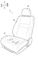
図1に示すように、本実施形態に係るシートは、自動車の運転席や助手席などに使用される車両用シートSとして構成され、乗員が着座するシートクッションS1と、乗員の上体を支持するシートバックS2と、乗員の頭部を支持可能なヘッドレストS3とを主に備えている。Hereinafter, an embodiment of the present invention will be described in detail with reference to the drawings as appropriate.
As shown in FIG. 1, the seat according to the present embodiment is configured as a vehicle seat S used for a driver's seat or a passenger seat of an automobile, and supports a seat cushion S1 on which an occupant is seated and an occupant's upper body. The seat back S2 to be used and the headrest S3 capable of supporting the head of the occupant are mainly provided.
シートクッションS1は、図示しない金属製のフレームと、ウレタンフォームなどのクッション材からなるシートクッションパッド1と、合成皮革や布地などからなる表皮材2とを主に備え、フレームにシートクッションパッド1を被せ、さらにシートクッションパッド1に表皮材2を被せることで構成されている。
The seat cushion S1 mainly includes a metal frame (not shown), a
詳細な構成については後述するが、シートクッションパッド1は、内部に形成された通気路1A(図5参照)と上面に形成された複数の送風口1Bを有し、図示しないブロワなどから通気路1A内に送り込まれた空気を図1に矢印で示すように送風口1Bから乗員に向けて送風可能に構成されている。なお、図示は省略するが、表皮材2が通気性の低い材料から形成されている場合には、表皮材2の送風口1Bと対応する位置には空気を通すための穴が形成される。
Although the detailed configuration will be described later, the
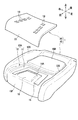
図2に示すように、シートクッションパッド1は、シートクッションS1のフレームに被せられるパッド本体10と、上面に複数の送風口1Bが形成されたカバー部材20とを主に有している。なお、パッド本体10とカバー部材20は、材質が同じであってもよいし、異なっていてもよい。
As shown in FIG. 2, the
パッド本体10の上面のうち、左右方向中央部の前側部分には、後側部分である中央後部10Bよりも凹んだ形状をなしてカバー部材20が係合可能な係合凹部10Aが形成されている。図3に示すように、係合凹部10Aは、第1凹部11と、第1凹部11の周囲で第1凹部11の底部11Aよりも1段高く形成された第2凹部12とから構成されている。第1凹部11内には、底部11Aよりも凹んだ形状の本体側通気凹部15と、底部11Aから上方に突出する本発明における凸部としての位置決め凸部16が主に形成されている。
Of the upper surface of the pad
本体側通気凹部15は、後述するカバー部材20のカバー側通気凹部25(図5参照)と対向して通気路1Aを形成する溝であり、平面視略U字形状に形成されている。この本体側通気凹部15の左右方向中央付近には、パッド本体10を上下に貫通する貫通穴15Aが形成されている。貫通穴15Aは、通気路1A内に空気を送り込むための穴である。
The main body
位置決め凸部16は、底部11Aの前側部分の左右方向中央部付近に配置されている。この位置決め凸部16は、左右方向の幅が後側よりも前側の方が大きくなるようなテーパ面を側面として有する平面視略台形状に形成されている。
The positioning
図3および図5に示すように、パッド本体10は、係合凹部10A(カバー部材20)や中央後部10Bの左右両側に、カバー部材20や中央後部10Bの上面よりも上に張り出した張出部10Sを有している。また、パッド本体10の左右両端部には、表皮材2に設けられるフック状の係合部2Hが係合可能な表皮取付部材の一例としての表皮取付ワイヤ50がそれぞれ設けられている。より詳細に説明すると、表皮取付ワイヤ50は、前後方向に沿って延び、第1凹部11よりも水平方向(左右方向)外側であって、張出部10Sと係合凹部10Aとの境界付近のパッド本体10内に埋設された状態で配置されている。この表皮取付ワイヤ50は、その一部がパッド本体10に形成された穴10Cから露出しており、この露出した部分に表皮材2の係合部2Hを係合させることで、表皮材2がパッド本体10(シートクッションパッド1)に固定される。
As shown in FIGS. 3 and 5, the pad
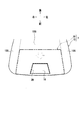
図4および図5に示すように、カバー部材20は、パッド本体10の係合凹部10Aに接着されることなく係合することでパッド本体10の上に配置されてパッド本体10との間に通気路1Aを形成する部材であり、カバー本体21と、延出縁部22と、前端部23(図6参照)とを主に有している。図6に示すように、係合凹部10Aに係合したカバー部材20の上面は、パッド本体10の中央後部10Bの上面と略面一となる。なお、図4は、下面側から見たカバー部材20の斜視図であるが、後述するカバー側通気凹部25や位置決め凹部26を分かりやすく示すため、前端部23を破断した状態で示している。
As shown in FIGS. 4 and 5, the
図4および図5に示すように、カバー本体21は、主にその下部がパッド本体10の第1凹部11に係合してパッド本体10との間に通気路1Aを形成する部分である。このカバー本体21の下面には、カバー側通気凹部25と、位置決め凹部26が形成されている。
As shown in FIGS. 4 and 5, the cover
カバー側通気凹部25は、カバー部材20がパッド本体10の係合凹部10Aに係合したときに本体側通気凹部15と互いに対向してパッド本体10との間に通気路1Aを形成する溝であり、本体側通気凹部15と同様に平面視略U字形状に形成されている。このカバー側通気凹部25の底面には、送風口1Bと連通する複数の連通穴25Aが形成されている。通気路1A内に送り込まれた空気は、この連通穴25Aを通って送風口1Bから送風される。
The cover-
位置決め凹部26は、パッド本体10の位置決め凸部16と嵌合する凹部であり、カバー本体21の下面の前側部分の左右方向中央部付近に配置されている。この位置決め凹部26は、位置決め凸部16と同様に、左右方向の幅が後側よりも前側の方が大きくなるような平面視略台形状に形成されている。
The positioning
図4に示すように、延出縁部22は、カバー本体21の周縁部の各辺の上部から第1凹部11の縁よりも水平方向外側(前後方向外側や左右方向外側)に突出するように延びる部分である。この延出縁部22は、カバー本体21の周縁部のうちの左右の辺から延びている左側縁部22Lおよび右側縁部22Rと、カバー本体21の周縁部のうちの前側の辺から延びている前側縁部22Fと、カバー本体21の周縁部のうちの後側の辺から延びている後側縁部22Bとから構成され、前側縁部22F、左側縁部22L、後側縁部22Bおよび右側縁部22Rが、カバー本体21を取り囲むように連続して略フランジ状に形成されている。カバー部材20が、パッド本体10の係合凹部10Aに係合したとき、延出縁部22は、パッド本体10の第2凹部12に入り込む。
As shown in FIG. 4, the extending
図5に示すように、左側縁部22Lおよび右側縁部22Rは、それぞれ、パッド本体10の張出部10Sに対面する位置まで延びている。より詳細に、左側縁部22Lおよび右側縁部22Rは、それぞれ、表皮取付ワイヤ50の近傍まで延びて、その端面が、パッド本体10との間で、表皮材2を吊り込んだり、表皮材2の係合部2Hを表皮取付ワイヤ50に係合させたりするための開口の一例としての吊り込み溝1Cの壁の一部を形成している。また、図6に示すように、前側縁部22Fは、パッド本体10の前端部10Fよりも前側まで延びている。
As shown in FIG. 5, the
前端部23は、前側縁部22Fから連続してパッド本体10の前端部10Fに沿うように下方に延びる部分である。言い換えると、前端部23は、パッド本体10の前端部10Fを前側から覆うように下方に延びている。
The
次に、以上のように構成された車両用シートSの作用効果について説明する。
なお、参考として示す図7(b)の比較例は、シートクッションパッド101に表皮材102を被せることで構成されたシートクッションS101である。シートクッションS101のシートクッションパッド101は、パッド本体110と、パッド本体110の上面に形成された凹部110Aに嵌め込まれた平板状のカバー部材120とを有し、パッド本体110とカバー部材120との間に通気路101Aが形成されている。Next, the effect of the vehicle seat S configured as described above will be described.
Note that the comparative example of FIG. 7B shown as a reference is a seat cushion S101 configured by covering the
図7(b)に示す比較例では、シートクッションS101に乗員が着座したとき、前から見て、カバー部材120の左右方向中央が沈み込んで弓なりに変形することで、その周縁部分がパッド本体110から浮き上がろうとする。これにより、カバー部材120の端部とパッド本体110との間に段差ができ、この段差が表皮材102を介して乗員に当たることで着座フィーリングが低下する。また、カバー部材120の端部とパッド本体110との間に隙間ができ、この隙間から通気路101A内の空気が漏れる可能性がある。
In the comparative example shown in FIG. 7B, when the occupant sits on the seat cushion S101, the center of the
一方、図6や図7(a)に示す本実施形態では、カバー部材20がカバー本体21の周縁部から延びる延出縁部22を有することで、仮にカバー本体21の端部とパッド本体10との間に隙間ができたとしても、延出縁部22とパッド本体10が接触することで隙間をシールできるため、通気路1Aからの空気漏れを抑制することができる。また、カバー本体21の周縁部から延びる延出縁部22を有することで、パッド本体10とカバー部材20との接触面積を大きくできるので、パッド本体10とカバー部材20との間に隙間自体ができにくく、これによっても通気路1Aからの空気漏れを抑制することができる。
On the other hand, in the present embodiment shown in FIG. 6 and FIG. 7A, the
また、延出縁部22のうち左側縁部22Lおよび右側縁部22Rは、表皮取付ワイヤ50の近傍まで延びて表皮材2を係合させるための吊り込み溝1Cの一部を形成しているため、表皮取付ワイヤ50に取り付けられた表皮材2によって比較的強固に押さえられることとなる。これにより、パッド本体10とカバー部材20との間に隙間がよりできにくくなるため、通気路1Aからの空気漏れをより抑制することができる。
Further, the
また、着座フィーリングの観点から言えば、図6に示すように、延出縁部22のうち前側縁部22Fは、パッド本体10の前端部10Fまで延びているので、シートクッションパッド1の上面に前側縁部22Fとパッド本体10との境目がない。これにより、着座時に仮に前側縁部22Fが浮き上がっても、シートクッションパッド1の上面前部に段差はできないため、着座フィーリングの低下を抑制することができる。
Further, from the viewpoint of the seating feeling, as shown in FIG. 6, the front
また、本実施形態では、カバー部材20の前端部23がパッド本体10の前端部10Fを覆うように下方にまで延びているので、着座時に前端部23が浮き上がったとしても、シートクッションパッド1の前端部にも段差はできない。これにより、着座フィーリングを向上させることができる。
In the present embodiment, since the
また、図7(a)に示すように、延出縁部22のうち左側縁部22Lおよび右側縁部22Rは、カバー本体21の周縁部のうちの左右の辺から延びて乗員から遠ざかっているので、着座時に仮に左側縁部22Lおよび右側縁部22Rが浮き上がっても、それは乗員から遠い位置で起こることになるため、着座フィーリングの低下を抑制することができる。
Further, as shown in FIG. 7A, the
さらに言えば、左側縁部22Lおよび右側縁部22Rは、パッド本体10の張出部10Sに対面する位置まで延びているため、着座時に左側縁部22Lおよび右側縁部22Rが浮き上がったとしても、乗員に違和感を与えることはない。これにより、着座フィーリングを向上させることができる。また、上記したとおり、左側縁部22Lおよび右側縁部22Rは、表皮材2によって比較的強固に押さえられるため、そもそも浮き上がりにくくなっており、着座フィーリングをより向上させることができる。
Furthermore, since the
なお、図7(b)に示す比較例では、着座時にカバー部材120の左右方向中央が沈み込むことで、その周縁部分が中央に向けて引っ張られ、カバー部材120の端面とパッド本体110との間に隙間ができやすくなっている。これにより、カバー部材120の端部が浮き上がりやすくなって、段差ができたり、隙間ができたりすることとなる。一方、図7(a)に示す本実施形態では、位置決め凸部16と位置決め凹部26の形成部分の特に左右両側において、カバー本体21の端面とパッド本体10との間に隙間ができにくくなっている。これは、カバー部材20の左右方向中央が沈み込んでその周縁部分が中央に向けて引っ張られても、位置決め凹部26の側面が位置決め凸部16の側面に当たることで、カバー部材20の周縁部分のうち位置決め凹部26よりも外側の部分が中央に向けて引っ張られにくくなっているためである。これにより、カバー部材20の端部の浮き上がりが抑制されるため、着座フィーリングをより向上させることができるとともに、カバー部材20の端部とパッド本体10との間に隙間ができにくいので通気路1Aからの空気漏れを一層抑制することができる。
In the comparative example shown in FIG. 7B, when the
また、本実施形態では、パッド本体10の上面に形成された位置決め凸部16と、カバー部材20の下面に形成された位置決め凹部26とが嵌合することで、パッド本体10とカバー部材20を接着剤などで接着しない構成においても、パッド本体10に対するカバー部材20のずれを抑制することができる。
Moreover, in this embodiment, the positioning
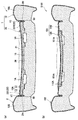
特に本実施形態では、図8に示すように、位置決め凸部16と位置決め凹部26は、左右方向の幅が後側よりも前側の方が大きくなるような平面視略台形状に形成されているため、互いに嵌合したときに左右の面がいわば噛み合うことで、特にパッド本体10に対するカバー部材20の前方へのずれを効果的に抑制することができる。
In particular, in the present embodiment, as shown in FIG. 8, the positioning
また、本実施形態では、位置決め凸部16と位置決め凹部26がシートクッションパッド1の前側部分の左右方向中央部、言い換えれば、乗員の左右の大腿部の間に対応する位置付近に形成されているので、位置決め凸部16と位置決め凹部26の形成部分に真上から荷重がかかりにくくなっている。そのため、位置決め凸部16や位置決め凹部26の大きな変形を抑制できるので、位置決め凸部16と位置決め凹部26との係合状態を良好に保つことができ、パッド本体10に対するカバー部材20のずれをより抑制することができる。
Further, in the present embodiment, the positioning
また、図5に示すように、本実施形態では、パッド本体10とカバー部材20の両方が通気路1Aを形成するための通気凹部15,25を有するので、どちらか一方だけが通気凹部を有する構成と比較して、通気路1Aの断面積を確保することができる。これにより、乗員の着座によって変形するシートクッションパッド1内において、空気を通すためのスペースを確保することができる。
Further, as shown in FIG. 5, in this embodiment, since both the
以上、本発明の実施形態について説明したが、本発明は前記実施形態に限定されるものではない。具体的な構成については、下記のように本発明の趣旨を逸脱しない範囲で適宜変更が可能である。 As mentioned above, although embodiment of this invention was described, this invention is not limited to the said embodiment. About a concrete structure, it can change suitably in the range which does not deviate from the meaning of this invention as follows.
前記実施形態では、パッド本体10の上面に位置決め凸部16が形成され、カバー部材20の下面に位置決め凹部26が形成されていたが、これに限定されるものではない。例えば、図9に示すように、パッド本体10の上面に位置決め凹部17が形成され、カバー部材20の下面に位置決め凸部27が形成されていてもよい。この場合、位置決め凹部17および位置決め凸部27の左右方向の幅は、前記実施形態とは逆に、前側よりも後側の方が大きくなるように形成されていることが望ましい。これによれば、図10に示すように、互いに嵌合したときに左右の面が噛み合うことで、パッド本体10に対するカバー部材20の前方へのずれを効果的に抑制することができる。
In the above-described embodiment, the positioning
なお、前記実施形態や図9に示した形態では、位置決め凸部16,27や位置決め凹部26,17は、その左右の面が略平面状の傾斜面として形成されていたが、これに限定されず、例えば、1段以上の段差を有する階段状の面として形成されていてもよい。また、前記実施形態や図9に示した形態では、位置決め凸部16,27と位置決め凹部26,17がシートクッションパッド1の前側部分の左右方向中央部に1組形成されていたが、これに限定されるものではない。例えば、位置決め凸部と位置決め凹部は、シートクッションパッドの前側部分の左右方向中央部以外に形成されていてもよいし、2組以上形成されていてもよい。
In the embodiment and the embodiment shown in FIG. 9, the positioning
前記実施形態では、延出縁部22が、カバー本体21を取り囲むように、カバー本体21の周縁部の各辺から延びるように形成されていたが、これに限定されるものではない。例えば、延出縁部は、カバー本体の周縁部のうち左右の辺だけから延びるように形成されていてもよいし、カバー本体の周縁部のうち前側の辺だけから延びるように形成されていてもよい。
In the said embodiment, although the
前記実施形態では、パッド本体10とカバー部材20の両方に通気路1Aを形成する通気凹部15,25が形成されていたが、これに限定されるものではない。例えば、通気凹部は、パッド本体だけに形成されていてもよいし、カバー部材だけに形成されていてもよい。
In the embodiment described above, the ventilation recesses 15 and 25 that form the
前記実施形態では、パッド本体10が一つの部品で構成されていたが、パッド本体の構成はこれに限定されるものではない。例えば、図11に示すように、パッド本体200は、第1本体部210と、第1本体部210とカバー部材20の間に配置される第2本体部220との二つの部品で構成されていてもよい。
In the embodiment, the pad
具体的に、第1本体部210は、前記実施形態におけるパッド本体10と同様に、第1凹部11を有する係合凹部10A、中央後部10Bおよび張出部10Sを有している。第1本体部210は、第1凹部11の後部に、上下に貫通した貫通穴211が形成されている。そして、第1凹部11の底面212は、貫通穴211以外に凹凸が設けられておらず、略平面状に形成されている。
Specifically, the first
また、第1本体部210は、前端部に前側が低くなった段差の一例としての前側段差213が設けられている。具体的に、第1本体部210は、前端部の下部に、前側に突出する突出部230が設けられている。突出部230は、第1本体部210の左端から右端にわたって設けられている。この突出部230は、第1凹部11の底面212よりも低い位置に設けられた上を向く当接面231を有している。そして、第1本体部210の第1凹部11の底面212と当接面231との間の部分が、前側段差213となっている。
Further, the first
第2本体部220は、第1本体部210の上面、詳しくは、第1凹部11の底面212と重なる矩形状の通気路形成部220Aと、通気路形成部220Aから前側下方へ向けて延びる前端部220Bとを有している。この第2本体部220は、第1本体部210またはカバー部材20と材質が同じであってもよいし、異なっていてもよい。
The second
通気路形成部220Aは、上下に貫通した通気溝221が形成されている。この通気路形成部220Aは、第1凹部11上に配置されることで、図12に示すように、通気溝221と第1凹部11の底面212で本体側通気凹部15を形成している。
The ventilation
図11に戻り、通気溝221は、平面視略U字形状に形成された第1通気溝221Aと、第2本体部220の貫通穴211に重なる位置から延びて第1通気溝221Aに繋がる第2通気溝221Bとを有している。
Returning to FIG. 11, the
そして、図13に示すように、第2本体部220の前端部220Bは、第1本体部210の前側段差213の一部を覆うように設けられ、下端が、突出部230の当接面231に接触している。また、第2本体部220の後端部(通気路形成部220Aの後端部222)は、第1本体部210の第1凹部11と中央後部10Bの間の段差である後側段差214に接触している。
As shown in FIG. 13, the
図12に示すように、カバー部材20は、前記実施形態と異なり、下面にカバー側通気凹部を有しておらず、略平板状に形成されている。このカバー部材20は、その下面が、本体側通気凹部15とともに通気路1Aを形成している。そして、カバー部材20は、本体側通気凹部15と重なる位置に、複数の送風口1Bが形成されている。なお、カバー部材20は、前記実施形態と同様に、下面にカバー側通気凹部を有していてもよい。
As shown in FIG. 12, the
そして、図13に示すように、カバー部材20の前端部23は、第2本体部220の前端部220Bに重なり、下端が第1本体部210の当接面231に接触している。
As shown in FIG. 13, the
以上のように、第1本体部210とカバー部材20の間に、通気路1Aを形成する第2本体部220を設けたことにより、前記実施形態のようにパッド本体10の本体側通気凹部15とカバー部材20のカバー側通気凹部25によって通気路1Aを形成する場合よりも、車両用シートSに乗員が着座したときの通気路1Aの変形を抑えることができる。
As described above, by providing the second
また、第2本体部220の前端部220Bが下方に向けて延びているので、着座時に第2本体部220の前端部220Bが浮き上がったとしても、パッド本体10の上面前部には段差ができないので、着座フィーリングの低下を抑制することができる。
In addition, since the
そして、第2本体部220の前端部220Bは、突出部230の当接面231に接触しているので、第2本体部220の下方へのずれを抑えることができる。また、第2本体部220の前端部220Bが、前側段差213に接触し、第2本体部220の後端部(通気路形成部220Aの後端部222)が、後側段差214に接触しているので、第2本体部220の後方へのずれを抑えることができる。
And since the front-
また、本変形例においては、カバー部材20の前端部23が、突出部230の当接面231に接触しているので、カバー部材20の下方へのずれを抑えることができる。
Further, in the present modification, the
なお、本変形例では、第2本体部220の前端部220Bとカバー部材20の前端部23の両方が突出部230の当接面231に接触していたが、第2本体部220の前端部220Bとカバー部材20の前端部23の一方のみを突出部230の当接面231に当接させる構成であってもよい。
In this modification, both the
前記実施形態では、本発明を自動車で使用されるシート(車両用シートS)に適用した例を示したが、これに限定されず、その他の乗物、例えば、鉄道車両や船舶、航空機などで使用されるシートに適用することもできる。また、本発明は、乗物用シートに限定されず、例えば、映画館などの公共施設や家庭などで使用されるシートに適用することもできる。 In the above-described embodiment, an example in which the present invention is applied to a seat (vehicle seat S) used in an automobile has been described. However, the present invention is not limited thereto, and is used in other vehicles such as a railway vehicle, a ship, and an aircraft. It can also be applied to a sheet to be processed. Further, the present invention is not limited to a vehicle seat, and may be applied to a seat used in public facilities such as a movie theater or at home.
Claims (11)
前記シートクッションパッドは、パッド本体と、前記パッド本体の上に配置されて前記パッド本体との間に前記通気路を形成するとともに前記送風口が形成されたカバー部材と、を有し、
前記パッド本体は、第1本体部と、前記第1本体部と前記カバー部材の間に配置され、前記第1本体部の上面と重なるとともに前端部が下方へ向けて延びる第2本体部とを有し、
前記カバー部材の前端部は、前記第2本体部の前端部を覆うように下方に延びていることを特徴とするシート。 A seat cushion pad having an air passage formed inside and a blower opening formed on the upper surface, and is configured to be able to blow air from the air vent through the air vent,
The seat cushion pad includes a pad main body, and a cover member that is disposed on the pad main body and forms the ventilation path between the pad main body and the air blowing port.
The pad main body includes a first main body portion, and a second main body portion that is disposed between the first main body portion and the cover member, overlaps with an upper surface of the first main body portion, and a front end portion extends downward. Have
The front end portion of the cover member extends downward so as to cover the front end portion of the second main body portion .
前記第2本体部の前端部および前記カバー部材の前端部の少なくとも一方は、前記第1本体部の前記段差より前側に配置される上を向く面に接触することを特徴とする請求項1に記載のシート。 The first main body is provided with a step at the front end that is lowered on the front side,
Wherein at least one of the front end portion of the front end portion and the cover member of the second body portion to claim 1, characterized in that contact with the surface facing the upper disposed forward of the step of the first body portion The described sheet.
前記シートクッションパッドは、パッド本体と、前記パッド本体の上に配置されて前記パッド本体との間に前記通気路を形成するとともに前記送風口が形成されたカバー部材と、を有し、
前記カバー部材の前端部は、前記パッド本体の前端部を覆うように下方に延びており、
前記パッド本体の上面には、凸部が形成され、前記カバー部材の下面には、前記凸部と嵌合して左右の面が前記凸部の左右の面に接触する位置決め凹部が形成され、
前記凸部および前記位置決め凹部は、左右の面の左右方向の間隔が、後側よりも前側の方が大きいことを特徴とするシート。 A seat cushion pad having an air passage formed inside and a blower opening formed on the upper surface, and is configured to be able to blow air from the air vent through the air vent,
The seat cushion pad includes a pad main body, and a cover member that is disposed on the pad main body and forms the ventilation path between the pad main body and the air blowing port.
The front end of the cover member extends downward to cover the front end of the pad body ,
A convex portion is formed on the upper surface of the pad body, and a positioning concave portion is formed on the lower surface of the cover member so that the left and right surfaces are in contact with the left and right surfaces of the convex portion by fitting with the convex portion.
The sheet, wherein the convex portion and the positioning concave portion have a larger distance in the left-right direction between the left and right surfaces on the front side than on the rear side .
前記シートクッションパッドは、パッド本体と、前記パッド本体の上に配置されて前記パッド本体との間に前記通気路を形成するとともに前記送風口が形成されたカバー部材と、を有し、
前記カバー部材の前端部は、前記パッド本体の前端部を覆うように下方に延びており、
前記カバー部材の下面には、凸部が形成され、前記パッド本体の上面には、前記凸部と嵌合して左右の面が前記凸部の左右の面に接触する位置決め凹部が形成され、
前記凸部および前記位置決め凹部は、左右の面の左右方向の間隔が、前側よりも後側の方が大きいことを特徴とするシート。 A seat cushion pad having an air passage formed inside and a blower opening formed on the upper surface, and is configured to be able to blow air from the air vent through the air vent,
The seat cushion pad includes a pad main body, and a cover member that is disposed on the pad main body and forms the ventilation path between the pad main body and the air blowing port.
The front end of the cover member extends downward to cover the front end of the pad body ,
A convex portion is formed on the lower surface of the cover member, and a positioning concave portion is formed on the upper surface of the pad body so that the left and right surfaces are brought into contact with the left and right surfaces of the convex portion by fitting with the convex portion.
The sheet, wherein the convex portion and the positioning concave portion have a lateral distance between left and right surfaces that is greater on the rear side than on the front side .
前記カバー部材は、前記第1凹部に係合して前記パッド本体との間に前記通気路を形成するカバー本体と、前記カバー本体の周縁部のうちの少なくとも1つの辺から前記第1凹部の縁よりも水平方向外側に延びる延出縁部と、を有することを特徴とする請求項3から請求項5のいずれか1項に記載のシート。 The pad body has a first recess formed on the upper surface,
The cover member engages with the first recess to form the air passage between the cover main body and at least one side of the peripheral edge of the cover body from the side of the first recess. The sheet according to any one of claims 3 to 5 , further comprising an extended edge portion extending outward in the horizontal direction from the edge.
前記パッド本体には、前記表皮材に設けられる係合部が係合可能な表皮取付部材が前記第1凹部よりも水平方向外側に設けられ、
前記延出縁部は、前記表皮取付部材の近傍まで延びて前記係合部を前記表皮取付部材に係合させるための開口の一部を形成していることを特徴とする請求項6に記載のシート。 A skin material that covers the seat cushion pad is provided,
The pad main body is provided with a skin attachment member engageable with an engagement portion provided on the skin material on the outer side in the horizontal direction than the first recess,
The extension chime is claimed in claim 6, characterized in that it forms part of the opening for engaging the engaging portion extends to the vicinity of the skin attachment member to the skin attachment member Sheet.
前記延出縁部は、前記張出部に対面する位置まで延びていることを特徴とする請求項8に記載のシート。 The pad body has a protruding portion that protrudes above the cover member on both the left and right sides of the cover member,
The sheet according to claim 8 , wherein the extending edge portion extends to a position facing the protruding portion.
Applications Claiming Priority (3)
| Application Number | Priority Date | Filing Date | Title |
|---|---|---|---|
| JP2013179238 | 2013-08-30 | ||
| JP2013179238 | 2013-08-30 | ||
| PCT/JP2014/072792 WO2015030195A1 (en) | 2013-08-30 | 2014-08-29 | Seat |
Related Child Applications (1)
| Application Number | Title | Priority Date | Filing Date |
|---|---|---|---|
| JP2018089008A Division JP6558467B2 (en) | 2013-08-30 | 2018-05-07 | Sheet |
Publications (2)
| Publication Number | Publication Date |
|---|---|
| JPWO2015030195A1 JPWO2015030195A1 (en) | 2017-03-02 |
| JP6336989B2 true JP6336989B2 (en) | 2018-06-06 |
Family
ID=52586741
Family Applications (5)
| Application Number | Title | Priority Date | Filing Date |
|---|---|---|---|
| JP2015534342A Active JP6336989B2 (en) | 2013-08-30 | 2014-08-29 | Sheet |
| JP2018089008A Active JP6558467B2 (en) | 2013-08-30 | 2018-05-07 | Sheet |
| JP2019128582A Active JP6908862B2 (en) | 2013-08-30 | 2019-07-10 | Seat |
| JP2021108296A Active JP7277808B2 (en) | 2013-08-30 | 2021-06-30 | sheet |
| JP2023074479A Pending JP2023086966A (en) | 2013-08-30 | 2023-04-28 | seat |
Family Applications After (4)
| Application Number | Title | Priority Date | Filing Date |
|---|---|---|---|
| JP2018089008A Active JP6558467B2 (en) | 2013-08-30 | 2018-05-07 | Sheet |
| JP2019128582A Active JP6908862B2 (en) | 2013-08-30 | 2019-07-10 | Seat |
| JP2021108296A Active JP7277808B2 (en) | 2013-08-30 | 2021-06-30 | sheet |
| JP2023074479A Pending JP2023086966A (en) | 2013-08-30 | 2023-04-28 | seat |
Country Status (4)
| Country | Link |
|---|---|
| US (5) | US9707875B2 (en) |
| JP (5) | JP6336989B2 (en) |
| CN (2) | CN105491915B (en) |
| WO (1) | WO2015030195A1 (en) |
Families Citing this family (18)
| Publication number | Priority date | Publication date | Assignee | Title |
|---|---|---|---|---|
| JP6336989B2 (en) | 2013-08-30 | 2018-06-06 | テイ・エス テック株式会社 | Sheet |
| JP6015717B2 (en) * | 2014-07-08 | 2016-10-26 | トヨタ自動車株式会社 | Vehicle seat |
| JP6480215B2 (en) * | 2015-03-06 | 2019-03-06 | 株式会社タチエス | Vehicle seat |
| CN205970959U (en) * | 2016-07-07 | 2017-02-22 | 陈广 | Children's seatpad that ventilates |
| CN116424181A (en) * | 2016-09-02 | 2023-07-14 | 捷温有限责任公司 | Heating type decorative mask, automobile seat provided with same and manufacturing method of automobile seat |
| JP6700556B2 (en) * | 2016-09-30 | 2020-05-27 | テイ・エス テック株式会社 | Sheet |
| US11135949B2 (en) | 2016-09-30 | 2021-10-05 | Ts Tech Co., Ltd. | Seat with blower |
| WO2018079041A1 (en) * | 2016-10-24 | 2018-05-03 | 株式会社デンソー | Air-permeable sheet and seat air-conditioning device |
| WO2018105264A1 (en) * | 2016-12-08 | 2018-06-14 | 株式会社デンソー | Seat air-conditioning device |
| JP6652713B2 (en) * | 2017-03-01 | 2020-02-26 | テイ・エス テック株式会社 | Vehicle seat |
| JP6643727B2 (en) * | 2017-03-01 | 2020-02-12 | テイ・エス テック株式会社 | Vehicle seat |
| JP6356882B1 (en) * | 2017-07-31 | 2018-07-11 | テイ・エス テック株式会社 | Sensor arrangement structure on the seat |
| JP7197760B2 (en) * | 2017-09-05 | 2022-12-28 | テイ・エス テック株式会社 | vehicle seat |
| GB2580026B (en) * | 2018-12-19 | 2023-02-22 | Safran Seats Gb Ltd | Aircraft seat |
| JP7017285B2 (en) * | 2020-03-06 | 2022-02-08 | テイ・エス テック株式会社 | Vehicle seat and its assembly method |
| JP7029089B2 (en) * | 2020-04-23 | 2022-03-03 | テイ・エス テック株式会社 | Seat |
| JP7409238B2 (en) * | 2020-06-30 | 2024-01-09 | 株式会社デンソー | Seat air conditioner |
| JPWO2023013432A1 (en) * | 2021-08-02 | 2023-02-09 |
Family Cites Families (36)
| Publication number | Priority date | Publication date | Assignee | Title |
|---|---|---|---|---|
| US3550523A (en) * | 1969-05-12 | 1970-12-29 | Irving Segal | Seat construction for automotive air conditioning |
| US5597200A (en) * | 1993-11-22 | 1997-01-28 | Amerigon, Inc. | Variable temperature seat |
| JPH11137371A (en) * | 1997-11-10 | 1999-05-25 | Aisin Seiki Co Ltd | Air permeable seat device |
| US6179706B1 (en) * | 1998-06-19 | 2001-01-30 | Denso Corporation | Seat air conditioner for vehicle |
| EP1086852B1 (en) * | 1999-09-21 | 2004-01-28 | Johnson Controls GmbH | Seat cushion for vehicle seats |
| DE10024880C1 (en) | 2000-05-19 | 2001-09-06 | Daimler Chrysler Ag | Actively-ventilated seat module for automobile passenger seat has ventilated cushion zone with mesh layer between 2 rubber fibre layers |
| DE10037065B4 (en) * | 2000-07-29 | 2010-12-23 | Daimler Ag | Cushion for an actively ventilated vehicle seat |
| US7040710B2 (en) * | 2001-01-05 | 2006-05-09 | Johnson Controls Technology Company | Ventilated seat |
| JP4179497B2 (en) | 2002-11-18 | 2008-11-12 | 関東自動車工業株式会社 | seat |
| JP4013765B2 (en) | 2003-01-14 | 2007-11-28 | 株式会社デンソー | Vehicle seat air conditioner |
| DE20308535U1 (en) | 2003-05-30 | 2003-08-14 | Faurecia Autositze Gmbh & Co | Ventilated seat for motor vehicle incorporates air passage within support for padded cushion and on end pointing towards cushion cover opens out into air channels extending approximately parallel to cushion cover |
| JP4347646B2 (en) * | 2003-09-24 | 2009-10-21 | 東洋ゴム工業株式会社 | Cushion pad |
| US20050200166A1 (en) * | 2004-03-09 | 2005-09-15 | Ki-Yeong Noh | Vehicle seat with cooling/heating device |
| JP2005287532A (en) | 2004-03-31 | 2005-10-20 | T S Tec Kk | Car seat |
| US7828050B2 (en) * | 2004-09-02 | 2010-11-09 | Honda Motor Co., Ltd. | Vehicle seat air-conditioner and vehicle temperature controller |
| JP2006102329A (en) * | 2004-10-07 | 2006-04-20 | T S Tec Kk | Seat for vehicle |
| FR2882308B1 (en) * | 2005-02-22 | 2007-05-25 | Cera | METHOD FOR PRODUCING A VENTILATED GARMENT COMPONENT |
| US7862113B2 (en) * | 2006-01-30 | 2011-01-04 | Igb Automotive Ltd. | Modular comfort assembly diffuser bag having integral air mover support |
| DE102006047370A1 (en) * | 2006-10-06 | 2008-04-10 | Bayerische Motoren Werke Ag | Active ventilated vehicle seat |
| JP2008125829A (en) * | 2006-11-21 | 2008-06-05 | Bridgestone Corp | Vehicle seat pad |
| US20090033130A1 (en) * | 2007-07-02 | 2009-02-05 | David Marquette | Fluid delivery systems for climate controlled seats |
| JP5103114B2 (en) * | 2007-09-25 | 2012-12-19 | トヨタ紡織株式会社 | Air conditioning sheet |
| JP2009090016A (en) * | 2007-10-11 | 2009-04-30 | T S Tec Kk | Seat, seat cushion and backrest thereof |
| US20090152909A1 (en) * | 2007-12-12 | 2009-06-18 | Lear Corporation | Attachment assembly for securing trim material to the padding of a ventilated seat |
| FR2925415A1 (en) * | 2007-12-20 | 2009-06-26 | Sarl Lecorney Sarl | HEADQUARTERS IN PARTICULAR VEHICLES |
| DE102008038380B4 (en) * | 2008-08-19 | 2010-11-11 | Lear Corp., Southfield | Alignment system for a spacer layer in a ventilated seat |
| US20110059667A1 (en) * | 2009-09-09 | 2011-03-10 | Johnson Controls Technology Company | Cover with a spray on fabric |
| JP2012218655A (en) * | 2011-04-13 | 2012-11-12 | Nissan Motor Co Ltd | Vehicle seat |
| JP5765039B2 (en) | 2011-04-20 | 2015-08-19 | トヨタ紡織株式会社 | Vehicle seat |
| JP6149866B2 (en) * | 2012-12-05 | 2017-06-21 | パナソニックIpマネジメント株式会社 | Vehicle heating system and vehicle seat with heating |
| EP2933135B1 (en) * | 2012-12-14 | 2020-04-15 | Panasonic Intellectual Property Management Co., Ltd. | Vehicle-mounted heater device |
| US9676309B2 (en) * | 2013-06-03 | 2017-06-13 | Panasonic Intellectual Property Management Co., Ltd. | Vehicle heating apparatus and heater-equipped vehicle seat |
| JP6336989B2 (en) * | 2013-08-30 | 2018-06-06 | テイ・エス テック株式会社 | Sheet |
| JP6337735B2 (en) * | 2014-10-16 | 2018-06-06 | トヨタ紡織株式会社 | Vehicle seat |
| US20160157617A1 (en) * | 2014-12-04 | 2016-06-09 | Lear Corporation | Thoracic region comfort seating system |
| US10179526B2 (en) * | 2015-05-12 | 2019-01-15 | Gentherm Inc. | Enhanced climate seat with asymmetric thermal management system and method |
-
2014
- 2014-08-29 JP JP2015534342A patent/JP6336989B2/en active Active
- 2014-08-29 WO PCT/JP2014/072792 patent/WO2015030195A1/en active Application Filing
- 2014-08-29 CN CN201480047696.1A patent/CN105491915B/en active Active
- 2014-08-29 CN CN201910678574.7A patent/CN110435509A/en active Pending
- 2014-08-29 US US14/914,546 patent/US9707875B2/en active Active
-
2017
- 2017-06-09 US US15/618,942 patent/US10124705B2/en active Active
-
2018
- 2018-05-07 JP JP2018089008A patent/JP6558467B2/en active Active
- 2018-10-03 US US16/150,627 patent/US10752140B2/en active Active
-
2019
- 2019-07-10 JP JP2019128582A patent/JP6908862B2/en active Active
-
2020
- 2020-08-21 US US16/999,751 patent/US11458870B2/en active Active
-
2021
- 2021-06-30 JP JP2021108296A patent/JP7277808B2/en active Active
-
2022
- 2022-08-05 US US17/882,183 patent/US11787317B2/en active Active
-
2023
- 2023-04-28 JP JP2023074479A patent/JP2023086966A/en active Pending
Also Published As
| Publication number | Publication date |
|---|---|
| JP2018140211A (en) | 2018-09-13 |
| US20160207431A1 (en) | 2016-07-21 |
| JP7277808B2 (en) | 2023-05-19 |
| US10752140B2 (en) | 2020-08-25 |
| US20190031059A1 (en) | 2019-01-31 |
| JP2021164675A (en) | 2021-10-14 |
| US20220371489A1 (en) | 2022-11-24 |
| CN105491915A (en) | 2016-04-13 |
| CN110435509A (en) | 2019-11-12 |
| JPWO2015030195A1 (en) | 2017-03-02 |
| JP2019181245A (en) | 2019-10-24 |
| US11787317B2 (en) | 2023-10-17 |
| US9707875B2 (en) | 2017-07-18 |
| JP2023086966A (en) | 2023-06-22 |
| JP6908862B2 (en) | 2021-07-28 |
| US20170274804A1 (en) | 2017-09-28 |
| CN105491915B (en) | 2019-08-30 |
| US11458870B2 (en) | 2022-10-04 |
| WO2015030195A1 (en) | 2015-03-05 |
| US20200376991A1 (en) | 2020-12-03 |
| US10124705B2 (en) | 2018-11-13 |
| JP6558467B2 (en) | 2019-08-14 |
Similar Documents
| Publication | Publication Date | Title |
|---|---|---|
| JP6558467B2 (en) | Sheet | |
| JP6202949B2 (en) | Sheet | |
| JP6276042B2 (en) | Vehicle seat | |
| US9211825B2 (en) | Conveyance seat | |
| JP6098616B2 (en) | Vehicle seat | |
| JP2015137021A (en) | vehicle seat | |
| JP6144169B2 (en) | Vehicle seat | |
| JP6131862B2 (en) | Vehicle seat | |
| JP5994674B2 (en) | Vehicle seat | |
| JP6838429B2 (en) | Air conditioning sheet | |
| JP5569172B2 (en) | Sheet with air blowing function | |
| JP5653689B2 (en) | Seat pad and manufacturing method thereof | |
| JP5891951B2 (en) | Vehicle seat | |
| JP5818228B2 (en) | Vehicle interior structure | |
| JP2023132991A (en) | Seat pad and vehicle seat | |
| JP2019034642A (en) | Vehicular seat | |
| KR20130039166A (en) | Crashpad for an automobile | |
| JP2014218178A (en) | Vehicular seat |
Legal Events
| Date | Code | Title | Description |
|---|---|---|---|
| A621 | Written request for application examination |
Free format text: JAPANESE INTERMEDIATE CODE: A621 Effective date: 20170328 |
|
| A131 | Notification of reasons for refusal |
Free format text: JAPANESE INTERMEDIATE CODE: A131 Effective date: 20171205 |
|
| A521 | Request for written amendment filed |
Free format text: JAPANESE INTERMEDIATE CODE: A523 Effective date: 20180115 |
|
| TRDD | Decision of grant or rejection written | ||
| A01 | Written decision to grant a patent or to grant a registration (utility model) |
Free format text: JAPANESE INTERMEDIATE CODE: A01 Effective date: 20180403 |
|
| A61 | First payment of annual fees (during grant procedure) |
Free format text: JAPANESE INTERMEDIATE CODE: A61 Effective date: 20180507 |
|
| R150 | Certificate of patent or registration of utility model |
Ref document number: 6336989 Country of ref document: JP Free format text: JAPANESE INTERMEDIATE CODE: R150 |
|
| R250 | Receipt of annual fees |
Free format text: JAPANESE INTERMEDIATE CODE: R250 |
|
| R250 | Receipt of annual fees |
Free format text: JAPANESE INTERMEDIATE CODE: R250 |
|
| R250 | Receipt of annual fees |
Free format text: JAPANESE INTERMEDIATE CODE: R250 |