EP3662975A2 - Flexible trockensprinkler - Google Patents
Flexible trockensprinkler Download PDFInfo
- Publication number
- EP3662975A2 EP3662975A2 EP19207309.6A EP19207309A EP3662975A2 EP 3662975 A2 EP3662975 A2 EP 3662975A2 EP 19207309 A EP19207309 A EP 19207309A EP 3662975 A2 EP3662975 A2 EP 3662975A2
- Authority
- EP
- European Patent Office
- Prior art keywords
- inlet
- outlet
- flexible
- dry sprinkler
- linkage
- Prior art date
- Legal status (The legal status is an assumption and is not a legal conclusion. Google has not performed a legal analysis and makes no representation as to the accuracy of the status listed.)
- Pending
Links
Images


Classifications
-
- A—HUMAN NECESSITIES
- A62—LIFE-SAVING; FIRE-FIGHTING
- A62C—FIRE-FIGHTING
- A62C35/00—Permanently-installed equipment
- A62C35/58—Pipe-line systems
- A62C35/62—Pipe-line systems dry, i.e. empty of extinguishing material when not in use
-
- A—HUMAN NECESSITIES
- A62—LIFE-SAVING; FIRE-FIGHTING
- A62C—FIRE-FIGHTING
- A62C31/00—Delivery of fire-extinguishing material
- A62C31/02—Nozzles specially adapted for fire-extinguishing
-
- A—HUMAN NECESSITIES
- A62—LIFE-SAVING; FIRE-FIGHTING
- A62C—FIRE-FIGHTING
- A62C31/00—Delivery of fire-extinguishing material
- A62C31/28—Accessories for delivery devices, e.g. supports
-
- A—HUMAN NECESSITIES
- A62—LIFE-SAVING; FIRE-FIGHTING
- A62C—FIRE-FIGHTING
- A62C33/00—Hose accessories
- A62C33/04—Supports or clamps for fire hoses
-
- A—HUMAN NECESSITIES
- A62—LIFE-SAVING; FIRE-FIGHTING
- A62C—FIRE-FIGHTING
- A62C35/00—Permanently-installed equipment
- A62C35/58—Pipe-line systems
-
- A—HUMAN NECESSITIES
- A62—LIFE-SAVING; FIRE-FIGHTING
- A62C—FIRE-FIGHTING
- A62C37/00—Control of fire-fighting equipment
- A62C37/08—Control of fire-fighting equipment comprising an outlet device containing a sensor, or itself being the sensor, i.e. self-contained sprinklers
- A62C37/10—Releasing means, e.g. electrically released
- A62C37/11—Releasing means, e.g. electrically released heat-sensitive
- A62C37/14—Releasing means, e.g. electrically released heat-sensitive with frangible vessels
-
- A—HUMAN NECESSITIES
- A62—LIFE-SAVING; FIRE-FIGHTING
- A62C—FIRE-FIGHTING
- A62C37/00—Control of fire-fighting equipment
- A62C37/36—Control of fire-fighting equipment an actuating signal being generated by a sensor separate from an outlet device
- A62C37/38—Control of fire-fighting equipment an actuating signal being generated by a sensor separate from an outlet device by both sensor and actuator, e.g. valve, being in the danger zone
- A62C37/42—Control of fire-fighting equipment an actuating signal being generated by a sensor separate from an outlet device by both sensor and actuator, e.g. valve, being in the danger zone with mechanical connection between sensor and actuator, e.g. rods, levers
Definitions
- Dry sprinklers are used in areas that are exposed to freezing conditions, such as in freezers or walkways that may experience freezing conditions.
- supply conduits run in a space where the fluid in the supply conduit is not subject to freezing.
- a dry sprinkler is attached to the supply conduit and extends into a space where the fluid would otherwise be subject to freezing.
- the typical construction of a dry sprinkler comprises a sprinkler head, a tube, a pipe connector at the inlet end of the tube (for connecting the inlet end to the pipe network of the fire suppression system), a plug seal at the inlet end to prevent water from entering the tube until it is necessary to actuate the sprinkler, and an actuating mechanism to maintain the plug seal at the inlet end until actuation.
- the sprinkler head is attached to the end of the tube opposite to the inlet end of the tube.
- the tube is conventionally vented to the atmosphere to allow drainage of any condensate that may form in the tube.
- the actuating mechanism can be a rod or other similar structure that extends through the tube between the sprinkler head and the inlet end to maintain the seal at the inlet end.
- the actuating mechanism includes a thermally responsive support element at the sprinkler head that supports the rod and therefore the seal at the inlet end.
- the tube is also sealed at the sprinkler head end of the tube and the actuating mechanism is supported at the sprinkler head end by a seal cap supported by the thermally responsive support element.
- the space in the tube between the two seal caps can be pressurized with a gas, such as dry air or nitrogen or with a liquid such as an antifreeze solution.
- a gas such as dry air or nitrogen
- a liquid such as an antifreeze solution.
- Conventional dry sprinklers are fabricated using a rigid tube having a seal at the inlet that is separated from the sprinkler's temperature sensor, which is intended to be positioned in an area exposed to freezing conditions, such as an area that is not heated.
- the rigid tube extends into the unheated area from a wet pipe system (located in a heated area) and must be precisely aligned and installed while avoiding various architectural, structural and mechanical obstructions typically found in commercial or industrial buildings.
- a dry sprinkler which has a flexible tube.
- the dry sprinkler includes an inlet having an inlet orifice sealed by an inlet seal assembly and having a release mechanism for selectively releasing the inlet seal assembly.
- the dry sprinkler also includes a flexible tube attached to the inlet at a first end of the flexible tube.
- the dry sprinkler includes a flexible linkage extending longitudinally within the flexible tube between the inlet and outlet, the flexible linkage constructed to operatively release the release mechanism in response to axial translation of the flexible linkage.
- the dry sprinkler also includes an outlet attached to the flexible tube, the outlet including a fire sprinkler portion having a thermally responsive element constructed to support an outlet seal assembly in an unresponsive state. In a case where the thermally responsive element is in a responsive state, the outlet seal assembly is released and the flexible linkage translates in an outlet direction at least an inlet stroke distance to activate the release mechanism to release the inlet seal assembly.
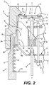
- the sprinkler 100 includes an inlet 1, a flexible tube 3, and an outlet 2.
- the flexible tube 3 extends between the inlet 1 and outlet 2 and is in mechanical and fluid communication therewith.
- the flexible tube 3 also has an inlet end 6 connected to an inlet biasing portion 4 of the inlet 1 by a threaded connection and also has an outlet end 7 connected to an outlet biasing portion 5 of the outlet 2 by a threaded connection.
- a flexible linkage 10 extends through the flexible tube 3 between the inlet 1 and the outlet 2. The flexible linkage 10 is retained at its ends by the inlet biasing portion 4 and the outlet biasing portion 5 as discussed in further detail below.
- inlet direction refers to a generally axial direction that is from the outlet 2 and toward the inlet 1 of the sprinkler 100 while the phrase “outlet direction” refers to a generally axial direction that is from the inlet 1 toward the outlet 2 of the sprinkler 100.
- the flexible tube 3 is formed as a corrugated metal hose constructed similarly to that of conventional corrugated natural gas appliance hose.
- the flexible tube 3 has a nominal hose diameter between 0.8 to 1 inch.
- the flexible tube 3 can be bent into two opposing 90 sections, i.e., folded in shallow Z- or S-shapes.
- the inlet 1 includes an inlet connection portion 9 and the inlet biasing portion 4.
- the inlet connection portion 9 includes a fitting 30 constructed with external threads to mate with female threads of a fluid supply to fluidly couple the flexible dry sprinkler 100 to a source of pressurized fluid, such as water.
- the fitting 30 has internal threads 24a at its outlet end for mating with external threads 24b of the inlet biasing portion 4.
- the internal surface of the fitting 30 has a stepped cross-sectional profile. Beginning at its inlet end, the fitting 30 has a frustoconical surface 21 that tapers radially inwardly toward an inlet orifice 12. In one embodiment, the angle of the frustoconical surface 21 with respect to the axis Y-Y is about 40 degrees. Adjacent to the frustoconical surface 21 in the outlet direction is a first cylindrical surface 22 which surrounds the inlet orifice. Adjacent to the first cylindrical surface 22 is a second cylindrical surface 23 and cap assembly sealing flange 15. The second cylindrical surface 23 has a diameter that is at least as large as the diameter of spring washer 17 when the spring washer 17 is in a compressed state.
- the second cylindrical surface 23 extends to a yoke connection section 27, which has internal threads for mating with external threads of a threaded yoke support ring 8b.
- the internal threads of the connection section 27 extend about 0.3 inch axially and the nominal diameter of the threads is 1 inch.
- first biasing portion connection section 28 Adjacent to the yoke connection section 27 in the outlet direction is a first biasing portion connection section 28 that has a diameter that is larger than that of the yoke connection section 27.
- the first biasing portion connection area 28 extends axially about 0.5 inch to the outlet end of the inlet connection portion.
- the first biasing portion connection area 28 is configured with internal threads for mating with external threads of the first biasing portion 4 of tube 10.
- a notch 34 is formed at the outlet end of the yoke support ring 8b.
- the notch 34 is constructed to receive a tool or other device to apply torque to the yoke support ring 8b so that the fitting 30 and the yoke support ring 8b can be threaded onto each other to apply compression to a glass bulb 11.
- the inlet orifice 12 is sealed by an inlet sealing cap assembly 13.
- the inlet sealing cap assembly 13 includes an inlet sealing cap 16 and annular spring washer 17, such as a Belleville spring washer.
- annular spring washer 17 is sealed between the sealing cap 16 and the cap assembly sealing flange 15 of the inlet fitting 30. The arrangement and operation of the inlet sealing cap assembly 13 will be described in greater detail herein below.
- the cap 16 supports the annular spring washer 17 against the fitting 30.
- the inlet sealing cap assembly 13 is supported in a sealed position by the aforementioned glass bulb 11, which is interposed between the inlet sealing cap assembly 13 and a multi-legged yoke 8a, which is itself supported by the fitting 30 via the aforementioned yoke support ring 8b threadably connected to the fitting 30.
- the glass bulb 11 can be empty or filled with a thermally responsive fluid, and in one embodiment the bulb 11 has a nominal length of 20 mm.
- the glass bulb 11 is oriented substantially longitudinally and coaxially with the fitting 30 and the inlet biasing portion 10.
- the glass bulb 11 is seated with its outlet "pip" end 11a in a seat 14 formed in the yoke 8a.
- the glass bulb 11 is formed having a rounded end 11b termed the "pivot point”.
- the inlet sealing cap assembly 13 has a conical groove 35 formed in the center of the cap 16 in which the pivot point 11b of the glass bulb 11 is seated.
- the annular spring washer 17 is compressed against the annular sealing flange 15 by threading the yoke support ring 8b relative to the fitting 30, thereby sealing the flow path of fluid through the inlet orifice 12.
- the annular spring washer 17 is compressed by the bulb 11 to sufficient deflection capable of surviving a hydrostatic test pressure between 600 pounds per square inch and 700 pounds per square inch.
- the multi-legged yoke 8a is supported by yoke support ring 8b which is threaded into and retained by the inner wall of the fitting 30.
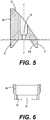
- the multi-legged yoke 8a is shown in greater detail in Fig. 5 which shows a view along section A- A in Fig. 3 .
- the multi-legged yoke 8a has a plurality of circumferentially spaced legs 31, termed "flutes".
- the flutes 31 are circumferentially spaced to permit the flow of fluid past the yoke 8a and to minimize the restriction of fluid flow.
- the flutes 31 are also circumferentially spaced to capture the sealing cap assembly 13 upon its release, as described further below.
- the radially inner edge 31a of each flute is angled about 50 degrees with respect to axis Y-Y. Each flute extends in the axial direction between 0.180 inch and 0.260 inch.
- the multi-legged yoke 8a has an angled edge 32 with respect to the axis Y-Y. In one embodiment, the angled edge 32 is angled about 40 degrees with respect to the horizontal axis X-X.
- the seat 14 for the glass bulb 11 is coaxial with the multi-legged yoke 8a and the seat 14 is intersected by the angled edge 32.
- the diameter of the multi-legged yoke 8a is about 0.934 inch and the diameter of the bulb seat 14 is about 0.156 inch.
- the overall axial dimension of the multi-legged yoke 8a is about 1 inch.
- Fig. 6 shows a detailed section view of the yoke support ring 8b along section B-B shown in Fig. 3 .
- the yoke support ring 8b has an overall axial dimension of about 0.370 inch and an outer diameter of 1.060 inch.
- the ring 8b has an annular flange 33 on which the multi-legged yoke 8a is supported.
- a notch 34 is formed on the output end of the yoke support ring 8b. The notch 34 facilitates use of a tool to thread the yoke support ring 8b with respect to the fitting 30 so as to compress the glass bulb 11 between the yoke 8a and the inlet seal assembly 13.
- a sliding, O-shaped collar 36 surrounds the glass bulb 11 between the angled edge 32 and the inlet seal cap assembly 13.
- the sliding collar 36 is connected to a collar rod 37 which extends axially in the outlet direction a predetermined distance past the flutes 31 of the yoke 8a.
- a physical stop 38 At its outlet end the collar rod 37 is terminated by a physical stop 38, which is constructed to interfere with the inlet biasing portion 4 during sprinkler activation.
- the collar rod 37 is constructed to transfer force to the collar 36 prior to sprinkler activation in order to break the glass bulb 11 so that the inlet seal cap assembly 13 can be released, as discussed further below.
- the inlet biasing portion 4 of the inlet 1 includes a first threaded tube 41, which houses an inlet compression spring 39 and a first spacer 40.
- the first threaded tube 41 has external threads at its inlet end which mate with internal threads of fitting 30.
- the first threaded tube 41 also has external threads that mate with internal threads of the inlet end 6 of flexible tube 3.
- the first spacer 40 has an outer annular flange 40a and an inner annular flange 40b axially spaced by a frustoconical web 40c.
- the inlet compression spring 39 is retained between an annular flange 41 a proximate the outlet end of the first threaded tube 41 and the outer annular flange of the first spacer 40.
- the first spacer 40 is biased axially by the inlet compression spring 39 towards the yoke support ring 8b.
- the web 40c has openings to permit fluid to pass therethrough.
- the inner annular flange 40b includes an opening though which the collar cable 37 passes.
- the optimum spring force is established when the first threaded tube 41 is fully threaded into the fitting 30 to set a desired distance between the inner annular flange 40b of the first spacer 40 and the stop 38 of the collar rod 37.
- the desired distance "Z" set is termed the "inlet stroke", and, in one embodiment, is set to be greater than the axial deflection that the end of the linkage 10 would make when the flexible tube 3 and the linkage 10 are bent into two opposing 90 degrees, i.e., folded in shallow Z- or S-shapes.
- the inlet stroke Z is approximately 0.60 inch.
- the flexible linkage 10 can be formed of wire or cable, such as braided stainless steel cable.
- the flexible linkage 10 is formed of a 0.125 inch diameter braided stainless steel cable.
- Collars 10a ( Fig. 2 ) and 10b ( Fig. 7 ) are attached, respectively, at the inlet and outlet ends of the flexible linkage 10, such as, for example, by crimping.
- the collar 10a interferes with inner annular flange 40b of the first spacer 40.
- the inlet end of the flexible linkage 10 extends axially through the center of the inner annular flange 40b and is thus radially spaced from the inner wall of the first threaded tube 41 of the inlet biasing portion 4.
- the flexible linkage 10 extends axially from the inlet biasing portion 4 through the flexible tube 3 to the outlet biasing portion 5 of the outlet 2.
- the outlet 2 includes the outlet biasing portion 5 and a sprinkler portion 42, which are connected together for example, by threaded connection.
- the outlet biasing portion 5 includes a second threaded tube 43 which houses an outlet compression spring 44, a second spacer 45 in contact with the outlet compression spring 44, and an orifice venturi 46 in contact with the second spacer 45.
- the second spacer 45 is constructed similarly to the first spacer 40.
- the second spacer 45 has an inner annular flange 45b connected to an outer annular flange 45a by a frustoconical web 45c, which includes at least one opening to permit fluid to pass through the web 45c.
- the outlet end of the flexible linkage 10 passes through a central opening in the inner annular flange 45b.
- the outlet compression spring 44 biases the inner annular flange 45b to contact the collar 10b attached to the linkage 10.
- the outlet compression spring 44 is retained between an annular retaining ring 47 and the outer annular flange 45a of the second spacer 45.
- the retaining ring 47 is retained in a notch 48 formed in the inner wall of the second threaded tube 43.
- the outlet compression spring 44 is retained by an annular flange similar to 41a of first threaded tube 41, shown in Fig. 2 .
- the outlet compression spring 44 biases the second spacer 45 in the outlet direction and into contact with a flange 46a of the orifice venturi 46.
- the orifice venturi 46 is supported by a sprinkler 42 of the outlet 2.
- the sprinkler 42 of the outlet 2 is generally arranged as a conventional fire sprinkler and includes a threaded sprinkler body 50 constructed to mate with threads of the outlet of the second tube 43 in biasing portion 5, a frame 51 extending from the body in the output direction, and a deflector 52 supported by the frame 51 at a hub 51a thereof.
- the deflector 52 is constructed to distribute fluid issuing from the outlet 2 through orifice venturi 46.
- the sprinkler body 50 retains an orifice plug 53 that communicates with outlet orifice 54 in the outlet end of the orifice venture 46.
- the orifice plug 53 is retained in a set position by an annular flange 50a shown in Fig.
- a thermally responsive element 56 such as, for example, a glass bulb filled with a thermally responsive fluid.
- a glass bulb having a nominal length of 20 mm, is used as the thermally responsive element 56.
- a set screw 55 in the hub 51a of the frame 51 is used to compress the glass bulb 56 against the orifice plug 53 to seat the plug 53 against the annular flange 50a.
- the orifice venturi 46 exerts a biasing force against the orifice plug 53.
- the distance ZZ between an outer flange 46a of the orifice venturi 46 and the inlet end of the body 50 of the sprinkler 42 is termed the outlet stroke ZZ, which is set by threading the body 50 with tube 43 of the outlet biasing portion 5.
- the outlet stroke ZZ is set to be about 0.80 inch and the inlet stroke Z is set as discussed above to be about 0.60 inch.
- the second threaded tube 43 has external threads at its inlet end for mating to internal threads of the flexible tube 3.
- the second threaded tube 43 also has internal threads for mating to the external threads of the sprinkler portion 42.
- the outlet 2 can be pre-assembled and attached as one modular unit to the outlet end 7 of the flexible tube 3.
- the flexible linkage 10 within the flexible tube 3 will also tend to deflect.
- the ends of the flexible linkage 10 within the tube 3 will change positions relative to the ends of the flexible tube 3.
- the ends of the linkage 10 will move longitudinally inward from the ends of the flexible tube 3 as the angular deflection of the flexible tube 3 increases.
- the inlet and outlet compression springs, 39 and 44 will tolerate changes in the relative movement between the flexible linkage 10 and the flexible tube 3 without affecting the tautness of the linkage 10 due to field induced bending of the flexible tube 3. Accordingly, the inlet compression spring 39 inlet stroke Z is set sufficiently large to avoid fracture of the glass bulb 11 due to bending of the flexible tube 3.
- the outlet compression spring 44 is constructed to be at least 1.5 times stronger than the opposing inlet compression spring 39 so that, as the flexible tube 3 is bent in a larger angle, the deflection of the ends of the linkage 10 is compensated for by the inlet compression spring 39 and not by the outlet compression spring 44.
- the thermally responsive element i.e., the bulb 56
- the thermally responsive element is a glass bulb filled with a thermally responsive fluid, as shown in Fig. 7
- a temperature rise above a predetermined limit associated with the bulb 56 will cause the bulb 56 to rupture.
- the compression on the orifice plug 53, and the force exerted by the outlet compression spring 44 on the orifice venturi 46 will also urge the orifice plug 53 in an outlet direction out of the outlet orifice 54, and the plug 53 will be ejected.
- the force exerted on the orifice venturi 46 by the outlet compression spring 44 forces the second spacer 45 and the linkage 10 to move from a first, inactivated position, through the outlet stroke into a second, activated position where the orifice venturi slides axially in the outlet direction until it is wedged into a frustoconical surface 50b formed in the body 50 of the sprinkler 42.
- the second spacer 45 As the second spacer 45 moves to the second position, it pulls on the crimp 10b which in turn pulls on the first spacer 40 which compresses the inlet compression spring 39.
- the first spacer 40 continues to translate axially in the output direction causing the first spacer 40 to pull on the collar rod stop 38.
- the rod 37 When the collar rod 37 is pulled from the stop 38 by the first spacer 40, the rod 37 pulls on the collar 36 in a direction down the angled edge 32 of the yoke 8, which, in turn, rapidly snaps the collar 36 into the bulb 11, thereby breaking the bulb 11.
- the collar rod 37 is constructed to engage the first spacer 40 when the first spacer 40 is displaced axially the stroke distance Z of 0.60 inch and the second spacer 45 is displaced axially a predetermined outlet stroke distance ZZ of 0.80 inch.
- the 0.20 inch difference between the inlet and outlet stroke distances represents a safety margin over the 0.60 inch shift of the taut flexible linkage 10 would experience merely by being bent to suit field installation.
- the inlet seal cap assembly 13 moves axially in the output direction, pivots on the pivot point 11b, and slides down the angled edge 32 of the yoke 8, whereupon the inlet seal cap assembly 13 is retained by the flutes 31 of the yoke 8.
- Fluid from the sprinkler system flows through the inlet orifice 12, around the retained inlet seal cap assembly 13, through the interior of the flexible tube 3 and out the outlet orifice 54 of the outlet 2 to the deflector 52, whereupon the fluid is distributed from the sprinkler 100.
- Another aspect of the invention is a fire protection system utilizing one or more such dry sprinklers.
- the system includes a fluid supply in communication with at least one dry fire protection sprinkler.
- At least one of the dry fire protection sprinklers of the fire protection system is constructed as a flexible dry sprinkler in accordance with the foregoing description.
Landscapes
- Health & Medical Sciences (AREA)
- Public Health (AREA)
- Business, Economics & Management (AREA)
- Emergency Management (AREA)
- Fire-Extinguishing By Fire Departments, And Fire-Extinguishing Equipment And Control Thereof (AREA)
- Nozzles (AREA)
Applications Claiming Priority (3)
| Application Number | Priority Date | Filing Date | Title |
|---|---|---|---|
| US13/486,904 US8887822B2 (en) | 2012-06-01 | 2012-06-01 | Flexible dry sprinklers |
| EP13797211.3A EP2854957B1 (de) | 2012-06-01 | 2013-05-30 | Flexible trockensprinkler |
| PCT/US2013/043298 WO2013181357A2 (en) | 2012-06-01 | 2013-05-30 | Flexible dry sprinklers |
Related Parent Applications (1)
| Application Number | Title | Priority Date | Filing Date |
|---|---|---|---|
| EP13797211.3A Division EP2854957B1 (de) | 2012-06-01 | 2013-05-30 | Flexible trockensprinkler |
Publications (2)
| Publication Number | Publication Date |
|---|---|
| EP3662975A2 true EP3662975A2 (de) | 2020-06-10 |
| EP3662975A3 EP3662975A3 (de) | 2020-06-17 |
Family
ID=49668848
Family Applications (2)
| Application Number | Title | Priority Date | Filing Date |
|---|---|---|---|
| EP19207309.6A Pending EP3662975A3 (de) | 2012-06-01 | 2013-05-30 | Flexible trockensprinkler |
| EP13797211.3A Active EP2854957B1 (de) | 2012-06-01 | 2013-05-30 | Flexible trockensprinkler |
Family Applications After (1)
| Application Number | Title | Priority Date | Filing Date |
|---|---|---|---|
| EP13797211.3A Active EP2854957B1 (de) | 2012-06-01 | 2013-05-30 | Flexible trockensprinkler |
Country Status (8)
| Country | Link |
|---|---|
| US (10) | US8887822B2 (de) |
| EP (2) | EP3662975A3 (de) |
| CN (1) | CN104487142B (de) |
| AU (1) | AU2013267363B2 (de) |
| BR (1) | BR112014029843A2 (de) |
| CA (1) | CA2875122C (de) |
| MX (3) | MX351553B (de) |
| WO (1) | WO2013181357A2 (de) |
Families Citing this family (16)
| Publication number | Priority date | Publication date | Assignee | Title |
|---|---|---|---|---|
| US9358411B2 (en) | 2011-05-27 | 2016-06-07 | Victaulic Company | Flexible dry sprinkler |
| US8887822B2 (en) | 2012-06-01 | 2014-11-18 | Reliable Automatic Sprinkler Co., Inc. | Flexible dry sprinklers |
| US9415250B2 (en) * | 2012-12-20 | 2016-08-16 | Victaulic Company | Dry sprinkler |
| US10646736B2 (en) | 2015-07-28 | 2020-05-12 | Victaulic Company | Preaction sprinkler valve assemblies, related dry sprinkler devices adapted for long travel, and fire protection sprinkler systems |
| KR102687803B1 (ko) | 2015-07-28 | 2024-07-24 | 글로브 파이어 스프링클러 코포레이션 | 사전작용 스프링클러 밸브 조립체 |
| DE202015103950U1 (de) * | 2015-07-28 | 2016-11-02 | Job Lizenz Gmbh & Co. Kg | Thermisches Auslöseelement |
| WO2017083810A1 (en) * | 2015-11-11 | 2017-05-18 | The Reliable Automatic Sprinkler Co. | Dry sprinkler |
| US20170165511A1 (en) * | 2015-12-15 | 2017-06-15 | Globe Fire Sprinkler Corporation | Fire protection systems and methods for attic/combustible concealed spaces beneath pitched roofs using preaction sprinkler valve assemblies and related dry sprinkler devices |
| US10850144B2 (en) * | 2017-06-14 | 2020-12-01 | Victaulic Company | Preaction sprinkler valve assemblies, related dry sprinkler devices, and compressive activation mechanism |
| EP3651866B1 (de) * | 2017-07-13 | 2022-02-09 | Victaulic Company | Sprinklervorbetätigungsventilanordnung, zugehörige trockensprinklervorrichtungen für brandschutz-sprinklersysteme mit grosser reichweite |
| US11045675B2 (en) | 2018-02-02 | 2021-06-29 | Victaulic Company | Belleville seal for valve seat having a tear drop laminar flow feature |
| CN111017222B (zh) * | 2019-12-13 | 2021-08-06 | 温州职业技术学院 | 一种用于高层建筑灭火的无人机 |
| US20230241439A1 (en) * | 2020-08-21 | 2023-08-03 | Engineered Corrosion Solutions, Llc | Nozzle plugs for a deluge fire protection system |
| EP4304742A1 (de) | 2021-03-08 | 2024-01-17 | Tyco Fire Products LP | Systeme und verfahren für sprinklersysteme mit flexiblem schlauch und schnelldichtungsadapter |
| CN223601915U (zh) | 2022-05-01 | 2025-11-28 | 米尼麦克斯维京专利管理有限公司 | 自动干式喷洒器组件 |
| CN115425342A (zh) * | 2022-09-23 | 2022-12-02 | 江苏正力新能电池技术有限公司 | 一种电池安全结构及电池 |
Citations (1)
| Publication number | Priority date | Publication date | Assignee | Title |
|---|---|---|---|---|
| US5775431A (en) | 1996-09-11 | 1998-07-07 | The Reliable Automatic Sprinkler Co., Inc. | Dry sprinkler arrangements |
Family Cites Families (75)
| Publication number | Priority date | Publication date | Assignee | Title |
|---|---|---|---|---|
| US3007528A (en) | 1959-07-17 | 1961-11-07 | Star Sprinkler Corp | Dry pendant sprinklers |
| US3135331A (en) * | 1962-09-24 | 1964-06-02 | Floyd J Lee | Dry adapter for fire-extinguishing sprinkler systems |
| US3857277A (en) | 1972-12-29 | 1974-12-31 | Laval Turbine | Flow indicator |
| GB1582360A (en) * | 1977-04-02 | 1981-01-07 | Angus Fire Armour Ltd | Fire extinguishant sprinklers |
| GB1564662A (en) | 1977-06-15 | 1980-04-10 | Mather & Platt Ltd | Sprinkler arrangements |
| DE3223154A1 (de) | 1982-06-22 | 1983-12-22 | Verband der Sachversicherer e.V., 5000 Köln | Laengenverstellbarer trockensprinkler |
| US4570719A (en) | 1984-06-01 | 1986-02-18 | Grinnell Fire Protection Systems Company, Inc. | Dry pipe valve accelerator |
| US4854388A (en) * | 1987-05-28 | 1989-08-08 | American Safety Products | Fire extinguishing apparatus |
| US4930579A (en) | 1988-02-18 | 1990-06-05 | Gary George | Fire extinguishing device for the home heating plant utilizing an existing spigot as the water source |
| US5154232A (en) | 1988-09-21 | 1992-10-13 | Back-Flo Alarm Valve Co., Inc. | Combined alarm and back-flow prevention arrangement for fire suppression sprinkler system |
| US5297635A (en) | 1988-09-21 | 1994-03-29 | Back-Flo Alarm Valve Co., Inc. | Combined alarm and back-flow prevention arrangement for fire suppression sprinkler system |
| US4991655A (en) | 1988-11-10 | 1991-02-12 | Back-Flo Alarm Valve Co., Inc. | Combined alarm and back-flow prevention arrangement for fire suppression sprinkler system |
| US4964470A (en) | 1988-11-10 | 1990-10-23 | Mcdonald Plumbing & Heating Inc. | Sprinkler connection to scrubber duct |
| DE3919638C1 (en) | 1989-06-16 | 1990-11-29 | Witzenmann Gmbh, Metallschlauch-Fabrik Pforzheim, 7530 Pforzheim, De | Fire protection sprinkler system - has nozzles connected to main water line by flexible hoses |
| JPH07114819B2 (ja) * | 1990-04-23 | 1995-12-13 | 五十鈴工業株式会社 | スプリンクラーヘッド取付用配管の施工方法とスプリンクラーヘッド取付用配管構造 |
| DE4122665A1 (de) | 1991-07-09 | 1993-01-14 | Total Feuerschutz Gmbh | Sprinkler fuer selbsttaetige feuerloeschanlagen |
| JP2632615B2 (ja) | 1991-11-18 | 1997-07-23 | 株式会社西原衛生工業所大阪店 | スプリンクラー用巻出し管 |
| JPH06170008A (ja) | 1992-08-11 | 1994-06-21 | Bosai Kikaku:Kk | 消火スプリンクラー配管構造 |
| US5570745A (en) | 1995-05-31 | 1996-11-05 | Pnm, Inc. | Relocatable sprinkler assemblage |
| US5842526A (en) * | 1995-09-26 | 1998-12-01 | Archer; Robert C. | Sprinkler head mounting system |
| JP3852056B2 (ja) | 1996-04-10 | 2006-11-29 | ホーチキ株式会社 | スプリンクラー消火設備の巻出し配管支持構造 |
| US6336509B1 (en) * | 1997-03-07 | 2002-01-08 | Central Sprinkler Corporation | Low pressure fast response bulb sprinklers |
| US6076608A (en) | 1998-05-11 | 2000-06-20 | Pnm, Inc. | Fire-suppression sprinkler system and method for installation and retrofit |
| KR200217901Y1 (ko) | 1998-07-18 | 2001-06-01 | 대명기계공업주식회사 | 스프링클러의 링너트 유동방지구조 |
| US6123154A (en) | 1999-01-08 | 2000-09-26 | Pnm, Inc. | Support system attachment mechanism for fire protection sprinklers |
| US6119784A (en) | 1999-01-08 | 2000-09-19 | Pnm, Inc. | Support system for fire protection sprinklers |
| US6488097B1 (en) | 1999-01-08 | 2002-12-03 | Pnm, Inc. | Fire protection sprinkler head support |
| DE19914022A1 (de) | 1999-03-19 | 2000-09-28 | Feuerschutz G Knopf Gmbh | Vorrichtung zum Ansaugen von Wasser aus offenen Gewässern |
| US6164324A (en) | 1999-09-23 | 2000-12-26 | Edward Vogt Valve Company | Adjustable quick closing disk check value with flow indicator |
| US6158519A (en) | 2000-01-18 | 2000-12-12 | Kretschmer; Alan P. | Fire suppression method and apparatus |
| AU2665601A (en) * | 2000-01-24 | 2001-08-07 | Gw Sprinkler A/S | Sprinkler head with a double deflector arrangement |
| KR200191235Y1 (ko) | 2000-03-11 | 2000-08-16 | 장재익 | 스프링클러용 배관 결합구조 |
| US6536533B2 (en) * | 2000-03-27 | 2003-03-25 | Victaulic Company Of America | Low pressure actuator for dry sprinkler system |
| US6851482B2 (en) | 2000-11-02 | 2005-02-08 | Kevin Michael Dolan | Sprinkler assembly |
| US6860331B2 (en) | 2001-02-09 | 2005-03-01 | Potter Electric Signal Company | Single-piece manifold |
| US6491109B2 (en) | 2001-05-11 | 2002-12-10 | Joel P. Christenson | Kinetic antifreeze device |
| DE10137968A1 (de) | 2001-08-08 | 2003-03-06 | Roehm Gmbh | Depot-Polymerisationsstarter-Perlen |
| US6526907B1 (en) | 2001-08-20 | 2003-03-04 | Wade L. Donehue | View around flow indicator |
| JP4872054B2 (ja) | 2001-09-11 | 2012-02-08 | 丸一株式会社 | 遠隔操作式排水栓装置 |
| KR200285117Y1 (ko) | 2001-10-16 | 2002-08-13 | 박화자 | 소방용 스프링클러헤드 고정부재 |
| US20030075343A1 (en) | 2001-10-22 | 2003-04-24 | National Foam, Inc., D/B/A Kidde Fire Fighting | Dry sprinkler |
| US7143834B2 (en) | 2001-11-01 | 2006-12-05 | Kevin Michael Dolan | Sprinkler assembly |
| US6871660B2 (en) | 2002-06-19 | 2005-03-29 | Bioanalytical Systems, Inc. | Pinch valve and method of operating same |
| US7516800B1 (en) * | 2002-07-19 | 2009-04-14 | Tyco Fire Products Lp | Dry sprinkler |
| US8327946B1 (en) * | 2002-07-19 | 2012-12-11 | Tyco Fire Products Lp | Dry sprinkler |
| US6907938B2 (en) | 2002-08-07 | 2005-06-21 | Pbj, Llc | Decorative support panel |
| JP2005027769A (ja) | 2003-07-09 | 2005-02-03 | Hitachi Metals Ltd | スプリンクラー用フレキユニット |
| US7213319B2 (en) | 2004-11-29 | 2007-05-08 | Tyco Fire Products Lp | Method of installing a dry sprinkler installation |
| US7559376B2 (en) | 2004-12-01 | 2009-07-14 | Tyco Fire Products Lp | Dry sprinkler with a diverter seal assembly |
| KR200384965Y1 (ko) | 2005-01-13 | 2005-05-24 | 전태익 | 스프링클러의 배관용 분배접속관 |
| US7293576B2 (en) | 2005-03-28 | 2007-11-13 | Potter Electric Signal Company | Single-piece manifold with reduced pressure arrangement |
| US7766252B2 (en) * | 2006-02-15 | 2010-08-03 | The Viking Corporation | Dry sprinkler assembly |
| US7373720B1 (en) | 2006-03-20 | 2008-05-20 | Jensen Raymond H | Fire sprinkler flexible piping system, bracing apparatus therefor, and method of installing a fire sprinkler |
| US7841418B2 (en) * | 2006-04-21 | 2010-11-30 | The Reliable Automatic Sprinkler Co., Inc. | Extended coverage horizontal sidewall sprinkler |
| US7644736B2 (en) * | 2006-05-26 | 2010-01-12 | Rehau, Inc. | PEX pipe for high pressure and high temperature applications |
| KR20070059890A (ko) | 2006-07-14 | 2007-06-12 | 박춘경 | 소화배관용 높이조절장치 |
| US8607888B2 (en) | 2007-02-16 | 2013-12-17 | Michael Jay Nusbaum | Self-contained automatic fire extinguisher |
| US7845599B2 (en) | 2007-03-22 | 2010-12-07 | The Viking Corporation | Mounting coupling for sprinkler support system |
| US7699117B2 (en) | 2007-05-09 | 2010-04-20 | The Wanda Group | Fire protection sprinkler system and related apparatus |
| DE102007062668A1 (de) | 2007-12-24 | 2009-06-25 | Peter Fuchs | Vorrichtung - ausgebildet als Sicherheitskomponente in Rohrsystemen von Anlagen - insbesondere Sprinkleranlagen - gegen Beschädigung durch Anstoßkontakt |
| GB0803357D0 (en) * | 2008-02-25 | 2008-04-02 | Building Res Establishment Ltd | Dry pipe sprinkler system |
| US7921928B2 (en) * | 2008-08-18 | 2011-04-12 | The Viking Corporation | 90 degree dry horizontal sidewall sprinkler |
| CN201356932Y (zh) | 2009-03-06 | 2009-12-09 | 武汉绿色消防器材有限公司 | 一种烟道灭火装置 |
| JP4903834B2 (ja) | 2009-04-27 | 2012-03-28 | 株式会社日立製作所 | 利得可変増幅回路及びそれを用いた無線通信機器用の集積回路 |
| KR101128257B1 (ko) | 2009-07-31 | 2012-03-23 | 김봉이 | 아파트용 엘보 일체형 플렉시블 조인트 스프링클러 장치 |
| WO2011031722A1 (en) * | 2009-09-11 | 2011-03-17 | Victaulic Company | Flexible assembly for sprinklers |
| KR101130578B1 (ko) | 2009-10-22 | 2012-04-16 | 승진산업 (주) | 배관 헤드용 플렉시블 튜브의 연결구 |
| US8272615B2 (en) | 2010-05-20 | 2012-09-25 | Flexhead Industries, Inc. | Hub with locking mechanism |
| US8740158B2 (en) | 2010-06-25 | 2014-06-03 | Flexhead Industries, Inc. | Hat channel adaptor for sprinkler support assembly |
| US20120132444A1 (en) | 2010-11-29 | 2012-05-31 | Cappy's Concepts Llc | Dry Sprinkler head |
| KR101114864B1 (ko) | 2011-05-20 | 2012-03-06 | 이큐조인텍 주식회사 | 소방용 배관 어댑터 및 그 제조방법 |
| US9358411B2 (en) | 2011-05-27 | 2016-06-07 | Victaulic Company | Flexible dry sprinkler |
| US9339673B2 (en) * | 2011-05-27 | 2016-05-17 | Victaulic Company | Flexible dry sprinkler |
| JP5639958B2 (ja) | 2011-05-27 | 2014-12-10 | 日東電工株式会社 | 半導体ウエハマウント方法および半導体ウエハマウント装置 |
| US8887822B2 (en) * | 2012-06-01 | 2014-11-18 | Reliable Automatic Sprinkler Co., Inc. | Flexible dry sprinklers |
-
2012
- 2012-06-01 US US13/486,904 patent/US8887822B2/en active Active - Reinstated
-
2013
- 2013-05-30 BR BR112014029843A patent/BR112014029843A2/pt not_active Application Discontinuation
- 2013-05-30 CA CA2875122A patent/CA2875122C/en not_active Expired - Fee Related
- 2013-05-30 CN CN201380037288.3A patent/CN104487142B/zh active Active
- 2013-05-30 WO PCT/US2013/043298 patent/WO2013181357A2/en not_active Ceased
- 2013-05-30 AU AU2013267363A patent/AU2013267363B2/en not_active Ceased
- 2013-05-30 EP EP19207309.6A patent/EP3662975A3/de active Pending
- 2013-05-30 MX MX2014014591A patent/MX351553B/es active IP Right Grant
- 2013-05-30 EP EP13797211.3A patent/EP2854957B1/de active Active
-
2014
- 2014-11-06 US US14/534,881 patent/US10265560B2/en active Active
- 2014-11-28 MX MX2022013107A patent/MX2022013107A/es unknown
- 2014-11-28 MX MX2022013108A patent/MX2022013108A/es unknown
-
2018
- 2018-06-01 US US15/995,297 patent/US10335621B2/en active Active
- 2018-07-25 US US16/044,837 patent/US10493307B2/en active Active
- 2018-07-25 US US16/044,855 patent/US10391343B2/en active Active
-
2019
- 2019-07-18 US US16/515,600 patent/US10933267B2/en active Active
-
2021
- 2021-01-14 US US17/149,178 patent/US11596822B2/en active Active
-
2023
- 2023-02-08 US US18/166,042 patent/US11872427B2/en active Active
- 2023-11-17 US US18/512,168 patent/US12201863B2/en active Active
-
2024
- 2024-12-30 US US19/004,623 patent/US20250135252A1/en active Pending
Patent Citations (2)
| Publication number | Priority date | Publication date | Assignee | Title |
|---|---|---|---|---|
| US5775431A (en) | 1996-09-11 | 1998-07-07 | The Reliable Automatic Sprinkler Co., Inc. | Dry sprinkler arrangements |
| US5967240A (en) | 1996-09-11 | 1999-10-19 | The Reliable Automatic Sprinkler, Co. Inc. | Dry sprinkler arrangements |
Also Published As
Similar Documents
| Publication | Publication Date | Title |
|---|---|---|
| US12201863B2 (en) | Flexible dry sprinkler | |
| US12397185B2 (en) | Flexible dry sprinkler having a differential pressure controller | |
| US20250195930A1 (en) | Dry sprinkler | |
| HK1187847A (en) | Flexible dry sprinklers |
Legal Events
| Date | Code | Title | Description |
|---|---|---|---|
| STAA | Information on the status of an ep patent application or granted ep patent |
Free format text: STATUS: UNKNOWN |
|
| PUAI | Public reference made under article 153(3) epc to a published international application that has entered the european phase |
Free format text: ORIGINAL CODE: 0009012 |
|
| STAA | Information on the status of an ep patent application or granted ep patent |
Free format text: STATUS: THE APPLICATION HAS BEEN PUBLISHED |
|
| PUAL | Search report despatched |
Free format text: ORIGINAL CODE: 0009013 |
|
| AC | Divisional application: reference to earlier application |
Ref document number: 2854957 Country of ref document: EP Kind code of ref document: P |
|
| AK | Designated contracting states |
Kind code of ref document: A2 Designated state(s): AL AT BE BG CH CY CZ DE DK EE ES FI FR GB GR HR HU IE IS IT LI LT LU LV MC MK MT NL NO PL PT RO RS SE SI SK SM TR |
|
| AK | Designated contracting states |
Kind code of ref document: A3 Designated state(s): AL AT BE BG CH CY CZ DE DK EE ES FI FR GB GR HR HU IE IS IT LI LT LU LV MC MK MT NL NO PL PT RO RS SE SI SK SM TR |
|
| RIC1 | Information provided on ipc code assigned before grant |
Ipc: A62C 35/62 20060101AFI20200512BHEP Ipc: A62C 37/42 20060101ALI20200512BHEP Ipc: A62C 31/02 20060101ALI20200512BHEP Ipc: A62C 37/14 20060101ALI20200512BHEP |
|
| STAA | Information on the status of an ep patent application or granted ep patent |
Free format text: STATUS: REQUEST FOR EXAMINATION WAS MADE |
|
| 17P | Request for examination filed |
Effective date: 20201114 |
|
| RBV | Designated contracting states (corrected) |
Designated state(s): AL AT BE BG CH CY CZ DE DK EE ES FI FR GB GR HR HU IE IS IT LI LT LU LV MC MK MT NL NO PL PT RO RS SE SI SK SM TR |
|
| STAA | Information on the status of an ep patent application or granted ep patent |
Free format text: STATUS: EXAMINATION IS IN PROGRESS |
|
| 17Q | First examination report despatched |
Effective date: 20230314 |
|
| GRAP | Despatch of communication of intention to grant a patent |
Free format text: ORIGINAL CODE: EPIDOSNIGR1 |
|
| STAA | Information on the status of an ep patent application or granted ep patent |
Free format text: STATUS: GRANT OF PATENT IS INTENDED |