EP3662732B1 - Landwirtschaftliche maschine zur ausbringung von körnigen feststoffen mit einem pneumatischen fördersystem - Google Patents
Landwirtschaftliche maschine zur ausbringung von körnigen feststoffen mit einem pneumatischen fördersystem Download PDFInfo
- Publication number
- EP3662732B1 EP3662732B1 EP19212693.6A EP19212693A EP3662732B1 EP 3662732 B1 EP3662732 B1 EP 3662732B1 EP 19212693 A EP19212693 A EP 19212693A EP 3662732 B1 EP3662732 B1 EP 3662732B1
- Authority
- EP
- European Patent Office
- Prior art keywords
- outlet openings
- distribution chamber
- agricultural machine
- lines
- solids
- Prior art date
- Legal status (The legal status is an assumption and is not a legal conclusion. Google has not performed a legal analysis and makes no representation as to the accuracy of the status listed.)
- Active
Links
Images


Classifications
-
- A—HUMAN NECESSITIES
- A01—AGRICULTURE; FORESTRY; ANIMAL HUSBANDRY; HUNTING; TRAPPING; FISHING
- A01C—PLANTING; SOWING; FERTILISING
- A01C7/00—Sowing
- A01C7/08—Broadcast seeders; Seeders depositing seeds in rows
- A01C7/081—Seeders depositing seeds in rows using pneumatic means
- A01C7/084—Pneumatic distribution heads for seeders
-
- A—HUMAN NECESSITIES
- A01—AGRICULTURE; FORESTRY; ANIMAL HUSBANDRY; HUNTING; TRAPPING; FISHING
- A01C—PLANTING; SOWING; FERTILISING
- A01C7/00—Sowing
- A01C7/08—Broadcast seeders; Seeders depositing seeds in rows
- A01C7/10—Devices for adjusting the seed-box ; Regulation of machines for depositing quantities at intervals
- A01C7/102—Regulating or controlling the seed rate
- A01C7/105—Seed sensors
Definitions
- the present invention relates to an agricultural machine for spreading granular solids with a pneumatic conveying system for conveying the granular solids from a storage tank to a number of delivery units, the conveying system having a fan, a connecting line from the tank to a distribution device which has a distribution chamber has a number of outlet openings formed therein, and a number of lines which are each connected to an associated outlet opening and which conduct the solids conveyed by the air flow to an output unit assigned to the line, each outlet opening having a sector of an outer wall of the distribution chamber with a respective one Sector size is assigned and the sectors assigned to the outlet openings occupy different proportions of the total of the sectors formed in the distribution chamber.
- a machine with a distribution device is from the document DE 195 42 057 A1 known. It has been found that, despite the uniform arrangement of the outlet openings with identical proportions of each outlet opening on the outer wall of the distribution chamber, the solids are not evenly distributed over the outlet openings.
- a distribution chamber is arranged in a housing, from which the granular solids are distributed in connected sub-lines.
- Several sub-lines each open into a common multiple mouthpiece arranged downstream. From there, the granular solids are fed to the assigned drill coulters in a respective outlet line connected to the multiple mouthpiece.
- the inflow of solids provided for a drill coulter is therefore initially divided into several partial material flows from the distribution chamber in order to bring these partial material flows back together in a multiple mouth piece downstream of the distribution chamber.
- In the distribution chamber there are circular sectors of different sizes, which differ from one another in terms of a different arc portion. It is not explained in more detail why which sub-lines could be assigned to a certain sector of the circle. Partial lines that are not required are closed. The number of connected partial lines can be varied depending on the application, but it is left to chance which circular sectors are assigned to the partial lines and which of these are assigned to a multiple mouthpiece.
- the object is achieved for a generic machine in that lines that are connected to outlet openings, the associated sector size of which is larger than the sector size of other outlet openings, have a higher dynamic pressure in the connection area to the outlet opening than lines that are connected to outlet openings, the associated sector size of which is smaller than the sector size of other outlet openings.
- the lines connected to the outlet openings have different back pressures.
- the different back pressures result from different lengths of the at the respective outlet openings connected lines, different bending radii in which the lines are guided in bends and bends, an upward or downward line course and other influencing factors on the dynamic pressure in a line. If the air flow flowing into the distribution chamber encounters different dynamic pressures in the outlet openings, the air flow tends to flow preferentially into those outlet openings which have a lower dynamic pressure when the outlet openings are of the same size. As a result, a smaller amount of the air flow flows into the outlet openings with a higher dynamic pressure, and these outlet openings are therefore only charged with a smaller amount of solids than the outlet openings with a lower dynamic pressure. Despite the openings of the outlet openings of the same size, there are thus different throughput quantities of solids.
- the different back pressures in the outlet openings and the resulting different throughput quantities with solids can be at least partially or completely compensated for by the now different sector sizes of the outlet openings. Since the lines with a higher dynamic pressure are connected to outlet openings with a relatively larger sector size, these outlet openings can now accommodate at least approximately the same throughput of solids due to the larger dimensioning, despite the smaller inflow volume for the same size as the outlet openings whose lines connected to them have a lower dynamic pressure .
- sector size does not mean the cross-sectional area of the outlet opening, but the proportion that a sector has in the sum of all sectors in the distribution area over which the granular solids in the distribution chamber are allocated to the respective outlet openings.
- the distribution areas of individual sectors do not have to have a smooth surface, but can have a spatial design that sensibly supports the division of the material flow of the granular solids and the air flow, such as funnel-like designs.
- the sectors can be separated from one another by ribs, webs, formations such as elevations and depressions in the guide surfaces of the distribution chamber and the like.
- the sector sizes can result, for example, from proportions of circular arcs within which granular solids are only fed to one associated outlet opening.
- the distribution chamber has a circular basic shape.
- uniform flow conditions result, which improve the uniform distribution of the granular solids.
- the respective proportions of the outlet openings in the sum of the sectors formed in the distribution chamber result from different circular arc proportions of guide surfaces that are allocated to the respective outlet openings and / or from differently sized cross-sectional areas of the outlet openings in the distribution chamber.
- the outlet openings are designed so differently in size that there are different inflow quantities of the granular solids per unit of a cross-sectional area at the outlet openings and the quantity differentiation is thus only controlled by the size of the outlet openings, or whether the outlet openings are designed exactly or at least approximately the same size and the size of the guide surface associated with a respective outlet opening is designed differently, or whether a combination of these possibilities is selected to at least approximately the same or exactly the same inflow into a To achieve the outlet opening despite different back pressure in the lines connected to the outlet openings.
- the amount of granular solids flowing into an outlet opening in the distribution chamber is so differentiated, despite different dynamic pressures in the lines connected to the outlet openings, by varying the size of the outlet openings and / or the sector proportions on the guide surfaces that they are nevertheless the same or at least approximately results in the same distribution amount for each outlet opening.
- the connecting line has an at least approximately vertical orientation in the area of the opening into the distribution chamber, so that it introduces the granular solids into the distribution chamber from an at least approximately vertical direction; the granular solids are conveyed centrally into the distribution chamber, and guide surfaces are formed in the distribution chamber with which the solids are diverted from the at least approximately vertical direction into an at least approximately horizontal and radial direction towards the outlet openings. Due to the central inflow of the granular solids into the distribution chamber from a vertical direction and the distribution of the granular solids in a horizontal radial direction outwards, the gravitational forces act on the granular solids evenly and regardless of the outlet opening to which the granular solids are transported by the air flow will. A distribution error effect that could result from gravitational forces acting differently on different parts of the crop flow is thereby eliminated.
- the distribution chamber has between 3 and 48 outlet openings. Depending on how many outlet openings the distribution chamber has, the differences between the individual outlet openings associated sector sizes can be differentiated to different degrees.
- the working width of the agricultural machine also has an influence on how strongly the respective sector sizes differ from one another. With a working width of 3 m, for example, there are smaller differences in dynamic pressure from the length of the respective line to a central and an outer seed coulter than with a working width of 12 m, for example. In one case, the line length difference is approx. 1.5 m, in the other Case approx. 6 m.
- the greater the difference in line length in an agricultural machine the more intermediate stages in the sector sizes can be formed between the largest and smallest sector sizes in order to achieve approximately or exactly the same distribution across the width of the agricultural machine in the distribution chamber despite different back pressures to achieve.
- the distribution chamber is delimited circumferentially over the height of the outlet openings by two annular shaped bodies, which are separated from one another by an at least approximately horizontal dividing line, and both shaped bodies have mutually matching formations that each form an outlet opening in pairs.
- the two ring-shaped molded bodies are easy to manufacture and assemble as cast parts made of a metallic, ceramic material or a plastic.
- the distribution chamber is easily accessible from above for maintenance or repairs if only the upper annular shaped body is dismantled.
- the guide surfaces, via which the granular solids are fed to the respective outlet openings, can easily be modeled into the tools for the molded bodies.
- the outlet openings are marked on the outwardly facing side of the outer wall by an identifying mark. Maintenance and repair work is made easier if it is immediately recognizable from the marking which sector size a respective outlet opening has.
- the marking can be designed to be permanent, for example by being designed as a depression and / or elevation in the outwardly facing surface of the housing of the outlet opening.
- movable separating webs are arranged between adjacent outlet openings, the spatial position of which can be adjusted manually and / or by motor. Subsequent fine adjustment of the sector sizes is possible using movable dividers.
- the agricultural machine can be adapted to different conveying behavior of different granular solids and / or to wear or material build-up within the distribution chamber via the separating webs. It is conceivable to recommend certain positioning positions of the separating webs for certain granular solids in order to optimally adjust the agricultural machine to the respective solids.
- sensors connected to evaluation electronics are arranged at the outlet openings, the lines and / or the output units, with which the amount of granular solids transported in a single line is determined; the evaluation electronics show the determined amounts of the individual lines and differences in amount on and / or compares these and / or outputs control signals to an actuator with which the separators can be adjusted.
- the adjustment of the dividers can also be done automatically with this equipment of the agricultural machine if the agricultural machine is equipped with a sensor system that distributes the measures granular solids on the individual outlet openings, and a control is available with which the determined sensor values are converted into adjusting movements of the separating webs via suitable actuators.
- solutions are also possible that can only be controlled remotely or that can be adjusted by a motor on the agricultural machine itself.
- throttle elements are arranged on outlet openings, lines and / or output units, by means of which the dynamic pressure in the relevant line is increased.
- the back pressure in the respective lines can also be changed in a targeted manner using throttle elements, so that the back pressure in the individual lines is at a level at which approximately the same distribution quantities result in the respective outlet openings.
- the throttle elements are used in the components for the lines in which there is less dynamic pressure than in other lines.
- the throttle elements can in particular be used to make a fine adjustment of the distribution quantities.
- the throttle elements are designed to be movable and / or volumetrically variable and their spatial position and / or volume shape can be adjusted manually and / or by a motor.
- any intermediate level is possible between fully automatic and only manual adjustment, depending on the effort involved.
- sensors connected to evaluation electronics are arranged on the outlet openings, the lines and / or the output units, with which the quantity conveyed in an individual line of granular solids is determined, the evaluation electronics compares the determined quantity values of the individual lines and shows quantity differences and / or outputs control signals to an actuator system with which the throttle elements are movable and / or volumetrically variable.
- the proposed sensor system enables fully automatic regulation of the throttle elements.
- a sketch of an agricultural machine 2 is shown, the agricultural machine being a seed drill.
- a storage tank 4 there is seed as an example of granular solids, which are pneumatically conveyed from the storage tank 4 to a number of delivery units.
- the granular solids are carried with the air flow that the fan 6 generates.
- the air flow conveys the granular solids via the connecting line 8 to the distribution device 10.
- the distribution device 10 there is a distribution chamber 12 in which the granular solids are distributed to a number of outlet openings 14. Lines 16, via which the granular solids are conveyed to the dispensing units, are connected to each of the outlet openings 14.
- the delivery units can be, for example, a seed coulter.
- the granular solids are moved by the air stream at flow speeds of up to 30 m / s.
- the distribution device 10 is aligned approximately horizontally with respect to the connecting line 8 protruding in the vertical direction. From the connecting line 8, the granular solids are deflected in a movement path by approximately 90 °, in order then to enter the lines 16 from the outlet openings 14. When the granular solids are deflected in the distribution chamber 12, they are assigned to the respective outlet openings 14 through which they leave the distribution chamber 12.
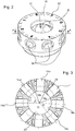
- Fig. 2 is a view obliquely from above of a distribution device 10 without an upper cover.
- the distribution device 10 has an annular shape.
- the outlet openings 14 are designed so that the lines 16 can be connected to them on the outside.
- Each outlet opening 14 is assigned a sector from which the granular solids located there run into the associated outlet opening 14.
- the distribution chamber 12 has surfaces via which the granular solids are fed to the outlet openings 14. These surfaces form guide surfaces 20.
- the markings 22, with which the individual outlet openings 14 are identified can be seen in the view obliquely from above on the distribution device 10 shown.
- FIG. 13 is a top view of the lower molding of FIG Fig. 2 Distribution device 10 shown with angles ⁇ , ⁇ shown.
- the angles ⁇ , ⁇ show the angular distance that individual outlet openings 14 have from an adjacent outlet opening 14.
- each outlet opening 14 has a sector 18 from which the granular solids run into the associated outlet opening 14.
- the solids from the sector 18a are conveyed into the outlet opening 14a and the granular solids which are conveyed in the sector 18b by the distribution device 10 run into the outlet opening 14b. From the view in Fig.
- the angular distances between the longitudinal center axes of the outlet openings 14c and 14d are each at different angles relative to the center point of the distribution chamber 12. While the angle ⁇ between the two longitudinal center axes of the outlet openings 14c is approximately 40 °, the angle between the longitudinal center axes is of the two outlet openings 14d about 45 °. Due to the larger angle, the outlet openings 14d have a larger sector size than the outlet openings 14c. Seen in the circumferential direction of the inner wall of the distribution chamber 12, therefore, l 1 > l 2, the sector size belonging to the angle ⁇ is larger than the sector size belonging to the angle ⁇ .
- a seed drill is shown and explained.
- the agricultural machine can, however, also be, for example, a fertilizer spreader, with which a fertilizer is applied in connected fertilizer coulters, or it is a combined sawing and fertilizing machine.
- Fig. 4 a proposal for dividing a distribution chamber 10 into eight sectors is shown. While connections 4 and 5 of outlet openings 14 only cover a sector size of 41.85 °, connections 3 and 6 have a sector size of 44.55 °, connections 2 and 7 have a sector size of 46.35 ° and the connections 1 and 8 over a sector size of 47.25 °. The different degrees of angle also result in different sector sizes as proportions of the sum of all sector sizes on the guide surfaces 20 within the distribution chamber 12.
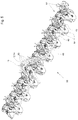
- Fig. 5 shows a seed drill 50 with a distribution device 10, to the outlet openings 14 of which eight lines 16 are connected.
- Each line 16 outgoing from the distribution device 10 opens in its course into a Y-switch 40, at which the lines 16 branch into two line strands.
- the branching into two lines is required, for example, in order to continuously supply the double disc coulters 54 of a double-row sowing unit 52 with solids in addition to the seeds during sowing.
- the double-row sowing units 52 it is possible, for example, to deposit single grains in a double rows that are advantageous in terms of plant cultivation, in particular in a zigzag formation.
- the distances between the double-row sowing units 52 are significantly greater than the distances between the associated double-disc coulters 54 within the double row, that is to say in a ratio of 3: 1 or greater. Dosing and depositing the individual grains is also more precise and safer due to the improved distribution in the distribution chamber 12.
Landscapes
- Life Sciences & Earth Sciences (AREA)
- Soil Sciences (AREA)
- Environmental Sciences (AREA)
- Sowing (AREA)
- Fertilizing (AREA)
- Filling Or Emptying Of Bunkers, Hoppers, And Tanks (AREA)
Priority Applications (1)
| Application Number | Priority Date | Filing Date | Title |
|---|---|---|---|
| PL19212693T PL3662732T3 (pl) | 2018-12-03 | 2019-11-29 | Maszyna rolnicza do wyprowadzania ziarnistych substancji stałych z pneumatycznym systemem transportowym |
Applications Claiming Priority (1)
| Application Number | Priority Date | Filing Date | Title |
|---|---|---|---|
| DE102018130638.5A DE102018130638A1 (de) | 2018-12-03 | 2018-12-03 | Landwirtschaftliche Maschine zur Ausbringung von körnigen Feststoffen mit einem pneumatischen Fördersystem |
Publications (2)
| Publication Number | Publication Date |
|---|---|
| EP3662732A1 EP3662732A1 (de) | 2020-06-10 |
| EP3662732B1 true EP3662732B1 (de) | 2021-11-10 |
Family
ID=68762474
Family Applications (1)
| Application Number | Title | Priority Date | Filing Date |
|---|---|---|---|
| EP19212693.6A Active EP3662732B1 (de) | 2018-12-03 | 2019-11-29 | Landwirtschaftliche maschine zur ausbringung von körnigen feststoffen mit einem pneumatischen fördersystem |
Country Status (5)
| Country | Link |
|---|---|
| EP (1) | EP3662732B1 (pl) |
| DE (1) | DE102018130638A1 (pl) |
| ES (1) | ES2904661T3 (pl) |
| HU (1) | HUE057010T2 (pl) |
| PL (1) | PL3662732T3 (pl) |
Families Citing this family (2)
| Publication number | Priority date | Publication date | Assignee | Title |
|---|---|---|---|---|
| CN112889419B (zh) * | 2021-03-11 | 2025-07-18 | 山东省农业机械科学研究院 | 一种多作物自适应输种与均匀布种装置 |
| DE102024107968A1 (de) * | 2023-09-21 | 2025-03-27 | Continental Engineering Services Gmbh | Saatgutvorrichtung |
Family Cites Families (8)
| Publication number | Priority date | Publication date | Assignee | Title |
|---|---|---|---|---|
| DD157290A1 (de) | 1981-03-18 | 1982-11-03 | Norbert Schaedel | Dosiervorrichtung von feststoff-luftstroemungen,insbesondere fuer drillmaschinen |
| DE3805148C1 (pl) * | 1988-02-19 | 1988-12-22 | Accord-Landmaschinen Heinrich Weiste & Co Gmbh, 4770 Soest, De | |
| NL8801011A (nl) * | 1988-04-19 | 1989-11-16 | Multinorm Bv | Inrichting voor het in de grond brengen van korrel- of poedervormige stoffen. |
| DE19542057C2 (de) | 1995-11-10 | 1999-06-10 | Lemken Gmbh & Co Kg | Pneumatische Sämaschine |
| CA2260439C (en) * | 1998-02-06 | 2007-10-02 | Robert Poncelet | Improved conveyor tube and distribution header for air conveyor |
| DE102009031066B4 (de) * | 2009-06-30 | 2015-10-01 | Lemken Gmbh & Co. Kg | Verteiler für pneumatische Drillmaschine |
| EP2932818B1 (de) * | 2014-04-16 | 2018-08-01 | Horsch Maschinen GmbH | Verteilvorrichtung und Verfahren zum Ausbringen von granulatartigem Verteilgut |
| DE102014108769A1 (de) * | 2014-06-24 | 2015-12-24 | Amazonen-Werke H. Dreyer Gmbh & Co. Kg | Pneumatische Sämaschine |
-
2018
- 2018-12-03 DE DE102018130638.5A patent/DE102018130638A1/de not_active Withdrawn
-
2019
- 2019-11-29 PL PL19212693T patent/PL3662732T3/pl unknown
- 2019-11-29 ES ES19212693T patent/ES2904661T3/es active Active
- 2019-11-29 HU HUE19212693A patent/HUE057010T2/hu unknown
- 2019-11-29 EP EP19212693.6A patent/EP3662732B1/de active Active
Also Published As
| Publication number | Publication date |
|---|---|
| HUE057010T2 (hu) | 2022-04-28 |
| PL3662732T3 (pl) | 2022-02-21 |
| DE102018130638A1 (de) | 2020-06-04 |
| ES2904661T3 (es) | 2022-04-05 |
| EP3662732A1 (de) | 2020-06-10 |
Similar Documents
| Publication | Publication Date | Title |
|---|---|---|
| EP3372065B1 (de) | Verteilerturm einer landwirtschaftlichen maschine, landwirtschaftliche maschine und verfahren zum betreiben einer solchen landwirtschaftlichen maschine | |
| EP3355673B1 (de) | Verteilturm einer landwirtschaftlichen verteilmaschine und verfahren zur reihenabschaltung an einem derartigen verteilturm | |
| EP3372064B1 (de) | Verteilerturm einer landwirtschaftlichen maschine, landwirtschaftliche maschine und verfahren zum betreiben einer solchen landwirtschaftlichen maschine | |
| EP2959762B1 (de) | Pneumatische sämaschine | |
| EP1994815B1 (de) | Verteilerkopf für eine Sä- oder Düngemaschine | |
| DE202020104231U1 (de) | Landwirtschaftliche pneumatische Verteilmaschine | |
| DE102017203854A1 (de) | Verteilerturm einer landwirtschaftlichen Maschine, landwirtschaftliche Maschine und Verfahren zum Betreiben einer solchen landwirtschaftlichen Maschine | |
| DE2101143B2 (de) | Vorrichtung zum kontinuierlichen thermischen Behandeln körnigen Gutes mittels eines Gases | |
| EP3662732B1 (de) | Landwirtschaftliche maschine zur ausbringung von körnigen feststoffen mit einem pneumatischen fördersystem | |
| EP3662731B1 (de) | Maschine zur ausbringung von körnigen feststoffen mit einem pneumatischen fördersystem | |
| DE602004002816T2 (de) | Verfahren zum Verteilen von Dünger oder anderem kornförmigen Material | |
| DE69927309T2 (de) | Verteilerleitung und Verteilerkopf für pneumatische Förderer | |
| DE2851797A1 (de) | Maschine zum ausstreuen von koernigem material | |
| EP2829167A1 (de) | Verteiler für eine pneumatische Verteilmaschine | |
| DE102008009211A1 (de) | Verteiler für eine pneumatische Verteilmaschine | |
| DE112014002036T5 (de) | Anlage zum Herstellen von Saugkörpern für Windeln | |
| DE102014014080A1 (de) | Landwirtschaftliche Verteilmaschine | |
| EP3352558B1 (de) | Verfahren und einrichtung zur lenkung einer körniges gut umfassenden strömung auf verschiedene leitungen, sowie hiermit ausgestattete vorrichtung zur verteilung körnigen guts auf eine veränderliche anzahl von leitungen | |
| DE102020109024A1 (de) | Landwirtschaftliche pneumatische Verteilmaschine | |
| DE102013108361A1 (de) | Vorrichtung, Anlage und Verfahren zur Trocknung von biologischem Schüttgut, insbesondere Hopfen | |
| EP2363015B1 (de) | Verteiler für eine pneumatische Verteilmaschine | |
| DE19735571C2 (de) | Spinneinrichtung zum Ausspinnen von Filamenten aus synthetischen Polymeren | |
| DE1532243B1 (de) | Verfahren und Vorrichtung zum Foerdern von Tabak | |
| DE4115353C2 (de) | Folienblasanlage zur Herstellung von Kunststoffolien | |
| DE202008008219U1 (de) | Verschlussvorrichtung für einen Verteilerkopf |
Legal Events
| Date | Code | Title | Description |
|---|---|---|---|
| PUAI | Public reference made under article 153(3) epc to a published international application that has entered the european phase |
Free format text: ORIGINAL CODE: 0009012 |
|
| STAA | Information on the status of an ep patent application or granted ep patent |
Free format text: STATUS: THE APPLICATION HAS BEEN PUBLISHED |
|
| AK | Designated contracting states |
Kind code of ref document: A1 Designated state(s): AL AT BE BG CH CY CZ DE DK EE ES FI FR GB GR HR HU IE IS IT LI LT LU LV MC MK MT NL NO PL PT RO RS SE SI SK SM TR |
|
| AX | Request for extension of the european patent |
Extension state: BA ME |
|
| STAA | Information on the status of an ep patent application or granted ep patent |
Free format text: STATUS: REQUEST FOR EXAMINATION WAS MADE |
|
| 17P | Request for examination filed |
Effective date: 20201210 |
|
| RBV | Designated contracting states (corrected) |
Designated state(s): AL AT BE BG CH CY CZ DE DK EE ES FI FR GB GR HR HU IE IS IT LI LT LU LV MC MK MT NL NO PL PT RO RS SE SI SK SM TR |
|
| GRAP | Despatch of communication of intention to grant a patent |
Free format text: ORIGINAL CODE: EPIDOSNIGR1 |
|
| STAA | Information on the status of an ep patent application or granted ep patent |
Free format text: STATUS: GRANT OF PATENT IS INTENDED |
|
| RIC1 | Information provided on ipc code assigned before grant |
Ipc: A01C 7/08 20060101AFI20210520BHEP Ipc: A01C 7/10 20060101ALN20210520BHEP |
|
| INTG | Intention to grant announced |
Effective date: 20210607 |
|
| RIC1 | Information provided on ipc code assigned before grant |
Ipc: A01C 7/08 20060101AFI20210525BHEP Ipc: A01C 7/10 20060101ALN20210525BHEP |
|
| GRAS | Grant fee paid |
Free format text: ORIGINAL CODE: EPIDOSNIGR3 |
|
| GRAA | (expected) grant |
Free format text: ORIGINAL CODE: 0009210 |
|
| STAA | Information on the status of an ep patent application or granted ep patent |
Free format text: STATUS: THE PATENT HAS BEEN GRANTED |
|
| AK | Designated contracting states |
Kind code of ref document: B1 Designated state(s): AL AT BE BG CH CY CZ DE DK EE ES FI FR GB GR HR HU IE IS IT LI LT LU LV MC MK MT NL NO PL PT RO RS SE SI SK SM TR |
|
| REG | Reference to a national code |
Ref country code: GB Ref legal event code: FG4D Free format text: NOT ENGLISH |
|
| REG | Reference to a national code |
Ref country code: AT Ref legal event code: REF Ref document number: 1445184 Country of ref document: AT Kind code of ref document: T Effective date: 20211115 Ref country code: CH Ref legal event code: EP |
|
| REG | Reference to a national code |
Ref country code: DE Ref legal event code: R096 Ref document number: 502019002717 Country of ref document: DE |
|
| REG | Reference to a national code |
Ref country code: IE Ref legal event code: FG4D Free format text: LANGUAGE OF EP DOCUMENT: GERMAN |
|
| REG | Reference to a national code |
Ref country code: SE Ref legal event code: TRGR |
|
| REG | Reference to a national code |
Ref country code: NL Ref legal event code: FP |
|
| REG | Reference to a national code |
Ref country code: LT Ref legal event code: MG9D |
|
| REG | Reference to a national code |
Ref country code: ES Ref legal event code: FG2A Ref document number: 2904661 Country of ref document: ES Kind code of ref document: T3 Effective date: 20220405 |
|
| REG | Reference to a national code |
Ref country code: HU Ref legal event code: AG4A Ref document number: E057010 Country of ref document: HU |
|
| PG25 | Lapsed in a contracting state [announced via postgrant information from national office to epo] |
Ref country code: RS Free format text: LAPSE BECAUSE OF FAILURE TO SUBMIT A TRANSLATION OF THE DESCRIPTION OR TO PAY THE FEE WITHIN THE PRESCRIBED TIME-LIMIT Effective date: 20211110 Ref country code: LT Free format text: LAPSE BECAUSE OF FAILURE TO SUBMIT A TRANSLATION OF THE DESCRIPTION OR TO PAY THE FEE WITHIN THE PRESCRIBED TIME-LIMIT Effective date: 20211110 Ref country code: FI Free format text: LAPSE BECAUSE OF FAILURE TO SUBMIT A TRANSLATION OF THE DESCRIPTION OR TO PAY THE FEE WITHIN THE PRESCRIBED TIME-LIMIT Effective date: 20211110 Ref country code: BG Free format text: LAPSE BECAUSE OF FAILURE TO SUBMIT A TRANSLATION OF THE DESCRIPTION OR TO PAY THE FEE WITHIN THE PRESCRIBED TIME-LIMIT Effective date: 20220210 |
|
| PG25 | Lapsed in a contracting state [announced via postgrant information from national office to epo] |
Ref country code: IS Free format text: LAPSE BECAUSE OF FAILURE TO SUBMIT A TRANSLATION OF THE DESCRIPTION OR TO PAY THE FEE WITHIN THE PRESCRIBED TIME-LIMIT Effective date: 20220310 Ref country code: PT Free format text: LAPSE BECAUSE OF FAILURE TO SUBMIT A TRANSLATION OF THE DESCRIPTION OR TO PAY THE FEE WITHIN THE PRESCRIBED TIME-LIMIT Effective date: 20220310 Ref country code: NO Free format text: LAPSE BECAUSE OF FAILURE TO SUBMIT A TRANSLATION OF THE DESCRIPTION OR TO PAY THE FEE WITHIN THE PRESCRIBED TIME-LIMIT Effective date: 20220210 Ref country code: LV Free format text: LAPSE BECAUSE OF FAILURE TO SUBMIT A TRANSLATION OF THE DESCRIPTION OR TO PAY THE FEE WITHIN THE PRESCRIBED TIME-LIMIT Effective date: 20211110 Ref country code: HR Free format text: LAPSE BECAUSE OF FAILURE TO SUBMIT A TRANSLATION OF THE DESCRIPTION OR TO PAY THE FEE WITHIN THE PRESCRIBED TIME-LIMIT Effective date: 20211110 Ref country code: GR Free format text: LAPSE BECAUSE OF FAILURE TO SUBMIT A TRANSLATION OF THE DESCRIPTION OR TO PAY THE FEE WITHIN THE PRESCRIBED TIME-LIMIT Effective date: 20220211 |
|
| PG25 | Lapsed in a contracting state [announced via postgrant information from national office to epo] |
Ref country code: SM Free format text: LAPSE BECAUSE OF FAILURE TO SUBMIT A TRANSLATION OF THE DESCRIPTION OR TO PAY THE FEE WITHIN THE PRESCRIBED TIME-LIMIT Effective date: 20211110 Ref country code: SK Free format text: LAPSE BECAUSE OF FAILURE TO SUBMIT A TRANSLATION OF THE DESCRIPTION OR TO PAY THE FEE WITHIN THE PRESCRIBED TIME-LIMIT Effective date: 20211110 Ref country code: RO Free format text: LAPSE BECAUSE OF FAILURE TO SUBMIT A TRANSLATION OF THE DESCRIPTION OR TO PAY THE FEE WITHIN THE PRESCRIBED TIME-LIMIT Effective date: 20211110 Ref country code: LU Free format text: LAPSE BECAUSE OF NON-PAYMENT OF DUE FEES Effective date: 20211129 Ref country code: EE Free format text: LAPSE BECAUSE OF FAILURE TO SUBMIT A TRANSLATION OF THE DESCRIPTION OR TO PAY THE FEE WITHIN THE PRESCRIBED TIME-LIMIT Effective date: 20211110 Ref country code: DK Free format text: LAPSE BECAUSE OF FAILURE TO SUBMIT A TRANSLATION OF THE DESCRIPTION OR TO PAY THE FEE WITHIN THE PRESCRIBED TIME-LIMIT Effective date: 20211110 |
|
| REG | Reference to a national code |
Ref country code: DE Ref legal event code: R097 Ref document number: 502019002717 Country of ref document: DE |
|
| PG25 | Lapsed in a contracting state [announced via postgrant information from national office to epo] |
Ref country code: MC Free format text: LAPSE BECAUSE OF FAILURE TO SUBMIT A TRANSLATION OF THE DESCRIPTION OR TO PAY THE FEE WITHIN THE PRESCRIBED TIME-LIMIT Effective date: 20211110 |
|
| PLBE | No opposition filed within time limit |
Free format text: ORIGINAL CODE: 0009261 |
|
| STAA | Information on the status of an ep patent application or granted ep patent |
Free format text: STATUS: NO OPPOSITION FILED WITHIN TIME LIMIT |
|
| 26N | No opposition filed |
Effective date: 20220811 |
|
| PG25 | Lapsed in a contracting state [announced via postgrant information from national office to epo] |
Ref country code: IE Free format text: LAPSE BECAUSE OF NON-PAYMENT OF DUE FEES Effective date: 20211129 Ref country code: AL Free format text: LAPSE BECAUSE OF FAILURE TO SUBMIT A TRANSLATION OF THE DESCRIPTION OR TO PAY THE FEE WITHIN THE PRESCRIBED TIME-LIMIT Effective date: 20211110 |
|
| PG25 | Lapsed in a contracting state [announced via postgrant information from national office to epo] |
Ref country code: SI Free format text: LAPSE BECAUSE OF FAILURE TO SUBMIT A TRANSLATION OF THE DESCRIPTION OR TO PAY THE FEE WITHIN THE PRESCRIBED TIME-LIMIT Effective date: 20211110 |
|
| P01 | Opt-out of the competence of the unified patent court (upc) registered |
Effective date: 20230518 |
|
| PG25 | Lapsed in a contracting state [announced via postgrant information from national office to epo] |
Ref country code: CY Free format text: LAPSE BECAUSE OF FAILURE TO SUBMIT A TRANSLATION OF THE DESCRIPTION OR TO PAY THE FEE WITHIN THE PRESCRIBED TIME-LIMIT Effective date: 20211110 |
|
| REG | Reference to a national code |
Ref country code: CH Ref legal event code: PL |
|
| PG25 | Lapsed in a contracting state [announced via postgrant information from national office to epo] |
Ref country code: LI Free format text: LAPSE BECAUSE OF NON-PAYMENT OF DUE FEES Effective date: 20221130 Ref country code: CH Free format text: LAPSE BECAUSE OF NON-PAYMENT OF DUE FEES Effective date: 20221130 |
|
| PGFP | Annual fee paid to national office [announced via postgrant information from national office to epo] |
Ref country code: NL Payment date: 20231124 Year of fee payment: 5 |
|
| PGFP | Annual fee paid to national office [announced via postgrant information from national office to epo] |
Ref country code: ES Payment date: 20231219 Year of fee payment: 5 |
|
| PGFP | Annual fee paid to national office [announced via postgrant information from national office to epo] |
Ref country code: HU Payment date: 20231121 Year of fee payment: 5 |
|
| PG25 | Lapsed in a contracting state [announced via postgrant information from national office to epo] |
Ref country code: MK Free format text: LAPSE BECAUSE OF FAILURE TO SUBMIT A TRANSLATION OF THE DESCRIPTION OR TO PAY THE FEE WITHIN THE PRESCRIBED TIME-LIMIT Effective date: 20211110 |
|
| PG25 | Lapsed in a contracting state [announced via postgrant information from national office to epo] |
Ref country code: MT Free format text: LAPSE BECAUSE OF FAILURE TO SUBMIT A TRANSLATION OF THE DESCRIPTION OR TO PAY THE FEE WITHIN THE PRESCRIBED TIME-LIMIT Effective date: 20211110 |
|
| PGFP | Annual fee paid to national office [announced via postgrant information from national office to epo] |
Ref country code: DE Payment date: 20241106 Year of fee payment: 6 |
|
| PGFP | Annual fee paid to national office [announced via postgrant information from national office to epo] |
Ref country code: BE Payment date: 20241126 Year of fee payment: 6 Ref country code: PL Payment date: 20241115 Year of fee payment: 6 |
|
| PGFP | Annual fee paid to national office [announced via postgrant information from national office to epo] |
Ref country code: GB Payment date: 20241126 Year of fee payment: 6 |
|
| PGFP | Annual fee paid to national office [announced via postgrant information from national office to epo] |
Ref country code: FR Payment date: 20241126 Year of fee payment: 6 |
|
| PGFP | Annual fee paid to national office [announced via postgrant information from national office to epo] |
Ref country code: AT Payment date: 20241119 Year of fee payment: 6 |
|
| PGFP | Annual fee paid to national office [announced via postgrant information from national office to epo] |
Ref country code: CZ Payment date: 20241121 Year of fee payment: 6 |
|
| PGFP | Annual fee paid to national office [announced via postgrant information from national office to epo] |
Ref country code: IT Payment date: 20241125 Year of fee payment: 6 |
|
| PGFP | Annual fee paid to national office [announced via postgrant information from national office to epo] |
Ref country code: SE Payment date: 20241126 Year of fee payment: 6 |
|
| REG | Reference to a national code |
Ref country code: NL Ref legal event code: MM Effective date: 20241201 |
|
| PG25 | Lapsed in a contracting state [announced via postgrant information from national office to epo] |
Ref country code: HU Free format text: LAPSE BECAUSE OF NON-PAYMENT OF DUE FEES Effective date: 20241130 |
|
| PG25 | Lapsed in a contracting state [announced via postgrant information from national office to epo] |
Ref country code: NL Free format text: LAPSE BECAUSE OF NON-PAYMENT OF DUE FEES Effective date: 20241201 |
|
| PG25 | Lapsed in a contracting state [announced via postgrant information from national office to epo] |
Ref country code: TR Free format text: LAPSE BECAUSE OF FAILURE TO SUBMIT A TRANSLATION OF THE DESCRIPTION OR TO PAY THE FEE WITHIN THE PRESCRIBED TIME-LIMIT Effective date: 20211110 |