EP3660912A1 - Anzeigevorrichtung - Google Patents
Anzeigevorrichtung Download PDFInfo
- Publication number
- EP3660912A1 EP3660912A1 EP19209886.1A EP19209886A EP3660912A1 EP 3660912 A1 EP3660912 A1 EP 3660912A1 EP 19209886 A EP19209886 A EP 19209886A EP 3660912 A1 EP3660912 A1 EP 3660912A1
- Authority
- EP
- European Patent Office
- Prior art keywords
- region
- line
- parts
- disposed
- module
- Prior art date
- Legal status (The legal status is an assumption and is not a legal conclusion. Google has not performed a legal analysis and makes no representation as to the accuracy of the status listed.)
- Pending
Links
- 238000002834 transmittance Methods 0.000 claims description 7
- 239000010410 layer Substances 0.000 description 167
- 230000002093 peripheral effect Effects 0.000 description 27
- 101000658110 Homo sapiens Synaptotagmin-like protein 2 Proteins 0.000 description 16
- 102100035007 Synaptotagmin-like protein 2 Human genes 0.000 description 16
- 239000012044 organic layer Substances 0.000 description 15
- 101000820585 Homo sapiens SUN domain-containing ossification factor Proteins 0.000 description 12
- 101000673946 Homo sapiens Synaptotagmin-like protein 1 Proteins 0.000 description 12
- 102100040541 Synaptotagmin-like protein 1 Human genes 0.000 description 12
- 239000000463 material Substances 0.000 description 12
- 230000015654 memory Effects 0.000 description 11
- 238000000034 method Methods 0.000 description 11
- 102100024538 Cdc42 effector protein 1 Human genes 0.000 description 10
- 102100024492 Cdc42 effector protein 2 Human genes 0.000 description 10
- 101000762448 Homo sapiens Cdc42 effector protein 1 Proteins 0.000 description 10
- 101000762417 Homo sapiens Cdc42 effector protein 2 Proteins 0.000 description 10
- 101000941711 Homo sapiens Centriolin Proteins 0.000 description 10
- 101000745836 Homo sapiens Centrosome-associated protein CEP250 Proteins 0.000 description 10
- 239000000758 substrate Substances 0.000 description 10
- 239000003990 capacitor Substances 0.000 description 9
- 239000013256 coordination polymer Substances 0.000 description 8
- 230000008569 process Effects 0.000 description 8
- 238000005538 encapsulation Methods 0.000 description 7
- 239000004065 semiconductor Substances 0.000 description 7
- 230000004888 barrier function Effects 0.000 description 6
- 238000004891 communication Methods 0.000 description 6
- 230000006870 function Effects 0.000 description 6
- 238000004519 manufacturing process Methods 0.000 description 6
- 239000002184 metal Substances 0.000 description 6
- 229910052751 metal Inorganic materials 0.000 description 6
- 238000000151 deposition Methods 0.000 description 5
- 230000008021 deposition Effects 0.000 description 5
- 230000003287 optical effect Effects 0.000 description 5
- 239000002356 single layer Substances 0.000 description 5
- 239000000853 adhesive Substances 0.000 description 4
- 230000001070 adhesive effect Effects 0.000 description 4
- 238000003491 array Methods 0.000 description 4
- QVGXLLKOCUKJST-UHFFFAOYSA-N atomic oxygen Chemical compound [O] QVGXLLKOCUKJST-UHFFFAOYSA-N 0.000 description 4
- 230000005540 biological transmission Effects 0.000 description 4
- 238000010586 diagram Methods 0.000 description 4
- 239000011521 glass Substances 0.000 description 4
- 229910010272 inorganic material Inorganic materials 0.000 description 4
- 239000011147 inorganic material Substances 0.000 description 4
- 239000001301 oxygen Substances 0.000 description 4
- 229910052760 oxygen Inorganic materials 0.000 description 4
- 230000004044 response Effects 0.000 description 4
- 238000007789 sealing Methods 0.000 description 4
- 230000035945 sensitivity Effects 0.000 description 4
- 230000005236 sound signal Effects 0.000 description 4
- 239000011368 organic material Substances 0.000 description 3
- 239000004033 plastic Substances 0.000 description 3
- 229910052581 Si3N4 Inorganic materials 0.000 description 2
- VYPSYNLAJGMNEJ-UHFFFAOYSA-N Silicium dioxide Chemical compound O=[Si]=O VYPSYNLAJGMNEJ-UHFFFAOYSA-N 0.000 description 2
- XUIMIQQOPSSXEZ-UHFFFAOYSA-N Silicon Chemical compound [Si] XUIMIQQOPSSXEZ-UHFFFAOYSA-N 0.000 description 2
- 150000001875 compounds Chemical class 0.000 description 2
- 239000004020 conductor Substances 0.000 description 2
- 238000005137 deposition process Methods 0.000 description 2
- 238000013461 design Methods 0.000 description 2
- 230000000149 penetrating effect Effects 0.000 description 2
- 230000035515 penetration Effects 0.000 description 2
- 239000002985 plastic film Substances 0.000 description 2
- 229920006255 plastic film Polymers 0.000 description 2
- 238000012545 processing Methods 0.000 description 2
- 229920005989 resin Polymers 0.000 description 2
- 239000011347 resin Substances 0.000 description 2
- 229910052710 silicon Inorganic materials 0.000 description 2
- 239000010703 silicon Substances 0.000 description 2
- HQVNEWCFYHHQES-UHFFFAOYSA-N silicon nitride Chemical compound N12[Si]34N5[Si]62N3[Si]51N64 HQVNEWCFYHHQES-UHFFFAOYSA-N 0.000 description 2
- 229910052814 silicon oxide Inorganic materials 0.000 description 2
- 239000004925 Acrylic resin Substances 0.000 description 1
- 229920000178 Acrylic resin Polymers 0.000 description 1
- RYGMFSIKBFXOCR-UHFFFAOYSA-N Copper Chemical compound [Cu] RYGMFSIKBFXOCR-UHFFFAOYSA-N 0.000 description 1
- 239000004593 Epoxy Substances 0.000 description 1
- 230000015572 biosynthetic process Effects 0.000 description 1
- 230000000903 blocking effect Effects 0.000 description 1
- 230000008859 change Effects 0.000 description 1
- 239000011248 coating agent Substances 0.000 description 1
- 238000000576 coating method Methods 0.000 description 1
- 238000010924 continuous production Methods 0.000 description 1
- 230000007547 defect Effects 0.000 description 1
- 238000005516 engineering process Methods 0.000 description 1
- 239000000835 fiber Substances 0.000 description 1
- 239000012530 fluid Substances 0.000 description 1
- 239000007789 gas Substances 0.000 description 1
- 239000011810 insulating material Substances 0.000 description 1
- 238000010030 laminating Methods 0.000 description 1
- 239000002245 particle Substances 0.000 description 1
- 229920000642 polymer Polymers 0.000 description 1
- 239000002096 quantum dot Substances 0.000 description 1
- 230000035939 shock Effects 0.000 description 1
- 238000004528 spin coating Methods 0.000 description 1
- 230000003068 static effect Effects 0.000 description 1
- 238000012360 testing method Methods 0.000 description 1
- 229920005992 thermoplastic resin Polymers 0.000 description 1
Images


Classifications
-
- H—ELECTRICITY
- H10—SEMICONDUCTOR DEVICES; ELECTRIC SOLID-STATE DEVICES NOT OTHERWISE PROVIDED FOR
- H10K—ORGANIC ELECTRIC SOLID-STATE DEVICES
- H10K59/00—Integrated devices, or assemblies of multiple devices, comprising at least one organic light-emitting element covered by group H10K50/00
- H10K59/10—OLED displays
- H10K59/17—Passive-matrix OLED displays
- H10K59/179—Interconnections, e.g. wiring lines or terminals
-
- G—PHYSICS
- G09—EDUCATION; CRYPTOGRAPHY; DISPLAY; ADVERTISING; SEALS
- G09G—ARRANGEMENTS OR CIRCUITS FOR CONTROL OF INDICATING DEVICES USING STATIC MEANS TO PRESENT VARIABLE INFORMATION
- G09G3/00—Control arrangements or circuits, of interest only in connection with visual indicators other than cathode-ray tubes
- G09G3/20—Control arrangements or circuits, of interest only in connection with visual indicators other than cathode-ray tubes for presentation of an assembly of a number of characters, e.g. a page, by composing the assembly by combination of individual elements arranged in a matrix no fixed position being assigned to or needed to be assigned to the individual characters or partial characters
- G09G3/22—Control arrangements or circuits, of interest only in connection with visual indicators other than cathode-ray tubes for presentation of an assembly of a number of characters, e.g. a page, by composing the assembly by combination of individual elements arranged in a matrix no fixed position being assigned to or needed to be assigned to the individual characters or partial characters using controlled light sources
- G09G3/30—Control arrangements or circuits, of interest only in connection with visual indicators other than cathode-ray tubes for presentation of an assembly of a number of characters, e.g. a page, by composing the assembly by combination of individual elements arranged in a matrix no fixed position being assigned to or needed to be assigned to the individual characters or partial characters using controlled light sources using electroluminescent panels
- G09G3/32—Control arrangements or circuits, of interest only in connection with visual indicators other than cathode-ray tubes for presentation of an assembly of a number of characters, e.g. a page, by composing the assembly by combination of individual elements arranged in a matrix no fixed position being assigned to or needed to be assigned to the individual characters or partial characters using controlled light sources using electroluminescent panels semiconductive, e.g. using light-emitting diodes [LED]
- G09G3/3208—Control arrangements or circuits, of interest only in connection with visual indicators other than cathode-ray tubes for presentation of an assembly of a number of characters, e.g. a page, by composing the assembly by combination of individual elements arranged in a matrix no fixed position being assigned to or needed to be assigned to the individual characters or partial characters using controlled light sources using electroluminescent panels semiconductive, e.g. using light-emitting diodes [LED] organic, e.g. using organic light-emitting diodes [OLED]
- G09G3/3225—Control arrangements or circuits, of interest only in connection with visual indicators other than cathode-ray tubes for presentation of an assembly of a number of characters, e.g. a page, by composing the assembly by combination of individual elements arranged in a matrix no fixed position being assigned to or needed to be assigned to the individual characters or partial characters using controlled light sources using electroluminescent panels semiconductive, e.g. using light-emitting diodes [LED] organic, e.g. using organic light-emitting diodes [OLED] using an active matrix
- G09G3/3233—Control arrangements or circuits, of interest only in connection with visual indicators other than cathode-ray tubes for presentation of an assembly of a number of characters, e.g. a page, by composing the assembly by combination of individual elements arranged in a matrix no fixed position being assigned to or needed to be assigned to the individual characters or partial characters using controlled light sources using electroluminescent panels semiconductive, e.g. using light-emitting diodes [LED] organic, e.g. using organic light-emitting diodes [OLED] using an active matrix with pixel circuitry controlling the current through the light-emitting element
-
- G—PHYSICS
- G09—EDUCATION; CRYPTOGRAPHY; DISPLAY; ADVERTISING; SEALS
- G09F—DISPLAYING; ADVERTISING; SIGNS; LABELS OR NAME-PLATES; SEALS
- G09F9/00—Indicating arrangements for variable information in which the information is built-up on a support by selection or combination of individual elements
- G09F9/30—Indicating arrangements for variable information in which the information is built-up on a support by selection or combination of individual elements in which the desired character or characters are formed by combining individual elements
-
- H—ELECTRICITY
- H10—SEMICONDUCTOR DEVICES; ELECTRIC SOLID-STATE DEVICES NOT OTHERWISE PROVIDED FOR
- H10K—ORGANIC ELECTRIC SOLID-STATE DEVICES
- H10K59/00—Integrated devices, or assemblies of multiple devices, comprising at least one organic light-emitting element covered by group H10K50/00
- H10K59/10—OLED displays
- H10K59/12—Active-matrix OLED [AMOLED] displays
- H10K59/131—Interconnections, e.g. wiring lines or terminals
-
- G—PHYSICS
- G09—EDUCATION; CRYPTOGRAPHY; DISPLAY; ADVERTISING; SEALS
- G09G—ARRANGEMENTS OR CIRCUITS FOR CONTROL OF INDICATING DEVICES USING STATIC MEANS TO PRESENT VARIABLE INFORMATION
- G09G3/00—Control arrangements or circuits, of interest only in connection with visual indicators other than cathode-ray tubes
- G09G3/20—Control arrangements or circuits, of interest only in connection with visual indicators other than cathode-ray tubes for presentation of an assembly of a number of characters, e.g. a page, by composing the assembly by combination of individual elements arranged in a matrix no fixed position being assigned to or needed to be assigned to the individual characters or partial characters
-
- H—ELECTRICITY
- H10—SEMICONDUCTOR DEVICES; ELECTRIC SOLID-STATE DEVICES NOT OTHERWISE PROVIDED FOR
- H10K—ORGANIC ELECTRIC SOLID-STATE DEVICES
- H10K59/00—Integrated devices, or assemblies of multiple devices, comprising at least one organic light-emitting element covered by group H10K50/00
- H10K59/10—OLED displays
- H10K59/12—Active-matrix OLED [AMOLED] displays
- H10K59/123—Connection of the pixel electrodes to the thin film transistors [TFT]
-
- H—ELECTRICITY
- H10—SEMICONDUCTOR DEVICES; ELECTRIC SOLID-STATE DEVICES NOT OTHERWISE PROVIDED FOR
- H10K—ORGANIC ELECTRIC SOLID-STATE DEVICES
- H10K59/00—Integrated devices, or assemblies of multiple devices, comprising at least one organic light-emitting element covered by group H10K50/00
- H10K59/10—OLED displays
- H10K59/12—Active-matrix OLED [AMOLED] displays
- H10K59/124—Insulating layers formed between TFT elements and OLED elements
-
- G—PHYSICS
- G09—EDUCATION; CRYPTOGRAPHY; DISPLAY; ADVERTISING; SEALS
- G09G—ARRANGEMENTS OR CIRCUITS FOR CONTROL OF INDICATING DEVICES USING STATIC MEANS TO PRESENT VARIABLE INFORMATION
- G09G2300/00—Aspects of the constitution of display devices
- G09G2300/04—Structural and physical details of display devices
- G09G2300/0421—Structural details of the set of electrodes
- G09G2300/0426—Layout of electrodes and connections
-
- G—PHYSICS
- G09—EDUCATION; CRYPTOGRAPHY; DISPLAY; ADVERTISING; SEALS
- G09G—ARRANGEMENTS OR CIRCUITS FOR CONTROL OF INDICATING DEVICES USING STATIC MEANS TO PRESENT VARIABLE INFORMATION
- G09G2310/00—Command of the display device
- G09G2310/02—Addressing, scanning or driving the display screen or processing steps related thereto
- G09G2310/0202—Addressing of scan or signal lines
-
- H—ELECTRICITY
- H10—SEMICONDUCTOR DEVICES; ELECTRIC SOLID-STATE DEVICES NOT OTHERWISE PROVIDED FOR
- H10K—ORGANIC ELECTRIC SOLID-STATE DEVICES
- H10K59/00—Integrated devices, or assemblies of multiple devices, comprising at least one organic light-emitting element covered by group H10K50/00
- H10K59/60—OLEDs integrated with inorganic light-sensitive elements, e.g. with inorganic solar cells or inorganic photodiodes
- H10K59/65—OLEDs integrated with inorganic image sensors
-
- H—ELECTRICITY
- H10—SEMICONDUCTOR DEVICES; ELECTRIC SOLID-STATE DEVICES NOT OTHERWISE PROVIDED FOR
- H10K—ORGANIC ELECTRIC SOLID-STATE DEVICES
- H10K59/00—Integrated devices, or assemblies of multiple devices, comprising at least one organic light-emitting element covered by group H10K50/00
- H10K59/80—Constructional details
- H10K59/87—Passivation; Containers; Encapsulations
- H10K59/873—Encapsulations
- H10K59/8731—Encapsulations multilayered coatings having a repetitive structure, e.g. having multiple organic-inorganic bilayers
-
- H—ELECTRICITY
- H10—SEMICONDUCTOR DEVICES; ELECTRIC SOLID-STATE DEVICES NOT OTHERWISE PROVIDED FOR
- H10K—ORGANIC ELECTRIC SOLID-STATE DEVICES
- H10K59/00—Integrated devices, or assemblies of multiple devices, comprising at least one organic light-emitting element covered by group H10K50/00
- H10K59/80—Constructional details
- H10K59/88—Dummy elements, i.e. elements having non-functional features
Definitions
- Exemplary implementations of the invention relate generally to a display device, and more particularly, to a display device having improved display quality and provided with an electronic module having improved sensitivity.
- the first line and the second line may be disposed on layers different from each other, and the first connection part may be disposed on the same layer as one of the first line and the second line.
- the overlapped connection part may include a plurality of overlapped connection parts, one portion of each of two most adjacent overlapped connection parts to each other among the plurality of overlapped connection parts may not overlap each other when viewed in the first direction, and a remaining portion of the two most adjacent overlapped connection parts to each other may overlap each other in the first direction.
- Each of the second signal line parts may include: a third line; a fourth line spaced apart from the third line; and a second connection part configured to connect the third line and the fourth line, and at least a portion of the second connection parts of the second signal line parts may overlap at least a portion of the first signal line parts.
- the base layer, the first signal line parts, the second signal line parts, and the pixels constitute a display module; a first module region overlapping the first region, a second module region overlapping the second region, and a third module region overlapping the third region may be defined in the display module; and a transmittance of the first module region may be higher than that of the third module region.
- exemplary embodiments are described herein with reference to sectional and/or exploded illustrations that are schematic illustrations of idealized exemplary embodiments and/or intermediate structures. As such, variations from the shapes of the illustrations as a result, for example, of manufacturing techniques and/or tolerances, are to be expected. Thus, exemplary embodiments disclosed herein should not necessarily be construed as limited to the particular illustrated shapes of regions, but are to include deviations in shapes that result from, for instance, manufacturing. In this manner, regions illustrated in the drawings may be schematic in nature and the shapes of these regions may not reflect actual shapes of regions of a device and, as such, are not necessarily intended to be limiting.
- each block, unit, and/or module may be implemented by dedicated hardware, or as a combination of dedicated hardware to perform some functions and a processor (e.g., one or more programmed microprocessors and associated circuitry) to perform other functions.
- a processor e.g., one or more programmed microprocessors and associated circuitry
- each block, unit, and/or module of some exemplary embodiments may be physically separated into two or more interacting and discrete blocks, units, and/or modules without departing from the scope of the inventive concepts.
- the blocks, units, and/or modules of some exemplary embodiments may be physically combined into more complex blocks, units, and/or modules without departing from the scope of the inventive concepts.
- front surface (or upper surface) and rear surface (or lower surface) of each member is defined with respect to the direction in which the image IM is displayed.
- the front surface and the rear surface may be opposite to each other in the third direction DR3, and the normal direction of each of the front surface and the rear surface may be parallel to the third direction DR3.
- the directions indicated by the first to third directions DR1, DR2, and DR3 are relative and may be converted into other directions.
- the first to third directions are directions, which the first to third direction DR1, DR2, and DR3 respectively indicate, and referred to by the same reference symbols.
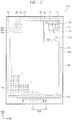
- the window 100 may be divided into a transmissive region TA and a bezel region BA when viewed in a plan view.
- the wording "on a plane” may mean a case of viewing in the third direction DR3.
- the "thickness direction” may be the third direction DR3.
- a sensing region SA may be a region overlapping the electronic module 500 to be described later.
- the display device EA may receive an external signal required for the electronic module 500 through the sensing region SA or provide a signal output from the electronic module 500 to the outside.
- the sensing region SA may be defined to overlap the transmissive region TA. Accordingly, a separate region, which is provided to provide the sensing region SA in a region other than the transmissive region TA, may be omitted. Thus, the area of the bezel region BZA may be reduced.
- FIG. 1B exemplarily illustrates that the number of sensing regions SA is one, but the exemplary embodiments are not limited thereto. For example, two or more sensing regions SA may be defined.
- FIG. 1B exemplarily illustrates that the sensing region SA is defined on an upper left end of the transmissive region TA, but the sensing region SA may be defined on various regions, such as, on the upper right end of the transmissive region TA, on the central portion of the transmissive region TA, on the lower left end of the transmissive region TA, or the lower right end of the transmissive region TA.
- the peripheral region NAA may be a region covered by the bezel region BZA.
- the peripheral region NAA is adjacent to the active region AA.
- the peripheral region NAA may surround the active region AA.
- a drive circuit, drive wiring, or the like which are for driving the active region AA may be disposed.
- the display panel 210 may be a component which actually generates an image IM.
- the image IM generated by the display panel 210 is displayed on the display surface IS, and is viewed by a user from the outside through the transmissive region TA.
- user's input may be provided in various forms, and the display device EA may also detect user's external input TC applied to a side surface or the rear surface of the display device EA according to the structure of the display device EA, and the exemplary embodiments are not limited to any one embodiment.
- the main circuit board MB may include various drive circuits for driving the display module 200, a connector for power supply, etc.
- the first flexible film CF1 and the second flexible film CF2 may be connected to the main circuit board MB.
- the display module 200 may easily be controlled through the one main circuit board MB.
- the display panel 210 and the input sensing unit 220 may also be connected to the main circuit boards different from each other, and either the first flexible film CF1 or the second flexible film CF2 may not be connected to the main circuit board MB, and the exemplary embodiments are not limited any one embodiment.
- one region corresponding to the sensing region SA in the display module 200 may have a relatively higher transmittance than the active region AA which does not overlap the sensing region SA.
- the electronic module 500 which is disposed to overlap the sensing region SA may easily transmit and/or receive a signal through the sensing region SA.
- the electronic module 500 may overlap the module hole MH and the sensing region SA.
- the electronic module 500 may be disposed under the display module 200 and at least a portion of the electronic module 500 may also be accommodated inside the module hole MH.
- the electronic module 500 may receive an external input transmitted through the sensing region SA or provide an output through the sensing region SA.
- the first electronic module EM1 may include a control module CM, a wireless communication module TM, an image input module IM, an audio input module AIM, a memory MM, and an external interface IF. Some of the modules may not be mounted on the mother board, but may also be electrically connected to the mother board through a flexible circuit board.
- the control module CM controls the overall operations of the display device EA.
- the control module CM may be a microprocessor.
- the control module CM may activate or deactivate the display module 200.
- the control module CM may control other modules such as the image input module IM or the audio input module AIM on the basis of a touch signal received from the display module 200.
- the groove parts GV1, GV2, and GV3 may be defined to be spaced apart from each other.
- the groove parts GV1, GV2, and GV3 are exemplarily illustrated as the first to third groove parts GV1, GV2, and GV3 which are formed to be spaced apart from a second region AR2 and sequentially formed in the direction approaching the module hole MH.
- Each of the first to third groove parts GV1, GV2, and GV3 may have a closed-line shape surrounding the module hole MH, and may also have an intermittent-line shape surrounding at least a portion of the periphery of the module hole MH, and the exemplary embodiments are not limited to any one embodiment.
- the first signal line parts SLP1 may be arrayed in the first direction DR1 so as to be spaced apart from each other, and the second signal line parts SLP2 may be arrayed in the second direction DR2 so as to be spaced apart from each other.
- the first connection part CEPlb may be disposed on the same layer as the first line LN1b, and may extend from the first line LN1b. In another exemplary embodiment, the first connection part CEPlb may be disposed on the same layer as the second line LN2b, and may extend from the second line LN2b.
- the first signal line part SLPlb may further include a dummy pattern D-LN2b.
- the dummy pattern D-LN2b may be disposed on the same layer as the second line LN2b.
- the dummy pattern D-LN2b may be electrically connected to the first connection part CEP1b.
- the dummy pattern D-LN2b may be omitted or also be connected to the second line LN2b.
- FIG. 15 is a view of a captured image of a region corresponding to the region YY' shown in FIG. 8 .
- FIG. 16 is a schematic plan view illustrating a region corresponding to region LL' of FIG. 15 .
- each of the overlapped connection part CEP-O and the non-overlapped connection part CEP-NO may be provided in plurality.
- the non-overlapped connection parts CEP-NO may be arrayed while being spaced apart from each other in the first direction DR1.
- the overlapped connection parts CEP-O may be arrayed zigzag with respect to a virtual line extending in the first direction DR1. That is, the overlapped connection parts CEP-O may not be disposed continuously in a predetermined direction.
- two adjacent overlapped connection parts CEP-O1 and CEP-O2 among the overlapped connection parts CEP-O may not overlap each other when viewed in the first direction DR1. Accordingly, the probability that the two overlapped connection parts CEP-O1 and CEP-O2 are connected to each other by the residues may be reduced.
- FIG. 17 is an enlarged plan view illustrating the region XX' shown in FIG. 3 .
- FIG. 18 is a view in which a region corresponding to region MM' of FIG. 17 is imaged.
- FIG. 19 is a schematic plan view illustrating a region corresponding to region NN' of FIG. 18 .
- the first module region MD1 may be a region overlapping the electronic module 500 when viewed in a plan view.
- the transmittance of the first module region MD1 may be higher than the transmittance of the third module region MD3.
- predetermined components may not be disposed in the first module region MD1.
- an avoidance design may be performed so that at least a portion of the signal lines GL, DL, and PL (see FIG. 3 ) may not overlap the first module region MD1.
- at least a portion of the components constituting the display module 200-T may not be disposed in the first module region MD1.
- at least one of the first electrode E1 see FIG.
- the electronic module 500 disposed to overlap the first module region MD1 may easily view an external subject through the first module region MD1, or an output signal generated by the electronic module 500 may easily be transmitted to the outside.
Landscapes
- Engineering & Computer Science (AREA)
- Microelectronics & Electronic Packaging (AREA)
- Physics & Mathematics (AREA)
- General Physics & Mathematics (AREA)
- Theoretical Computer Science (AREA)
- Computer Hardware Design (AREA)
- Devices For Indicating Variable Information By Combining Individual Elements (AREA)
Applications Claiming Priority (1)
| Application Number | Priority Date | Filing Date | Title |
|---|---|---|---|
| KR1020180152681A KR20200066473A (ko) | 2018-11-30 | 2018-11-30 | 표시 장치 |
Publications (1)
| Publication Number | Publication Date |
|---|---|
| EP3660912A1 true EP3660912A1 (de) | 2020-06-03 |
Family
ID=68762354
Family Applications (1)
| Application Number | Title | Priority Date | Filing Date |
|---|---|---|---|
| EP19209886.1A Pending EP3660912A1 (de) | 2018-11-30 | 2019-11-19 | Anzeigevorrichtung |
Country Status (4)
| Country | Link |
|---|---|
| US (4) | US11100858B2 (de) |
| EP (1) | EP3660912A1 (de) |
| KR (1) | KR20200066473A (de) |
| CN (3) | CN111261041B (de) |
Cited By (1)
| Publication number | Priority date | Publication date | Assignee | Title |
|---|---|---|---|---|
| CN114613331A (zh) * | 2022-02-28 | 2022-06-10 | 京东方科技集团股份有限公司 | 显示面板及显示设备 |
Families Citing this family (10)
| Publication number | Priority date | Publication date | Assignee | Title |
|---|---|---|---|---|
| KR20200060002A (ko) * | 2018-11-22 | 2020-05-29 | 엘지디스플레이 주식회사 | 표시 장치 |
| KR20200066473A (ko) * | 2018-11-30 | 2020-06-10 | 삼성디스플레이 주식회사 | 표시 장치 |
| KR102517734B1 (ko) * | 2018-12-17 | 2023-04-03 | 엘지디스플레이 주식회사 | 센서패키지 모듈을 포함하는 유기발광 표시장치 |
| KR20200082582A (ko) * | 2018-12-31 | 2020-07-08 | 엘지디스플레이 주식회사 | 표시 영역 내에 관통-홀을 구비한 전계 발광 표시장치 |
| KR20210084743A (ko) * | 2019-12-27 | 2021-07-08 | 삼성디스플레이 주식회사 | 디스플레이 장치 |
| CN111261641B (zh) * | 2020-01-22 | 2022-11-11 | 京东方科技集团股份有限公司 | 显示面板和显示装置 |
| KR20210122364A (ko) * | 2020-03-30 | 2021-10-12 | 삼성디스플레이 주식회사 | 디스플레이 장치 |
| CN111725425A (zh) * | 2020-06-11 | 2020-09-29 | 武汉华星光电半导体显示技术有限公司 | 显示面板及其制作方法 |
| KR20210155442A (ko) * | 2020-06-15 | 2021-12-23 | 삼성디스플레이 주식회사 | 표시 장치 |
| KR20220000440A (ko) * | 2020-06-25 | 2022-01-04 | 삼성디스플레이 주식회사 | 표시 장치 및 표시 장치의 제조 방법 |
Citations (6)
| Publication number | Priority date | Publication date | Assignee | Title |
|---|---|---|---|---|
| US20160190166A1 (en) * | 2014-12-31 | 2016-06-30 | Lg Display Co., Ltd. | Display apparatus |
| EP3176771A2 (de) * | 2015-12-04 | 2017-06-07 | Samsung Display Co., Ltd. | Anzeigevorrichtung mit durchganglöchern |
| US20170288002A1 (en) * | 2016-03-31 | 2017-10-05 | Samsung Display Co., Ltd. | Display device |
| US20170288003A1 (en) * | 2016-03-31 | 2017-10-05 | Samsung Display Co., Ltd. | Display device |
| US20170294502A1 (en) * | 2016-04-12 | 2017-10-12 | Samsung Display Co., Ltd. | Display apparatus and method of manufacturing display apparatus |
| US20170317153A1 (en) * | 2016-04-28 | 2017-11-02 | Samsung Display Co., Ltd. | Display Device |
Family Cites Families (17)
| Publication number | Priority date | Publication date | Assignee | Title |
|---|---|---|---|---|
| JPH04124473A (ja) | 1990-09-13 | 1992-04-24 | Giichi Kuze | サーモ・アクチュエータ |
| JP2001242467A (ja) * | 2000-02-29 | 2001-09-07 | Sanyo Electric Co Ltd | 液晶表示装置及びその製造方法 |
| WO2002050603A1 (fr) * | 2000-12-19 | 2002-06-27 | Matsushita Electric Industrial Co., Ltd. | Affichage a cristaux liquides et son procede de commande |
| JP2007256634A (ja) * | 2006-03-23 | 2007-10-04 | Toshiba Matsushita Display Technology Co Ltd | 平面撮像表示装置 |
| JP5278729B2 (ja) * | 2007-04-27 | 2013-09-04 | Nltテクノロジー株式会社 | 非矩形表示装置 |
| JP2010054871A (ja) * | 2008-08-29 | 2010-03-11 | Hitachi Displays Ltd | 表示装置 |
| JP2010091972A (ja) * | 2008-10-10 | 2010-04-22 | Canon Inc | 回路装置およびその検査方法 |
| KR101759928B1 (ko) * | 2011-01-17 | 2017-07-21 | 삼성디스플레이 주식회사 | 표시패널 |
| KR102326069B1 (ko) | 2015-07-29 | 2021-11-12 | 엘지디스플레이 주식회사 | 유기발광 다이오드 표시장치 |
| KR102476563B1 (ko) * | 2015-12-01 | 2022-12-12 | 엘지디스플레이 주식회사 | 표시장치 |
| KR20170111827A (ko) | 2016-03-29 | 2017-10-12 | 삼성전자주식회사 | 디스플레이 및 카메라를 포함하는 전자 장치 |
| US10559644B2 (en) * | 2016-05-17 | 2020-02-11 | Samsung Display Co., Ltd. | Display device |
| KR20180063633A (ko) | 2016-12-02 | 2018-06-12 | 삼성전자주식회사 | 디스플레이를 포함하는 전자 장치 및 디스플레이의 제조 방법 |
| CN110190087B (zh) * | 2018-02-22 | 2021-08-24 | 群创光电股份有限公司 | 显示设备 |
| WO2020066011A1 (ja) * | 2018-09-28 | 2020-04-02 | シャープ株式会社 | 表示デバイス |
| KR20200066473A (ko) * | 2018-11-30 | 2020-06-10 | 삼성디스플레이 주식회사 | 표시 장치 |
| KR102168042B1 (ko) * | 2018-12-27 | 2020-10-20 | 엘지디스플레이 주식회사 | 표시 장치 |
-
2018
- 2018-11-30 KR KR1020180152681A patent/KR20200066473A/ko not_active Application Discontinuation
-
2019
- 2019-11-19 US US16/688,551 patent/US11100858B2/en active Active
- 2019-11-19 EP EP19209886.1A patent/EP3660912A1/de active Pending
- 2019-11-21 CN CN201911145436.9A patent/CN111261041B/zh active Active
- 2019-11-21 CN CN202310868406.0A patent/CN116884313A/zh active Pending
- 2019-11-21 CN CN202310871706.4A patent/CN116884314A/zh active Pending
-
2021
- 2021-08-23 US US17/409,234 patent/US11450277B2/en active Active
-
2022
- 2022-08-28 US US17/897,202 patent/US11727879B2/en active Active
-
2023
- 2023-07-11 US US18/220,273 patent/US20230351965A1/en active Pending
Patent Citations (6)
| Publication number | Priority date | Publication date | Assignee | Title |
|---|---|---|---|---|
| US20160190166A1 (en) * | 2014-12-31 | 2016-06-30 | Lg Display Co., Ltd. | Display apparatus |
| EP3176771A2 (de) * | 2015-12-04 | 2017-06-07 | Samsung Display Co., Ltd. | Anzeigevorrichtung mit durchganglöchern |
| US20170288002A1 (en) * | 2016-03-31 | 2017-10-05 | Samsung Display Co., Ltd. | Display device |
| US20170288003A1 (en) * | 2016-03-31 | 2017-10-05 | Samsung Display Co., Ltd. | Display device |
| US20170294502A1 (en) * | 2016-04-12 | 2017-10-12 | Samsung Display Co., Ltd. | Display apparatus and method of manufacturing display apparatus |
| US20170317153A1 (en) * | 2016-04-28 | 2017-11-02 | Samsung Display Co., Ltd. | Display Device |
Cited By (2)
| Publication number | Priority date | Publication date | Assignee | Title |
|---|---|---|---|---|
| CN114613331A (zh) * | 2022-02-28 | 2022-06-10 | 京东方科技集团股份有限公司 | 显示面板及显示设备 |
| CN114613331B (zh) * | 2022-02-28 | 2023-02-28 | 京东方科技集团股份有限公司 | 显示面板及显示设备 |
Also Published As
| Publication number | Publication date |
|---|---|
| CN111261041A (zh) | 2020-06-09 |
| CN111261041B (zh) | 2023-08-04 |
| US11450277B2 (en) | 2022-09-20 |
| US20200175918A1 (en) | 2020-06-04 |
| US20220406256A1 (en) | 2022-12-22 |
| US11727879B2 (en) | 2023-08-15 |
| US20210383756A1 (en) | 2021-12-09 |
| KR20200066473A (ko) | 2020-06-10 |
| CN116884314A (zh) | 2023-10-13 |
| US20230351965A1 (en) | 2023-11-02 |
| CN116884313A (zh) | 2023-10-13 |
| US11100858B2 (en) | 2021-08-24 |
Similar Documents
| Publication | Publication Date | Title |
|---|---|---|
| EP3660912A1 (de) | Anzeigevorrichtung | |
| EP3660640B1 (de) | Elektronische anzeigevorrichtung mit risserkennung | |
| US11296267B2 (en) | Display device | |
| US11068092B2 (en) | Display apparatus having input sensing unit | |
| US11574980B2 (en) | Window member and electronic apparatus including ihe same | |
| US11552136B2 (en) | Electronic apparatus | |
| KR20200057896A (ko) | 전자 장치 | |
| KR20200065187A (ko) | 전자 장치 | |
| US11907457B2 (en) | Electronic device | |
| US11520449B2 (en) | Electronic apparatus | |
| US11407678B2 (en) | Electronic panel and electronic apparatus including the same |
Legal Events
| Date | Code | Title | Description |
|---|---|---|---|
| PUAI | Public reference made under article 153(3) epc to a published international application that has entered the european phase |
Free format text: ORIGINAL CODE: 0009012 |
|
| STAA | Information on the status of an ep patent application or granted ep patent |
Free format text: STATUS: THE APPLICATION HAS BEEN PUBLISHED |
|
| AK | Designated contracting states |
Kind code of ref document: A1 Designated state(s): AL AT BE BG CH CY CZ DE DK EE ES FI FR GB GR HR HU IE IS IT LI LT LU LV MC MK MT NL NO PL PT RO RS SE SI SK SM TR |
|
| AX | Request for extension of the european patent |
Extension state: BA ME |
|
| STAA | Information on the status of an ep patent application or granted ep patent |
Free format text: STATUS: REQUEST FOR EXAMINATION WAS MADE |
|
| 17P | Request for examination filed |
Effective date: 20201130 |
|
| RBV | Designated contracting states (corrected) |
Designated state(s): AL AT BE BG CH CY CZ DE DK EE ES FI FR GB GR HR HU IE IS IT LI LT LU LV MC MK MT NL NO PL PT RO RS SE SI SK SM TR |
|
| STAA | Information on the status of an ep patent application or granted ep patent |
Free format text: STATUS: EXAMINATION IS IN PROGRESS |
|
| 17Q | First examination report despatched |
Effective date: 20220401 |
|
| 17Q | First examination report despatched |
Effective date: 20220407 |
|
| P01 | Opt-out of the competence of the unified patent court (upc) registered |
Effective date: 20230516 |