EP3658980B2 - Fahrzeugscheibe mit pdlc-film mit definierter tröpfchengrössenverteilung zur verringerung des coronaeffekts - Google Patents
Fahrzeugscheibe mit pdlc-film mit definierter tröpfchengrössenverteilung zur verringerung des coronaeffekts Download PDFInfo
- Publication number
- EP3658980B2 EP3658980B2 EP18732125.2A EP18732125A EP3658980B2 EP 3658980 B2 EP3658980 B2 EP 3658980B2 EP 18732125 A EP18732125 A EP 18732125A EP 3658980 B2 EP3658980 B2 EP 3658980B2
- Authority
- EP
- European Patent Office
- Prior art keywords
- layer
- vehicle window
- liquid crystal
- pdlc
- polymer
- Prior art date
- Legal status (The legal status is an assumption and is not a legal conclusion. Google has not performed a legal analysis and makes no representation as to the accuracy of the status listed.)
- Active
Links
Images


Classifications
-
- G—PHYSICS
- G02—OPTICS
- G02F—OPTICAL DEVICES OR ARRANGEMENTS FOR THE CONTROL OF LIGHT BY MODIFICATION OF THE OPTICAL PROPERTIES OF THE MEDIA OF THE ELEMENTS INVOLVED THEREIN; NON-LINEAR OPTICS; FREQUENCY-CHANGING OF LIGHT; OPTICAL LOGIC ELEMENTS; OPTICAL ANALOGUE/DIGITAL CONVERTERS
- G02F1/00—Devices or arrangements for the control of the intensity, colour, phase, polarisation or direction of light arriving from an independent light source, e.g. switching, gating or modulating; Non-linear optics
- G02F1/01—Devices or arrangements for the control of the intensity, colour, phase, polarisation or direction of light arriving from an independent light source, e.g. switching, gating or modulating; Non-linear optics for the control of the intensity, phase, polarisation or colour
- G02F1/13—Devices or arrangements for the control of the intensity, colour, phase, polarisation or direction of light arriving from an independent light source, e.g. switching, gating or modulating; Non-linear optics for the control of the intensity, phase, polarisation or colour based on liquid crystals, e.g. single liquid crystal display cells
- G02F1/133—Constructional arrangements; Operation of liquid crystal cells; Circuit arrangements
- G02F1/1333—Constructional arrangements; Manufacturing methods
- G02F1/1334—Constructional arrangements; Manufacturing methods based on polymer dispersed liquid crystals, e.g. microencapsulated liquid crystals
-
- B—PERFORMING OPERATIONS; TRANSPORTING
- B32—LAYERED PRODUCTS
- B32B—LAYERED PRODUCTS, i.e. PRODUCTS BUILT-UP OF STRATA OF FLAT OR NON-FLAT, e.g. CELLULAR OR HONEYCOMB, FORM
- B32B17/00—Layered products essentially comprising sheet glass, or glass, slag, or like fibres
- B32B17/06—Layered products essentially comprising sheet glass, or glass, slag, or like fibres comprising glass as the main or only constituent of a layer, next to another layer of a specific material
- B32B17/10—Layered products essentially comprising sheet glass, or glass, slag, or like fibres comprising glass as the main or only constituent of a layer, next to another layer of a specific material of synthetic resin
- B32B17/10005—Layered products essentially comprising sheet glass, or glass, slag, or like fibres comprising glass as the main or only constituent of a layer, next to another layer of a specific material of synthetic resin laminated safety glass or glazing
- B32B17/10009—Layered products essentially comprising sheet glass, or glass, slag, or like fibres comprising glass as the main or only constituent of a layer, next to another layer of a specific material of synthetic resin laminated safety glass or glazing characterized by the number, the constitution or treatment of glass sheets
- B32B17/10036—Layered products essentially comprising sheet glass, or glass, slag, or like fibres comprising glass as the main or only constituent of a layer, next to another layer of a specific material of synthetic resin laminated safety glass or glazing characterized by the number, the constitution or treatment of glass sheets comprising two outer glass sheets
-
- B—PERFORMING OPERATIONS; TRANSPORTING
- B32—LAYERED PRODUCTS
- B32B—LAYERED PRODUCTS, i.e. PRODUCTS BUILT-UP OF STRATA OF FLAT OR NON-FLAT, e.g. CELLULAR OR HONEYCOMB, FORM
- B32B17/00—Layered products essentially comprising sheet glass, or glass, slag, or like fibres
- B32B17/06—Layered products essentially comprising sheet glass, or glass, slag, or like fibres comprising glass as the main or only constituent of a layer, next to another layer of a specific material
- B32B17/10—Layered products essentially comprising sheet glass, or glass, slag, or like fibres comprising glass as the main or only constituent of a layer, next to another layer of a specific material of synthetic resin
- B32B17/10005—Layered products essentially comprising sheet glass, or glass, slag, or like fibres comprising glass as the main or only constituent of a layer, next to another layer of a specific material of synthetic resin laminated safety glass or glazing
- B32B17/10165—Functional features of the laminated safety glass or glazing
- B32B17/10174—Coatings of a metallic or dielectric material on a constituent layer of glass or polymer
-
- B—PERFORMING OPERATIONS; TRANSPORTING
- B32—LAYERED PRODUCTS
- B32B—LAYERED PRODUCTS, i.e. PRODUCTS BUILT-UP OF STRATA OF FLAT OR NON-FLAT, e.g. CELLULAR OR HONEYCOMB, FORM
- B32B17/00—Layered products essentially comprising sheet glass, or glass, slag, or like fibres
- B32B17/06—Layered products essentially comprising sheet glass, or glass, slag, or like fibres comprising glass as the main or only constituent of a layer, next to another layer of a specific material
- B32B17/10—Layered products essentially comprising sheet glass, or glass, slag, or like fibres comprising glass as the main or only constituent of a layer, next to another layer of a specific material of synthetic resin
- B32B17/10005—Layered products essentially comprising sheet glass, or glass, slag, or like fibres comprising glass as the main or only constituent of a layer, next to another layer of a specific material of synthetic resin laminated safety glass or glazing
- B32B17/10165—Functional features of the laminated safety glass or glazing
- B32B17/10293—Edge features, e.g. inserts or holes
- B32B17/10302—Edge sealing
-
- B—PERFORMING OPERATIONS; TRANSPORTING
- B32—LAYERED PRODUCTS
- B32B—LAYERED PRODUCTS, i.e. PRODUCTS BUILT-UP OF STRATA OF FLAT OR NON-FLAT, e.g. CELLULAR OR HONEYCOMB, FORM
- B32B17/00—Layered products essentially comprising sheet glass, or glass, slag, or like fibres
- B32B17/06—Layered products essentially comprising sheet glass, or glass, slag, or like fibres comprising glass as the main or only constituent of a layer, next to another layer of a specific material
- B32B17/10—Layered products essentially comprising sheet glass, or glass, slag, or like fibres comprising glass as the main or only constituent of a layer, next to another layer of a specific material of synthetic resin
- B32B17/10005—Layered products essentially comprising sheet glass, or glass, slag, or like fibres comprising glass as the main or only constituent of a layer, next to another layer of a specific material of synthetic resin laminated safety glass or glazing
- B32B17/10165—Functional features of the laminated safety glass or glazing
- B32B17/10431—Specific parts for the modulation of light incorporated into the laminated safety glass or glazing
- B32B17/10467—Variable transmission
- B32B17/10495—Variable transmission optoelectronic, i.e. optical valve
- B32B17/10504—Liquid crystal layer
-
- B—PERFORMING OPERATIONS; TRANSPORTING
- B32—LAYERED PRODUCTS
- B32B—LAYERED PRODUCTS, i.e. PRODUCTS BUILT-UP OF STRATA OF FLAT OR NON-FLAT, e.g. CELLULAR OR HONEYCOMB, FORM
- B32B17/00—Layered products essentially comprising sheet glass, or glass, slag, or like fibres
- B32B17/06—Layered products essentially comprising sheet glass, or glass, slag, or like fibres comprising glass as the main or only constituent of a layer, next to another layer of a specific material
- B32B17/10—Layered products essentially comprising sheet glass, or glass, slag, or like fibres comprising glass as the main or only constituent of a layer, next to another layer of a specific material of synthetic resin
- B32B17/10005—Layered products essentially comprising sheet glass, or glass, slag, or like fibres comprising glass as the main or only constituent of a layer, next to another layer of a specific material of synthetic resin laminated safety glass or glazing
- B32B17/10165—Functional features of the laminated safety glass or glazing
- B32B17/10431—Specific parts for the modulation of light incorporated into the laminated safety glass or glazing
- B32B17/10467—Variable transmission
- B32B17/10495—Variable transmission optoelectronic, i.e. optical valve
- B32B17/10532—Suspended particle layer
-
- G—PHYSICS
- G02—OPTICS
- G02F—OPTICAL DEVICES OR ARRANGEMENTS FOR THE CONTROL OF LIGHT BY MODIFICATION OF THE OPTICAL PROPERTIES OF THE MEDIA OF THE ELEMENTS INVOLVED THEREIN; NON-LINEAR OPTICS; FREQUENCY-CHANGING OF LIGHT; OPTICAL LOGIC ELEMENTS; OPTICAL ANALOGUE/DIGITAL CONVERTERS
- G02F1/00—Devices or arrangements for the control of the intensity, colour, phase, polarisation or direction of light arriving from an independent light source, e.g. switching, gating or modulating; Non-linear optics
- G02F1/01—Devices or arrangements for the control of the intensity, colour, phase, polarisation or direction of light arriving from an independent light source, e.g. switching, gating or modulating; Non-linear optics for the control of the intensity, phase, polarisation or colour
- G02F1/17—Devices or arrangements for the control of the intensity, colour, phase, polarisation or direction of light arriving from an independent light source, e.g. switching, gating or modulating; Non-linear optics for the control of the intensity, phase, polarisation or colour based on variable-absorption elements not provided for in groups G02F1/015 - G02F1/169
- G02F1/172—Devices or arrangements for the control of the intensity, colour, phase, polarisation or direction of light arriving from an independent light source, e.g. switching, gating or modulating; Non-linear optics for the control of the intensity, phase, polarisation or colour based on variable-absorption elements not provided for in groups G02F1/015 - G02F1/169 based on a suspension of orientable dipolar particles, e.g. suspended particles displays
-
- B—PERFORMING OPERATIONS; TRANSPORTING
- B32—LAYERED PRODUCTS
- B32B—LAYERED PRODUCTS, i.e. PRODUCTS BUILT-UP OF STRATA OF FLAT OR NON-FLAT, e.g. CELLULAR OR HONEYCOMB, FORM
- B32B17/00—Layered products essentially comprising sheet glass, or glass, slag, or like fibres
- B32B17/06—Layered products essentially comprising sheet glass, or glass, slag, or like fibres comprising glass as the main or only constituent of a layer, next to another layer of a specific material
- B32B17/10—Layered products essentially comprising sheet glass, or glass, slag, or like fibres comprising glass as the main or only constituent of a layer, next to another layer of a specific material of synthetic resin
- B32B17/10005—Layered products essentially comprising sheet glass, or glass, slag, or like fibres comprising glass as the main or only constituent of a layer, next to another layer of a specific material of synthetic resin laminated safety glass or glazing
- B32B17/1055—Layered products essentially comprising sheet glass, or glass, slag, or like fibres comprising glass as the main or only constituent of a layer, next to another layer of a specific material of synthetic resin laminated safety glass or glazing characterized by the resin layer, i.e. interlayer
- B32B17/10761—Layered products essentially comprising sheet glass, or glass, slag, or like fibres comprising glass as the main or only constituent of a layer, next to another layer of a specific material of synthetic resin laminated safety glass or glazing characterized by the resin layer, i.e. interlayer containing vinyl acetal
-
- B—PERFORMING OPERATIONS; TRANSPORTING
- B32—LAYERED PRODUCTS
- B32B—LAYERED PRODUCTS, i.e. PRODUCTS BUILT-UP OF STRATA OF FLAT OR NON-FLAT, e.g. CELLULAR OR HONEYCOMB, FORM
- B32B17/00—Layered products essentially comprising sheet glass, or glass, slag, or like fibres
- B32B17/06—Layered products essentially comprising sheet glass, or glass, slag, or like fibres comprising glass as the main or only constituent of a layer, next to another layer of a specific material
- B32B17/10—Layered products essentially comprising sheet glass, or glass, slag, or like fibres comprising glass as the main or only constituent of a layer, next to another layer of a specific material of synthetic resin
- B32B17/10005—Layered products essentially comprising sheet glass, or glass, slag, or like fibres comprising glass as the main or only constituent of a layer, next to another layer of a specific material of synthetic resin laminated safety glass or glazing
- B32B17/1055—Layered products essentially comprising sheet glass, or glass, slag, or like fibres comprising glass as the main or only constituent of a layer, next to another layer of a specific material of synthetic resin laminated safety glass or glazing characterized by the resin layer, i.e. interlayer
- B32B17/1077—Layered products essentially comprising sheet glass, or glass, slag, or like fibres comprising glass as the main or only constituent of a layer, next to another layer of a specific material of synthetic resin laminated safety glass or glazing characterized by the resin layer, i.e. interlayer containing polyurethane
-
- B—PERFORMING OPERATIONS; TRANSPORTING
- B32—LAYERED PRODUCTS
- B32B—LAYERED PRODUCTS, i.e. PRODUCTS BUILT-UP OF STRATA OF FLAT OR NON-FLAT, e.g. CELLULAR OR HONEYCOMB, FORM
- B32B17/00—Layered products essentially comprising sheet glass, or glass, slag, or like fibres
- B32B17/06—Layered products essentially comprising sheet glass, or glass, slag, or like fibres comprising glass as the main or only constituent of a layer, next to another layer of a specific material
- B32B17/10—Layered products essentially comprising sheet glass, or glass, slag, or like fibres comprising glass as the main or only constituent of a layer, next to another layer of a specific material of synthetic resin
- B32B17/10005—Layered products essentially comprising sheet glass, or glass, slag, or like fibres comprising glass as the main or only constituent of a layer, next to another layer of a specific material of synthetic resin laminated safety glass or glazing
- B32B17/1055—Layered products essentially comprising sheet glass, or glass, slag, or like fibres comprising glass as the main or only constituent of a layer, next to another layer of a specific material of synthetic resin laminated safety glass or glazing characterized by the resin layer, i.e. interlayer
- B32B17/10788—Layered products essentially comprising sheet glass, or glass, slag, or like fibres comprising glass as the main or only constituent of a layer, next to another layer of a specific material of synthetic resin laminated safety glass or glazing characterized by the resin layer, i.e. interlayer containing ethylene vinylacetate
-
- B—PERFORMING OPERATIONS; TRANSPORTING
- B60—VEHICLES IN GENERAL
- B60J—WINDOWS, WINDSCREENS, NON-FIXED ROOFS, DOORS, OR SIMILAR DEVICES FOR VEHICLES; REMOVABLE EXTERNAL PROTECTIVE COVERINGS SPECIALLY ADAPTED FOR VEHICLES
- B60J1/00—Windows; Windscreens; Accessories therefor
- B60J1/02—Windows; Windscreens; Accessories therefor arranged at the vehicle front, e.g. structure of the glazing, mounting of the glazing
Definitions
- PDLC polymer dispersed liquid crystal
- the PDLC layer comprises a polymer matrix containing liquid crystal droplets embedded between two transparent, electrically conductive layers (electrodes) to which an electric field can be applied. Without an electric field, the liquid crystal droplets are not aligned, resulting in the cloudy or opaque state of the panels. Upon application of an electric field, the liquid crystal droplets align in the same direction, and the PDLC layer becomes transparent. This process is reversible.
- PDLC glass panes are also of interest for vehicles, for example, in sunroofs, glass roofs, rear windows, or rear side windows. In a cloudy or opaque state, the PDLC pane can block direct sunlight and protect privacy.
- the invention is therefore based on the object of providing a vehicle window of the type mentioned at the outset with a PDLC layer or an SPD layer which shows a reduced corona effect and possibly also a reduced rainbow effect or in which these effects are largely eliminated.
- the invention also relates to a vehicle comprising such a window, and the Use of the pane according to the invention as a vehicle window.
- Preferred embodiments of the invention are recited in the dependent claims.
- the vehicle window according to the invention exhibits a significantly reduced corona effect compared to prior art vehicle windows containing PDLC layers or SPD layers.
- the size or diameter of the corona is significantly reduced.
- the optical quality of the windows is improved. Disturbing effects for vehicle occupants are thus avoided or at least reduced.
- liquid crystal droplets or suspension droplets have an average size of more than 2 ⁇ m with a relative standard deviation of more than 30%, the contrast between the colors in the corona and the rainbow region also decreases significantly, and the colors fade (rainbow effect). This further improves the optical quality of the discs.
- Adjusting the size of the liquid crystal droplets or suspension droplets over a wider range reduces the size of the corona.
- Using liquid crystal droplets or suspension droplets with a relatively large standard deviation, i.e., an inhomogeneous particle size distribution reduces the contrast between the colors in the corona, causing the colors to fade and eventually disappear completely.
- the vehicle windows according to the invention can be reversibly switched between a transparent state and a cloudy or opaque state, i.e., the light scattering of the window can be variably adjusted.
- the vehicle window is connected to a voltage source that can be switched on and off via the electrically conductive layers.
- the light transmittance is reduced, so that the vehicle window becomes opaque, i.e. non-transparent, or cloudy, i.e. reduced transparency.
- the liquid crystal droplets of the PDLC layer or the suspension droplets of the SPD layer align, and the PDLC layer or SPD layer becomes transparent. If the voltage source is switched off, so that no electric field is present, the liquid crystal droplets of the PDLC layer or the suspension droplets are not uniformly aligned, the light is scattered, and the PDLC layer or SPD layer becomes cloudy or opaque. The process is reversible. The principle is explained using the Fig. 2a-b explained further below.
- PDLC polymer dispersed liquid crystal
- SPD suspended particle device
- the corona effect described above in PDLC and SPD layers when viewing a light source such as the sun through the window pane is caused by the scattering of light by the liquid crystal droplets or suspension droplets in the window pane.
- Fig. 6 The effect is shown schematically.
- a similar effect is also known in meteorology when sunlight or moonlight is scattered by water droplets in clouds.
- the vehicle window according to the invention has a PDLC layer or an SPD layer.
- the PDLC layer comprises or is a polymer matrix in which liquid crystal droplets are embedded, wherein the liquid crystal droplets have an average size of more than 2 ⁇ m, wherein the relative standard deviation of the average size is more than 30%.
- the liquid crystal droplets are liquid droplets of one or more liquid crystal compounds.
- the SPD layer comprises or is a polymer matrix in which suspension droplets in which light-polarizing particles are suspended are embedded, wherein the suspension droplets have an average size of more than 2 ⁇ m, wherein the relative standard deviation of the average size is more than 30%.
- the suspension droplets are droplets of a suspension liquid in which light-polarizing particles are suspended.
- the average size of the liquid crystal droplets or suspension droplets can be, for example, up to 30 ⁇ m, but is preferably no more than 12 ⁇ m. In a preferred embodiment, the average size of the liquid crystal droplets or suspension droplets is 3 to 10 ⁇ m, more preferably 4 to 8 ⁇ m. This is advantageous in terms of further reducing corona.
- the relative standard deviation of the average size of the liquid crystal droplets or suspension droplets is preferably more than 30% and no more than 80%.
- the average size here refers to the arithmetic mean.
- the relative standard deviation as a measure of the droplet size distribution, is, as usual, the quotient of the standard deviation of the arithmetic mean and the arithmetic mean, expressed as a percentage.
- the relative standard deviation is also referred to as the coefficient of variation.
- the average size and standard deviation of the liquid crystal droplets in the PDLC layer and the suspension droplets in the SPD layer are determined by measuring the diameters of at least 50 liquid crystal droplets or suspension droplets in a scanning electron microscope (SEM) image of a cross-section of the PDLC layer or SPD layer, respectively, and calculating the arithmetic mean of the diameters and standard deviation measured in the image. If the droplets in the image are not spherical, the major axis diameter (largest diameter) is chosen.
- liquid crystal droplets or suspension droplets are mesogenic liquids that leak from the polymer matrix when the cross-sections of the PDLC layer or SPD layer are created, so the voids remaining in the polymer matrix are actually measured, which correspond to the shape and size of the leaked droplets.
- the liquid crystal droplets of the PDLC layer can contain one or more liquid crystal compounds.
- Conventional liquid crystals can be used. There are a number of different systems available commercially. Examples of suitable liquid crystals are, for example, EP 0 564 869 A1 and EP 0 598 086 A1
- suitable liquid crystals are, for example, the product marketed by Merck under the designation MDA-00-3506, which contains a mixture of 4-((4-ethyl-2,6-difluorophenyl)-ethynyl)-4'-propylbiphenyl and 2-fluoro-4,4'-bis-(trans-4-propylcyclohexyl)-biphenyl.
- the liquid crystal droplets are nematic at ambient temperature (23°C). They may also exhibit a positive dielectric anisotropy.
- the proportion of liquid crystal droplets in the PDLC layer is 40-70 wt.%, more preferably 50-70 wt.%.
- the PDLC layer can contain other components, e.g., spacers made of a non-conductive material such as glass or plastic. The spacers are preferably transparent.
- the suspension droplets of the SPD layer comprise droplets of a liquid suspension in which light-polarizing particles are suspended.
- Such systems are used, for example, in EP 0551138 A1 described.
- the polymer matrix is preferably transparent.
- the polymer matrix is preferably obtained by thermal polymerization or photopolymerization.
- the polymer matrix can be formed, for example, from a polymer of one or more vinyl or (meth)acrylate monomers and optionally vinyl or (meth)acrylate oligomers, an epoxy resin, or a urethane resin.
- the polymer matrix is preferably a (meth)acrylate polymer matrix.
- (Meth)acrylate stands for acrylate and/or methacrylate.
- vinyl or (meth)acrylate monomers and oligomers thereof are mono(meth)acrylates, di(meth)acrylates, N-substituted acrylamides, N-vinylpyrrolidones, styrene and its derivatives, vinyl chloride, polyester(meth)acrylates, epoxy(meth)acrylates, polyurethane(meth)acrylates and polyether(meth)acrylates.
- the polymer matrix is the polymer of at least one monofunctional vinyl compound, preferably an acrylate monomer or a methacrylate monomer, at least one difunctional vinyl compound, preferably a diacrylate monomer or a dimethacrylate monomer, and optionally at least one mono-, di- or polyfunctional vinyl oligomer, preferably an acrylate oligomer or a methacrylate oligomer.
- a suitable monomer mixture for preparing the polymer matrix comprises, for example, 30-95 wt.% of at least one monofunctional (meth)acrylate monomer, 1-60 wt.% of at least one difunctional (meth)acrylate monomer and 1-50 wt.% of at least one mono-, di- or polyfunctional (meth)acrylate oligomer, based on the total weight of the monomers and oligomers.
- TIPS thermally induced phase separation
- SIPS solvent-induced phase separation
- PIPS polymerization-induced phase separation
- polymerization can be induced thermally or photochemically, e.g., by UV radiation.
- PIPS is generally the preferred technique.
- polymerization-induced phase separation PIPS
- PIPS polymerization-induced phase separation
- the solubility of the liquid crystal in the growing polymer network decreases until growing liquid crystal droplets form in the forming matrix and the polymer begins to gel.
- Droplet size, size distribution, and morphology are determined during the time between droplet formation and polymer gelation. Important factors include the polymerization rate, the relative concentrations of materials, the temperature, the types of liquid crystal and polymers used, and various other physical parameters, such as viscosity and solubility of the liquid crystal in the polymer.
- Thermally induced phase separation can be used for liquid crystal materials and thermoplastic materials capable of forming a homogeneous solution above the melting temperature of the polymer.
- the homogeneous solution of the liquid crystal in the thermoplastic melt is cooled below the melting point of the thermoplastic material, causing phase separation of the liquid crystal.
- the droplet size and distribution of the liquid crystal can be adjusted, for example, by the cooling rate and material parameters.
- a liquid crystal and a thermoplastic material are dissolved in a solvent. Subsequent evaporation of the solvent leads to phase separation of the liquid crystal, droplet formation and growth, and polymer gelation.
- the electrically conductive layer applies to both the electrically conductive layers arranged on both sides of the PDLC layer and those arranged on both sides of the SPD layer, unless otherwise stated.
- the electrically conductive layers are preferably transparent.
- the electrically conductive layers form electrodes that are in contact with the PDLC layer or the SPD layer, respectively, and are configured in the pane according to the invention so that they can be connected to a voltage source.
- the electrically conductive layer can contain transparent conductive oxides (TCO), i.e., materials that are both highly conductive and transparent in visible light.
- TCO transparent conductive oxides
- ITO tin-doped indium oxide
- SnO2 :F antimony- or fluorine-doped tin oxide
- ZnO:Al aluminum-doped zinc oxide
- An electrically conductive layer based on ITO can have a surface resistance of 50 to 200 ohms per square.
- the thickness of the electrically conductive layers based on these transparent conductive oxides (TCO) is preferably in the range of 50 to 100 nm.
- Known coating techniques include magnetic field-assisted cathode sputtering, evaporation, sol-gel processes, or chemical vapor deposition (CVD).
- the electrically conductive layer can also be a metal layer, preferably a thin film or a stack of thin films. Suitable metals include Ag, Al, Pd, Cu, Pd, Pt, In, Mo, and Au. These metal coatings are referred to as TCC (transparent conductive coatings). Typical thicknesses of the individual layers range from 2 to 50 nm.
- PDLC and SPD layers each with electrically conductive layers on the top and bottom sides
- the two electrically conductive layers of the PDLC layer and the SPD layer are applied to a substrate consisting of polymer films.
- the polymer films can be, for example, polyester films, preferably polyethylene terephthalate (PET) films.
- PET polyethylene terephthalate
- the vehicle window according to the invention is a laminated glass pane containing the PDLC layer or SPD layer as a functional layer.
- the vehicle window comprises a first and a second glass pane, which are laminated to form a solid composite by one or more polymer films on both sides of the functional layer.
- the first glass pane and the second glass pane can be made of the same material or of different materials.
- the panes can be made of inorganic glass and/or organic glass (polymers).
- the first glass pane and/or the second glass pane contain glass and/or polymers, preferably flat glass, quartz glass, borosilicate glass, soda-lime glass, alkali aluminosilicate glass, polycarbonate, and/or polymethacrylate.
- the first glass pane and the second glass pane can have the same or different thicknesses.
- the first glass pane and the second glass pane independently have a thickness in the range of 0.4 to 4.0 mm, e.g., 0.4 to 3.85 mm, more preferably 1.6 to 2.5 mm.
- the outer pane is preferably thicker than or equal to the inner pane.
- the inner pane is the glass pane that faces the interior of the vehicle when installed in the vehicle, while the outer pane faces the exterior.
- One or more polymer layers are located between the first glass pane and the PDLC layer or SPD layer, and between the second glass pane and the PDLC layer or SPD layer.
- the following information refers independently to each of these one or more polymer layers, unless otherwise stated.
- Commercially available polymer films are generally used as the starting material for forming the polymer layers.
- at least one of the one or more polymer layers contains a thermoplastic polymer.
- the one or more polymer layers are preferably transparent, colorless, or tinted.
- the one or more polymer layers may contain, as a laminating layer, e.g., polyvinyl butyral, ethylene vinyl acetate, polyurethane, polypropylene, polyacrylate, polyethylene, polycarbonate, polymethyl methacrylate, polyvinyl chloride, polyacetate resin, casting resin, acrylate, fluorinated ethylene propylene, polyvinyl fluoride and/or ethylene tetrafluoroethylene and/or a mixture and/or a copolymer thereof.
- a laminating layer e.g., polyvinyl butyral, ethylene vinyl acetate, polyurethane, polypropylene, polyacrylate, polyethylene, polycarbonate, polymethyl methacrylate, polyvinyl chloride, polyacetate resin, casting resin, acrylate, fluorinated ethylene propylene, polyvinyl fluoride and/or ethylene tetrafluoroethylene and/or a mixture and/or a copolymer
- At least one of the one or more polymer layers contains, as a laminating layer, polyvinyl butyral (PVB), ethylene vinyl acetate, polyurethane, and/or mixtures thereof and/or copolymers thereof, with polyvinyl butyral being preferred.
- PVB polyvinyl butyral
- the one or more polymer layers may optionally contain additional polymer layers with a different function, e.g., as a protective layer for the PDLC layer or SPD layer with the electrically conductive layers arranged above and below it.
- the protective layer can be, for example, a polyester layer, preferably a polyethylene terephthalate (PET) layer.
- PET polyethylene terephthalate
- Further examples of polymer layers for specific functions are tinted PVB films, acoustic films, and IR-reflecting PET films, or the layers formed therefrom. If further polymer layers are included in addition to the lamination layer(s), the polymer layers arranged closest to the first and second glass panes are generally polymeric lamination layers.
- the one or more polymer layers each have a thickness of, for example, 0.04 to 1.5 mm, preferably 0.1 to 1.5 mm, more preferably 0.3 to 0.9 mm, typically 0.38 mm, 0.76 mm, or 0.85 mm.
- the thickness of the layers can vary depending on the intended use. In some embodiments, for example, PET layers with a thickness of 0.05 mm and/or acoustic films with a thickness of 0.85 mm can be used.
- the polymer layers used as laminating layers preferably have a thickness of 0.1 to 1.5 mm, more preferably 0.3 to 0.9 mm.
- the vehicle window comprises in this order the first glass pane, at least one laminating layer as the first polymer layer, e.g. a PVB layer, at least one protective layer as the second polymer layer, the PDLC layer with the two electrically conductive layers on the bottom and top sides or the SPD layer with the two electrically conductive layers on the bottom and top sides, at least one protective layer as the second polymer layer, at least one laminating layer as the first polymer layer, e.g. a PVB layer, and the second glass pane.
- the vehicle window can be tinted and/or comprise at least one coated glass as the first and/or second glass pane. This allows the optical properties of the vehicle window to be modified.
- a tinted vehicle window can be obtained by using tinted glass panes and/or tinted polymer layers.
- at least one glass pane selected from the first and second glass panes is a tinted glass pane and/or at least one polymer layer selected from the one or more polymer layers between the first glass pane and the PDLC layer or SPD layer and the one or more polymer layers between the second glass pane and the PDLC layer or SPD layer is a tinted polymer layer.
- Tinted polymer layers can be used, for example, for tinted polymer layers.
- An example of coated glass is low-E glass (low-emissivity glass) or glass with an IR-reflecting coating. Low-E glasses are commercially available and coated with one or more metal layers.
- the metal coating is very thin, e.g., it has a thickness of approximately 100 nm.
- the coating is preferably located on the inside of the glass pane relative to the vehicle window.
- the window is tinted in the transparent state of the PDLC layer or SPD layer.
- the PDLC layer or SPD layer is sealed laterally with an adhesive sealant and/or a thermoplastic strip.
- the adhesive sealant and/or the thermoplastic strip protects the PDLC layer or SPD layer from corrosion. It is understood that “lateral” refers to the side surfaces of the PDLC or SPD layer, as opposed to the top and bottom surfaces of the PDLC or SPD layer.
- the adhesive sealant can be, for example, a polyvinyl butyral (PVB) adhesive sealant and/or be designed in the shape of a picture frame.
- the PDLC layer or SPD layer does not extend to the edge of the vehicle window, i.e., it is smaller in area than the first and second glass panes and the polymer layers.
- the remaining edge is sealed all the way around by the adhesive sealant, which has the same thickness as the PDLC layer or SPD layer and thus also acts as a spacer. In this way, the PDLC layer or SPD layer is framed laterally by the adhesive sealant.
- thermoplastic strip is a tape without adhesive that is attached in a U-shape around the side surfaces of the PDLC layer or SPD layer, so that the legs of the U lie on the top and bottom sides of the PDLC layer or SPD layer.
- the vehicle window according to the invention is suitable for all vehicles, e.g., motor vehicles, trains, ships, or aircraft, with motor vehicles being particularly preferred.
- motor vehicles e.g., motor vehicles, trains, ships, or aircraft
- suitable motor vehicles include buses, tractors, trucks, and passenger cars, with passenger cars being particularly preferred.
- the invention also relates to a vehicle comprising at least one vehicle window according to the invention, wherein the vehicle is preferably a motor vehicle. Suitable and preferred vehicles are mentioned above.
- the invention further relates to the use of a window according to the invention as a vehicle window, preferably in a sunroof, as a glass roof, as a rear window, as a headliner in the B-field of a windshield, or as a front or rear side window, preferably in a motor vehicle. Use as a windshield is also conceivable.
- the vehicle window according to the invention is suitable for reducing the corona effect and, where appropriate, the rainbow effect in the transparent state of the vehicle window, which can occur when a viewer looks through the window towards a light source such as the sun.
- Fig. 1 and the Fig. 2a-b are schematic drawings, which also applies to the reproduction of the liquid crystal droplets; the size and size distribution of the droplets are not shown.
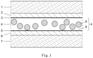
- Fig. 1 schematically shows a vehicle window according to the invention with a first glass pane 1, one or more polymer layers 2, and two electrically conductive layers 3 and 5, which are arranged on either side of the PDLC layer 4.
- the PDLC layer 4 comprises a polymer matrix 9 in which liquid crystal droplets 8 are embedded.
- One or more polymer layers 6 are arranged between the electrically conductive layer 5 and the second glass pane 7.
- the liquid crystal droplets 8 of the PDLC layer 4 have an average size of more than 2 ⁇ m, with a relative standard deviation of more than 30%.
- the one or more polymer layers 2 and 6 can each consist of at least one PVB film as a laminating layer, which faces the first or second glass pane 1, 7, respectively, and at least one polyester film as a protective layer, which faces the respective electrically conductive layer 3, 5.
- additional functional layers e.g., IR-reflecting layers, can be located on the inside of the first glass layer 1 and in the polymer layers 2.
- the electrically conductive layers 3, 5 can be transparent ITO coatings.
- a vehicle window according to the invention with an SPD layer has the same basic structure, except that the PDLC layer 4 is formed by an SPD layer with suspension droplets embedded in the polymer matrix, in which light-polarizing particles are suspended.
- Fig. 2a and 2b show the functionality of the PDLC technology on a vehicle window according to Fig. 1
- the panel is connected to a voltage source V via the two electrically conductive layers 3 and 5.
- the circuit can be closed (ON mode, S') and opened (OFF mode, S).
- ON mode an electric field is applied, the liquid crystals 8 align in an orderly manner, and incident light 10 is hardly scattered, resulting in a transparent PDLC layer and transparent panel ( Fig. 2b ).
- the electric current is switched off, the liquid crystals 8 are randomly aligned, so that incident light 10 is scattered 10' and the PDLC layer and the disc become opaque ( Fig. 2a ).
- the technique is essentially the same for SPD layers, where the suspension droplets are uniformly or randomly oriented.
- the Fig. 1 , 2a and 2b are also purely schematic with regard to the illustrated light refraction.
- the theory of the different refraction of light is as follows.
- the liquid crystal droplets or the suspension droplets are characterized by two different refractive indices ne (in ON mode, S') and n' (in OFF mode, S).
- Light is refracted, when the refractive index of the surrounding polymer matrix np differs from the refractive index of the liquid crystal droplet or the suspension droplet in OFF mode n'.
- Light is not refracted if the refractive indices ne and np match.
- the droplets In OFF mode, the droplets are randomly aligned, the refractive index n' differs from the refractive index np, the light is scattered, and the disc appears cloudy or opaque.
- the liquid crystal molecules adjust themselves at the edge of the liquid crystal droplets.
- the droplets In ON mode, the droplets orient themselves uniformly along the direction of the applied field, with the refractive index ne chosen to roughly match the refractive index np, ensuring high light transmission and thus transmission.
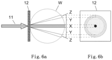
- Fig. 6a-b depict a schematic representation of a corona Y with a rainbow, i.e., the corona and rainbow effect, and how it occurs.
- the results are shown of solar radiation 11 through a vehicle window with a PDLC coating 12.
- the light is scattered in the vehicle window, so that the observer perceives not only the sun in the direct area X, but also a corona Y including the colored rainbow area Z.
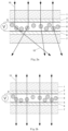
- Fig. 4 shows schematically (not to scale) the microstructure of the PDLC layer 4, containing liquid crystal droplets 8 and polymer matrix 9, of the PDLC film A.
- Fig. 5 shows schematically (not to scale) the microstructure of the PDLC layer 4, containing liquid crystal droplets 8 and polymer matrix 9, of the PDLC film D.
- Vehicle windows were manufactured using PDLC films A, B, C, and D.
- assemblies were formed consisting of, in this order, a first glass pane, a PVB film, the PDLC film, a PVB film, and a second glass pane. These assemblies were laminated to form a laminated glass in the usual way under elevated temperature and pressure.
- the vehicle windows with PDLC films A, B, and C are comparison windows.
- the vehicle window with PDLC film D is according to the invention.
- the vehicle windows were tested for the corona effect.
- the vehicle windows were connected to a voltage source via the electrically conductive layers (electrodes). All vehicle windows exhibited good electro-optical properties, with satisfactory opacity in OFF mode (voltage source off) and transparency in ON mode (voltage source on), although the voltage required for the transparent state was relatively low.
- a strong light source was positioned on one side of the vehicle window while it was transparent. A photograph of the light source was then taken through the window from the other side. The images are shown in the Fig. 3a-d reproduced.
- Fig. 3a shows the image for the vehicle window with PDLC film A.
- the image shows a very wide, clearly blue ring around the light source.
- Fig. 3b shows the image for the vehicle window with PDLC film B.
- the image shows a wide, blue ring around the light source. At the edge of the ring, the color fades and changes to reddish-brown (rainbow effect).
- Fig. 3c shows the image for the vehicle window with PDLC film C.
- the image shows a wide, bluish ring around the light source.
- the width of the corona is roughly comparable, but the colors are less intense.
Landscapes
- Physics & Mathematics (AREA)
- Nonlinear Science (AREA)
- Chemical & Material Sciences (AREA)
- General Physics & Mathematics (AREA)
- Optics & Photonics (AREA)
- Crystallography & Structural Chemistry (AREA)
- Dispersion Chemistry (AREA)
- Mathematical Physics (AREA)
- Liquid Crystal (AREA)
- Electrochromic Elements, Electrophoresis, Or Variable Reflection Or Absorption Elements (AREA)
- Joining Of Glass To Other Materials (AREA)
Description
- Die Erfindung betrifft eine Fahrzeugscheibe, deren Lichtdurchlässigkeit durch Anlegen einer elektrischen Spannung veränderbar ist, insbesondere ist sie zwischen einem transparenten Zustand und einem trüben oder opaken Zustand umschaltbar.
- Solche Scheiben, auch als PDLC-Glas (engl. smart glazing) oder Intelligentes Glas bezeichnet, enthalten eine PDLC-Schicht (PDLC = polymer dispersed liquid crystal) als aktive Schicht, durch die die Scheibe zwischen einem transparenten Zustand und einem trüben oder opaken Zustand umschaltbar ist.
- Die PDLC-Schicht umfasst eine Polymermatrix, in der Flüssigkristalltröpfchen eingebettet sind, die sich zwischen zwei transparenten elektrisch leitenden Schichten (Elektroden) befindet und an die ein elektrisches Feld angelegt werden kann. Ohne elektrisches Feld sind die Flüssigkristalltröpfchen nicht ausgerichtet, was zum trüben oder opaken Zustand der Scheiben führt. Bei Anlegen eines elektrischen Feldes werden die Flüssigkristalltröpfchen in gleicher Richtung ausgerichtet und die die PDLC-Schicht wird transparent. Der Vorgang ist reversibel.
- PDLC-Glas findet z.B. als Fenster für Bauwerke Verwendung. Bei Gebäuden werden in der Regel mehrere dicke Scheiben von z.B. 6 mm verwendet. Üblich sind Systeme mit drei Scheiben, die durch einen Hohlraum separiert sind. PDLC-Schichten können bei solchen Scheiben zwischen einer klassischen Scheibe und einer zusätzlichen Scheibe laminiert werden, auf einer inneren Scheibe aufkaschiert werden oder retrofit auf die Innenseite aufkaschiert werden.
- Scheiben aus PDLC-Glas sind auch für Fahrzeuge interessant, beispielsweise in einem Schiebedach, als Glasdach, als Heckscheibe oder als hintere Seitenscheibe. Im trüben oder opaken Zustand kann die PDLC-Scheibe direkte Sonnenstrahlung abhalten und die Privatsphäre schützen.
- Ein Nachteil bei PDLC-Schichten enthaltenden Fahrzeugscheiben bzw. Scheiben besteht aber darin, dass sich im transparenten Zustand der Scheibe ein relativ starker Coronaeffekt ausbilden kann, wenn Licht einer Lichtquelle, gewöhnlich die Sonne, durch die Scheibe fällt. Hierbei bildet sich ein als Corona bezeichnetes konzentrisches Ringmuster um die Lichtquelle. Der zentrale helle Bereich der Corona, auch als Aureole bezeichnet, sieht wie eine bläulich-weiße Scheibe aus, die zum Rand hin zu rötlich braun verblasst. Am äußeren Rand der Corona nimmt der Betrachter mitunter die Farben des Regenbogens wahr, was auch als Regenbogeneffekt bezeichnet wird. Bei Fahrzeugscheiben spielen diese Effekte aufgrund des geringen Betrachterabstands und der für Fahrzeuge häufig gewünschten Tönung der Scheibe eine ausgeprägte Rolle. Bei anderen Anwendungen von Scheiben mit PDLC-Schichten, z.B. als Fenster in Bauwerken, sind die Effekte eher vernachlässigbar.
- Wenn der Betrachter einen weiten Abstand von der Fahrzeugscheibe hat, ist die Corona weniger sichtbar. Der Coronaeffekt im transparenten Zustand der Fahrzeugscheibe ist aber ausgeprägt, wenn der Betrachter sich nahe an der PDLC-Scheibe befindet. Der Effekt ist sogar noch stärker, wenn die PDLC-Scheibe geneigt ist. Für Fahrzeuginsassen ist der Effekt daher störend, da sie sich nahe an der Fahrzeugscheibe, z.B. einem Schiebedach, befinden. Beim Blick durch ein Schiebedach oder Glasdach in Richtung Sonne ist zudem der Blickwinkel geneigt, was die Situation weiter verschärft. Die Farberscheinungen der Corona wirken für die Fahrzeuginsassen ebenfalls störend.
- Eine andere bekannte Technik zur Bereitstellung von Scheiben, die zwischen einem transparenten Zustand und einem trüben oder opaken Zustand umschaltbar sind, ist die SPD-Technologie, bei der eine SPD-Schicht (SPD = suspended particle device) als aktive Schicht in der Scheibe enthalten ist. Bei SPD-Schichten wird in der Regel kein opaker Zustand erreicht. Das Prinzip ist ähnlich wie bei den PDLC-Schichten, außer dass bei der SPD-Schicht nicht Flüssigkristalltröpfchen, sondern Suspensionströpfchen, in denen Licht polarisierende Partikel suspendiert sind, in einer Polymermatrix eingebettet sind. Solche Systeme werden z.B. in der
EP 0551138 A1 beschrieben. Auch bei SPD-Schichten enthaltenden Scheiben werden im transparenten Zustand die vorstehend erwähnten Corona- und gegebenenfalls Regenbogeneffekte in gleicher Weise beobachtet. -
WO 2016/008375 A1 betrifft eine schaltbare Glasstruktur, bei der zwischen einem ersten Glas und einem zweiten Glas eine PDLC-Schicht angeordnet ist, die eine Polymerschicht und darin dispergierte Flüssigkristallmikrokugeln umfasst, wobei das erste und/oder zweite Glas mit einer Strahlenschutzbeschichtung versehen ist. -
DE 102013214249 A1 beschreibt die Herstellung eines Folienverbunds, bei dem es sich um eine PDLC-Folie oder eine SPD-Folie handeln kann. -
DE 202013006516 U1 betrifft ein System mit einer zwischen zwei Elektroden befindlichen PDLC-Schicht, die eine Flüssigkristallmischung enthält, die in einer Polymermatrix dispergierte Mikrotröpfchen formt, wobei der Massenanteil der Flüssigkristallmischung zwischen 40 und 70% liegt, die PDLC-Schicht eine Dicke zwischen 5 und 25 µm hat und der mittlere Durchmesser der in der Polymermatrix dispergierten Flüssigkristalltröpfchen zwischen 0,25 µm und 2,00 µm liegt. - Der Erfindung liegt daher die Aufgabe zu Grunde, eine Fahrzeugscheibe der eingangs genannten Art mit einer PDLC-Schicht oder einer SPD-Schicht bereitzustellen, die einen abgeschwächten Coronaeffekt und gegebenenfalls auch einen abgeschwächten Regenbogeneffekt zeigt oder bei der diese Effekte weitgehend beseitigt sind.
- Erfindungsgemäß wird diese Aufgabe durch eine Fahrzeugscheibe nach Anspruch 1 gelöst. Die Erfindung betrifft gemäß den weiteren unabhängigen Ansprüchen auch ein Fahrzeug, dass eine solche Scheibe umfasst, und die Verwendung der erfindungsgemäßen Scheibe als Fahrzeugscheibe. Bevorzugte Ausgestaltungen der Erfindung sind in den abhängigen Ansprüchen wiedergegeben.
- Die Erfindung betrifft somit eine Fahrzeugscheibe, die in dieser Reihenfolge umfasst:
- 1. a. eine erste Glasscheibe (1),
- 2. b. eine oder mehrere Polymerschichten (2),
- 3. c. eine PDLC-Schicht (4), umfassend eine Polymermatrix (9), in die Flüssigkristalltröpfchen (8) eingebettet sind, wobei auf den beiden Seiten der PDLC-Schicht jeweils eine elektrisch leitfähige Schicht (3, 5) angeordnet ist, oder eine SPD-Schicht, umfassend eine Polymermatrix, in der Suspensionströpfchen, in denen Licht polarisierende Teilchen suspendiert sind, eingebettet sind, wobei auf den beiden Seiten der SPD-Schicht jeweils eine elektrisch leitfähige Schicht angeordnet ist,
- 4. d. eine oder mehrere Polymerschichten (6) und
- 5. e. eine zweite Glasscheibe (7),
- Die erfindungsgemäße Fahrzeugscheibe zeigt gegenüber PDLC-Schichten oder SPD-Schichten enthaltenden Fahrzeugscheiben nach dem Stand der Technik einen deutlich abgeschwächten Coronaeffekt. Die Größe bzw. der Durchmesser der Corona ist deutlich verringert. Die optische Qualität der Scheiben wird verbessert. Störende Effekte für die Fahrzeuginsassen werden dadurch vermieden oder zumindest verringert.
- Da die Flüssigkristalltröpfchen oder Suspensionströpfchen eine durchschnittliche Größe von mehr als 2 µm mit einer relativen Standardabweichung von mehr als 30% aufweisen, nimmt auch der Kontrast zwischen den Farben in der Corona und im Regenbogenbereich deutlich ab und die Farben verblassen (Regenbogeneffekt). Dies verbessert die optische Qualität der Scheiben noch weiter.
- Durch die Einstellung der Größe der Flüssigkristalltröpfchen oder Suspensionströpfchen in einem größeren Bereich verringert sich die Größe der Corona. Durch den Einsatz von Flüssigkristalltröpfchen oder Suspensionströpfchen mit einer recht großen Standardabweichung, also einer inhomogenen Teilchengrößenverteilung, verringert sich der Kontrast zwischen den Farben in der Corona, so dass die Farben verblassen und gegebenenfalls völlig verschwinden.
- Die Erfindung wird im Folgenden und anhand der beigefügten Figuren erläutert. In diesen zeigt:
- Fig. 1
- eine schematische Darstellung einer erfindungsgemäßen Fahrzeugscheibe mit PDLC-Schicht;
- Fig. 2a-b
- eine schematische Darstellung einer Fahrzeugscheibe mit PDLC-Schicht im trüben bzw. opaken Zustand (
Fig. 2a ) und im transparenten Zustand (Fig. 2b ); - Fig. 3a-d
- Fotographien der Sonne durch nicht erfindungsgemäße Fahrzeugscheiben (
Fig. 3a-c ) und eine erfindungsgemäße Fahrzeugscheibe (Fig. 3d ); - Fig. 4
- eine schematische Darstellung der Mikrostruktur einer PDLC-Schicht im Querschnitt;
- Fig. 5
- eine schematische Darstellung der Mikrostruktur einer anderen PDLC-Schicht im Querschnitt;
- Fig. 6a-b
- eine schematische Darstellung des Corona- und des Regenbogeneffekts.
- Die erfindungsgemäßen Fahrzeugscheiben bzw. die PDLC-Schicht oder SPD-Schicht sind reversibel zwischen einem transparenten Zustand und einem trüben oder opaken Zustand umschaltbar, d.h. die Lichtstreuung der Scheibe kann variabel eingestellt werden. Hierfür wird die Fahrzeugscheibe über die elektrisch leitfähigen Schichten mit einer ein- und ausschaltbaren Spannungsquelle verbunden.
- Bei dem trüben oder opaken Zustand ist die Lichtdurchlässigkeit reduziert, so dass die Fahrzeugscheibe opak, d.h. undurchsichtig, oder trübe, d.h. vermindert durchsichtig, wird.
- Wird durch Einschalten der Spannungsquelle ein elektrisches Feld angelegt, so richten sich die Flüssigkristalltröpfchen der PDLC-Schicht bzw. die Suspensionströpfchen der SPD-Schicht aus und die PDLC-Schicht bzw. SPD-Schicht wird transparent, also durchsichtig. Wird die Spannungsquelle abgeschaltet, so dass kein elektrisches Feld vorhanden ist, sind die Flüssigkristalltröpfchen der PDLC-Schicht bzw. die Suspensionströpfchen nicht gleichartig ausgerichtet, das Licht wird gestreut und die PDLC-Schicht bzw. SPD-Schicht ist trübe oder opak. Der Vorgang ist reversibel. Das Prinzip wird anhand der
Fig. 2a-b nachstehend weiter erläutert. - Fensterscheiben, welche eine PDLC-Schicht (PDLC = polymer dispersed liquid crystal) oder eine SPD-Schicht (SPD = suspended particle device) aufweisen und reversibel zwischen einem transparenten Zustand und einem trüben oder opaken Zustand umschaltbar sind, sind bekannt.
- Der vorstehend beschriebene Coronaeffekt bei PDLC- und SPD-Schichten beim Betrachten einer Lichtquelle wie der Sonne durch die Scheibe entsteht durch eine Streuung des Lichts an den Flüssigkristalltröpfchen bzw. Suspensionströpfchen in der Fensterscheibe. In
Fig. 6 ist der Effekt schematisch dargestellt. Ein ähnlicher Effekt ist auch in der Meteorologie bekannt, wenn Sonnen- oder Mondlicht von Wassertröpfchen in Wolken gestreut wird. - Die erfindungsgemäße Fahrzeugscheibe weist eine PDLC-Schicht oder eine SPD-Schicht auf. Die PDLC-Schicht umfasst oder ist eine Polymermatrix, in die Flüssigkristalltröpfchen eingebettet sind, wobei die Flüssigkristalltröpfchen eine durchschnittliche Größe von mehr als 2 µm aufweisen, wobei die relative Standardabweichung der durchschnittlichen Größe mehr als 30% beträgt. Bei den Flüssigkristalltröpfchen handelt es sich um flüssige Tröpfchen von einer oder mehreren Flüssigkristallverbindungen. Die SPD-Schicht umfasst oder ist eine Polymermatrix, in der Suspensionströpfchen, in denen Licht polarisierende Teilchen suspendiert sind, eingebettet sind, wobei die Suspensionströpfchen eine durchschnittliche Größe von mehr als 2 µm aufweisen, wobei die relative Standardabweichung der durchschnittlichen Größe mehr als 30% beträgt. Bei den Suspensionströpfchen handelt es sich um Tröpfchen einer Suspensionsflüssigkeit, in die Licht polarisierende Partikel suspendiert sind.
- Die durchschnittliche Größe der Flüssigkristalltröpfchen oder der Suspensionströpfchen kann z.B. bis zu 30 µm betragen, beträgt aber bevorzugt nicht mehr als 12 µm. In einer bevorzugten Ausführungsform beträgt die durchschnittliche Größe der Flüssigkristalltröpfchen oder der Suspensionströpfchen 3 bis 10 µm, bevorzugter 4 bis 8 µm. Dies ist bezüglich einer weiter verringerten Corona von Vorteil. Die relative Standardabweichung der durchschnittlichen Größe der Flüssigkristalltröpfchen oder der Suspensionströpfchen beträgt bevorzugt mehr als 30% und nicht mehr als 80%.
- Die durchschnittliche Größe bezieht sich hier auf den arithmetischen Mittelwert. Die relative Standardabweichung als Maß für die Tröpfchengrößenverteilung ist hier wie üblich der in Prozent angegebene Quotient aus Standardabweichung des arithmetischen Mittelwerts und dem arithmetischen Mittelwert. Die relative Standardabweichung wird auch als Variationskoeffizient bezeichnet.
- Die durchschnittliche Größe und die Standardabweichung der Flüssigkristalltröpfchen in der PDLC-Schicht bzw. der Suspensionströpfchen in der SPD-Schicht sind hier die durchschnittliche Größe und Standardabweichung, die durch Messen der Durchmesser von mindestens 50 Flüssigkristalltröpfchen bzw. Suspensionströpfchen in einer Rasterelektronenmikroskop (REM)-Aufnahme von einem Querschnitt der PDLC-Schicht bzw. der SPD-Schicht und durch Berechnen des arithmetischen Mittels der an der Aufnahme gemessenen Durchmesser und der Standardabweichung bestimmt wird. Wenn die Tröpfchen in der Aufnahme nicht kugelförmig sind, wird der Hauptachsendurchmesser (größter Durchmesser) gewählt. Anzumerken ist, dass die Flüssigkristalltröpfchen bzw. Suspensionströpfchen mesogene Flüssigkeiten sind, die beim Erstellen der Querschnitte der PDLC-Schicht bzw. der SPD-Schicht aus der Polymermatrix auslaufen, so dass tatsächlich die in der Polymermatrix verbleibenden Hohlräume vermessen werden, die der Form und Größe der ausgelaufenen Tröpfchen entsprechen.
- Die Flüssigkristalltröpfchen der PDLC-Schicht können eine oder mehrere Flüssigkristall-Verbindungen enthalten. Es können übliche Flüssigkristalle eingesetzt werden. Es gibt eine Reihe von unterschiedlichen Systemen, die im Handel erhältlich sind. Beispiele für geeignete Flüssigkristalle sind z.B. in
EP 0 564 869 A1 undEP 0 598 086 A1 beschrieben. Ebenfalls geeignet ist z.B. das von der Firma Merck unter der Bezeichnung MDA-00-3506 vertriebene Produkt, das eine Mischung von 4-((4-Ethyl-2,6-difluorphenyl)-ethinyl)-4'-propylbiphenyl und von 2-Fluor-4,4'-bis-(trans-4-propylcyclohexyl)-biphenyl enthält. In einer bevorzugten Ausführungsform sind die Flüssigkristalltröpfchen bei Umgebungstemperatur (23°C) nematisch. Gegebenenfalls weisen sie ferner eine positive dielektrische Anisotropie auf. - In einer bevorzugten Ausführungsform beträgt der Anteil an Flüssigkristalltröpfchen in der PDLC-Schicht, bezogen auf die Gesamtmasse an Flüssigkristalltröpfchen und Polymer der Polymermatrix, 40-70 Gew.-%, bevorzugter 50-70 Gew.-%. Neben den Flüssigkristalltröpfchen und der Polymermatrix kann die PDLC-Schicht weitere Bestandteile enthalten, z.B. Abstandshalter aus einem nichtleitenden Material aus Glas oder Kunststoff. Die Abstandshalter sind bevorzugt transparent.
- Die Suspensionströpfchen der SPD-Schicht umfassen Tröpfchen einer flüssigen Suspension, in denen Licht polarisierende Partikel suspendiert sind. Solche Systeme werden z.B. in der
EP 0551138 A1 beschrieben. - Die folgenden Angaben zur Polymermatrix gelten sowohl für die Polymermatrix der PDLC-Schicht als auch für die Polymermatrix der SPD-Schicht, sofern nicht anders angegeben. Die Polymermatrix ist bevorzugt transparent. Die Polymermatrix wird bevorzugt durch thermische Polymerisation oder Photopolymerisation erhalten. Die Polymermatrix kann z.B. aus einem Polymer von einem oder mehreren Vinyl- oder (Meth)acrylat-Monomeren und gegebenenfalls Vinyl- oder (Meth)acrylat-Oligomeren, einem Epoxidharz oder einem Urethanharz gebildet sein. Die Polymermatrix ist bevorzugt eine (Meth)acrylat-Polymermatrix. (Meth)acrylat steht für Acrylat und/oder Methacrylat. Beispiele für Vinyl- oder (Meth)acrylat-Monomere und Oligomere davon sind Mono(meth)acrylate, Di(meth)acrylate, N-substituierte Acrylamide, N-Vinylpyrrolidone, Styrol und seine Derivate, Vinylchlorid, Polyester(meth)acrylate, Epoxy(meth)acrylate, Polyurethan(meth)acrylate und Polyether(meth)acrylate.
- Vorzugsweise ist die Polymermatrix das Polymer von mindestens einer monofunktionellen Vinylverbindung, vorzugsweise eines Acrylatmonomers oder eines Methacrylatmonomers, mindestens einer difunktionellen Vinylverbindung, vorzugsweise eines Diacrylatmonomers oder eines Dimethacrylatmonomers, und gegebenenfalls mindestens eines mono-, di- oder polyfunktionellen Vinyloligomers, vorzugsweise eines Acrylatoligomers oder eines Methacrylatoligomers.
- Eine geeignete Monomermischung zur Herstellung der Polymermatrix umfasst z.B. 30-95 Gew.-% mindestens eines monofunktionellen (Meth)acrylat-Monomers, 1-60 Gew.-% mindestens eines difunktionellen (Meth)acrylat-Monomers und 1-50 Gew.-% mindestens eines mono-, di- oder polyfunktionellen (Meth)acrylatOligomers, bezogen auf das Gesamtgewicht der Monomere und Oligomere.
- Verschiedene Techniken sind entwickelt worden, um eine PDLC-Schicht mit einer Polymermatrix mit darin eingebetteten Flüssigkristalltröpfchen zu erhalten, die in Abhängigkeit von den eingesetzten Materialien verwendet werden. Zu diesen Techniken gehören thermisch induzierte Phasentrennung (TIPS), Lösungsmittel-induzierte Phasentrennung (SIPS) und Polymerisations-induzierte Phasentrennung (PIPS). Bei der PIPS kann die Polymerisation thermisch oder photochemisch, z.B. durch UV-Strahlung, induziert werden. PIPS ist im allgemeinen die bevorzugte Technik.
- Wenn ein Polymer-Vorstufenmaterial wie die vorstehend genannten Monomere, Oligomere oder Harze mit einer Flüssigkristallverbindung mischbar ist, kann die Polymerisations-induzierte Phasentrennung (PIPS) verwendet werden. Nach homogener Mischung von Flüssigkristall und Polymer-Vorstufenmaterial wird die Polymerisation initiiert, um die Phasentrennung zu induzieren. Bei der Polymerisation nimmt die Löslichkeit des Flüssigkristalls in dem wachsenden Polymernetzwerk ab, bis sich wachsende Flüssigkristalltröpfchen in der sich bildenden Matrix bilden und das Polymer zu gelieren beginnt. Tröpfchengröße, die Größenverteilung und die Morphologie der Tröpfchen werden während der Zeit zwischen der Tröpfchenbildung und dem Gelieren des Polymers bestimmt. Wichtige Faktoren sind die Polymerisationsrate, die relativen Konzentrationen von Materialien, die Temperatur, die Typen an Flüssigkristall und verwendeten Polymere und verschiedene andere physikalische Parameter, wie etwa Viskosität, Löslichkeit des Flüssigkristalls in dem Polymer.
- Die thermisch induzierte Phasentrennung (TIPS) kann für Flüssigkristallmaterialien und thermoplastische Materialien verwendet werden, die in der Lage sind, eine homogene Lösung oberhalb der Schmelztemperatur des Polymers zu bilden. Die homogene Lösung des Flüssigkristalls in der thermoplastischen Schmelze wird unterhalb des Schmelzpunkts des thermoplastischen Materials gekühlt, wodurch eine Phasentrennung des Flüssigkristalls bewirkt wird. Die Tröpfchengröße und Verteilung des Flüssigkristalls kann z.B. durch die Kühlrate und Material-Parameter eingestellt werden.
- Bei der Lösungsmittel-induzierte Phasentrennung (SIPS) werden Flüssigkristall und ein thermoplastisches Material in einem Lösungsmittel gelöst. Die darauffolgende Verdampfung des Lösungsmittels führt zu einer Phasentrennung des Flüssigkristalls, Tröpfchenbildung und Wachstum und Polymer-Gelierung.
- Die PDLC-Schicht kann z.B. eine Dicke von 5 bis 40 µm, bevorzugt von 10 bis 25 µm aufweisen. Die SPD-Schicht kann z.B. eine Dicke von 50 bis 150 µm, bevorzugt von 80 bis 110 µm aufweisen.
- Die folgenden Angaben zur elektrisch leitfähigen Schicht gelten sowohl für die elektrisch leitfähigen Schichten, die auf beiden Seiten der PDLC-Schicht angeordnet sind, als auch für die, die auf beiden Seiten der SPD-Schicht angeordnet sind, sofern nicht anders angegeben. Die elektrisch leitfähigen Schichten sind bevorzugt transparent. Die elektrisch leitfähigen Schichten bilden Elektroden, die mit der PDLC-Schicht bzw. der SPD-Schicht in Kontakt sind und in der erfindungsgemäßen Scheibe so konfiguriert sind, dass sie mit einer Spannungsquelle verbunden werden können.
- Die elektrisch leitende Schicht kann transparente, leitende Oxide (TCO) enthalten, also Materialien, die sowohl gut leitend als auch im sichtbaren Licht transparent sind. Beispiele sind mit Zinn dotiertes Indiumoxid (ITO), mit Antimon oder Fluor dotiertes Zinnoxid (SnO2:F) oder mit Aluminium dotierte Zinkoxid (ZnO: Al), wobei ITO bevorzugt ist. Eine elektrisch leitende Schicht auf der Basis von ITO kann z.B. einen Oberflächenwiderstand von 50 bis 200 Ohm pro Quadrat aufweisen.
- Die Dicke der elektrisch leitenden Schichten auf Basis dieser transparenten leitenden Oxide (TCO) liegt bevorzugt im Bereich von 50 bis 100 nm. Bekannte Beschichtungstechniken sind z.B. durch ein Magnetfeld unterstützte Kathodenzerstäubung, Verdunstung, Sol-Gel-Verfahren oder Gasphasenabscheidung (CVD).
- Die elektrisch leitende Schicht kann auch eine Metallschicht sein, vorzugsweise eine Dünnschicht oder ein Stapel von Dünnschichten. Geeignete Metalle sind z.B. Ag, Al, Pd, Cu, Pd, Pt In, Mo, Au. Diese Metallbeschichtungen werden als TCC (transparent conductive coating) bezeichnet. Typische Dicken der Einzelschichten liegen im Bereich von 2 bis 50 nm.
- Eine große Vielfalt an PDLC-Schichten und SPD-Schichten, die jeweils elektrisch leitende Schichten auf der Oberseite und Unterseite aufweisen, ist im Handel erhältlich. In der Regel sind die beiden elektrisch leitenden Schichten der PDLC-Schicht und der SPD-Schicht auf einem Substrat bestehend aus Polymerfolien aufgebracht. Bei den Polymerfolien kann es sich z.B. um Polyesterfolien, bevorzugt Polyethylenterephthalat (PET)-Folien, handeln. Ein solcher Verbund kann für den Einbau in die erfindungsgemäße Fahrzeugscheibe eingesetzt werden.
- Die erfindungsgemäße Fahrzeugscheibe ist eine Verbundglasscheibe, in die die PDLC-Schicht bzw. die SPD-Schicht als funktionelle Schicht enthalten ist. Daneben umfasst die Fahrzeugscheibe eine erste und eine zweite Glasscheibe, die durch eine oder mehrere Polymerfolien auf beiden Seiten der funktionellen Schicht zu einem festen Verbund laminiert sind.
- Die erste Glasscheibe und die zweite Glasscheibe können aus dem gleichen Material oder aus verschiedenem Material sein. Die Scheiben können aus anorganischem Glas und/oder organischem Glas (Polymere) sein. In einer bevorzugten Ausführungsform enthält die erste Glasscheibe und/oder die zweite Glasscheibe Glas und/oder Polymere, bevorzugt Flachglas, Quarzglas, Borosilikatglas, Kalk-Natron-Glas, Alkalialuminosilikatglas, Polycarbonat und/oder Polymethacrylat.
- Die erste Glasscheibe und die zweite Glasscheibe können die gleiche Dicke oder unterschiedliche Dicken aufweisen. Bevorzugt weisen die erste Glasscheibe und die zweite Glasscheibe unabhängig voneinander eine Dicke im Bereich von 0,4 bis 4,0 mm, z.B. 0,4 bis 3,85 mm, bevorzugter 1,6 bis 2,5 mm, auf. Aus mechanischen Gründen ist die Außenscheibe bevorzugt dicker oder gleich dick wie die innere Scheibe. Die Innenscheibe ist die Glasscheibe, die beim Einbau in das Fahrzeug zum Innenraum des Fahrzeugs zeigt, während die Außenscheibe nach außen zeigt.
- Zwischen erster Glasscheibe und PDLC-Schicht bzw. SPD-Schicht und zwischen zweiter Glasscheibe und PDLC-Schicht bzw. SPD-Schicht befinden sich je eine oder mehrere Polymerschichten. Die folgenden Angaben beziehen sich unabhängig voneinander auf alle diese eine oder mehrere Polymerschichten, sofern nicht anders angegeben. In der Regel werden als Ausgangsmaterial zur Bildung der Polymerschichten entsprechende handelsübliche Polymerfolien eingesetzt. Vorzugsweise enthält mindestens eine der einen oder mehreren Polymerschichten ein thermoplastisches Polymer. Die eine oder mehrere Polymerschichten sind bevorzugt transparent, farblos oder getönt.
- Die eine oder mehreren Polymerschichten können als Laminierschicht z.B. Polyvinylbutyral, Ethylenvinylacetat, Polyurethan, Polypropylen, Polyacrylat, Polyethylen, Polycarbonat, Polymethylmetacrylat, Polyvinylchlorid, Polyacetatharz, Gießharz, Acrylat, fluoriniertes Ethylen-Propylen, Polyvinylfluorid und/oder Ethylen-Tetrafluorethylen und/oder ein Gemisch und/oder ein Copolymer davon enthalten.
- Vorzugsweise enthält mindestens eine der einen oder mehreren Polymerschichten als Laminierschicht Polyvinylbutyral (PVB), Ethylenvinylacetat, Polyurethan, und/oder Gemische davon und/oder Copolymere davon, wobei Polyvinylbutyral bevorzugt ist.
- Die eine oder mehreren Polymerschichten können neben den vorstehend genannten polymeren Laminierschichten gegebenenfalls zusätzliche Polymerschichten mit anderer Funktion enthalten, z.B. als Schutzschicht für die PDLC-Schicht bzw. SPD-Schicht mit den darüber und darunter angeordneten elektrisch leitenden Schichten. Die Schutzschicht kann z.B. eine Polyesterschicht, bevorzugt eine Polyethylenterephthalat (PET)-Schicht, sein. Weitere Beispiele für Polymerschichten für bestimmte Funktionen sind getönte PVB-Folien, Akustikfolien und IR-reflektierende PET-Folien bzw. die daraus gebildeten Schichten. Sofern neben der oder den Laminierschichten weitere Polymerschichten enthalten sind, sind die Polymerschichten, die am nächsten zur ersten und zweiten Glasscheibe angeordnet sind, im allgemeinen polymere Laminierschichten.
- Die eine oder mehreren Polymerschichten weisen z.B. jeweils eine Dicke von 0,04 bis 1,5 mm, bevorzugt 0,1 bis 1,5 mm, bevorzugter von 0,3 bis 0,9 mm auf, typischerweise 0,38 mm, 0,76 mm oder 0,85 mm. Die Dicke der Schichten kann je nach Verwendungszweck variieren. In einigen Ausführungsformen können z.B. PET-Schichten mit einer Dicke von 0,05 mm und/oder Akustik-Folien mit einer Dicke von 0,85 mm eingesetzt werden. Die als Laminierschichten eingesetzten Polymerschichten weisen bevorzugt eine Dicke von 0,1 bis 1,5 mm, bevorzugter von 0,3 bis 0,9 mm, auf.
- In einer bevorzugten Ausführungsform umfasst die Fahrzeugscheibe in dieser Reihenfolge die erste Glasscheibe, mindestens eine Laminierschicht als erste Polymerschicht, z.B. eine PVB-Schicht, mindestens eine Schutzschicht als zweite Polymerschicht, die PDLC-Schicht mit den beiden elektrisch leitfähigen Schichten auf der Unter- und Oberseite oder die SPD-Schicht mit den beiden elektrisch leitfähigen Schichten auf der Unter- und Oberseite, mindestens eine Schutzschicht als zweite Polymerschicht, mindestens eine Laminierschicht als erste Polymerschicht, z.B. eine PVB-Schicht, und die zweite Glasscheibe.
- In einer Ausführungsform kann die Fahrzeugscheibe getönt sein und/oder mindestens ein beschichtetes Glas als erste und/oder zweite Glasscheibe umfassen. Dadurch können die optischen Eigenschaften der Fahrzeugscheibe modifiziert werden. Eine getönte Fahrzeugscheibe kann durch Einsatz getönter Glasscheiben und/oder getönter Polymerschichten erhalten werden. In der erfindungsgemäßen Fahrzeugscheibe ist dann mindestens eine Glasscheibe ausgewählt aus der ersten und zweiten Glasscheibe eine getönte Glasscheibe und/oder mindestens eine Polymerschicht ausgewählt aus der einen oder den mehreren Polymerschichten zwischen der ersten Glasscheibe und der PDLC-Schicht oder SPD-Schicht und der einen oder den mehreren Polymerschichten zwischen der zweiten Glasscheibe und der PDLC-Schicht oder SPD-Schicht eine getönte Polymerschicht. Für getönte Polymerschichten können z.B. getönte PVB-Folien und/oder IR-reflektierende PET-Folien verwendet werden. Ein Beispiel für beschichtetes Glas ist Low-E-Glas (Low-Emissivity-Glas) oder Glas mit einer IR-reflektierenden Beschichtung. Low-E-Gläser sind im Handel erhältlich und mit einer oder mehreren Metallschichten beschichtet.
- Die Metallbeschichtung ist sehr dünn, z.B. weist sie eine Dicke von etwa 100 nm auf. Bei Einsatz einer beschichteten Glasscheibe als erster und/oder zweiter Glasscheibe befindet sich die Beschichtung vorzugsweise auf der Innenseite der Glasscheibe relativ zur Fahrzeugscheibe.
- Es versteht sich, dass bei einer getönten Fahrzeugscheibe die Scheibe im transparenten Zustand der PDLC-Schicht bzw. SPD-Schicht getönt ist.
- In einer bevorzugten Ausführungsform ist die PDLC-Schicht bzw. die SPD-Schicht seitlich mit einer Klebedichtmasse und/oder einen Thermoplaststreifen abgedichtet. Vorteilhaft ist, dass die Klebedichtmasse und/oder der Thermoplaststreifen die PDLC-Schicht bzw. die SPD-Schicht vor Korrosion schützt. Es versteht sich, dass seitlich sich auf die Seitenflächen der PDLC- bzw. SPD-Schicht im Gegensatz zu der Ober- und Unterseite der PDLC- bzw. SPD-Schicht bezieht.
- Die Klebedichtmasse kann z.B. ein Polyvinylbutyral (PVB)-Klebedichtmasse und/oder in Form eines Bilderrahmens ausgearbeitet sein. Bei der Bilderrahmentechnik reicht die PDLC-Schicht bzw. die SPD-Schicht nicht bis zum Rand der Fahrzeugscheibe, d.h. sie ist flächenmäßig kleiner als die erste und zweite Glasscheibe und die Polymerschichten. Der freibleibende Rand wird umlaufend durch die Klebdichtmasse versiegelt, die dieselbe Dicke wie die PDLC-Schicht bzw. SPD-Schicht aufweist und so auch als Spacer fungiert. Auf diese Weise ist die PDLC-Schicht bzw. SPD-Schicht seitlich von der Klebedichtmasse umrahmt.
- Bei dem Thermoplaststreifen handelt es sich um ein Band ohne Klebstoff, das umlaufend an den Seitenflächen der PDLC-Schicht bzw. SPD-Schicht U-förmig angebracht wird, so dass die Schenkel des Us auf der Ober- und Unterseite der PDLC-Schicht bzw. SPD-Schicht liegen.
- Die erfindungsgemäße Fahrzeugscheibe eignet sich für alle Fahrzeuge, z.B. Kraftfahrzeuge, Züge, Schiffs- oder Luftfahrzeuge, wobei Kraftfahrzeuge besonders bevorzugt sind. Beispiele für geeignete Kraftfahrzeuge sind Busse, Traktoren, Lastkraftwagen und Personenkraftwagen, wobei Personenkraftwagen besonders bevorzugt sind.
- Die Erfindung betrifft auch ein Fahrzeug, umfassend mindestens eine erfindungsgemäße Fahrzeugscheibe, wobei das Fahrzeug bevorzugt ein Kraftfahrzeug ist. Geeignete und bevorzugte Fahrzeuge sind vorstehend genannt. Die Erfindung betrifft ferner die Verwendung einer erfindungsgemäßen Scheibe als Fahrzeugscheibe, bevorzugt in einem Schiebedach, als Glasdach, als Heckscheibe, als Himmelkante im B-Feld eine Windschutzscheibe oder als vordere oder hintere Seitenscheibe, vorzugsweise in einem Kraftfahrzeug. Auch der Einsatz als Frontscheibe ist denkbar.
- Die erfindungsgemäße Fahrzeugscheibe eignet sich zur Reduzierung des Coronaeffekts und gegebenenfalls des Regenbogeneffekts im transparenten Zustand der Fahrzeugscheibe, die sich ergeben können, wenn ein Betrachter durch die Scheibe in Richtung einer Lichtquelle wie der Sonne blickt.
- Die Erfindung wird nachfolgend anhand von nicht einschränkenden Ausführungsbeispielen unter Bezug auf die beigefügten Zeichnungen weiter erläutert.
Fig. 1 und denFig. 2a-b sind schematische Zeichnungen, was auch für die Wiedergabe der Flüssigkristalltröpfchen gilt, Größe und Größenverteilung der Tröpfchen sind nicht gezeigt. -
Fig. 1 zeigt schematisch eine erfindungsgemäße Fahrzeugscheibe mit erster Glasscheibe 1, einer oder mehrerer Polymerschichten 2 und zwei elektrisch leitfähigen Schichten 3 und 5, welche auf den beiden Seiten der PDLC-Schicht 4 angeordnet sind. Die PDLC-Schicht 4 umfasst eine Polymermatrix 9, in die Flüssigkristalltröpfchen 8 eingebettet sind. Zwischen der elektrisch leitfähigen Schicht 5 und der zweiten Glasscheibe 7, sind eine oder mehrere Polymerschichten 6 angeordnet. Bei der erfindungsgemäßen Ausführungsform weisen die Flüssigkristalltröpfchen 8 der PDLC-Schicht 4 eine durchschnittliche Größe von mehr als 2 µm auf, mit einer relativen Standardabweichung von mehr als 30%. Die einen oder mehreren Polymerschichten 2 und 6 können jeweils aus mindestens einer PVB-Folie als Laminierschicht, die der ersten bzw. zweiten Glasscheibe 1, 7 zugewandt ist, und mindestens einer Polyesterfolie als Schutzschicht, die der jeweiligen elektrisch leitfähigen Schicht 3, 5 zugewandt ist, bestehen. Insbesondere auf der Innenseite der ersten Glasschicht 1 und in den Polymerschichten 2 können sich weitere Funktionsschichten befinden, z.B. IR-reflektierende Schichten. Die elektrisch leitfähigen Schichten 3, 5 können transparente ITO-Beschichtungen sein. Eine erfindungsgemäße Fahrzeugscheibe mit einer SPD-Schicht weist den gleichen prinzipiellen Aufbau aus, außer dass die PDLC-Schicht 4 durch eine SPD-Schicht mit in der Polymermatrix eingebettete Suspensionströpfchen, in die Licht polarisierende Partikel suspendiert sind, enthält. -
Fig. 2a und 2b zeigen die Funktionsweise der PDLC-Technik an einer Fahrzeugscheibe gemäßFig. 1 . Die Scheibe wird dabei über die beiden elektrisch leitfähigen Schichten 3 und 5 mit einer Spannungsquelle V verbunden. Mit Hilfe eines Schalters S/S' kann der Stromkreis geschlossen (ON-Modus, S') und geöffnet (OFF-Modus, S) werden. Im ON-Modus wird ein elektrisches Feld angelegt, die Flüssigkristalle 8 richten sich geordnet aus und einfallendes Licht 10 wird kaum gestreut, was zu einer transparenten PDLC-Schicht und transparenten Scheibe führt (Fig. 2b ). Wenn der elektrische Strom abgeschaltet ist, sind die Flüssigkristalle 8 zufällig ausgerichtet, so dass einfallendes Licht 10 gestreut wird 10' und die PDLC-Schicht und die Scheibe opak bzw. undurchsichtig werden (Fig. 2a ). Die Technik ist bei SPD-Schichten im Prinzip gleich, wobei dort die Suspensionströpfchen gleichmäßig oder willkürlich orientiert sind. - Die
Fig. 1 ,2a und 2b sind auch hinsichtlich der dargestellten Lichtbrechung rein schematisch. Die Theorie zur verschiedenen Brechung des Lichts ist wie folgt. Die Flüssigkristalltröpfchen bzw. die Suspensionströpfchen sind durch zwei verschiedene Brechungsindices ne (im ON-Modus, S') und n' (im OFF-Modus, S) charakterisiert. Licht wird gebrochen, wenn der Brechungsindex der umgebenden Polymermatrix np sich von dem Brechungsindex des Flüssigkristalltröpfchens bzw. des Suspensionströpfchens im OFF-Modus n' unterscheidet. Licht wird nicht gebrochen, wenn die Brechungsindices ne und np übereinstimmen. Im OFF-Modus sind die Tröpfchen zufällig ausgerichtet, der Brechungsindex n' unterscheidet sich von dem Brechungsindex np, das Licht wird gestreut und die Scheibe erscheint trüb oder opak. Die Flüssigkristallmoleküle passen sich am Rand der Flüssigkristalltröpfchen an. Im ON-Modus orientieren sich die Tröpfchen gleichmäßig entlang der Richtung des angelegten Feldes, wobei der Brechungsindex ne so gewählt wird, dass er mit dem Brechungsindex np etwa übereinstimmt, wodurch eine hohe Transmission des Lichts und damit Transmission gewährleistet wird. -
Fig. 6a-b bilden eine schematische Darstellung einer Corona Y mit Regenbogen, also den Corona- und Regenbogeneffekt, und deren Zustandekommen ab. Gezeigt wird die Folgen der Sonneneinstrahlung 11 durch eine Fahrzeugscheibe mit PDLC-Schicht 12. Das Licht wird in der Fahrzeugscheibe gestreut, so dass der Betrachter nicht nur die Sonne im direkten Bereich X, sondern auch eine Corona Y einschließlich des farbigen Regenbogenbereichs Z wahrnimmt. - Es wurden vier PDLC-Folien A, B, C und D für die Herstellung von Fahrzeugscheiben verwendet. Die hergestellten Fahrzeugscheiben wurden dann hinsichtlich des Coronaeffekts untersucht.
- In der nachstehenden Tabelle sind Werte für durchschnittliche Größe der Flüssigkristalltröpfchen, Standardabweichung, relative Standardabweichung (Standardabweichung / durchschnittliche Größe in Prozent) und maximale Tröpfchengröße der PDLC-Folien A, B, C und D gezeigt, die an REM-Aufnahmen bestimmt wurden wie vorstehend beschrieben.
Fig. 4 zeigt schematisch (nicht maßstabsgetreu) die Mikrostruktur der PDLC-Schicht 4, enthaltend Flüssigkristalltröpfchen 8 und Polymermatrix 9, der PDLC-Folie A.Fig. 5 zeigt schematisch (nicht maßstabsgetreu) die Mikrostruktur der PDLC-Schicht 4, enthaltend Flüssigkristalltröpfchen 8 und Polymermatrix 9, der PDLC-Folie D.Tabelle PDLC-Folie A B C D Durchschnittliche Größe Flüssiqkristalltröpfchen [µm] 1,30 1,92 1,93 5,38 Standardabweichung [µm] 0,24 0,41 0,59 1,97 Relative Standardabweichung [%] 18 21 31 37 Maximale Tröpfchengröße [µm] 1,89 3,03 3,60 13,26 - Mit den PDLC-Folien A, B, C und D wurden Fahrzeugscheiben hergestellt. Hierfür wurde Anordnungen gebildet, die in dieser Reihenfolge aus einer ersten Glasscheibe, einer PVB-Folie, der PDLC-Folie, einer PVB-Folie und einer zweiten Glasscheibe bestand. Diese Anordnungen wurden auf übliche Weise unter erhöhter Temperatur und erhöhtem Druck zu einem Verbundglas laminiert. Die Fahrzeugscheiben mit den PDLC-Folien A, B, C sind Vergleichsscheiben. Die Fahrzeugscheibe mit der PDLC-Folie D ist erfindungsgemäß.
- Die Fahrzeugscheiben wurden auf den Coronaeffekt geprüft. Hierfür wurden die Fahrzeugscheiben über die elektrisch leitendenden Schichten (Elektroden) an eine Spannungsquelle angeschlossen. Alle Fahrzeugscheiben zeigten gute elektrooptische Eigenschaften mit einer zufriedenstellenden Opazität im OFF-Modus (Spannungsquelle aus) und Transparenz im ON-Modus (Spannungsquelle ein), wobei die erforderlich Spannung für den transparenten Zustand relativ gering war.
- Zur Prüfung des Coronaeffekts wurde eine starke Lichtquelle auf einer Seite der Fahrzeugscheibe im transparenten Zustand positioniert. Von der anderen Seite der Scheibe wurde dann eine Fotografie der Lichtquelle durch die Scheibe aufgenommen. Die Aufnahmen sind in den
Fig. 3a-d wiedergegeben. -
Fig. 3a zeigt die Aufnahme für die Fahrzeugscheibe mit der PDLC-Folie A. Die Aufnahme zeigt einen sehr breiten, deutlich blauen Ring um die Lichtquelle. -
Fig. 3b zeigt die Aufnahme für die Fahrzeugscheibe mit der PDLC-Folie B. Die Aufnahme zeigt einen breiten, blauen Ring um die Lichtquelle. Am Rand des Rings verblasst die Farbe und wechselt zu rötlich-braun (Regenbogeneffekt). -
Fig. 3c zeigt die Aufnahme für die Fahrzeugscheibe mit der PDLC-Folie C. Die Aufnahme zeigt einen breiten, bläulichen Ring um die Lichtquelle. Im Vergleich zur Aufnahme derFig. 3b ist die Breite der Corona etwa vergleichbar, die Farben sind aber weniger intensiv. -
Fig. 3d zeigt die Aufnahme für die erfindungsgemäße Fahrzeugscheibe mit der PDLC-Folie D. Die Aufnahme zeigt einen kleinen weißen Ring um die Lichtquelle. Im Vergleich zu den Aufnahmen derFig. 3a-c ist beiFig. 3d die Breite der Corona signifikant kleiner. Darüber hinaus ist der Kontrast zwischen den Farben kaum bzw. praktisch nicht vorhanden, was zu einem weißen Ring führt. - Insgesamt ist festzustellen, dass bei der erfindungsgemäßen Fahrzeugscheibe der Coronaeffekt und zusätzlich der Regenbogeneffekt im Vergleich zu den Vergleichsscheiben deutlich schwächer ausgeprägt ist. Dadurch wird die optische Qualität der Scheibe verbessert.
-
- 1
- erste Glasscheibe
- 2
- eine oder mehrere Polymerschichten
- 3
- elektrisch leitfähige Schicht
- 4
- PDLC-Schicht bzw. SPD-Schicht
- 5
- elektrisch leitfähige Schicht
- 6
- eine oder mehrere Polymerschichten
- 7
- zweite Glasscheibe
- 8
- Flüssigkristalltröpfchen
- 9
- Polymermatrix
- 10
- einfallendes Licht
- 10'
- gestreutes Licht
- 11
- Sonneneinstrahlung
- 12
- Fahrzeugscheibe mit PDLC-Schicht
- S
- Schalter (Stromkreis offen)
- S'
- Schalter (Stromkreis geschlossen)
- X
- direkter Bereich
- Y
- Corona
- Z
- Regenbogenbereich
- V
- Spannungsquelle
Claims (14)
- Fahrzeugscheibe, umfassend in dieser Reihenfolgea. eine erste Glasscheibe (1),b. eine oder mehrere Polymerschichten (2),c. eine PDLC-Schicht (4), umfassend eine Polymermatrix (9), in die Flüssigkristalltröpfchen (8) eingebettet sind, wobei auf den beiden Seiten der PDLC-Schicht jeweils eine elektrisch leitfähige Schicht (3, 5) angeordnet ist, oder eine SPD-Schicht, umfassend eine Polymermatrix, in der Suspensionströpfchen, in denen Licht polarisierende Teilchen suspendiert sind, eingebettet sind, wobei auf den beiden Seiten der SPD-Schicht jeweils eine elektrisch leitfähige Schicht angeordnet ist,d. eine oder mehrere Polymerschichten (6) unde. eine zweite Glasscheibe (7),dadurch gekennzeichnet, dass, im Fall der PDLC-Schicht, die Flüssigkristalltröpfchen oder, im Fall der SPD-Schicht, die Suspensionströpfchen eine durchschnittliche Größe von mehr als 2 µm aufweisen, wobei die durchschnittliche Tröpfchengröße durch Messen der Durchmesser von mindestens 50 Flüssigkristalltröpfchen bzw. Suspensionströpfchen in einer Rasterelektronenmikroskop-Aufnahme von einem Querschnitt der PDLC-Schicht bzw. der SPD-Schicht und durch Berechnen des arithmetischen Mittels der an der Aufnahme gemessenen Durchmesser bestimmt wird,wobei die relative Standardabweichung der durchschnittlichen Größe der Flüssigkristalltröpfchen oder der Suspensionströpfchen mehr als 30% beträgt.
- Fahrzeugscheibe nach Anspruch 1, wobei die durchschnittliche Größe der Flüssigkristalltröpfchen oder der Suspensionströpfchen nicht mehr als 12 µm beträgt, wobei die durchschnittliche Größe der Flüssigkristalltröpfchen oder der Suspensionströpfchen bevorzugt 3 bis 10 µm beträgt.
- Fahrzeugscheibe nach einem der Ansprüche 1 bis 2, wobei die relative Standardabweichung der durchschnittlichen Größe der Flüssigkristalltröpfchen oder der Suspensionströpfchen nicht mehr als 80% beträgt.
- Fahrzeugscheibe nach einem der vorherigen Ansprüche, wobei die Flüssigkristalltröpfchen bei Umgebungstemperatur nematisch sind und eine positive dielektrische Anisotropie aufweisen.
- Fahrzeugscheibe nach einem der vorherigen Ansprüche, wobei der Anteil an Flüssigkristalltröpfchen in der PDLC-Schicht, bezogen auf die Gesamtmasse an Flüssigkristalltröpfchen und Polymer der Polymermatrix, 40-70 Gew.-% beträgt.
- Fahrzeugscheibe nach einem der vorherigen Ansprüche, wobei die Polymermatrix aus einem Polymer von einem oder mehreren Vinyl- oder (Meth)acrylat-Monomeren und gegebenenfalls Vinyl- oder (Meth)acrylat-Oligomeren, einem Epoxidharz oder einem Urethanharz gebildet ist.
- Fahrzeugscheibe nach einem der vorherigen Ansprüche, wobei die Polymermatrix aus mindestens einer monofunktionellen Vinylverbindung, vorzugsweise eines (Meth)acrylatmonomers, mindestens einer difunktionellen Vinylverbindung, vorzugsweise eines Di(meth)acrylatmonomers, und gegebenenfalls mindestens eines mono-, di- oder polyfunktionellen Vinyloligomers, vorzugsweise eines (Meth)acrylatoligomers, gebildet ist.
- Fahrzeugscheibe nach einem der vorherigen Ansprüche, wobei mindestens eine der einen oder mehreren Polymerschichten (2, 6)Polyvinylbutyral, Ethylenvinylacetat, Polyurethan und/oder Gemische davon und/oder Copolymere davon enthält, wobei Polyvinylbutyral bevorzugt ist.
- Fahrzeugscheibe nach einem der vorherigen Ansprüche, wobei die Fahrzeugscheibe in dieser Reihenfolge die erste Glasscheibe (1), mindestens eine Laminierschicht als erste Polymerschicht (2), mindestens eine Schutzschicht als zweite Polymerschicht (2), die PDLC-Schicht (4) mit den beiden elektrisch leitfähigen Schichten (3, 5) oder die SPD-Schicht mit den beiden elektrisch leitfähigen Schichten, mindestens eine Schutzschicht als zweite Polymerschicht (6), mindestens eine Laminierschicht als erste Polymerschicht (6) und die zweite Glasscheibe (7) umfasst.
- Fahrzeugscheibe nach einem der vorherigen Ansprüche, wobei die PDLC-Schicht oder die SPD-Schicht seitlich mit einer Klebedichtmasse und/oder einem Thermoplaststreifen abgedichtet ist.
- Fahrzeugscheibe nach einem der vorherigen Ansprüche, wobei die Fahrzeugscheibe eine Kraftfahrzeugscheibe ist.
- Fahrzeug, umfassend mindestens eine Fahrzeugscheibe nach einem der Ansprüche 1 bis 11, wobei das Fahrzeug bevorzugt ein Kraftfahrzeug ist.
- Verwendung einer Scheibe nach einem der Ansprüche 1 bis 11 als Fahrzeugscheibe, bevorzugt in einem Schiebedach, als Glasdach, als Heckscheibe, als Himmelkante im B-Feld eine Windschutzscheibe oder als hintere oder vordere Seitenscheibe, vorzugsweise in einem Kraftfahrzeug.
- Verwendung nach Anspruch 13 zur Verringerung des Coronaeffekts und gegebenenfalls zur Verringerung des Regenbogeneffekts im transparenten Zustand der Scheibe.
Priority Applications (1)
| Application Number | Priority Date | Filing Date | Title |
|---|---|---|---|
| PL18732125T PL3658980T3 (pl) | 2017-07-27 | 2018-06-26 | Szyba pojazdu z powłoką PDLC o zdefiniowanym rozkładzie wielkości kropelek do zmniejszania efektu korony |
Applications Claiming Priority (2)
| Application Number | Priority Date | Filing Date | Title |
|---|---|---|---|
| EP17183421 | 2017-07-27 | ||
| PCT/EP2018/067069 WO2019020298A1 (de) | 2017-07-27 | 2018-06-26 | Fahrzeugscheibe mit pdlc-film mit definierter tröpfchengrössenverteilung zur verringerung des coronaeffekts |
Publications (3)
| Publication Number | Publication Date |
|---|---|
| EP3658980A1 EP3658980A1 (de) | 2020-06-03 |
| EP3658980B1 EP3658980B1 (de) | 2021-07-28 |
| EP3658980B2 true EP3658980B2 (de) | 2025-03-26 |
Family
ID=59649451
Family Applications (1)
| Application Number | Title | Priority Date | Filing Date |
|---|---|---|---|
| EP18732125.2A Active EP3658980B2 (de) | 2017-07-27 | 2018-06-26 | Fahrzeugscheibe mit pdlc-film mit definierter tröpfchengrössenverteilung zur verringerung des coronaeffekts |
Country Status (13)
| Country | Link |
|---|---|
| US (1) | US11262610B2 (de) |
| EP (1) | EP3658980B2 (de) |
| JP (1) | JP6928172B2 (de) |
| KR (1) | KR102380909B1 (de) |
| CN (1) | CN109588053B (de) |
| BR (1) | BR112019020319A2 (de) |
| CA (1) | CA3065669A1 (de) |
| ES (1) | ES2885177T3 (de) |
| HU (1) | HUE055362T2 (de) |
| MA (1) | MA49668B1 (de) |
| PL (1) | PL3658980T3 (de) |
| RU (1) | RU2735571C1 (de) |
| WO (1) | WO2019020298A1 (de) |
Families Citing this family (13)
| Publication number | Priority date | Publication date | Assignee | Title |
|---|---|---|---|---|
| CO2017007432A1 (es) * | 2017-03-27 | 2017-11-10 | Agp America Sa | Cristal automotriz laminado resistente a la intrusión |
| CN109588053B (zh) | 2017-07-27 | 2023-03-17 | 法国圣戈班玻璃厂 | 用于减小电晕效应的包含具有特定微滴尺寸分布的pdlc薄膜的车辆玻璃板 |
| KR20240027869A (ko) * | 2017-09-01 | 2024-03-04 | 세키스이가가쿠 고교가부시키가이샤 | 복합 입자, 복합 입자 분체 및 조광재 |
| KR102559911B1 (ko) * | 2019-01-28 | 2023-07-26 | 쌩-고벵 글래스 프랑스 | 차량 선 루프에서 복수의 할당된 전기적으로 제어되는 제1 세트의 전송 스위치 요소들을 제어하는 방법 및 그러한 방법에 의한 제어를 위한 선 루프 |
| CN109976010A (zh) * | 2019-05-20 | 2019-07-05 | 信义汽车部件(芜湖)有限公司 | 调光玻璃 |
| KR20220079856A (ko) * | 2019-10-15 | 2022-06-14 | 코베스트로 인텔렉쳐 프로퍼티 게엠베하 운트 콤파니 카게 | 전기적 조도조절성 글레이징 |
| CN110596948A (zh) * | 2019-10-22 | 2019-12-20 | 杭州光粒科技有限公司 | 一种散射体和显示系统 |
| KR102399095B1 (ko) * | 2020-10-20 | 2022-05-18 | 주식회사 서연이화 | 스마트 플라스틱 글레이징 및 그 제조방법 |
| CN114103310A (zh) * | 2021-02-26 | 2022-03-01 | 法国圣戈班玻璃公司 | 夹层玻璃及其制备方法 |
| CN113400744B (zh) * | 2021-05-25 | 2022-11-11 | 福耀玻璃工业集团股份有限公司 | 夹层玻璃和夹层玻璃的制作方法 |
| WO2023152192A1 (en) * | 2022-02-08 | 2023-08-17 | University College Dublin, National University Of Ireland | Device for blocking radiation from an external source |
| CN114672322A (zh) * | 2022-04-15 | 2022-06-28 | 深圳市高仁电子新材料有限公司 | 一种pdlc调光材料、调光膜及调光膜的制备方法 |
| CN117087399A (zh) * | 2023-09-11 | 2023-11-21 | 浙江精一新材料科技有限公司 | 一种汽车天窗隔热装置 |
Citations (2)
| Publication number | Priority date | Publication date | Assignee | Title |
|---|---|---|---|---|
| WO2009000521A1 (en) † | 2007-06-25 | 2008-12-31 | Vlyte Innovations Limited | Polymer-dispersed liquid crystal structures |
| US20150301366A1 (en) † | 2012-10-31 | 2015-10-22 | Cardinal Ig Company | Glazing unit comprising a variable light scattering system and a pair of absorbing elements |
Family Cites Families (30)
| Publication number | Priority date | Publication date | Assignee | Title |
|---|---|---|---|---|
| JP2780284B2 (ja) * | 1988-09-29 | 1998-07-30 | 旭硝子株式会社 | 乗り物用調光体の製造方法 |
| US5200845A (en) | 1989-10-31 | 1993-04-06 | University Of Hawaii At Manoa | Color liquid crystal display consisting of polymer-dispersed chiral liquid crystal having negative dielectric anisotropy |
| US5211876A (en) * | 1990-06-29 | 1993-05-18 | General Motors Corporation | Polymer dispersed liquid crystal material having an extended wave-length response |
| US6559903B2 (en) * | 1991-11-27 | 2003-05-06 | Reveo, Inc. | Non-absorptive electro-optical glazing structure employing composite infrared reflective polarizing filter |
| KR960014118B1 (ko) | 1992-01-10 | 1996-10-14 | 한국유리공업 주식회사 | 광편광현탁액이 고분자수지내에 분산된 투과도 가변창용 필름 및 그 제조방법 |
| JPH07175043A (ja) * | 1992-03-23 | 1995-07-14 | Matsushita Electric Works Ltd | 液晶素子及びその製法 |
| EP0564869A1 (de) | 1992-03-31 | 1993-10-13 | MERCK PATENT GmbH | Elektrooptische Flüssigkristallsysteme |
| GB9211731D0 (en) | 1992-06-03 | 1992-07-15 | Merck Patent Gmbh | Electrooptical liquid crystal system |
| US5835174A (en) * | 1995-10-12 | 1998-11-10 | Rohm And Haas Company | Droplets and particles containing liquid crystal and films and apparatus containing the same |
| FR2752570B1 (fr) | 1996-08-22 | 1998-10-02 | Saint Gobain Vitrage | Vitrage a proprietes optiques et/ou energetiques variables |
| TW594190B (en) * | 1996-09-13 | 2004-06-21 | Matsushita Electric Industrial Co Ltd | Polymer dispersion type liquid crystal display element and producing method therefor |
| JPH10232387A (ja) * | 1996-09-13 | 1998-09-02 | Matsushita Electric Ind Co Ltd | 高分子分散型液晶表示素子とその製造方法 |
| FR2857617B1 (fr) * | 2003-07-16 | 2006-10-27 | Saint Gobain | Vitrage de securite fonctionnalise |
| DE102004060835B4 (de) * | 2003-12-19 | 2015-02-26 | Asahi Glass Co., Ltd. | Optisches Flüssigkristallelement und Verfahren zu dessen Herstellung |
| US7847033B2 (en) * | 2005-07-08 | 2010-12-07 | Research Frontiers Incorporated | Materials and methods for improving properties of SPD emulsions and films |
| GB0607745D0 (en) | 2006-04-20 | 2006-05-31 | Pilkington Plc | Glazing |
| GB0607746D0 (en) | 2006-04-20 | 2006-05-31 | Pilkington Plc | Glazing |
| GB0700803D0 (en) | 2007-01-16 | 2007-02-21 | Pilkington Automotive Ltd | Vehicle glazing assembly and glazing panel for use therein |
| JP2009148707A (ja) * | 2007-12-20 | 2009-07-09 | Fuji Xerox Co Ltd | マイクロカプセルの製造方法 |
| CN101768449B (zh) | 2008-12-30 | 2013-03-13 | 比亚迪股份有限公司 | 一种聚合物分散液晶组合物、聚合物分散液晶层及制备方法、聚合物分散液晶膜及制备方法 |
| JP5651342B2 (ja) * | 2010-01-27 | 2015-01-14 | 積水化成品工業株式会社 | 架橋(メタ)アクリル酸エステル系樹脂粒子 |
| EP2692828B1 (de) * | 2011-03-28 | 2019-12-04 | Mitsubishi Chemical Corporation | Flüssigkristallelement und flüssigkristallzusammensetzung |
| US8995039B2 (en) | 2011-05-06 | 2015-03-31 | Pittsburgh Glass Works, Llc | Switchable automotive glazing |
| WO2013110564A1 (en) * | 2012-01-23 | 2013-08-01 | Vlyte Innovations Limited | A method for microencapsulating electro-optical fluid |
| ES2898321T3 (es) * | 2012-08-21 | 2022-03-07 | Saint Gobain | Cristal compuesto con propiedades ópticas conmutables eléctricamente |
| US9690174B2 (en) | 2012-09-14 | 2017-06-27 | Scienstry, Inc. | Switchable projection window |
| FR2997517B1 (fr) * | 2012-10-31 | 2015-11-20 | Saint Gobain | Systeme a diffusion lumineuse variable comprenant une couche pdlc |
| DE102013214249A1 (de) | 2013-07-22 | 2015-01-22 | Bayerische Motoren Werke Aktiengesellschaft | Verfahren zum Herstellen eines Folienverbunds und Folienverbund |
| CN105334658A (zh) * | 2014-07-14 | 2016-02-17 | 法国圣戈班玻璃公司 | 调光玻璃结构以及车窗 |
| CN109588053B (zh) | 2017-07-27 | 2023-03-17 | 法国圣戈班玻璃厂 | 用于减小电晕效应的包含具有特定微滴尺寸分布的pdlc薄膜的车辆玻璃板 |
-
2018
- 2018-06-26 CN CN201880001265.XA patent/CN109588053B/zh active Active
- 2018-06-26 HU HUE18732125A patent/HUE055362T2/hu unknown
- 2018-06-26 CA CA3065669A patent/CA3065669A1/en not_active Abandoned
- 2018-06-26 RU RU2019138719A patent/RU2735571C1/ru active
- 2018-06-26 PL PL18732125T patent/PL3658980T3/pl unknown
- 2018-06-26 EP EP18732125.2A patent/EP3658980B2/de active Active
- 2018-06-26 US US16/615,443 patent/US11262610B2/en active Active
- 2018-06-26 MA MA49668A patent/MA49668B1/fr unknown
- 2018-06-26 ES ES18732125T patent/ES2885177T3/es active Active
- 2018-06-26 KR KR1020207001859A patent/KR102380909B1/ko active Active
- 2018-06-26 BR BR112019020319A patent/BR112019020319A2/pt not_active IP Right Cessation
- 2018-06-26 JP JP2020518580A patent/JP6928172B2/ja active Active
- 2018-06-26 WO PCT/EP2018/067069 patent/WO2019020298A1/de not_active Ceased
Patent Citations (2)
| Publication number | Priority date | Publication date | Assignee | Title |
|---|---|---|---|---|
| WO2009000521A1 (en) † | 2007-06-25 | 2008-12-31 | Vlyte Innovations Limited | Polymer-dispersed liquid crystal structures |
| US20150301366A1 (en) † | 2012-10-31 | 2015-10-22 | Cardinal Ig Company | Glazing unit comprising a variable light scattering system and a pair of absorbing elements |
Also Published As
| Publication number | Publication date |
|---|---|
| KR20200018675A (ko) | 2020-02-19 |
| CN109588053B (zh) | 2023-03-17 |
| EP3658980A1 (de) | 2020-06-03 |
| US11262610B2 (en) | 2022-03-01 |
| KR102380909B1 (ko) | 2022-03-31 |
| JP2020523645A (ja) | 2020-08-06 |
| HUE055362T2 (hu) | 2021-11-29 |
| WO2019020298A1 (de) | 2019-01-31 |
| MA49668A (fr) | 2021-04-21 |
| US20200174293A1 (en) | 2020-06-04 |
| BR112019020319A2 (pt) | 2020-04-28 |
| EP3658980B1 (de) | 2021-07-28 |
| ES2885177T3 (es) | 2021-12-13 |
| RU2735571C1 (ru) | 2020-11-03 |
| CN109588053A (zh) | 2019-04-05 |
| MA49668B1 (fr) | 2021-09-30 |
| PL3658980T3 (pl) | 2021-12-20 |
| JP6928172B2 (ja) | 2021-09-01 |
| CA3065669A1 (en) | 2019-01-31 |
Similar Documents
| Publication | Publication Date | Title |
|---|---|---|
| EP3658980B2 (de) | Fahrzeugscheibe mit pdlc-film mit definierter tröpfchengrössenverteilung zur verringerung des coronaeffekts | |
| EP2917159B1 (de) | Verglasung mit schaltbaren optischen eigenschaften | |
| EP3774417B1 (de) | Verbesserter optischer eindruck einer pdlc-fahrzeugscheibe durch eine kombination von dunklen innen- und aussenstapeln | |
| DE60225835T2 (de) | Elektrode für elektrochemische und/oder elektrisch-steuerbare vorrichtungen | |
| DE202018102520U1 (de) | Verbundscheibe mit einem Funktionselement | |
| EP3839616B1 (de) | Verbundscheibenelement, dieses umfassendes fenster sowie verfahren zu dessen herstellung | |
| EP3706997B1 (de) | Verbundscheibe mit funktionselement mit elektrisch steuerbaren optischen eigenschaften | |
| EP3890968B1 (de) | Verbundscheibe mit funktionselement mit elektrisch steuerbaren optischen eigenschaften und konzentrationsgradient der aktiven substanz | |
| DE102009026148A1 (de) | Elektrochrome Schichtstruktur und Verfahren zu dessen Herstellung | |
| EP4164880B1 (de) | Verfahren zum laminieren einer verbundscheibe umfassend ein funktionselement mit elektrisch schaltbaren optischen eigenschaften | |
| EP1053502A1 (de) | Elektrochromes display | |
| DE112020002979T5 (de) | Schaltbarer Film mit Randabdichtung | |
| DE102011015950A1 (de) | Optisches Bauteil und Verfahren zu dessen Herstellung | |
| DE202021104310U1 (de) | Verbundscheibe mit elektrisch steuerbaren optischen Eigenschaften und blau gefärbter Zwischenschicht | |
| WO2020083561A1 (de) | Verbundscheibe mit funktionselement mit elektrisch steuerbaren optischen eigenschaften und verbessertem optischen erscheinungsbild | |
| EP4100250B1 (de) | Anschlussanordnung mit verbundscheibe und funktionselement | |
| EP4326550A1 (de) | Verfahren zur elektrischen steuerung eines in einer verglasungseinheit eingelagerten funktionselements | |
| WO2020025304A1 (de) | Pdlc-fahrzeugscheibe mit einer schicht hoher leitfähigkeit | |
| WO2022268607A1 (de) | Verbundscheibe mit diffus reflektierenden eigenschaften und elektrochromem funktionselement | |
| EP4359210A1 (de) | Verbundscheibe mit diffus reflektierendem element und elektrochromem funktionselement | |
| WO2025061383A1 (de) | Funktionselementanordnung mit steuerbaren optischen eigenschaften | |
| EP4045313A1 (de) | Elektrisch dimmbare verscheibung |
Legal Events
| Date | Code | Title | Description |
|---|---|---|---|
| STAA | Information on the status of an ep patent application or granted ep patent |
Free format text: STATUS: UNKNOWN |
|
| STAA | Information on the status of an ep patent application or granted ep patent |
Free format text: STATUS: THE INTERNATIONAL PUBLICATION HAS BEEN MADE |
|
| PUAI | Public reference made under article 153(3) epc to a published international application that has entered the european phase |
Free format text: ORIGINAL CODE: 0009012 |
|
| STAA | Information on the status of an ep patent application or granted ep patent |
Free format text: STATUS: REQUEST FOR EXAMINATION WAS MADE |
|
| 17P | Request for examination filed |
Effective date: 20200110 |
|
| AK | Designated contracting states |
Kind code of ref document: A1 Designated state(s): AL AT BE BG CH CY CZ DE DK EE ES FI FR GB GR HR HU IE IS IT LI LT LU LV MC MK MT NL NO PL PT RO RS SE SI SK SM TR |
|
| AX | Request for extension of the european patent |
Extension state: BA ME |
|
| RAP1 | Party data changed (applicant data changed or rights of an application transferred) |
Owner name: SAINT-GOBAIN GLASS FRANCE |
|
| DAX | Request for extension of the european patent (deleted) | ||
| RAV | Requested validation state of the european patent: fee paid |
Extension state: MA Effective date: 20200110 |
|
| GRAP | Despatch of communication of intention to grant a patent |
Free format text: ORIGINAL CODE: EPIDOSNIGR1 |
|
| STAA | Information on the status of an ep patent application or granted ep patent |
Free format text: STATUS: GRANT OF PATENT IS INTENDED |
|
| INTG | Intention to grant announced |
Effective date: 20210323 |
|
| GRAS | Grant fee paid |
Free format text: ORIGINAL CODE: EPIDOSNIGR3 |
|
| GRAA | (expected) grant |
Free format text: ORIGINAL CODE: 0009210 |
|
| STAA | Information on the status of an ep patent application or granted ep patent |
Free format text: STATUS: THE PATENT HAS BEEN GRANTED |
|
| AK | Designated contracting states |
Kind code of ref document: B1 Designated state(s): AL AT BE BG CH CY CZ DE DK EE ES FI FR GB GR HR HU IE IS IT LI LT LU LV MC MK MT NL NO PL PT RO RS SE SI SK SM TR |
|
| REG | Reference to a national code |
Ref country code: GB Ref legal event code: FG4D Free format text: NOT ENGLISH |
|
| REG | Reference to a national code |
Ref country code: CH Ref legal event code: EP |
|
| REG | Reference to a national code |
Ref country code: DE Ref legal event code: R096 Ref document number: 502018006339 Country of ref document: DE |
|
| REG | Reference to a national code |
Ref country code: AT Ref legal event code: REF Ref document number: 1415228 Country of ref document: AT Kind code of ref document: T Effective date: 20210815 |
|
| REG | Reference to a national code |
Ref country code: IE Ref legal event code: FG4D Free format text: LANGUAGE OF EP DOCUMENT: GERMAN |
|
| REG | Reference to a national code |
Ref country code: RO Ref legal event code: EPE |
|
| REG | Reference to a national code |
Ref country code: NL Ref legal event code: FP |
|
| REG | Reference to a national code |
Ref country code: MA Ref legal event code: VAGR Ref document number: 49668 Country of ref document: MA Kind code of ref document: B1 |
|
| REG | Reference to a national code |
Ref country code: SK Ref legal event code: T3 Ref document number: E 38186 Country of ref document: SK Ref country code: LT Ref legal event code: MG9D |
|
| REG | Reference to a national code |
Ref country code: HU Ref legal event code: AG4A Ref document number: E055362 Country of ref document: HU |
|
| REG | Reference to a national code |
Ref country code: ES Ref legal event code: FG2A Ref document number: 2885177 Country of ref document: ES Kind code of ref document: T3 Effective date: 20211213 |
|
| PG25 | Lapsed in a contracting state [announced via postgrant information from national office to epo] |
Ref country code: FI Free format text: LAPSE BECAUSE OF FAILURE TO SUBMIT A TRANSLATION OF THE DESCRIPTION OR TO PAY THE FEE WITHIN THE PRESCRIBED TIME-LIMIT Effective date: 20210728 Ref country code: HR Free format text: LAPSE BECAUSE OF FAILURE TO SUBMIT A TRANSLATION OF THE DESCRIPTION OR TO PAY THE FEE WITHIN THE PRESCRIBED TIME-LIMIT Effective date: 20210728 Ref country code: RS Free format text: LAPSE BECAUSE OF FAILURE TO SUBMIT A TRANSLATION OF THE DESCRIPTION OR TO PAY THE FEE WITHIN THE PRESCRIBED TIME-LIMIT Effective date: 20210728 Ref country code: SE Free format text: LAPSE BECAUSE OF FAILURE TO SUBMIT A TRANSLATION OF THE DESCRIPTION OR TO PAY THE FEE WITHIN THE PRESCRIBED TIME-LIMIT Effective date: 20210728 Ref country code: NO Free format text: LAPSE BECAUSE OF FAILURE TO SUBMIT A TRANSLATION OF THE DESCRIPTION OR TO PAY THE FEE WITHIN THE PRESCRIBED TIME-LIMIT Effective date: 20211028 Ref country code: PT Free format text: LAPSE BECAUSE OF FAILURE TO SUBMIT A TRANSLATION OF THE DESCRIPTION OR TO PAY THE FEE WITHIN THE PRESCRIBED TIME-LIMIT Effective date: 20211129 Ref country code: BG Free format text: LAPSE BECAUSE OF FAILURE TO SUBMIT A TRANSLATION OF THE DESCRIPTION OR TO PAY THE FEE WITHIN THE PRESCRIBED TIME-LIMIT Effective date: 20211028 Ref country code: LT Free format text: LAPSE BECAUSE OF FAILURE TO SUBMIT A TRANSLATION OF THE DESCRIPTION OR TO PAY THE FEE WITHIN THE PRESCRIBED TIME-LIMIT Effective date: 20210728 |
|
| PG25 | Lapsed in a contracting state [announced via postgrant information from national office to epo] |
Ref country code: LV Free format text: LAPSE BECAUSE OF FAILURE TO SUBMIT A TRANSLATION OF THE DESCRIPTION OR TO PAY THE FEE WITHIN THE PRESCRIBED TIME-LIMIT Effective date: 20210728 Ref country code: GR Free format text: LAPSE BECAUSE OF FAILURE TO SUBMIT A TRANSLATION OF THE DESCRIPTION OR TO PAY THE FEE WITHIN THE PRESCRIBED TIME-LIMIT Effective date: 20211029 |
|
| REG | Reference to a national code |
Ref country code: DE Ref legal event code: R026 Ref document number: 502018006339 Country of ref document: DE |
|
| PG25 | Lapsed in a contracting state [announced via postgrant information from national office to epo] |
Ref country code: DK Free format text: LAPSE BECAUSE OF FAILURE TO SUBMIT A TRANSLATION OF THE DESCRIPTION OR TO PAY THE FEE WITHIN THE PRESCRIBED TIME-LIMIT Effective date: 20210728 |
|
| PLBI | Opposition filed |
Free format text: ORIGINAL CODE: 0009260 |
|
| PLAX | Notice of opposition and request to file observation + time limit sent |
Free format text: ORIGINAL CODE: EPIDOSNOBS2 |
|
| PG25 | Lapsed in a contracting state [announced via postgrant information from national office to epo] |
Ref country code: SM Free format text: LAPSE BECAUSE OF FAILURE TO SUBMIT A TRANSLATION OF THE DESCRIPTION OR TO PAY THE FEE WITHIN THE PRESCRIBED TIME-LIMIT Effective date: 20210728 Ref country code: EE Free format text: LAPSE BECAUSE OF FAILURE TO SUBMIT A TRANSLATION OF THE DESCRIPTION OR TO PAY THE FEE WITHIN THE PRESCRIBED TIME-LIMIT Effective date: 20210728 Ref country code: AL Free format text: LAPSE BECAUSE OF FAILURE TO SUBMIT A TRANSLATION OF THE DESCRIPTION OR TO PAY THE FEE WITHIN THE PRESCRIBED TIME-LIMIT Effective date: 20210728 |
|
| 26 | Opposition filed |
Opponent name: PILKINGTON GROUP LIMITED Effective date: 20220428 |
|
| PGFP | Annual fee paid to national office [announced via postgrant information from national office to epo] |
Ref country code: NL Payment date: 20220513 Year of fee payment: 5 |
|
| PGFP | Annual fee paid to national office [announced via postgrant information from national office to epo] |
Ref country code: SK Payment date: 20220513 Year of fee payment: 5 Ref country code: RO Payment date: 20220530 Year of fee payment: 5 Ref country code: LU Payment date: 20220615 Year of fee payment: 5 Ref country code: IT Payment date: 20220510 Year of fee payment: 5 Ref country code: HU Payment date: 20220511 Year of fee payment: 5 Ref country code: CZ Payment date: 20220616 Year of fee payment: 5 |
|
| PGFP | Annual fee paid to national office [announced via postgrant information from national office to epo] |
Ref country code: TR Payment date: 20220624 Year of fee payment: 5 Ref country code: PL Payment date: 20220512 Year of fee payment: 5 Ref country code: BE Payment date: 20220526 Year of fee payment: 5 |
|
| PLBB | Reply of patent proprietor to notice(s) of opposition received |
Free format text: ORIGINAL CODE: EPIDOSNOBS3 |
|
| PG25 | Lapsed in a contracting state [announced via postgrant information from national office to epo] |
Ref country code: MC Free format text: LAPSE BECAUSE OF FAILURE TO SUBMIT A TRANSLATION OF THE DESCRIPTION OR TO PAY THE FEE WITHIN THE PRESCRIBED TIME-LIMIT Effective date: 20210728 |
|
| REG | Reference to a national code |
Ref country code: CH Ref legal event code: PL |
|
| PG25 | Lapsed in a contracting state [announced via postgrant information from national office to epo] |
Ref country code: LI Free format text: LAPSE BECAUSE OF NON-PAYMENT OF DUE FEES Effective date: 20220630 Ref country code: IE Free format text: LAPSE BECAUSE OF NON-PAYMENT OF DUE FEES Effective date: 20220626 Ref country code: CH Free format text: LAPSE BECAUSE OF NON-PAYMENT OF DUE FEES Effective date: 20220630 |
|
| REG | Reference to a national code |
Ref country code: ES Ref legal event code: FD2A Effective date: 20230727 |
|
| PG25 | Lapsed in a contracting state [announced via postgrant information from national office to epo] |
Ref country code: ES Free format text: LAPSE BECAUSE OF NON-PAYMENT OF DUE FEES Effective date: 20220627 |
|
| PG25 | Lapsed in a contracting state [announced via postgrant information from national office to epo] |
Ref country code: RO Free format text: LAPSE BECAUSE OF NON-PAYMENT OF DUE FEES Effective date: 20230626 Ref country code: CZ Free format text: LAPSE BECAUSE OF NON-PAYMENT OF DUE FEES Effective date: 20230626 |
|
| REG | Reference to a national code |
Ref country code: NL Ref legal event code: MM Effective date: 20230701 |
|
| REG | Reference to a national code |
Ref country code: SK Ref legal event code: MM4A Ref document number: E 38186 Country of ref document: SK Effective date: 20230626 |
|
| REG | Reference to a national code |
Ref country code: BE Ref legal event code: MM Effective date: 20230630 |
|
| PG25 | Lapsed in a contracting state [announced via postgrant information from national office to epo] |
Ref country code: LU Free format text: LAPSE BECAUSE OF NON-PAYMENT OF DUE FEES Effective date: 20230626 |
|
| REG | Reference to a national code |
Ref country code: DE Ref legal event code: R082 Ref document number: 502018006339 Country of ref document: DE Representative=s name: OBERMAIR, CHRISTIAN, DR. RER. NAT., DE |
|
| PG25 | Lapsed in a contracting state [announced via postgrant information from national office to epo] |
Ref country code: NL Free format text: LAPSE BECAUSE OF NON-PAYMENT OF DUE FEES Effective date: 20230701 Ref country code: LU Free format text: LAPSE BECAUSE OF NON-PAYMENT OF DUE FEES Effective date: 20230626 |
|
| PG25 | Lapsed in a contracting state [announced via postgrant information from national office to epo] |
Ref country code: MK Free format text: LAPSE BECAUSE OF FAILURE TO SUBMIT A TRANSLATION OF THE DESCRIPTION OR TO PAY THE FEE WITHIN THE PRESCRIBED TIME-LIMIT Effective date: 20210728 Ref country code: HU Free format text: LAPSE BECAUSE OF NON-PAYMENT OF DUE FEES Effective date: 20230627 Ref country code: CY Free format text: LAPSE BECAUSE OF FAILURE TO SUBMIT A TRANSLATION OF THE DESCRIPTION OR TO PAY THE FEE WITHIN THE PRESCRIBED TIME-LIMIT Effective date: 20210728 Ref country code: SK Free format text: LAPSE BECAUSE OF NON-PAYMENT OF DUE FEES Effective date: 20230626 |
|
| PG25 | Lapsed in a contracting state [announced via postgrant information from national office to epo] |
Ref country code: BE Free format text: LAPSE BECAUSE OF NON-PAYMENT OF DUE FEES Effective date: 20230630 |
|
| APAH | Appeal reference modified |
Free format text: ORIGINAL CODE: EPIDOSCREFNO |
|
| APAW | Appeal reference deleted |
Free format text: ORIGINAL CODE: EPIDOSDREFNO |
|
| APBP | Date of receipt of notice of appeal recorded |
Free format text: ORIGINAL CODE: EPIDOSNNOA2O |
|
| PG25 | Lapsed in a contracting state [announced via postgrant information from national office to epo] |
Ref country code: IT Free format text: LAPSE BECAUSE OF NON-PAYMENT OF DUE FEES Effective date: 20230626 |
|
| REG | Reference to a national code |
Ref country code: AT Ref legal event code: MM01 Ref document number: 1415228 Country of ref document: AT Kind code of ref document: T Effective date: 20230626 |
|
| APBU | Appeal procedure closed |
Free format text: ORIGINAL CODE: EPIDOSNNOA9O |
|
| PG25 | Lapsed in a contracting state [announced via postgrant information from national office to epo] |
Ref country code: MT Free format text: LAPSE BECAUSE OF FAILURE TO SUBMIT A TRANSLATION OF THE DESCRIPTION OR TO PAY THE FEE WITHIN THE PRESCRIBED TIME-LIMIT Effective date: 20210728 |
|
| PG25 | Lapsed in a contracting state [announced via postgrant information from national office to epo] |
Ref country code: AT Free format text: LAPSE BECAUSE OF NON-PAYMENT OF DUE FEES Effective date: 20230626 |
|
| PG25 | Lapsed in a contracting state [announced via postgrant information from national office to epo] |
Ref country code: AT Free format text: LAPSE BECAUSE OF NON-PAYMENT OF DUE FEES Effective date: 20230626 |
|
| PG25 | Lapsed in a contracting state [announced via postgrant information from national office to epo] |
Ref country code: PL Free format text: LAPSE BECAUSE OF NON-PAYMENT OF DUE FEES Effective date: 20230626 |
|
| PG25 | Lapsed in a contracting state [announced via postgrant information from national office to epo] |
Ref country code: PL Free format text: LAPSE BECAUSE OF NON-PAYMENT OF DUE FEES Effective date: 20230626 |
|
| PUAH | Patent maintained in amended form |
Free format text: ORIGINAL CODE: 0009272 |
|
| STAA | Information on the status of an ep patent application or granted ep patent |
Free format text: STATUS: PATENT MAINTAINED AS AMENDED |
|
| 27A | Patent maintained in amended form |
Effective date: 20250326 |
|
| AK | Designated contracting states |
Kind code of ref document: B2 Designated state(s): AL AT BE BG CH CY CZ DE DK EE ES FI FR GB GR HR HU IE IS IT LI LT LU LV MC MK MT NL NO PL PT RO RS SE SI SK SM TR |
|
| REG | Reference to a national code |
Ref country code: DE Ref legal event code: R102 Ref document number: 502018006339 Country of ref document: DE |
|
| REG | Reference to a national code |
Ref country code: DE Ref legal event code: R081 Ref document number: 502018006339 Country of ref document: DE Owner name: SAINT-GOBAIN SEKURIT FRANCE, FR Free format text: FORMER OWNER: SAINT-GOBAIN GLASS FRANCE, COURBEVOIE, FR |
|
| PGFP | Annual fee paid to national office [announced via postgrant information from national office to epo] |
Ref country code: DE Payment date: 20250429 Year of fee payment: 8 |
|
| PGFP | Annual fee paid to national office [announced via postgrant information from national office to epo] |
Ref country code: GB Payment date: 20250508 Year of fee payment: 8 |
|
| PGFP | Annual fee paid to national office [announced via postgrant information from national office to epo] |
Ref country code: FR Payment date: 20250508 Year of fee payment: 8 |
|
| REG | Reference to a national code |
Ref country code: GB Ref legal event code: 732E Free format text: REGISTERED BETWEEN 20250703 AND 20250709 |
|
| VS25 | Lapsed in a validation state [announced via postgrant information from nat. office to epo] |
Ref country code: MA Free format text: LAPSE BECAUSE OF NON-PAYMENT OF DUE FEES Effective date: 20230627 |
|
| VSFP | Annual fee paid to validation state [announced via postgrant information from national office to epo] |
Ref country code: MA Payment date: 20220527 Year of fee payment: 5 |