EP3658882B1 - Vorrichtung, system und verfahren zur bestimmung des zustands eines mechanischen bauteils - Google Patents
Vorrichtung, system und verfahren zur bestimmung des zustands eines mechanischen bauteils Download PDFInfo
- Publication number
- EP3658882B1 EP3658882B1 EP18743471.7A EP18743471A EP3658882B1 EP 3658882 B1 EP3658882 B1 EP 3658882B1 EP 18743471 A EP18743471 A EP 18743471A EP 3658882 B1 EP3658882 B1 EP 3658882B1
- Authority
- EP
- European Patent Office
- Prior art keywords
- component
- mechanical component
- voltage
- state
- bearing
- Prior art date
- Legal status (The legal status is an assumption and is not a legal conclusion. Google has not performed a legal analysis and makes no representation as to the accuracy of the status listed.)
- Active
Links
Images


Classifications
-
- G—PHYSICS
- G01—MEASURING; TESTING
- G01M—TESTING STATIC OR DYNAMIC BALANCE OF MACHINES OR STRUCTURES; TESTING OF STRUCTURES OR APPARATUS, NOT OTHERWISE PROVIDED FOR
- G01M13/00—Testing of machine parts
- G01M13/04—Bearings
-
- G—PHYSICS
- G01—MEASURING; TESTING
- G01R—MEASURING ELECTRIC VARIABLES; MEASURING MAGNETIC VARIABLES
- G01R19/00—Arrangements for measuring currents or voltages or for indicating presence or sign thereof
- G01R19/0084—Measuring voltage only
-
- G—PHYSICS
- G05—CONTROLLING; REGULATING
- G05B—CONTROL OR REGULATING SYSTEMS IN GENERAL; FUNCTIONAL ELEMENTS OF SUCH SYSTEMS; MONITORING OR TESTING ARRANGEMENTS FOR SUCH SYSTEMS OR ELEMENTS
- G05B23/00—Testing or monitoring of control systems or parts thereof
- G05B23/02—Electric testing or monitoring
- G05B23/0205—Electric testing or monitoring by means of a monitoring system capable of detecting and responding to faults
- G05B23/0259—Electric testing or monitoring by means of a monitoring system capable of detecting and responding to faults characterized by the response to fault detection
- G05B23/0275—Fault isolation and identification, e.g. classify fault; estimate cause or root of failure
- G05B23/0281—Quantitative, e.g. mathematical distance; Clustering; Neural networks; Statistical analysis
Definitions
- the invention relates to a device for determining the state of a mechanical component, in which at least part of the component is moved relative to another component when the component is in use.
- the invention further relates to a system and a method for determining the condition of a mechanical component.
- the mechanical component has the lubrication specified in its design and construction, in particular with regard to the location where the lubrication should be located, as well as with regard to the quality of the lubrication used Lubricant, but also with regard to the amount of lubricant to be provided.
- the mechanical component when operating mechanical components, it is of interest whether the mechanical component requires the lubrication specified in its design and construction, in particular with regard to the location where the lubrication should be located, as well as with regard to the quality of the lubricant used, but also with regard to the quantity of the lubricant to be provided.
- WO 2006/134068 A1 discloses an arrangement and a method for bearing current monitoring of an electric motor.
- US 5,936,410 A discloses a hydrodynamic bearing with means for monitoring the capacity between the rotor and the stator of the hydrodynamic bearing.
- WO 2008/000285 A1 discloses a method for indicating fatigue damage to a metallic object.
- the invention was based on the object of proposing a device as well as a system and a method for determining the state of a mechanical component, in which at least part of the component is moved relative to another component when the component is in use, which in particular can be carried out easily.
- the invention is based on the basic idea of determining the state of a mechanical component, in which at least part of the component is moved relative to another component when the component is in use, not using mechanical measuring methods, but rather by determining an electrical quantity or by Determination of a change in an electrical quantity, which according to the invention is an electrical voltage.
- the invention has recognized that a voltage that is determined on the mechanical component can provide information about the condition of the mechanical component.
- looking at the rate of change can provide information about the condition of the mechanical component, i.e. the knowledge that, for example, the impedance changes at a first rate in a first observation period and at a second rate in a second observation period.
- the invention in particular as a state of the mechanical component, in which at least part of the component is moved relative to another component when the component is in use, it can be determined whether the component is lubricated and what degree of lubrication (in particular the change in the thickness of the lubricant film) is present and what quality (in particular what aging condition) the lubricant has.
- the invention offers, for example, the possibility of early evaluation of the lubricant quality in a bearing or in a drive train. This is important because many bearing defects occur due to insufficient lubrication.
- the invention also allows analysis of very slowly rotating bearings, which can hardly be analyzed using vibration analysis, for example.
- the invention allows the early detection of the condition of the bearing or the gearbox or the drive train or mechanical damage to these.
- the state of the movable mechanical component can be determined as to whether there is mechanical damage on or in the component, i.e. whether there are deviations from the shape of the parts of the component determined during the design and construction of the mechanical component.
- the dimensional accuracy of parts of the mechanical component can also be checked. Deviations in material qualities can also be detected, namely those that have an influence on electrical conductivity.
- the electrical voltage applied to the component is determined as the electrical variable to be determined or as the electrical variable whose change is determined according to the invention.
- the device according to the invention for determining the state of a mechanical component, which is a bearing has a measuring device which is designed as a voltmeter.
- the measurement signals are usually evaluated using a microprocessor.
- the device according to the invention has an evaluation unit which, based on a measurement result generated by the measuring device, provides status information about the condition of the mechanical component, in which at least one Part of the component is moved relative to another component.
- an evaluation unit which, based on a measurement result generated by the measuring device, provides status information about the condition of the mechanical component, in which at least one Part of the component is moved relative to another component.
- a signal line between the measuring device and the evaluation unit, along which an electrical or an optical signal can particularly preferably be exchanged between the measuring device and the evaluation unit.
- a size of the signal for example its strength or its time course, is particularly preferably dependent on a characteristic size of the voltage determined by the measuring device or the change in the voltage.
- the output of the status information can be very simplified, for example it can be provided that the evaluation unit emits status information in the form of a visual stimulus (for example a red light turns on) or a tone when a certain, undesired status is reached, while the absence of one optical stimulus or a sound is the information that the state of the mechanical component, in which at least part of the component is moved relative to another component when the component is in use, has not yet reached the undesirable state. It is also conceivable that the status information is released gradually, for example according to a traffic light system.
- a visual stimulus for example a red light turns on
- a tone when a certain, undesired status is reached
- the absence of one optical stimulus or a sound is the information that the state of the mechanical component, in which at least part of the component is moved relative to another component when the component is in use, has not yet reached the undesirable state.
- the status information is released gradually, for example according to a traffic light system.
- the invention can be used to make concrete statements about the state of the mechanical component, in which at least part of the component is moved relative to another component when the component is in use, for example after how many additional hours of operation of the mechanical component, in which at least part of the component is moved relative to another component during use of the component, the failure of a specific component is to be expected.
- a table is stored in the evaluation unit, in which respective status information about the condition of the mechanical component is assigned to a respective measurement result of the measuring device.
- the evaluation unit therefore works with a “look up table”. Empirical values can be entered in this table, which can be determined using simple test bench tests.
- the device according to the invention has a voltage source as a signal generator with which a voltage can be applied to the motor shaft via a mechanical component. In order to determine certain voltages or to determine certain changes in voltage, it is necessary to apply a voltage to the motor shaft via the mechanical component. By equipping the device with a voltage source, the device according to the invention becomes self-sufficient.
- the device according to the invention is designed to introduce an input signal on the motor shaft into the mechanical component.
- the measuring device can be designed in such a way that it can measure a voltage across the mechanical component over a predetermined measuring period. It is particularly preferred in this embodiment that an evaluation unit is provided which has a module for evaluating the course of the measured voltage using a multivariate statistical method during the measurement period, with status information about the status of the movable mechanical component being output from the evaluation.
- the observed mechanical component is a bearing.
- the system according to the invention has the mechanical component and a device according to the invention.
- the system according to the invention describes, on the one hand, the state when, for example for an individual measurement of the state of the mechanical component, the device according to the invention is connected to the mechanical component in such a way that the measuring device of the device according to the invention measures the voltage or the change in voltage on the mechanical component can determine.
- the system according to the invention allows the device according to the invention to be separated from the mechanical component and the system according to the invention therefore only exists for a short time (during the measurement).
- the system claim according to the invention includes integrated units made up of the mechanical component and the device according to the invention. So for example, the invention can be used very well for onboard diagnostic systems, for example in vehicles, in particular in rail vehicles or road vehicles, in particular motor vehicles or, for example, in production systems, such as rolling mills.
- the method according to the invention provides that a voltage or the change in a voltage on the mechanical component is determined using a measuring device.
- a voltage is applied to the motor shaft using a voltage source and the voltage difference between the stator and earth is determined using a measuring device, which is a voltmeter that is designed to be coupled to the motor shaft.
- the evaluation unit can be used to evaluate the course of the measured voltage during the measurement period using a multivariate statistical method, with the evaluation unit outputting status information about the status of the movable mechanical component from the evaluation.
- This embodiment is based on the knowledge that status information about the state of the movable mechanical component can not only be obtained from the level of a voltage measured at a certain point in time, but also, for example, from an evaluation of the voltage curve using a multivariate statistical method via a predetermined one Measuring period condition information about the condition of the movable mechanical component can be obtained.
- the statistical evaluation includes determining the frequency distribution of individual voltages over the predetermined measurement period. For example, as a result of the statistical evaluation, a histogram can be generated that shows which voltage was present and how often within the predetermined measurement period. For simplicity and reasons of clarity, the histogram can summarize voltages into voltage ranges in the bars shown in it; The histogram bar then shows how often a voltage from this voltage range was present.
- the evaluation unit compares the result of the evaluation using a multivariate statistical method of the voltage curve over a predetermined measurement period with the result of the evaluation using a multivariate statistical method of the voltage curve over a measurement period of the same length but earlier.
- This embodiment is based on the knowledge that the voltage curve changes over a measurement period of a predetermined length depending on the condition of the component. It is therefore possible to compare the result of the evaluation with a multivariate statistical method of the voltage curve over a first measurement period with the result of the evaluation to determine a change in state of the component using a multivariate statistical method of the voltage curve over a second measurement period that is of the same length as the first measurement period.
- the multivariate statistical method is in particular a statistical method.
- a part of the mechanical component to be examined moves relative to another part of the mechanical component to be examined.
- the method according to the invention can be successfully carried out on a stationary component.
- the input signal is constant.
- the input signal varies over time, in particular has a sinusoidal shape or a pulse shape.
- the input signal is a pulse, in particular a delta pulse, for determining the electrical properties of the component.
- the input signal can be pulsed voltage functions, such as a square wave pulse, a triangle pulse or a sawtooth pulse. Good results can be achieved with a pulse-shaped voltage function with at least one steep signal edge, preferably with a steep input edge and a steep output edge.
- the fundamental frequency of the signal can also be used to achieve good results. Depending on the movement status of the component to be examined, these two parameters enable useful information to be obtained through their deviations from the reference signal and thereby determine the condition of the mechanical component.
- the mechanical properties of the component are determined by determining an electrical quantity by carrying out a reference measurement, after which the actual measurement is then carried out.
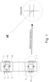
- Fig. 1 shows a cross section of part of a ball bearing. You can see the outer ring 1, the inner ring 2 and a ball 3 of the ball bearing. Furthermore, the seals 4 attached to the sides can be seen. Also shown is the lubricant 14 present between the outer ring 1 and the ball 3 and the lubricant 14 present between the inner ring 2 and the ball 3. For clarity, undesirable interference currents 15 are also shown, which flow from the inner ring 2 via the lubricant to the ball 3 and flow from the ball 3 via the lubricant 14 to the outer ring 1. Such unwanted currents 15 are often referred to as bearing currents. Fig. 1 also illustrates the electrical equivalent of the ball bearing components highlighted in the dashed circle.
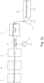
- the Fig. 2 shows an experimental setup that was used to demonstrate the effectiveness of the invention.
- the Fig. 2a shows schematically the structure of a bearing test bench as an embodiment.
- the mechanical component 5 is a ball bearing that supports a rotor 7 driven by a motor shaft 6 in a stator 12.
- the motor shaft 6 is connected to a motor 8, which is powered by a power source 9 and a converter 10 connected downstream of the power source 9.
- a voltage signal is coupled into the motor shaft 6 by means of a signal generator 17.
- a voltmeter is used as the measuring device 11, which is coupled to the stator 12 and determines the voltage difference between the stator 12 and, for example, earth (ground). The determined voltage is recorded in an evaluation unit 13 in the time domain.
- the evaluation unit 13 calculates a histogram from the time-related voltage curves (cf. Fig. 5 , Fig. 6 ). The determination of the bearing condition results from the distribution of the histogram.
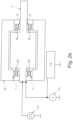
- the Fig. 2b it can be seen that two ball bearings are used as mechanical components 5 to support the rotor. The state of the ball bearings can be determined by determining the voltage difference between the stator 12 and earth (ground) as an electrical variable. As in Fig. 2a the determined voltage is recorded by an evaluation unit 13 in the time domain. The evaluation unit 13 calculates a histogram from the time-related voltage curves (cf. Fig. 5 , Fig. 6 ). The determination of the bearing condition results from the distribution of the histogram.
- Two operating states were considered, namely the standstill of the ball bearings as a reference and a short period of time in the braking phase (reduction in speed) at 10% of the maximum speed of the motor/bearing.
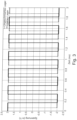
- the Y-axis represents the voltage
- the X-axis represents the time
- the Y-axis represents the frequency of the voltage ranges
- the X-axis represents the existing voltage ranges.
- the Fig. 3 shows the voltage curves of the reference voltage at the two bearings over time at standstill.
- the phase shift is irrelevant here because the tests were carried out one after the other. However, it can be seen that there is no difference in amplitude between the two bearings when stationary. This is also to be expected when the bearing is at a standstill, as no significant lubricant film forms in the bearing when the bearing is at a standstill.
- the DC voltage difference between the reference voltages was 8.9mV at standstill.
- the Fig. 4 shows the voltage curves of the two bearings over time during the braking phase at 10% of the maximum speed.
- the voltage curves of the two curves show transient processes that are caused by the rotational movement of the bearings. While the stress curve in the unlubricated bearing is almost symmetrical remains metric, the voltage amplitude of the intact bearing shifts downwards by more than 800mV. The DC voltage difference between the bearings was 932mV in this section of the braking phase.
- the Fig. 5 shows the frequency of the voltage ranges on the two bearings at standstill. It can be seen that all existing voltage ranges are concentrated at the maximum amplitudes of the reference voltage and there are no significant voltage spreads in other areas.
- the Fig. 6 shows the histogram of the frequencies of the voltage ranges on the two bearings in the operating state with 10% of the maximum speed (a short section in the braking phase).
- the ones in the Fig. 6 The vertical dashed lines shown represent the amplitude of the reference voltages.
- the vertical solid or dotted lines represent the center of the stress distributions for both bearings.
- the black and white arrows show the displacement magnitude and direction of displacement from the amplitude of the reference voltage.
- the investigations show that the condition of a mechanical component can be determined by looking at the voltage.
Landscapes
- Physics & Mathematics (AREA)
- General Physics & Mathematics (AREA)
- Engineering & Computer Science (AREA)
- Algebra (AREA)
- Artificial Intelligence (AREA)
- Evolutionary Computation (AREA)
- Mathematical Analysis (AREA)
- Mathematical Optimization (AREA)
- Mathematical Physics (AREA)
- Probability & Statistics with Applications (AREA)
- Pure & Applied Mathematics (AREA)
- Automation & Control Theory (AREA)
- Testing Of Devices, Machine Parts, Or Other Structures Thereof (AREA)
- Rolling Contact Bearings (AREA)
Description
- Die Erfindung betrifft eine Vorrichtung zur Bestimmung des Zustands eines mechanischen Bauteils, bei dem im Einsatz des Bauteils zumindest ein Teil des Bauteils relativ zu einem anderen Bauteil bewegt wird. Ferner betrifft die Erfindung ein System und ein Verfahren zur Bestimmung des Zustands eines mechanischen Bauteils.
- Sowohl bei der Herstellung von mechanischen Bauteilen, bei denen im Einsatz des Bauteils zumindest ein Teil des Bauteils relativ zu einem anderen Bauteil bewegt wird, wie insbesondere Antrieben oder Lagern, als auch beim Betrieb mechanischer Bauteile besteht ein Interesse an Informationen über den Zustand des mechanischen Bauteils. Bei der Herstellung eines mechanischen Bauteils besteht insbesondere ein Interesse daran, festzustellen, ob das mechanische Bauteil den bei seiner Auslegung und Konstruktion festgelegten Qualitätsstandards entspricht und insbesondere alle bei der Konstruktion vorgesehenen Bauteile enthält, diese Bauteile die gewünschte Form haben, diese Bauteile in der gewünschten Qualität vorliegen (beispielsweise rißfrei und ohne Lunker) und ob Teile des mechanischen Bauteils die bei der Auslegung und Konstruktion des Bauteils festgelegten Abstände einzelner Bauteile zueinander einhalten, insbesondere festgelegte Toleranzen. Ferner interessiert bei der Herstellung neuer mechanischer Bauteile, ob das mechanische Bauteil die bei seiner Auslegung und Konstruktion festgelegte Schmierung, insbesondere auch hinsichtlich des Ortes, an dem sich die Schmierung befinden soll, sowie hinsichtlich der Qualität des eingesetzten Schmiermittels, aber auch hinsichtlich der Menge des vorzusehenden Schmiermittels hat.
- Bei dem Betrieb eines mechanischen Bauteils, bei dem im Einsatz des Bauteils zumindest ein Teil des Bauteils relativ zu einem anderen Bauteil bewegt wird, besteht insbesondere ein Interesse daran, festzustellen, ob das mechanische Bauteil den bei seiner Auslegung und Konstruktion festgelegten Qualitätsstandards weiterhin entspricht, bzw. der bei der Auslegung und Konstruktion berücksichtigte Alterungsprozess in dem Maße eintritt, wie geplant, und insbesondere alle bei der Konstruktion vorgesehenen Bauteile weiterhin vorhanden sind, diese Bauteile weiterhin die gewünschte, bzw. dem erwarteten Alterungsprozess entsprechende Form haben, diese Bauteile weiterhin in der gewünschten Qualität vorliegen (beispielsweise rißfrei und ohne Lunker) und ob Teile des mechanischen Bauteils die bei der Auslegung und Konstruktion des Bauteils festgelegten Abstände einzelner Bauteile zueinander einhalten, insbesondere festgelegte Toleranzen. Ferner interessiert bei dem Betrieb mechanischer Bau-teile, ob das mechanische Bauteil die bei seiner Auslegung und Konstruktion festgelegte Schmierung, insbesondere auch hinsichtlich des Ortes, an dem sich die Schmierung befinden soll, sowie hinsichtlich der Qualität des eingesetzten Schmiermittels, aber auch hinsichtlich der Menge des vorzusehenden Schmiermittels hat.
- Im Stand der Technik ist es bekannt, den Zustand eines mechanischen Bauteils, bei dem im Einsatz des Bauteils zumindest ein Teil des Bauteils relativ zu einem anderen Bauteil bewegt wird, mit mechanischen Messmethoden zu ermitteln. So werden Messungen und Abstände zueinander häufig mittels entsprechender Messmethoden, aber vor allem Schieblehren untersucht. Hinsichtlich der Schmierung ist es häufig vorgesehen, Proben zu nehmen und diese Proben hinsichtlich der Qualität des Schmiermittels, insbesondere auch im Hinblick auf eine mögliche Alterung, zu prüfen. Ferner ist es im Betrieb von mechanischen Bauteilen bekannt, mit Wartungsplänen zu arbeiten, die häufig auf Betriebsstunden oder beispielsweise gefahrenen Kilometern (bei einem Kraftfahrzeug) basieren.
- Aus
WO 2015/043619 A1 ist eine Vorrichtung und ein Verfahren nach dem Oberbegriff der Ansprüche 1 bzw. 4 bekannt. -
WO 2006/134068 A1 offenbart eine Anordnung und ein Verfahren zur Lagerstromüberwachung eines Elektromotors. -
US 5 936 410 A offenbart ein hydrodynamisches Lager mit Mitteln zur Überwachung der Kapazität zwischen dem Rotor und dem Stator des hydrodynamischen Lagers. -
WO 2008/000285 A1 offenbart ein Verfahren zum Anzeiegn von Ermüdungsschäden an einem metallischen Gegenstand. - Vor diesem Hintergrund lag der Erfindung die Aufgabe zugrunde, eine Vorrichtung sowie ein System und ein Verfahren zur Bestimmung des Zustands eines mechanischen Bauteils, bei dem im Einsatz des Bauteils zumindest ein Teil des Bauteils relativ zu einem anderen Bauteil bewegt wird, vorzuschlagen, die sich insbesondere einfach durchführen lässt.
- Diese Aufgabe wird durch die Vorrichtung gemäß Anspruch 1, das System gemäß Anspruch 3 und das Verfahren gemäß Anspruch 4 gelöst. Vorteilhafte Ausführungsformen sind in Anspruch 2 und der hier nachfolgenden Beschreibung wiedergegeben.
- Die Erfindung geht von dem Grundgedanken aus, den Zustand eines mechanischen Bauteils, bei denen im Einsatz des Bauteils zumindest ein Teil des Bauteils relativ zu einem anderen Bauteil bewegt wird, nicht mit mechanischen Messmethoden zu ermitteln, sondern durch die Bestimmung einer elektrischen Größe oder durch die Bestimmung einer Änderung einer elektrischen Größe, die erfindungsgemäß eine elektrische Spannung ist. Die Erfindung hat nämlich erkannt, dass eine Spannung, die an dem mechanischen Bauteil bestimmt wird, eine Aussage über den Zustand des mechanischen Bauteils geben kann.
- Es wurde erkannt, dass bereits der absolute Wert der Spannung eine Aussage über den Zustand des mechanischen Bauteils geben kann. Es wurde aber auch erkannt, dass das Beobachten der Änderung der Spannung über einen Zeitabschnitt eine Aussage über den Zustand eines mechanischen Bauteils zulässt.
- Ebenso kann die Betrachtung der Änderungsrate eine Aussage über den Zustand des mechanischen Bauteils liefern, also die Erkenntnis darüber, dass sich beispielsweise die Impedanz in einem ersten Beobachtungszeitraum mit einer ersten Rate und in einem zweiten Beobachtungszeitraum mit einer zweiten Rate ändert.
- Die Betrachtung wird über eine Motorwelle des Bauteils eingeleitetes Spannungssignal erfolgen, da das elektrische, messbare Signalübertragungsverhalten der Spannung vom Zustand des bewegbaren Bauteils abhängt. Es ist auch möglich, dass zusätzlich ein parasitäres Spannungssignal betrachtet wird.
- Mit den vorgestellten Verfahren kann man eine detaillierte Eigenschaftsprüfung der montierten, neuen Lager durchführen und somit auch die Maßhaltigkeit des Gesamtsystems überwachen.
- Mit der Erfindung kann insbesondere als Zustand des mechanischen Bauteils, bei dem im Einsatz des Bauteils zumindest ein Teil des Bauteils relativ zu einem anderen Bauteil bewegt wird, festgestellt werden, ob das Bauteil geschmiert ist und welcher Grad der Schmierung (insbesondere die Änderung der Dicke des Schmierfilms) vorliegt und welche Güte (insbesondere welcher Alterungszustand) das Schmiermittel hat. Die Erfindung bietet beispielsweise die Möglichkeit der frühzeitigen Bewertung der Schmierstoffqualität in einem Lager oder in einem Antriebsstrang. Dies ist wichtig, da sehr viele Lagerdefekte auf Grund einer ungenügenden Schmierung erfolgen. Die Erfindung lässt eine Analyse auch von sehr langsam drehenden Lagern zu, die beispielsweise mit einer Schwingungsanalyse kaum analysierbar sind. Die Erfindung erlaubt die frühzeitige Zustandserkennung des Lagers oder des Getriebes oder des Antriebsstrangs bzw. mechanische Beschädigungen dieser. Mit der Erfindung kann als Zustand des bewegbaren mechanischen Bauteils festgestellt werden, ob mechanische Schäden am oder im Bauteil vorliegen, also Abweichungen von der bei der Auslegung und Konstruktion des mechanischen Bauteils festgelegten Form der Teile des Bauteils bestehen. Ebenso kann die Maßhaltigkeit von Teilen des mechanischen Bauteils geprüft werden. Ebenso sind Abweichungen in Werkstoffqualitäten detektierbar, nämlich solche, die einen Einfluss auf die elektrische Leitfähigkeit haben.
- Als zu bestimmende elektrische Größe bzw. als elektrische Größe, deren Änderung erfindungsgemäß bestimmt wird, wird die elektrische Spannung, die am Bauteil anliegt bestimmt.
- Die erfindungsgemäße Vorrichtung zur Bestimmung des Zustands eines mechanischen Bauteils, das ein Lager ist, weist ein Messgerät auf, das als Voltmeter ausgestaltet ist. Die Auswertung der Messsignale erfolgt üblicherweise mit einem Mikroprozessor.
- Die erfindungsgemäße Vorrichtung weist eine Auswerteeinheit auf, die auf Grundlage eines von dem Messgerät erzeugten Messergebnisses eine Zustandsinformation über den Zustand des mechanischen Bauteils, bei dem im Einsatz des Bauteils zumindest ein Teil des Bauteils relativ zu einem anderen Bauteil bewegt wird, ausgibt. Insbesondere bevorzugt besteht zwischen dem Messgerät und der Auswerteeinheit eine Signalleitung, entlang der insbesondere bevorzugt ein elektrisches oder ein optisches Signal zwischen dem Messgerät und der Auswerteeinheit ausgetauscht werden kann. Dabei ist insbesondere bevorzugt eine Größe des Signals, beispielsweise dessen Stärke oder dessen zeitlicher Verlauf abhängig von einer charakteristischen Größe der von dem Messgerät bestimmten Spannung oder der Änderung der Spannung.
- Die Ausgabe der Zustandsinformation kann sehr vereinfacht sein, so kann beispielsweise vorgesehen sein, dass die Auswerteeinheit beim Erreichen eines bestimmten, nicht gewünschten Zustandes eine Zustandsinformation in Form eines optischen Reizes (beispielsweise geht ein rotes Licht an) oder eines Tons abgibt, während das Fehlen eines optischen Reizes oder eines Tons die Information darüber ist, dass der Zustand des mechanischen Bauteils, bei dem im Einsatz des Bauteils zumindest ein Teil des Bauteils relativ zu einem anderen Bauteil bewegt wird, den unerwünschten Zustand noch nicht erreicht hat. Auch ist es denkbar, dass die Zustandsinformation graduell, beispielsweise nach einem Ampelsystem, abgeben wird. Auch ist es denkbar, dass mittels der Erfindung konkrete Aussagen über den Zustand des mechanischen Bauteils, bei dem im Einsatz des Bauteils zumindest ein Teil des Bauteils relativ zu einem anderen Bauteil bewegt wird, getroffen werden können, beispielsweise nach wieviel weiteren Betriebsstunden des mechanischen Bauteils, bei dem im Einsatz des Bauteils zumindest ein Teil des Bauteils relativ zu einem anderen Bauteil bewegt wird, mit dem Ausfallen eines bestimmten Bauteils zu rechnen ist.
- In einer bevorzugten Ausführungsform ist in der Auswerteeinheit eine Tabelle abgelegt, in der eine jeweilige Zustandsinformation über den Zustand des mechanischen Bauteils einem jeweiligen Messergebnis des Messgeräts zugeordnet ist. In dieser Ausführungsform arbeitet die Auswerteeinheit somit mit einer "look up-Table". In dieser Tabelle können Erfahrungswerte eingetragen werden, die sich mittels einfacher Prüfstanduntersuchungen ermitteln lassen.
- Die erfindungsgemäße Vorrichtung weist eine Spannungsquelle als Signalgenerator auf, mit der eine Spannung an der Motorwelle über ein mechanisches Bauteil angelegt werden kann. Für das Bestimmen bestimmter der Spannung bzw. für das Bestimmen bestimmter Änderungen der Spannung ist es notwendig, eine Spannung an der Motorwelle über das mechanische Bauteil anzulegen. Indem die Vorrichtung mit einer Spannungsquelle ausgestattet wird, wird die erfindungsgemäße Vorrichtung autark.
- Die erfindungsgemäße Vorrichtung ist dazu ausgebildet, ein Eingangssignal an der Motorwelle in das mechanische Bauteil einzubringen.
- Das as Messgerät kann so ausgeführt sein, dass es eine über dem mechanischen Bauteil anliegende Spannung über eine vorbestimmte Messperiode messen kann. Insbesondere bevorzugt ist in dieser Ausführungsform vorgesehen, dass eine Auswerteeinheit vorgesehen ist, die ein Modul zur Auswertung des Verlaufs der gemessenen Spannung mit einem multivariaten statistischen Verfahren während der Messperiode aufweist, wobei aus der Auswertung eine Zustandsinformation über den Zustand des bewegbaren mechanischen Bauteils ausgegeben wird.
- Das beobachtete mechanische Bauteil ist erfindungsgemäß ein Lager.
- Das erfindungsgemäße System weist das mechanische Bauteil und eine erfindungsgemäße Vorrichtung auf. Das erfindungsgemäße System beschreibt zum einen den Zustand, wenn, beispielsweise für eine individuelle Messung des Zustands des mechanischen Bauteils, die erfindungsgemäße Vorrichtung in der Weise mit dem mechanischen Bauteil verbunden ist, dass das Messgerät der erfindungsgemäßen Vorrichtung die Spannung oder die Änderung der Spannung an dem mechanischen Bauteil bestimmen kann. Das schließt nicht aus, dass das erfindungsgemäße System ein Trennen der erfindungsgemäßen Vorrichtung von dem mechanischen Bauteil erlaubt und das erfindungsgemäße System somit nur kurzzeitig (während der Messung) besteht. Gleichzeitig umfasst der erfindungsgemäße Systemanspruch integrierte Einheiten aus dem mechanischen Bauteil und der erfindungsgemäßen Vorrichtung. So lässt sich die Erfindung beispielsweise sehr gut für Onboard-Diagnosesysteme einsetzen, beispielsweise in Fahrzeugen, insbesondere in Schienenfahrzeugen oder Straßenfahrzeugen, insbesondere Kraftfahrzeugen oder beispielsweise an Produktionsanlagen, wie beispielsweise Walzwerken.
- Das erfindungsgemäße Verfahren sieht vor, dass mit einem Messgerät eine Spannung oder die Änderung einer Spannung an dem mechanischen Bauteil bestimmt wird.
- Es wird mit einer Spannungsquelle eine Spannung an die Motorwelle angelegt und mit einem Messgerät, das ein Voltmeter ist, welches ausgestaltet ist, an der Motorwelle anzukoppeln, die Spannungsdifferenz zwischen Stator und Erde ermittelt. Es kann mit der Auswerteeinheit der Verlauf der gemessenen Spannung während der Messperiode mit einem multivariaten statistischen Verfahren ausgewertet werden, wobei die Auswerteeinheit aus der Auswertung eine Zustandsinformation über den Zustand des bewegbaren mechanischen Bauteils ausgibt. Dieser Ausführungsform liegt die Erkenntnis zugrunde, dass nicht nur aus der Höhe einer zu einem bestimmten Zeitpunkt gemessenen Spannung eine Zustandsinformation über den Zustand des bewegbaren mechanischen Bauteils gewonnen werden kann, sondern dass beispielsweise auch aus einer Auswertung des Spannungsverlaufs mit einem multivariaten statistischen Verfahren über eine vorbestimmte Messperiode Zustandsinformationen über den Zustand des bewegbaren mechanischen Bauteils gewonnen werden können.
- In einer Ausführungsform enthält die statistische Auswertung die Bestimmung der Häufigkeitsverteilung einzelner Spannungen über die vorbestimmte Messperiode. Beispielsweise kann als Ergebnis der statistischen Auswertung ein Histogramm erzeugt werden, das aufzeigt, welche Spannung innerhalb der vorbestimmten Messperiode wie häufig vorlag. Zur Vereinfachung und aus Übersichtlichkeitsgründen kann das Histogramm in den in ihm dargestellten Balken Spannungen zu Span-nungsbereichen zusammenfassen; der Balken des Histogramms zeigt dann an, wie häufig eine Spannung aus diesem Spannungsbereich vorlag.
- In einer Ausführungsform vergleicht die Auswerteeinheit das Ergebnis der Auswertung mit einem multivariaten statistischen Verfahren des Spannungsverlaufs über eine vorbestimmte Messperiode mit dem Ergebnis der Auswertung mit einem multivariaten statistischen Verfahren des Spannungsverlaufs über eine gleichlange, jedoch früheren Messperiode. Dieser Ausführungsform liegt die Erkenntnis zugrunde, dass sich der Spannungsverlauf über eine Messperiode mit vorbestimmter Länge in Abhängigkeit des Zustands des Bauteils ändert. Deshalb wird es möglich, anhand des Vergleichs des Ergebnisses der Auswertung mit einem multivariaten statistischen Verfahren des Spannungsverlaufs über eine erste Messperiode mit dem Ergebnis der Auswertung mit einem multivariaten statistischen Verfahren des Spannungsverlaufs über eine zweite Messperiode, die gleichlang wie die erste Messperiode ist, eine Zustandsänderung des Bauteils festzustellen.
- Das multivariate statistische Verfahren ist insbesondere ein statistisches Verfahren.
- In einer Ausführungsform bewegt sich während der Durchführung des erfindungsgemäßen Verfahrens ein Teil des zu untersuchenden mechanischen Bauteils relativ zu einem anderen Teil des zu untersuchenden mechanischen Bauteils. Es ist jedoch auch denkbar, dass das erfindungsgemäße Verfahren erfolgreich an einem ruhenden Bauteil durchgeführt werden kann.
- In einer Ausführungsform ist das Eingangssignal konstant. Es sind jedoch auch Ausführungsformen denkbar, bei denen das Eingangssignal zeitlich variiert, insbesondere eine Sinusform oder eine Pulsform aufweist. In einer bevorzugten Ausführungsform ist das Eingangssignal ein Puls, insbesondere ein Delta-Puls zur Bestimmung der elektrischen Eigenschaften des Bauteils. Das Eingangssignal kann pulsförmige Spannungsfunktionen, wie zum Beispiel ein Rechteckimpuls, ein Dreieckimpulse oder ein Sägezahnimpulse sein. Gute Ergebnisse lassen sich mit einer pulsförmigen Spannungsfunktion mit zumindest einer steilen Signalflanke, vorzugsweise mit einer steilen Eingangsflanke und einer steilen Ausgangsflanke erzielen. Die Grundfrequenz des Signals kann ebenfalls zum Erzielen guter Ergebnisse genutzt werden. Je nach Bewegungsstatus des zu untersuchenden Bauteils ermöglichen diese zwei Parameter durch ihre Abweichungen zum Referenzsignal, nützliche Informationen zu bekommen und dadurch den Zustand des mechanischen Bauteils zu bestimmen.
- In einer Ausführungsform erfolgt die Bestimmung der mechanischen Eigenschaften des Bauteils aus der Ermittlung einer elektrischen Größe im Wege der Durchführung einer Referenzmessung, nach der dann die eigentliche Messung erfolgt.
- Nachfolgend wird die Erfindung anhand von lediglich Ausführungsformen darstellenden Zeichnungen näher erläutert.
- Darin zeigen:
- Fig. 1
- einen schematischen Querschnitt durch einen Teil eines Kugellagers,
- Fig. 2a
- eine schematische Ansicht eines Versuchsaufbaus mit einem mechanischen Bauteil in Form eines Kugellagers und einem Messgerät,
- Fig. 2b
- eine schematische Ansicht eines Teils des in
Fig. 2a gezeigten Versuchsaufbaus, nämlich des beobachteten Lagers mit weiteren Details, - Fig. 3
- eine Grafik, die eine Referenzspannung an einem intakten und einem ungeschmierten Lager im Stillstand zeigt,
- Fig. 4
- eine Grafik, die die Spannungsverläufe an dem intakten und an dem ungeschmierten Lager im Betriebszustand mit 10% der Nennfrequenz für einen Abschnitt von zwei Millisekunden in der Bremsphase zeigt,
- Fig. 5
- ein Histogramm zum Vergleich der Referenzspannung beim intakten und beim ungeschmierten Lager im Stillstand und
- Fig. 6
- ein Histogramm zum Vergleich der Häufigkeit von Spannungsbereichen bei dem intakten und bei dem ungeschmierten Lager in der Bremsphase mit 10% der Nennfrequenz.
-
Fig. 1 zeigt einen Querschnitt eines Teils eines Kugellagers. Zu erkennen sind der Außenring 1, der Innenring 2 sowie eine Kugel 3 des Kugellagers. Ferner sind die seitlich angebrachten Dichtungen 4 zu erkennen. Ebenso eingezeichnet ist der zwischen dem Außenring 1 und der Kugel 3 vorhandene Schmierstoff 14 sowie der zwischen dem Innenring 2 und der Kugel 3 vorhandene Schmierstoff 14. Zur Verdeutlichung sind zudem unerwünschte Störströme 15 eingezeichnet, die von dem Innenring 2 über den Schmierstoff zur Kugel 3 und von der Kugel 3 über den Schmierstoff 14 zum Außenring 1 fließen. Derartige unerwünschte Ströme 15 werden häufig als Lagerströme bezeichnet.Fig. 1 verdeutlicht auch das elektrische Äquivalent der in dem gestrichelten Kreis hervorgehobenen Bauteile des Kugellagers. - Die
Fig. 2 zeigt einen Versuchsaufbau, der eingesetzt wurde, um die Wirksamkeit der Erfindung zu demonstrieren. DieFig. 2a zeigt schematisch den Aufbau eines Lagerprüfstandes als Ausführungsform. Bei dem mechanischen Bauteil 5 handelt es sich um Kugellager, die einen von einer Motorwelle 6 angetriebenen Rotor 7 in einem Stator 12 lagern. Die Motorwelle 6 ist mit einem Motor 8 verbunden, der mittels einer Stromquelle 9 und einem der Stromquelle 9 nachgeschalteten Umrichter 10 versorgt wird. An der Motorwelle 6 wird mittels eines Signalgenerators 17 ein Spannungssignal eingekoppelt. Als Messgerät 11 wird ein Voltmeter verwendet, welches an dem Stator 12 angekoppelt ist und die Spannungsdifferenz zwischen dem Stator 12 und beispielsweise Erde (Masse) ermittelt. Die ermittelte Spannung wird in einer Auswerteeinheit 13 im Zeitbereich erfasst. Die Auswerteeinheit 13 berechnet von den zeitbezogenen Spannungsverläufen ein Histogramm (vgl.Fig. 5 ,Fig. 6 ). Die Bestimmung des Lagerzustands ergibt sich aus der Verteilung des Histogramms. DerFig. 2b ist zu entnehmen, dass zwei Kugellager als mechanische Bauteile 5 verwendet werden, um den Rotor zu lagern. Von den Kugellagern kann der Zustand bestimmt werden, indem als elektrische Größe die zwischen dem Stator 12 und Erde (Masse) vorliegende Spannungsdifferenz ermittelt wird. Wie inFig. 2a wird die ermittelte Spannung durch eine Auswerteeinheit 13 im Zeitbereich erfasst. Die Auswerteeinheit 13 berechnet von den zeitbezogenen Spannungsverläufen ein Histogramm (vgl.Fig. 5 ,Fig. 6 ). Die Bestimmung des Lagerzustands ergibt sich aus der Verteilung des Histogramms. - Zur Lagerschadenfrüherkennung wurden zwei Lager des gleichen Typs als Probe verwendet (ein intaktes Lager und ein defektes, d.h. ungeschmiertes Lager). Ein Rechtecksignal mit einer Grundfrequenz von 3 kHz und einer Amplitude von 2V (2V, -2V) wurde als Referenzsignal benutzt.
- Es wurden zwei Betriebszustände betrachtet, nämlich der Stillstand der Kugellager als Referenz sowie ein kurzen Zeitabschnitt in der Bremsphase (Reduktion der Drehzahl) bei 10% der maximalen Drehzahl des Motors/Lagers.
- In
Fig. 3 und4 repräsentiert die Y-Achse die Spannung die X-Achse die Zeit. In denFig. 5 und6 repräsentiert die Y-Achse die Häufigkeit der Spannungsbereiche und die X-Achse die vorhandenen Spannungsbereiche. - Die
Fig. 3 zeigt die Spannungsverläufe der Referenzspannung an den beiden Lagern über Zeit im Stillstand. Die Phasenverschiebung ist hier ohne Relevanz, da die Versuche nacheinander durchgeführt wurden. Zu erkennen ist allerdings, dass kein Amplitudenunterschied zwischen den beiden Lagern im Stillstand festzustellen ist. Dies ist im Stillstand auch so zu erwarten, da sich im Stillstand kein signifikanter Schmierfilm im Lager einstellt. Gleichspannungsunterschied zwischen den Referenzspannungen lag bei 8,9mV im Stillstand. - Die
Fig. 4 zeigt die Spannungsverläufe der beiden Lager über der Zeit während der Bremsphase mit 10% der maximalen Drehzahl. Die Spannungsverläufe der beiden Kurven zeigen transiente Vorgänge, die durch die Drehbewegung der Lager verursacht werden. Während der Spannungsverlauf bei dem ungeschmierten Lager nahezu sym metrisch bleibt, verschiebt sich die Spannungsamplitude des intakten Lagers um mehr als 800mV nach unten. Der Gleichspannungsunterschied zwischen den Lagern lag bei 932mV in diesem Abschnitt der Bremsphase. - Die
Fig. 5 zeigt die Häufigkeit der Spannungsbereiche an den beiden Lagern im Stillstand. Es ist festzustellen, dass alle vorhandenen Spannungsbereiche bei den maximalen Amplituden der Referenzspannung konzentriert sind und keine signifikanten Spannungsstreuungen in anderen Bereichen vorhanden sind. - Die
Fig. 6 zeigt das Histogramm der Häufigkeiten der Spannungsbereiche an den beiden Lagern im Betriebszustand mit 10% der maximalen Drehzahl (einen kurzen Abschnitt in der Bremsphase). Bei dem ungeschmierten Lager kann eine Spannungsverschiebung, wie auch inFig. 5 zu erkennen, festgestellt werden. Ferner kann ein klarer Unterschied zwischen den beiden Kurven (zwischen dem intakten Lager und zwischen dem ungeschmierten Lager) erkannt werden. Die Art der Verteilung der Spannungshäufigkeiten ermöglicht eine Zuordnung des Lagerzustandes. - Die in der
Fig. 6 eingezeichneten vertikalen gestrichelten Linien repräsentieren die Amplitude der Referenzspannungen. Die vertikalen durchgezogenen bzw. gepunktet gestrichelten Linien repräsentieren die Mitte der Spannungsverteilungen für beide Lager. Die schwarzen und weißen Pfeile zeigen die Verschiebungsstärke und die Verschiebungsrichtung von der Amplitude der Referenzspannung. - Die Untersuchungen zeigen somit, dass durch das Betrachten der Spannung der Zustand eines mechanischen Bauteils ermittelt werden kann.
Claims (4)
- Vorrichtung zur Bestimmung des Zustandes eines mechanischen Bauteils (5), das ein Lager ist, welches einen von einer Motorwelle (6) angetriebenen Rotor (7) in einem Stator (12) lagert, bei dem im Einsatz des Bauteils zumindest ein Teil des Bauteils relativ zu einem anderen Bauteil bewegt wird, wobei ein Messgerät (11), das eine elektrische Größe des mechanischen Bauteils (5) oder die Änderung einer elektrischen Größe bestimmen kann, und eine Auswerteeinheit (13), die auf Grundlage eines von dem Messgerät (11) erzeugten Messergebnisses eine Zustandsinformation über den Zustand des bewegbaren mechanischen Bauteils (5) ausgibt, vorhanden sind, dadurch gekennzeichnet, dass ein Signalgenerator (17) vorhanden ist, der ausgestaltet ist, ein Spannungssignal an der Motorwelle (6) einzukoppeln, und das Messgerät (11) ein Voltmeter ist, welches ausgestaltet ist, an dem Stator (12) anzukoppeln und die Spannungsdifferenz zwischen dem Stator (12) und Erde zu ermitteln.
- Vorrichtung nach Anspruch 1, gekennzeichnet durch eine in der Auswerteeinheit (13) abgelegte Tabelle, in der eine jeweilige Zustandsinformation über den Zustand des bewegbaren mechanischen Bauteils (5) einem jeweiligen Messergebnis des Messgeräts (11) zugeordnet ist.
- System aus dem mechanischen Bauteil (5) und einer Vorrichtung nach einem der Ansprüche 1 bis 2.
- Verfahren zur Bestimmung des Zustandes eines mechanischen Bauteils (5), das ein Lager ist, welches einen von einer Motorwelle (6) angetriebenen Rotor (7) in einem Stator (12) lagert, wobei mit einem Messgerät (11) eine elektrische Größe oder die Änderung einer elektrischen Größe an dem mechanischen Bauteil (5) bestimmt wird, wobei eine Auswerteeinheit (13) auf Grundlage eines von dem Messgerät (11) erzeugten Messergebnisses eine Zustandsinformation über den Zustand des bewegbaren mechanischen Bauteils (5) ausgibt, dadurch gekennzeichnet, dass ein mittels eines Signalgenerators (17) erzeugtes Spannungssignal an der Motorwelle (6) eingekoppelt wird, und das Messgerät (11) ein Voltmeter ist, welches an dem Stator (12) angekoppelt wird und die Spannungsdifferenz zwischen dem Stator (12) und Erde ermittelt.
Priority Applications (1)
| Application Number | Priority Date | Filing Date | Title |
|---|---|---|---|
| EP23199034.2A EP4283317B1 (de) | 2017-07-24 | 2018-07-18 | Vorrichtung, system und verfahren zur bestimmung des zustands eines mechanischen bauteils |
Applications Claiming Priority (2)
| Application Number | Priority Date | Filing Date | Title |
|---|---|---|---|
| DE102017212666.3A DE102017212666B4 (de) | 2017-07-24 | 2017-07-24 | Verfahren und Vorrichtung zur Bestimmung des Zustands eines mechanischen Bauteils |
| PCT/EP2018/069562 WO2019020473A1 (de) | 2017-07-24 | 2018-07-18 | Vorrichtung zur bestimmung des zustands eines mechanischen bauteils, verwendung eines messgeräts, system, verfahren zur bestimmung des zustands eines mechanischen bauteils |
Related Child Applications (2)
| Application Number | Title | Priority Date | Filing Date |
|---|---|---|---|
| EP23199034.2A Division EP4283317B1 (de) | 2017-07-24 | 2018-07-18 | Vorrichtung, system und verfahren zur bestimmung des zustands eines mechanischen bauteils |
| EP23199034.2A Division-Into EP4283317B1 (de) | 2017-07-24 | 2018-07-18 | Vorrichtung, system und verfahren zur bestimmung des zustands eines mechanischen bauteils |
Publications (2)
| Publication Number | Publication Date |
|---|---|
| EP3658882A1 EP3658882A1 (de) | 2020-06-03 |
| EP3658882B1 true EP3658882B1 (de) | 2024-01-03 |
Family
ID=62981215
Family Applications (2)
| Application Number | Title | Priority Date | Filing Date |
|---|---|---|---|
| EP18743471.7A Active EP3658882B1 (de) | 2017-07-24 | 2018-07-18 | Vorrichtung, system und verfahren zur bestimmung des zustands eines mechanischen bauteils |
| EP23199034.2A Active EP4283317B1 (de) | 2017-07-24 | 2018-07-18 | Vorrichtung, system und verfahren zur bestimmung des zustands eines mechanischen bauteils |
Family Applications After (1)
| Application Number | Title | Priority Date | Filing Date |
|---|---|---|---|
| EP23199034.2A Active EP4283317B1 (de) | 2017-07-24 | 2018-07-18 | Vorrichtung, system und verfahren zur bestimmung des zustands eines mechanischen bauteils |
Country Status (7)
| Country | Link |
|---|---|
| US (1) | US11371910B2 (de) |
| EP (2) | EP3658882B1 (de) |
| JP (1) | JP7791648B2 (de) |
| CN (1) | CN110959108B (de) |
| DE (1) | DE102017212666B4 (de) |
| ES (1) | ES2970613T3 (de) |
| WO (1) | WO2019020473A1 (de) |
Families Citing this family (3)
| Publication number | Priority date | Publication date | Assignee | Title |
|---|---|---|---|---|
| DE102019117879A1 (de) * | 2019-07-02 | 2021-01-07 | Dr. E. Horn GmbH & Co. KG | Verfahren und Sensor zur Überwachung eines Zustandes eines Ensembles aus zumindest einem ersten Bauteil in einem zweiten Bauteil |
| CN117836600B (zh) * | 2021-08-12 | 2025-06-20 | 三菱电机楼宇解决方案株式会社 | 轴承的检查方法 |
| DE102021125852A1 (de) | 2021-10-05 | 2023-04-06 | HCP Sense GmbH | Verfahren zum Bestimmen einer Ausdehnung eines Schadens in einem Lager |
Citations (1)
| Publication number | Priority date | Publication date | Assignee | Title |
|---|---|---|---|---|
| US20150355075A1 (en) * | 2014-06-05 | 2015-12-10 | Aktiebolaget Skf | Rolling bearing and sensor assembly including the same |
Family Cites Families (29)
| Publication number | Priority date | Publication date | Assignee | Title |
|---|---|---|---|---|
| DE825178C (de) | 1950-01-12 | 1951-12-17 | Hugo Kibele | Verfahren zum Anzeigen der Lagerreibung waehrend des Betriebes einer Maschine |
| JPS5741740Y2 (de) | 1977-11-04 | 1982-09-13 | ||
| DE3338420C2 (de) | 1983-10-22 | 1985-11-07 | Schaller-Automation Industrielle Automationstechnik KG, 6653 Blieskastel | Verfahren zur Überwachung von Schmierstellen |
| JPS63105068U (de) | 1986-12-24 | 1988-07-07 | ||
| JPH06100442B2 (ja) * | 1990-02-19 | 1994-12-12 | 株式会社前川製作所 | 密閉式回転機械の回転軸部摩耗検出装置 |
| JPH06510116A (ja) * | 1991-04-17 | 1994-11-10 | ベミス・マニファクチュアリング・カンパニー | データ点解析の方法及び装置 |
| DE19782249T1 (de) * | 1997-01-24 | 1999-12-02 | Seagate Technology | Hydrodynamisches Lager mit einer Einrichtung zur Überwachung der Kapazität zwischen Rotor und Stator |
| JP3988363B2 (ja) | 2000-07-13 | 2007-10-10 | 株式会社ジェイテクト | 動圧軸受の評価方法 |
| JP2002131188A (ja) * | 2000-10-20 | 2002-05-09 | Sankyo Seiki Mfg Co Ltd | モータ軸受監視装置および記憶装置 |
| JP4674395B2 (ja) * | 2000-10-20 | 2011-04-20 | 日本電産株式会社 | 軸受検査方法 |
| CH697582B1 (de) | 2004-03-09 | 2008-12-15 | Schaller Automation | Verfahren und Einrichtung zur Steuerung der Zufuhr von Schmiermittel zur Zylinderlauffläche eines Kolbens eines Hubkolbenmotors. |
| DE102004056996A1 (de) | 2004-11-25 | 2006-06-01 | Siemens Ag | Maschinenanordnung mit einer Maschine, die einen Grundkörper und einen Zusatzkörper aufweist |
| DE102005027670A1 (de) * | 2005-06-15 | 2007-01-11 | Siemens Ag | Anordnung und Verfahren zur Lagerstromüberwachung eines Elektromotors |
| JP4902389B2 (ja) | 2006-03-28 | 2012-03-21 | アルファナテクノロジー株式会社 | 軸受検査方法及びモータの製造方法 |
| US8479587B2 (en) * | 2006-06-28 | 2013-07-09 | Aktiebolaget Skf | Method for indicating fatigue damage of a metal object |
| JP4942496B2 (ja) | 2007-01-26 | 2012-05-30 | Ntn株式会社 | 軸受状態検査装置および軸受状態検査方法 |
| JP2007298527A (ja) | 2007-07-06 | 2007-11-15 | Nsk Ltd | 主軸支持装置 |
| FI20080438A0 (fi) * | 2008-07-15 | 2008-07-15 | Abb Oy | Menetelmä ja laitteisto laakerivirtojen mittaamiseksi sähkökoneessa |
| DE102010002297A1 (de) * | 2010-02-24 | 2011-08-25 | Siemens Aktiengesellschaft, 80333 | Verfahren und Vorrichtung zur Bewertung der Schädigung von Wälzlagern, insbesondere an umrichtergespeisten elektrischen Maschinen |
| DE102010002294A1 (de) | 2010-02-24 | 2011-08-25 | Siemens Aktiengesellschaft, 80333 | System bzw. Verfahren zur Ermittlung eines Lagerzustandes |
| DE102010002296A1 (de) | 2010-02-24 | 2011-08-25 | Siemens Aktiengesellschaft, 80333 | Auswertungsverfahren für Lichtbogenentladungen und zugehöriger Prüfstand |
| JP5143194B2 (ja) | 2010-07-16 | 2013-02-13 | 中国電力株式会社 | ベアリング診断方法 |
| DK2484900T3 (en) | 2011-02-08 | 2017-05-22 | Siemens Ag | Method of lubricating at least one blade pitch bearing of a wind turbine |
| JP6088357B2 (ja) | 2013-05-22 | 2017-03-01 | ファナック株式会社 | モータ軸受の電食の度合いを推定するモータ制御装置、およびその方法 |
| WO2015043619A1 (de) * | 2013-09-24 | 2015-04-02 | Siemens Aktiengesellschaft | Verfahren und vorrichtung zur zustandsüberwachung eines eine elektrische antriebseinheit umfassenden antriebssystems |
| FR3015684B1 (fr) | 2013-12-20 | 2017-03-03 | Skf Aerospace France | Dispositif de mesure de l'usure d'une rotule, rotule integrant ce dispositif et methode de mesure de l'usure d'une telle rotule |
| JP2016024090A (ja) | 2014-07-22 | 2016-02-08 | 日本精工株式会社 | 亀裂検知方法 |
| US9689777B2 (en) * | 2015-05-04 | 2017-06-27 | Deere & Company | Fault detection for bearings |
| JP6330864B2 (ja) * | 2015-08-05 | 2018-05-30 | Jfeスチール株式会社 | モータの監視装置および方法 |
-
2017
- 2017-07-24 DE DE102017212666.3A patent/DE102017212666B4/de active Active
-
2018
- 2018-07-18 US US16/632,798 patent/US11371910B2/en active Active
- 2018-07-18 ES ES18743471T patent/ES2970613T3/es active Active
- 2018-07-18 CN CN201880049678.5A patent/CN110959108B/zh active Active
- 2018-07-18 EP EP18743471.7A patent/EP3658882B1/de active Active
- 2018-07-18 WO PCT/EP2018/069562 patent/WO2019020473A1/de not_active Ceased
- 2018-07-18 EP EP23199034.2A patent/EP4283317B1/de active Active
- 2018-07-18 JP JP2020503279A patent/JP7791648B2/ja active Active
Patent Citations (1)
| Publication number | Priority date | Publication date | Assignee | Title |
|---|---|---|---|---|
| US20150355075A1 (en) * | 2014-06-05 | 2015-12-10 | Aktiebolaget Skf | Rolling bearing and sensor assembly including the same |
Also Published As
| Publication number | Publication date |
|---|---|
| DE102017212666A1 (de) | 2019-01-24 |
| EP4283317C0 (de) | 2024-12-25 |
| JP7791648B2 (ja) | 2025-12-24 |
| EP3658882A1 (de) | 2020-06-03 |
| ES2970613T3 (es) | 2024-05-29 |
| EP4283317B1 (de) | 2024-12-25 |
| CN110959108A (zh) | 2020-04-03 |
| EP4283317A3 (de) | 2023-12-06 |
| WO2019020473A1 (de) | 2019-01-31 |
| CN110959108B (zh) | 2023-01-24 |
| US20210131912A1 (en) | 2021-05-06 |
| DE102017212666B4 (de) | 2023-03-02 |
| JP2020528146A (ja) | 2020-09-17 |
| US11371910B2 (en) | 2022-06-28 |
| EP4283317A2 (de) | 2023-11-29 |
Similar Documents
| Publication | Publication Date | Title |
|---|---|---|
| EP2359106B1 (de) | Verfahren und vorrichtung zur schwingungsanalyse sowie musterdatenbank dafür und verwendung einer musterdatenbank | |
| EP1537390B1 (de) | Verfahren zur erfassung von schwingungen des wellenstranges an einer elektrischen maschine | |
| EP4283317B1 (de) | Vorrichtung, system und verfahren zur bestimmung des zustands eines mechanischen bauteils | |
| DE102016102328A1 (de) | System zur Diagnose von Anomalien, Diagnoseverfahren und -vorrichtung | |
| EP4012426B1 (de) | Verfahren zur korrektur eines zeitabhängigen messsignals einer motor-getriebeeinheit sowie verfahren zur erkennung von verschleiss und/oder einer beschädigung derselben mittels dieses korrekturverfahrens | |
| EP1197415B1 (de) | Verfahren und Vorrichtung zur Erkennung eines schadhaften Wälzlagers eines Schienenfahrzeuges | |
| DE19917541A1 (de) | Verfahren und Vorrichtung zur Fehlerdiagnose | |
| DE102016222660A1 (de) | Verfahren und Vorrichtung zum Erkennen von Veränderungen in einem elektrisch betriebenen Antrieb | |
| DE19702234A1 (de) | Verfahren zur Überwachung und Qualitätsbeurteilung von sich bewegenden und/oder rotierenden Maschinenteilen insbesondere von Maschinenlagern | |
| EP3497401A1 (de) | Verfahren zum vermessen eines schmierspaltes zwischen geschmierten kontaktelementen | |
| DE69823937T2 (de) | Verfahren und Vorrichtung zur Bestimmung von Schwingungen des Rotors einer drehenden Maschine | |
| DE102016212887B4 (de) | Messanordnung für Schmieröl und Messverfahren | |
| DE102009024981A1 (de) | Verfahren zur Ermittlung und Analyse von Schäden an umlaufenden Maschinenelementen | |
| DE102015210911A1 (de) | Verfahren und Vorrichtung zum Erkennen von Veränderungen in einem elektrisch betriebenen Antrieb | |
| EP2378145A2 (de) | Verfahren zur Überwachung einer Linearführung | |
| EP2378146A2 (de) | Verfahren zur Überwachung einer Linearführung | |
| WO2019086160A1 (de) | Verfahren zur zustandsüberwachung einer fertigungsanlage | |
| WO2008019654A1 (de) | Verfahren zur überwachung eines fertigungsverfahrens | |
| EP3966542B1 (de) | Verfahren und prüfstand zur vorhersage von druckschwingungen in einem fahrzeugreifen | |
| WO2023041219A1 (de) | Bewerten von verrundungen von innenbohrungskanten mittels maschinellem lernen unter nutzung von vibrationsdaten oder dergleichen | |
| DE102006010847A1 (de) | Verfahren zum Untersuchen von Lagerschäden | |
| WO2000032458A1 (de) | Verfahren und einrichtung zur ermittlung von zuständen und/oder zustandsänderungen an schienenverkehrseinrichtungen | |
| DE102015205412B4 (de) | Verfahren und Vorrichtung zum Überwachen eines Lagers einer mehrphasigen elektrischen Maschine | |
| EP3891467B1 (de) | Verfahren zum überprüfen einer qualität eines werkstücks sowie recheneinrichtung | |
| DE102012001148A1 (de) | Verfahren zur Herstellung einer vorgegebenen Schraubverbindung |
Legal Events
| Date | Code | Title | Description |
|---|---|---|---|
| STAA | Information on the status of an ep patent application or granted ep patent |
Free format text: STATUS: UNKNOWN |
|
| STAA | Information on the status of an ep patent application or granted ep patent |
Free format text: STATUS: THE INTERNATIONAL PUBLICATION HAS BEEN MADE |
|
| PUAI | Public reference made under article 153(3) epc to a published international application that has entered the european phase |
Free format text: ORIGINAL CODE: 0009012 |
|
| STAA | Information on the status of an ep patent application or granted ep patent |
Free format text: STATUS: REQUEST FOR EXAMINATION WAS MADE |
|
| TPAC | Observations filed by third parties |
Free format text: ORIGINAL CODE: EPIDOSNTIPA |
|
| 17P | Request for examination filed |
Effective date: 20200221 |
|
| AK | Designated contracting states |
Kind code of ref document: A1 Designated state(s): AL AT BE BG CH CY CZ DE DK EE ES FI FR GB GR HR HU IE IS IT LI LT LU LV MC MK MT NL NO PL PT RO RS SE SI SK SM TR |
|
| AX | Request for extension of the european patent |
Extension state: BA ME |
|
| RIN1 | Information on inventor provided before grant (corrected) |
Inventor name: NKWITCHOUA DJANGANG, ACHILLE FABIEN Inventor name: POLZER, JAN |
|
| DAV | Request for validation of the european patent (deleted) | ||
| DAX | Request for extension of the european patent (deleted) | ||
| STAA | Information on the status of an ep patent application or granted ep patent |
Free format text: STATUS: EXAMINATION IS IN PROGRESS |
|
| 17Q | First examination report despatched |
Effective date: 20210225 |
|
| GRAP | Despatch of communication of intention to grant a patent |
Free format text: ORIGINAL CODE: EPIDOSNIGR1 |
|
| STAA | Information on the status of an ep patent application or granted ep patent |
Free format text: STATUS: GRANT OF PATENT IS INTENDED |
|
| INTG | Intention to grant announced |
Effective date: 20230102 |
|
| GRAJ | Information related to disapproval of communication of intention to grant by the applicant or resumption of examination proceedings by the epo deleted |
Free format text: ORIGINAL CODE: EPIDOSDIGR1 |
|
| STAA | Information on the status of an ep patent application or granted ep patent |
Free format text: STATUS: EXAMINATION IS IN PROGRESS |
|
| INTC | Intention to grant announced (deleted) | ||
| GRAP | Despatch of communication of intention to grant a patent |
Free format text: ORIGINAL CODE: EPIDOSNIGR1 |
|
| STAA | Information on the status of an ep patent application or granted ep patent |
Free format text: STATUS: GRANT OF PATENT IS INTENDED |
|
| INTG | Intention to grant announced |
Effective date: 20230821 |
|
| GRAS | Grant fee paid |
Free format text: ORIGINAL CODE: EPIDOSNIGR3 |
|
| GRAA | (expected) grant |
Free format text: ORIGINAL CODE: 0009210 |
|
| STAA | Information on the status of an ep patent application or granted ep patent |
Free format text: STATUS: THE PATENT HAS BEEN GRANTED |
|
| P01 | Opt-out of the competence of the unified patent court (upc) registered |
Effective date: 20231121 |
|
| AK | Designated contracting states |
Kind code of ref document: B1 Designated state(s): AL AT BE BG CH CY CZ DE DK EE ES FI FR GB GR HR HU IE IS IT LI LT LU LV MC MK MT NL NO PL PT RO RS SE SI SK SM TR |
|
| RAP3 | Party data changed (applicant data changed or rights of an application transferred) |
Owner name: VDEH-BETRIEBSFORSCHUNGSINSTITUT GMBH |
|
| REG | Reference to a national code |
Ref country code: GB Ref legal event code: FG4D Free format text: NOT ENGLISH |
|
| REG | Reference to a national code |
Ref country code: CH Ref legal event code: EP |
|
| REG | Reference to a national code |
Ref country code: DE Ref legal event code: R096 Ref document number: 502018013909 Country of ref document: DE |
|
| REG | Reference to a national code |
Ref country code: IE Ref legal event code: FG4D Free format text: LANGUAGE OF EP DOCUMENT: GERMAN |
|
| REG | Reference to a national code |
Ref country code: NL Ref legal event code: FP |
|
| REG | Reference to a national code |
Ref country code: SE Ref legal event code: TRGR |
|
| REG | Reference to a national code |
Ref country code: LT Ref legal event code: MG9D |
|
| REG | Reference to a national code |
Ref country code: ES Ref legal event code: FG2A Ref document number: 2970613 Country of ref document: ES Kind code of ref document: T3 Effective date: 20240529 |
|
| REG | Reference to a national code |
Ref country code: DE Ref legal event code: R082 Ref document number: 502018013909 Country of ref document: DE Representative=s name: UEXKUELL & STOLBERG PARTNERSCHAFT VON PATENT- , DE |
|
| PG25 | Lapsed in a contracting state [announced via postgrant information from national office to epo] |
Ref country code: IS Free format text: LAPSE BECAUSE OF FAILURE TO SUBMIT A TRANSLATION OF THE DESCRIPTION OR TO PAY THE FEE WITHIN THE PRESCRIBED TIME-LIMIT Effective date: 20240503 |
|
| PG25 | Lapsed in a contracting state [announced via postgrant information from national office to epo] |
Ref country code: LT Free format text: LAPSE BECAUSE OF FAILURE TO SUBMIT A TRANSLATION OF THE DESCRIPTION OR TO PAY THE FEE WITHIN THE PRESCRIBED TIME-LIMIT Effective date: 20240103 |
|
| PG25 | Lapsed in a contracting state [announced via postgrant information from national office to epo] |
Ref country code: GR Free format text: LAPSE BECAUSE OF FAILURE TO SUBMIT A TRANSLATION OF THE DESCRIPTION OR TO PAY THE FEE WITHIN THE PRESCRIBED TIME-LIMIT Effective date: 20240404 |
|
| PG25 | Lapsed in a contracting state [announced via postgrant information from national office to epo] |
Ref country code: RS Free format text: LAPSE BECAUSE OF FAILURE TO SUBMIT A TRANSLATION OF THE DESCRIPTION OR TO PAY THE FEE WITHIN THE PRESCRIBED TIME-LIMIT Effective date: 20240403 Ref country code: HR Free format text: LAPSE BECAUSE OF FAILURE TO SUBMIT A TRANSLATION OF THE DESCRIPTION OR TO PAY THE FEE WITHIN THE PRESCRIBED TIME-LIMIT Effective date: 20240103 |
|
| PG25 | Lapsed in a contracting state [announced via postgrant information from national office to epo] |
Ref country code: CZ Free format text: LAPSE BECAUSE OF FAILURE TO SUBMIT A TRANSLATION OF THE DESCRIPTION OR TO PAY THE FEE WITHIN THE PRESCRIBED TIME-LIMIT Effective date: 20240103 |
|
| PG25 | Lapsed in a contracting state [announced via postgrant information from national office to epo] |
Ref country code: RS Free format text: LAPSE BECAUSE OF FAILURE TO SUBMIT A TRANSLATION OF THE DESCRIPTION OR TO PAY THE FEE WITHIN THE PRESCRIBED TIME-LIMIT Effective date: 20240403 Ref country code: NO Free format text: LAPSE BECAUSE OF FAILURE TO SUBMIT A TRANSLATION OF THE DESCRIPTION OR TO PAY THE FEE WITHIN THE PRESCRIBED TIME-LIMIT Effective date: 20240403 Ref country code: LT Free format text: LAPSE BECAUSE OF FAILURE TO SUBMIT A TRANSLATION OF THE DESCRIPTION OR TO PAY THE FEE WITHIN THE PRESCRIBED TIME-LIMIT Effective date: 20240103 Ref country code: IS Free format text: LAPSE BECAUSE OF FAILURE TO SUBMIT A TRANSLATION OF THE DESCRIPTION OR TO PAY THE FEE WITHIN THE PRESCRIBED TIME-LIMIT Effective date: 20240503 Ref country code: HR Free format text: LAPSE BECAUSE OF FAILURE TO SUBMIT A TRANSLATION OF THE DESCRIPTION OR TO PAY THE FEE WITHIN THE PRESCRIBED TIME-LIMIT Effective date: 20240103 Ref country code: GR Free format text: LAPSE BECAUSE OF FAILURE TO SUBMIT A TRANSLATION OF THE DESCRIPTION OR TO PAY THE FEE WITHIN THE PRESCRIBED TIME-LIMIT Effective date: 20240404 Ref country code: CZ Free format text: LAPSE BECAUSE OF FAILURE TO SUBMIT A TRANSLATION OF THE DESCRIPTION OR TO PAY THE FEE WITHIN THE PRESCRIBED TIME-LIMIT Effective date: 20240103 Ref country code: BG Free format text: LAPSE BECAUSE OF FAILURE TO SUBMIT A TRANSLATION OF THE DESCRIPTION OR TO PAY THE FEE WITHIN THE PRESCRIBED TIME-LIMIT Effective date: 20240103 |
|
| PG25 | Lapsed in a contracting state [announced via postgrant information from national office to epo] |
Ref country code: PL Free format text: LAPSE BECAUSE OF FAILURE TO SUBMIT A TRANSLATION OF THE DESCRIPTION OR TO PAY THE FEE WITHIN THE PRESCRIBED TIME-LIMIT Effective date: 20240103 Ref country code: PT Free format text: LAPSE BECAUSE OF FAILURE TO SUBMIT A TRANSLATION OF THE DESCRIPTION OR TO PAY THE FEE WITHIN THE PRESCRIBED TIME-LIMIT Effective date: 20240503 |
|
| PG25 | Lapsed in a contracting state [announced via postgrant information from national office to epo] |
Ref country code: PT Free format text: LAPSE BECAUSE OF FAILURE TO SUBMIT A TRANSLATION OF THE DESCRIPTION OR TO PAY THE FEE WITHIN THE PRESCRIBED TIME-LIMIT Effective date: 20240503 Ref country code: PL Free format text: LAPSE BECAUSE OF FAILURE TO SUBMIT A TRANSLATION OF THE DESCRIPTION OR TO PAY THE FEE WITHIN THE PRESCRIBED TIME-LIMIT Effective date: 20240103 Ref country code: LV Free format text: LAPSE BECAUSE OF FAILURE TO SUBMIT A TRANSLATION OF THE DESCRIPTION OR TO PAY THE FEE WITHIN THE PRESCRIBED TIME-LIMIT Effective date: 20240103 |
|
| PGFP | Annual fee paid to national office [announced via postgrant information from national office to epo] |
Ref country code: NL Payment date: 20240722 Year of fee payment: 7 |
|
| REG | Reference to a national code |
Ref country code: DE Ref legal event code: R097 Ref document number: 502018013909 Country of ref document: DE |
|
| PGFP | Annual fee paid to national office [announced via postgrant information from national office to epo] |
Ref country code: DE Payment date: 20240719 Year of fee payment: 7 |
|
| PG25 | Lapsed in a contracting state [announced via postgrant information from national office to epo] |
Ref country code: DK Free format text: LAPSE BECAUSE OF FAILURE TO SUBMIT A TRANSLATION OF THE DESCRIPTION OR TO PAY THE FEE WITHIN THE PRESCRIBED TIME-LIMIT Effective date: 20240103 |
|
| PG25 | Lapsed in a contracting state [announced via postgrant information from national office to epo] |
Ref country code: SM Free format text: LAPSE BECAUSE OF FAILURE TO SUBMIT A TRANSLATION OF THE DESCRIPTION OR TO PAY THE FEE WITHIN THE PRESCRIBED TIME-LIMIT Effective date: 20240103 |
|
| PGFP | Annual fee paid to national office [announced via postgrant information from national office to epo] |
Ref country code: GB Payment date: 20240723 Year of fee payment: 7 |
|
| PGFP | Annual fee paid to national office [announced via postgrant information from national office to epo] |
Ref country code: BE Payment date: 20240722 Year of fee payment: 7 |
|
| PGFP | Annual fee paid to national office [announced via postgrant information from national office to epo] |
Ref country code: FR Payment date: 20240724 Year of fee payment: 7 |
|
| PGFP | Annual fee paid to national office [announced via postgrant information from national office to epo] |
Ref country code: ES Payment date: 20240816 Year of fee payment: 7 |
|
| PG25 | Lapsed in a contracting state [announced via postgrant information from national office to epo] |
Ref country code: EE Free format text: LAPSE BECAUSE OF FAILURE TO SUBMIT A TRANSLATION OF THE DESCRIPTION OR TO PAY THE FEE WITHIN THE PRESCRIBED TIME-LIMIT Effective date: 20240103 |
|
| PG25 | Lapsed in a contracting state [announced via postgrant information from national office to epo] |
Ref country code: SK Free format text: LAPSE BECAUSE OF FAILURE TO SUBMIT A TRANSLATION OF THE DESCRIPTION OR TO PAY THE FEE WITHIN THE PRESCRIBED TIME-LIMIT Effective date: 20240103 |
|
| PG25 | Lapsed in a contracting state [announced via postgrant information from national office to epo] |
Ref country code: SM Free format text: LAPSE BECAUSE OF FAILURE TO SUBMIT A TRANSLATION OF THE DESCRIPTION OR TO PAY THE FEE WITHIN THE PRESCRIBED TIME-LIMIT Effective date: 20240103 Ref country code: SK Free format text: LAPSE BECAUSE OF FAILURE TO SUBMIT A TRANSLATION OF THE DESCRIPTION OR TO PAY THE FEE WITHIN THE PRESCRIBED TIME-LIMIT Effective date: 20240103 Ref country code: RO Free format text: LAPSE BECAUSE OF FAILURE TO SUBMIT A TRANSLATION OF THE DESCRIPTION OR TO PAY THE FEE WITHIN THE PRESCRIBED TIME-LIMIT Effective date: 20240103 Ref country code: EE Free format text: LAPSE BECAUSE OF FAILURE TO SUBMIT A TRANSLATION OF THE DESCRIPTION OR TO PAY THE FEE WITHIN THE PRESCRIBED TIME-LIMIT Effective date: 20240103 Ref country code: DK Free format text: LAPSE BECAUSE OF FAILURE TO SUBMIT A TRANSLATION OF THE DESCRIPTION OR TO PAY THE FEE WITHIN THE PRESCRIBED TIME-LIMIT Effective date: 20240103 |
|
| PGFP | Annual fee paid to national office [announced via postgrant information from national office to epo] |
Ref country code: SE Payment date: 20240722 Year of fee payment: 7 Ref country code: IT Payment date: 20240731 Year of fee payment: 7 |
|
| PLBE | No opposition filed within time limit |
Free format text: ORIGINAL CODE: 0009261 |
|
| STAA | Information on the status of an ep patent application or granted ep patent |
Free format text: STATUS: NO OPPOSITION FILED WITHIN TIME LIMIT |
|
| 26N | No opposition filed |
Effective date: 20241007 |
|
| PG25 | Lapsed in a contracting state [announced via postgrant information from national office to epo] |
Ref country code: MC Free format text: LAPSE BECAUSE OF FAILURE TO SUBMIT A TRANSLATION OF THE DESCRIPTION OR TO PAY THE FEE WITHIN THE PRESCRIBED TIME-LIMIT Effective date: 20240103 |
|
| REG | Reference to a national code |
Ref country code: CH Ref legal event code: PL |
|
| PG25 | Lapsed in a contracting state [announced via postgrant information from national office to epo] |
Ref country code: LU Free format text: LAPSE BECAUSE OF NON-PAYMENT OF DUE FEES Effective date: 20240718 |
|
| PG25 | Lapsed in a contracting state [announced via postgrant information from national office to epo] |
Ref country code: LU Free format text: LAPSE BECAUSE OF NON-PAYMENT OF DUE FEES Effective date: 20240718 |
|
| PG25 | Lapsed in a contracting state [announced via postgrant information from national office to epo] |
Ref country code: SI Free format text: LAPSE BECAUSE OF FAILURE TO SUBMIT A TRANSLATION OF THE DESCRIPTION OR TO PAY THE FEE WITHIN THE PRESCRIBED TIME-LIMIT Effective date: 20240103 Ref country code: CH Free format text: LAPSE BECAUSE OF NON-PAYMENT OF DUE FEES Effective date: 20240731 |
|
| PG25 | Lapsed in a contracting state [announced via postgrant information from national office to epo] |
Ref country code: IE Free format text: LAPSE BECAUSE OF NON-PAYMENT OF DUE FEES Effective date: 20240718 |
|
| REG | Reference to a national code |
Ref country code: AT Ref legal event code: MM01 Ref document number: 1647264 Country of ref document: AT Kind code of ref document: T Effective date: 20240718 |
|
| PG25 | Lapsed in a contracting state [announced via postgrant information from national office to epo] |
Ref country code: FI Free format text: LAPSE BECAUSE OF FAILURE TO SUBMIT A TRANSLATION OF THE DESCRIPTION OR TO PAY THE FEE WITHIN THE PRESCRIBED TIME-LIMIT Effective date: 20240103 |
|
| PG25 | Lapsed in a contracting state [announced via postgrant information from national office to epo] |
Ref country code: AT Free format text: LAPSE BECAUSE OF NON-PAYMENT OF DUE FEES Effective date: 20240718 |
|
| PG25 | Lapsed in a contracting state [announced via postgrant information from national office to epo] |
Ref country code: CY Free format text: LAPSE BECAUSE OF FAILURE TO SUBMIT A TRANSLATION OF THE DESCRIPTION OR TO PAY THE FEE WITHIN THE PRESCRIBED TIME-LIMIT; INVALID AB INITIO Effective date: 20180718 |
|
| REG | Reference to a national code |
Ref country code: DE Ref legal event code: R119 Ref document number: 502018013909 Country of ref document: DE |
|
| REG | Reference to a national code |
Ref country code: NL Ref legal event code: MM Effective date: 20250801 |
|
| PG25 | Lapsed in a contracting state [announced via postgrant information from national office to epo] |
Ref country code: HU Free format text: LAPSE BECAUSE OF FAILURE TO SUBMIT A TRANSLATION OF THE DESCRIPTION OR TO PAY THE FEE WITHIN THE PRESCRIBED TIME-LIMIT; INVALID AB INITIO Effective date: 20180718 |
|
| GBPC | Gb: european patent ceased through non-payment of renewal fee |
Effective date: 20250718 |
|
| REG | Reference to a national code |
Ref country code: BE Ref legal event code: MM Effective date: 20250731 |
|
| PG25 | Lapsed in a contracting state [announced via postgrant information from national office to epo] |
Ref country code: GB Free format text: LAPSE BECAUSE OF NON-PAYMENT OF DUE FEES Effective date: 20250718 |
|
| PG25 | Lapsed in a contracting state [announced via postgrant information from national office to epo] |
Ref country code: DE Free format text: LAPSE BECAUSE OF NON-PAYMENT OF DUE FEES Effective date: 20260203 |
|
| PG25 | Lapsed in a contracting state [announced via postgrant information from national office to epo] |
Ref country code: BE Free format text: LAPSE BECAUSE OF NON-PAYMENT OF DUE FEES Effective date: 20250731 |
|
| PG25 | Lapsed in a contracting state [announced via postgrant information from national office to epo] |
Ref country code: NL Free format text: LAPSE BECAUSE OF NON-PAYMENT OF DUE FEES Effective date: 20250801 |
|
| PG25 | Lapsed in a contracting state [announced via postgrant information from national office to epo] |
Ref country code: FR Free format text: LAPSE BECAUSE OF NON-PAYMENT OF DUE FEES Effective date: 20250731 |