EP3658437B1 - Kühlkörperabdeckung und elektrisch betriebenes fahrzeug - Google Patents
Kühlkörperabdeckung und elektrisch betriebenes fahrzeug Download PDFInfo
- Publication number
- EP3658437B1 EP3658437B1 EP18785852.7A EP18785852A EP3658437B1 EP 3658437 B1 EP3658437 B1 EP 3658437B1 EP 18785852 A EP18785852 A EP 18785852A EP 3658437 B1 EP3658437 B1 EP 3658437B1
- Authority
- EP
- European Patent Office
- Prior art keywords
- vehicle
- flap
- travel
- heat sink
- outlet
- Prior art date
- Legal status (The legal status is an assumption and is not a legal conclusion. Google has not performed a legal analysis and makes no representation as to the accuracy of the status listed.)
- Not-in-force
Links
Images

Classifications
-
- B—PERFORMING OPERATIONS; TRANSPORTING
- B61—RAILWAYS
- B61D—BODY DETAILS OR KINDS OF RAILWAY VEHICLES
- B61D27/00—Heating, cooling, ventilating, or air-conditioning
- B61D27/009—Means for ventilating only
-
- B—PERFORMING OPERATIONS; TRANSPORTING
- B60—VEHICLES IN GENERAL
- B60L—PROPULSION OF ELECTRICALLY-PROPELLED VEHICLES; SUPPLYING ELECTRIC POWER FOR AUXILIARY EQUIPMENT OF ELECTRICALLY-PROPELLED VEHICLES; ELECTRODYNAMIC BRAKE SYSTEMS FOR VEHICLES IN GENERAL; MAGNETIC SUSPENSION OR LEVITATION FOR VEHICLES; MONITORING OPERATING VARIABLES OF ELECTRICALLY-PROPELLED VEHICLES; ELECTRIC SAFETY DEVICES FOR ELECTRICALLY-PROPELLED VEHICLES
- B60L7/00—Electrodynamic brake systems for vehicles in general
- B60L7/02—Dynamic electric resistor braking
-
- B—PERFORMING OPERATIONS; TRANSPORTING
- B60—VEHICLES IN GENERAL
- B60T—VEHICLE BRAKE CONTROL SYSTEMS OR PARTS THEREOF; BRAKE CONTROL SYSTEMS OR PARTS THEREOF, IN GENERAL; ARRANGEMENT OF BRAKING ELEMENTS ON VEHICLES IN GENERAL; PORTABLE DEVICES FOR PREVENTING UNWANTED MOVEMENT OF VEHICLES; VEHICLE MODIFICATIONS TO FACILITATE COOLING OF BRAKES
- B60T5/00—Vehicle modifications to facilitate cooling of brakes
-
- B—PERFORMING OPERATIONS; TRANSPORTING
- B61—RAILWAYS
- B61C—LOCOMOTIVES; MOTOR RAILCARS
- B61C17/00—Arrangement or disposition of parts; Details or accessories not otherwise provided for; Use of control gear and control systems
- B61C17/04—Arrangement or disposition of driving cabins, footplates or engine rooms; Ventilation thereof
-
- B—PERFORMING OPERATIONS; TRANSPORTING
- B61—RAILWAYS
- B61C—LOCOMOTIVES; MOTOR RAILCARS
- B61C3/00—Electric locomotives or railcars
-
- B—PERFORMING OPERATIONS; TRANSPORTING
- B61—RAILWAYS
- B61D—BODY DETAILS OR KINDS OF RAILWAY VEHICLES
- B61D17/00—Construction details of vehicle bodies
- B61D17/04—Construction details of vehicle bodies with bodies of metal; with composite, e.g. metal and wood body structures
- B61D17/12—Roofs
-
- B—PERFORMING OPERATIONS; TRANSPORTING
- B61—RAILWAYS
- B61D—BODY DETAILS OR KINDS OF RAILWAY VEHICLES
- B61D27/00—Heating, cooling, ventilating, or air-conditioning
-
- B—PERFORMING OPERATIONS; TRANSPORTING
- B61—RAILWAYS
- B61H—BRAKES OR OTHER RETARDING DEVICES SPECIALLY ADAPTED FOR RAIL VEHICLES; ARRANGEMENT OR DISPOSITION THEREOF IN RAIL VEHICLES
- B61H11/00—Applications or arrangements of braking or retarding apparatus not otherwise provided for; Combinations of apparatus of different kinds or types
-
- H—ELECTRICITY
- H01—ELECTRIC ELEMENTS
- H01C—RESISTORS
- H01C1/00—Details
- H01C1/08—Cooling, heating or ventilating arrangements
-
- B—PERFORMING OPERATIONS; TRANSPORTING
- B60—VEHICLES IN GENERAL
- B60L—PROPULSION OF ELECTRICALLY-PROPELLED VEHICLES; SUPPLYING ELECTRIC POWER FOR AUXILIARY EQUIPMENT OF ELECTRICALLY-PROPELLED VEHICLES; ELECTRODYNAMIC BRAKE SYSTEMS FOR VEHICLES IN GENERAL; MAGNETIC SUSPENSION OR LEVITATION FOR VEHICLES; MONITORING OPERATING VARIABLES OF ELECTRICALLY-PROPELLED VEHICLES; ELECTRIC SAFETY DEVICES FOR ELECTRICALLY-PROPELLED VEHICLES
- B60L2200/00—Type of vehicles
- B60L2200/26—Rail vehicles
-
- F—MECHANICAL ENGINEERING; LIGHTING; HEATING; WEAPONS; BLASTING
- F16—ENGINEERING ELEMENTS AND UNITS; GENERAL MEASURES FOR PRODUCING AND MAINTAINING EFFECTIVE FUNCTIONING OF MACHINES OR INSTALLATIONS; THERMAL INSULATION IN GENERAL
- F16D—COUPLINGS FOR TRANSMITTING ROTATION; CLUTCHES; BRAKES
- F16D65/00—Parts or details
- F16D65/78—Features relating to cooling
- F16D2065/785—Heat insulation or reflection
-
- Y—GENERAL TAGGING OF NEW TECHNOLOGICAL DEVELOPMENTS; GENERAL TAGGING OF CROSS-SECTIONAL TECHNOLOGIES SPANNING OVER SEVERAL SECTIONS OF THE IPC; TECHNICAL SUBJECTS COVERED BY FORMER USPC CROSS-REFERENCE ART COLLECTIONS [XRACs] AND DIGESTS
- Y02—TECHNOLOGIES OR APPLICATIONS FOR MITIGATION OR ADAPTATION AGAINST CLIMATE CHANGE
- Y02T—CLIMATE CHANGE MITIGATION TECHNOLOGIES RELATED TO TRANSPORTATION
- Y02T30/00—Transportation of goods or passengers via railways, e.g. energy recovery or reducing air resistance
Definitions
- An electrically powered vehicle is specified.
- the pamphlet WO 2017/060032 A1 is directed to a method of operating a vehicle and to a vehicle.
- a method for temporarily increasing the air resistance of a rail vehicle having at least two car bodies coupled to one another can be found in the publication DE 10 2013 221 551 A1 .
- the pamphlet DE 10 2013 226 719 A1 is directed to a roof box for rail vehicles.
- a problem to be solved is to provide a vehicle with a heat sink cover that enables efficient cooling and has reduced air resistance.
- an electrically operated vehicle has a vehicle roof, at least one heatsink cover and at least one braking resistor in a ventilation body of the at least one heatsink cover.
- the vehicle it is preferably an electrically operated vehicle such as a train.
- the heat sink cover comprises or one or more ventilation bodies are located in or on the heat sink cover.
- the heat sink cover can be understood as a heat sink housing. Ventilation openings are located in the at least one ventilation body. The ventilation openings are provided for an air inlet and an air outlet.
- the ventilation body has an air flow direction. It is possible that the air flow direction is along a straight line, averaged and turbulence is not taken into account.
- the air flow direction represents a connecting axis between two mutually associated, opposite ventilation openings of the ventilation body.
- the direction of air flow is oriented transversely to a direction of travel of the vehicle.
- the air flow direction is perpendicular to the direction of travel. It is possible here for the direction of air flow and the direction of travel to be oriented parallel to a floor surface, in particular rails, on which the vehicle is moving. This means that the direction of travel and the direction of air flow can be aligned horizontally on average.
- the heat sink cover includes one or more inlet flaps and one or more outlet flaps.
- the at least one inlet door is on a vent side of the vent body and the at least one outlet door is on a vent side of the ventilation body.
- Ambient air enters the vent body on the vent side and is blown out of the vent body on the vent side.
- Corresponding ventilation openings of the ventilation body are assigned to the ventilation side and the ventilation side. It is possible that when the vehicle is in operation, the ventilation side and the ventilation side swap roles, for example depending on the direction of travel of the vehicle. Alternatively, the vent side and the aeration side are invariant over time.
- the inlet flap and the outlet flap are aligned in the closed state along the direction of travel of the vehicle.
- the longitudinal axes of the inlet flap and/or the outlet flap can be oriented parallel to the direction of travel. If there are several inlet flaps and/or outlet flaps, this preferably applies to all of the inlet flaps and/or outlet flaps.
- the fact that the inlet flap and the outlet flap are aligned in the closed state along the direction of travel of the vehicle can mean that no or no significant drag is generated by the inlet flap and the outlet flap.
- outer surfaces and/or the longitudinal axes of the inlet flap and the outlet flap can be oriented parallel to the direction of travel of the vehicle, for example with a maximum tolerance of 20° or 5° or 1°.
- the inlet flap and the outlet flap are aligned at an angle to the air flow direction. This applies in particular when the inlet flap and the outlet flap are in the closed state.
- the ventilation openings are seen in plan view, especially seen in a direction parallel to the direction of air flow, in the closed state at least 90% or 95% or completely covered by the respective inlet flap and the respective outlet flap.
- a degree of coverage of the ventilation openings in the open state by the inlet flap and/or the outlet flap is preferably at most 70% or 60% or 50% or 40%. It is possible that in the open state the ventilation openings are free of the inlet flap and/or the outlet flap when viewed from above.
- the vehicle is operated electrically.
- the vehicle has an electric motor via which a driving force of the vehicle is generated for wheels of the vehicle.
- the electrically powered vehicle is, for example, a train, a tram, or a partially or fully electrically powered road vehicle such as a car or truck.
- the vehicle has a vehicle roof. It is possible that the vehicle roof is curved.
- the vehicle roof can be aligned horizontally on average.
- the vehicle has one or more braking resistors.
- the at least one braking resistor is accommodated in the ventilation body or several braking resistors are accommodated in one ventilation body or several braking resistors are distributed over several ventilation bodies.
- the braking resistor is, in particular, a load resistor of a resistance brake that is used in generator operation of an electric motor is a load that loads and slows down the motor.
- the inlet flap and the outlet flap are arranged symmetrically to a vehicle center axis.
- the inlet flap can be geometrically mapped into the outlet flap and vice versa by mirroring it on the vehicle's center axis.
- the vehicle center axis is perpendicular to the direction of travel and vertical.
- the vehicle center line is a track axis and/or is located in the middle between wheels of the vehicle.
- the vehicle center line can relate to an outer contour of the vehicle.
- the ventilation openings are aligned parallel to the side surfaces of the vehicle with a tolerance of at most 40°, in particular at most 20° or 10° or 5°.
- the ventilation openings can be aligned vertically on average.
- the inlet flap and the outlet flap are aligned in the closed state along the direction of travel and at an angle to the air flow direction.
- they are covered by the inlet flap and the outlet flap to at least 90% when they are closed and to a maximum of 60% when they are open.
- the inlet flap and the outlet flap are preferably arranged symmetrically to a vehicle center axis and the ventilation openings are aligned parallel to the side surfaces of the vehicle with a tolerance of at most 40°.
- the vehicle therefore has in particular a braking resistor which is optimized in terms of driving resistance and which is fitted in the ventilation body and/or which forms the ventilation body.
- the ventilation body and/or the braking resistor have comparatively large hollow chambers that can increase a driving resistance.
- a counter-pressure is created by the relative wind, which leads to turbulence and thus to an increase in driving resistance.
- the flow direction is conventionally in the direction of travel or against the direction of travel.
- Such braking resistors or ventilation bodies usually do not have any closures that prevent the ingress of relative wind during inactivity. All areas are perfused, in particular permanently perfused. For example, retractable air intakes are used, with a direction of flow in the direction of travel.
- a direction of flow through the braking resistors and/or the ventilation body is oriented at 90° to the direction of travel.
- the braking resistors and/or the ventilation body are covered with add-on parts.
- the areas at an air inlet and at an air outlet can be closed by movable flaps. If necessary, the flaps are opened to allow a flow through the braking resistor and/or the ventilation body.
- Inlet areas and outlet areas as well as bulkheads preferably optimize airflow and minimize background noise. For this purpose, such bulkheads and/or wind deflectors are preferably located on the air outlet side.
- the inlet flap and the outlet flap each have a fixed lower part closer to the vehicle roof and a movable upper part further away from the vehicle roof.
- the lower parts cover the ventilation openings by at least 25%, in particular by at least 35%, and by no more than 60%, in particular by no more than 50% or 40%, when viewed from above, in particular when viewed parallel to the direction of air flow.
- the upper parts are oriented obliquely to the vehicle roof in the open state.
- the upper parts can form a ramp in the direction away from the ventilation openings towards an upper edge of the lower parts facing away from the vehicle roof. As a result, a flow through the ventilation body through the flaps is less disturbed.
- the inlet flap and/or the outlet flap provide the ventilation openings when open at least 90% or completely free. This applies in particular when viewed from above along the direction of air flow.
- the inlet flap and/or the outlet flap can run parallel to the vehicle roof in the open state with a maximum tolerance of 20° or 10° or 5° or 1°.
- the flaps can nestle against the vehicle roof when open. This applies in particular when the flaps fully expose the ventilation openings when open.
- the vehicle in particular the heat sink cover, has one or more fixed bulkheads. This means that the bulkhead is not moved or is not moved significantly during normal use.
- the at least one bulkhead is oriented perpendicular to the direction of travel with a tolerance of at most 20°, in particular at most 10° or 2°.
- the bulkheads are perpendicular to the direction of travel.
- the at least one bulkhead closes flush with an outside and/or an inside of the inlet flap and/or the outlet flap when the inlet flap and/or the outlet flap is in the closed state.
- an edge of the bulkhead that faces away from the ventilation body can run along an outer contour of the heat sink cover. This is especially true when viewed in a cross-section perpendicular to the direction of travel.
- a wind deflector is attached to the bulkhead or to at least one of the bulkheads or to some of the bulkheads or to all bulkheads.
- the wind deflector In the closed state, the wind deflector preferably does not protrude beyond the inlet flap and the outlet flap. This means that the wind deflector can be retracted when the flaps are closed. It is possible that the wind deflectors are limited to the vent side and/or not operate on the vent side.
- the wind deflector is mounted in the associated bulkhead so that it can be extended or folded out. This means that when the flaps are in the closed state, the wind deflector can end flush with the bulkhead, in the direction away from the ventilation body.
- the wind deflectors protrude beyond the associated bulkhead and/or an outer contour of the heat sink cover. This means that when the flaps are open, the wind deflectors are extended, particularly only on the ventilation side.
- the heatsink shroud includes a plurality of transition plates.
- the transition plates delimit the heatsink cover on both sides, seen along the direction of travel.
- the flow behavior at a beginning and at an end of the heat sink cover, especially seen along the direction of travel, can be optimized by the transition plates.
- the transition plates develop their effect preferably only when the flaps are open. When the flaps are closed, the transition plates are preferably in the outer contour of the heat sink cover and/or a roof lining of the vehicle.
- the transition plates narrow continuously in the direction away from the vehicle roof. This can apply in a plan view and/or in a side view of the vehicle.
- the heat sink cover has a plurality of cover plates.
- the cover plates which can be realized by a thin metal sheet or a thin plastic plate and are flat in design, are preferably aligned parallel or approximately parallel to the vehicle roof. This applies, for example, with a tolerance of at most 10°, in particular at most 5° or 2°.
- the cover plates are preferably fixed and rigid, but can alternatively also be movably mounted and move with the opening and/or closing of the flaps.
- the cover plates can protrude beyond the associated ventilation openings in the direction away from the ventilation body on a side facing away from the vehicle roof.
- the cover plate can represent a type of canopy for the associated ventilation opening.
- At least one fan is fitted in the ventilation body.
- the one or more fans are set up to generate an air flow through the ventilation body, so that the braking resistor is cooled by the air flow.
- the air flow direction is defined by the fans.
- An air flow through the ventilation body is therefore preferably actually due to the at least one fan and less or only subordinately or insignificantly to an inherent movement of the vehicle. It is possible that a running direction and thus the air flow direction can be adjusted by means of the fan are, for example, dependent on whether the vehicle is driving forwards or backwards.
- the inlet flap and/or the outlet flap have an average angle to the vehicle roof of between 20° and 50° in the closed state. Viewed in cross section, this angle can alternatively or additionally relate to a horizontal line that runs on average parallel to the vehicle roof.
- the mean angle relates, for example, to a chord of the flaps and/or the vehicle roof when viewed in cross section.
- the inlet flap and/or the outlet flap and optionally the at least one cover plate run flush with the roof lining along the direction of travel and in particular transversely to the direction of travel. This means that when the flaps are closed, the heat sink cover appears together with the roof paneling as a preferably smooth, unstructured uniform surface running parallel to the direction of travel. As a result, a particularly low driving resistance is achieved when the flaps are closed.
- the vehicle is an electrically powered train.
- the train is particularly preferably provided for a maximum speed of at least 160 km/h, in particular at least 220 km/h or 280 km/h.
- the heat sink cover described herein finds particular application in high-speed trains where air resistance is a significant contributor to energy consumption during high-speed travel.
- the heatsink cover comprises one or more opening mechanisms.
- the at least one opening mechanism is designed to open and close the inlet flap and the outlet flap.
- the opening mechanism works in particular pneumatically, hydraulically and/or electrically.
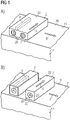
- FIG 1A an example of a ventilation body 2 for an electrically described vehicle 10 is shown.
- the ventilation body 2 is located on a vehicle roof 11 and has a plurality of ventilation openings 20 which are attached to opposite sides of the ventilation body 2 .
- Figure 1A only the ventilation openings 20 on one ventilation side 21 are shown, the ventilation openings on an opposite ventilation side 22 cannot be seen.
- Braking resistors 9 are cooled by an air flow through ventilation openings 20 , specifically from ventilation side 21 to ventilation side 22 .
- the ventilation openings 20 are circular in shape, for example, and can have a grating.
- a plurality of ventilation bodies 2 are preferably arranged next to one another along the direction of travel D, in contrast to the illustration in FIG Figure 1A . This preferably also applies to all other exemplary embodiments.
- the aeration bodies 2 each have a fan 23 in order to drive the air flow along the air flow direction A in a defined manner.
- only two ventilation openings 20 lying opposite one another can be provided in each ventilation body 2 .
- the height of the ventilation bodies 2 is, for example, at least 0.2 m and/or at most 0.6 m, in particular around 0.4 m.
- the ventilation sides 21 and the ventilation sides 22 are oriented approximately parallel to the side surfaces 12 of the vehicle.
- An extension of all ventilation bodies 2 of a heat sink cover 1 along the direction of travel D is, for example, 7.5 m.
- a total length of the heat sink cover 1 is, for example, 8.2 m.
- the configurations of the ventilation bodies 2, as shown in FIGS. 1A and 1B, can be present correspondingly in all other exemplary embodiments.
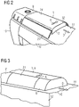
- FIG 2 is schematically illustrated that the ventilation body 2 are housed in the heat sink cover 1.
- the heat sink cover 1 optionally has a housing roof 24 which is aligned approximately parallel to the vehicle roof 11 .
- Top sides of the ventilation bodies 2 can form part of the housing roof 24 or the housing roof 24 completely covers these top sides.
- Both the vehicle roof 11, the optional housing roof 24 and the vehicle side surfaces 12 can be curved when viewed in cross section.
- One or, preferably, several inlet flaps 31 and one or, preferably, several outlet flaps 32 are located on the ventilation bodies 2 laterally and along the direction of travel D.
- the flaps 31, 32 together with the optional housing roof 24 fit flush into the roof lining 8.
- the 8 headliner puts, unlike in figure 2 drawn, along the direction of travel D on both sides of the heatsink cover 1 continues. This is additionally in figure 3 illustrated. This means that the ventilation bodies are in the closed state of the flaps 31, 32 2, possibly with the exception of their upper sides, are preferably completely hidden and do not offer any flow attack surface.
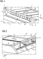
- FIG 4 an example of the design on the ventilation side 21 is illustrated.
- the vent side in figure 4 not shown, can be implemented in the same way.
- the inlet flap 31 is shown open.
- the inlet flap 31 is folded in, beginning at the vehicle roof 11, and in the folded state runs approximately parallel to the vehicle roof 11.
- the ventilation openings 20 are fully exposed.
- a cover plate 74 is optionally present. In the direction away from the ventilation bodies 2 , the cover plate 74 protrudes beyond the ventilation openings 20 as an extension of the housing roof 24 .
- the cover plate 74 preferably widens at one end and at the beginning of the inlet flap 31 along the direction of travel D. In relation to a distance between an outer edge of the inlet flap 31 and the ventilation body 2, the cover plate 24 has, for example, an extension of at least 10% or 20% and/or at most 40% or 30% of this distance.
- the heatsink cover 1 preferably has fixed transition plates 73 which are located at a beginning and at an end of the inlet flap 31 .
- the transition plates 73 each narrow in the direction away from the vehicle roof 11 and in the direction away from the ventilation bodies 2 .
- Such transition plates 73 can also be present in all other exemplary embodiments.
- FIG 5 Another example of the heat sink cover 1 is illustrated using the ventilation side 22.
- the ventilation side not shown, can be designed the same as the ventilation side 22, unless otherwise explained.
- the outlet flap 32 has a lower part 5 and an upper part 6 .
- the lower part 5 is fixed and, viewed in cross section, follows a contour of figure 5 undrawn roof lining.
- the upper part 6 bends at an upper edge 56 away from the lower part 5 in the direction of the vehicle roof.
- a ramp is temporarily formed by the upper part 6 in the direction away from the ventilation body 2, see also figure 7 .
- One or more bulkheads 71 are optionally present.
- the bulkheads 71 are oriented perpendicular to the direction of travel D.
- At least one wind deflector 72 can be located on the bulkheads 71, see also figure 8 .
- the wind deflector 72 In the closed state of the outlet flap 32, the wind deflector 72 preferably does not protrude beyond the associated bulkhead 71, compare Figure 8A .
- the wind deflector 72 projects beyond the associated bulkhead 71, see FIG Figures 8B and 8C .
- the wind deflector 72 can run straight, as an extension of the bulkhead 71, see FIG Figure 8C .
- Such wind deflectors 72 are preferably only activated on the ventilation side 22 and not on the ventilation side 21.
- the bulkhead 71 together with the optional wind deflector 22 creates a negative flow pressure in the area of the ventilation openings 20 generated so that the air guided through the ventilation body 2 can escape more easily from the ventilation opening 20 on the ventilation side 22 .
- an empty chamber 76 in front of the first bulkhead 71 in the direction of travel.
- the bulkhead 71 with the optional wind deflector 72 and the associated ventilation openings 20 begin directly on an end face 75 of the heat sink cover 1.
- An expansion of the optional empty chamber 76 along the direction of travel D is, for example, at least 0.1 m or 0.2 m and/or at most 0.8 m or 0.6 m is opened by a speed of the vehicle, for example only at comparatively high speeds.
- FIG 6 it is illustrated that the housing 1 fits into the roof lining 8 when viewed in cross section and a profile of the roof lining 8 does not change when the flaps 31, 32 are in the closed state.
- the vehicle 10, which is a high-speed train, for example, has a K4 value in the range of around 5 m 2 .
- the heat sink cover 1 described here reduces the K4 value by approximately 0.3 m 2 compared to a configuration without such flaps 31, 32. This means that the flaps 31, 32 reduce the K4 value and thus the driving resistance by approx 5% reducible. This applies in particular at speeds above 120 km/h.
- the components shown in the figures preferably follow in the order given each directly to each other. Layers that are not touching in the figures are preferably spaced apart from one another. Insofar as lines are drawn parallel to one another, the corresponding areas are preferably also aligned parallel to one another. Likewise, unless otherwise indicated, the relative positions of the drawn components to one another are correctly reproduced in the figures.
Landscapes
- Engineering & Computer Science (AREA)
- Mechanical Engineering (AREA)
- Transportation (AREA)
- Microelectronics & Electronic Packaging (AREA)
- Wood Science & Technology (AREA)
- Life Sciences & Earth Sciences (AREA)
- Automation & Control Theory (AREA)
- Power Engineering (AREA)
- Cooling, Air Intake And Gas Exhaust, And Fuel Tank Arrangements In Propulsion Units (AREA)
- Electric Propulsion And Braking For Vehicles (AREA)
- Body Structure For Vehicles (AREA)
- Secondary Cells (AREA)
- Automatic Cycles, And Cycles In General (AREA)
- Air-Conditioning For Vehicles (AREA)
Description
- Es wird ein elektrisch betriebenes Fahrzeug angegeben.
- Die Druckschrift
WO 2017/060032 A1 ist auf ein Verfahren zum Betreiben eines Fahrzeugs und auf ein Fahrzeug gerichtet. - In der Druckschrift
DE 10 2010 026 337 A1 ist ein Schienenfahrzeug mit fahrtwindgekühltem Bremswiderstand beschrieben. - Ein Verfahren zum zeitweiligen Erhöhen eines Luftwiderstands eines wenigstens zwei aneinandergekoppelte Wagenkästen aufweisenden Schienenfahrzeugs findet sich in der Druckschrift
DE 10 2013 221 551 A1 . - Die Druckschrift
DE 10 2013 226 719 A1 ist auf ein Dachgehäuse für Schienenfahrzeuge gerichtet. - Eine zu lösende Aufgabe liegt darin, ein Fahrzeug mit einer Kühlkörperabdeckung anzugeben, mit der eine effiziente Kühlung ermöglicht wird und die einen reduzierten Luftwiderstand aufweist.
- Diese Aufgabe wird durch ein Fahrzeug mit den Merkmalen des unabhängigen Patentanspruchs gelöst. Bevorzugte Weiterbildungen sind Gegenstand der abhängigen Ansprüche.
- Gemäß der Erfindung weist ein elektrisch betriebenes Fahrzeug ein Fahrzeugdach, mindestens eine Kühlkörperabdeckung sowie zumindest einen Bremswiderstand in einem Durchlüftungskörper der zumindest einen Kühlkörperabdeckung auf. Bei dem Fahrzeug handelt es sich bevorzugt um ein elektrisch betriebenes Fahrzeug wie ein Zug.
- Erfindungsgemäß umfasst die Kühlkörperabdeckung oder befindet sich in oder an der Kühlkörperabdeckung ein oder mehrere Durchlüftungskörper. Insofern kann die Kühlkörperabdeckung als Kühlkörpergehäuse aufgefasst werden. In dem mindestens einen Durchlüftungskörper befinden sich Lüftungsöffnungen. Die Lüftungsöffnungen sind zu einem Lufteintritt sowie zu einem Luftaustritt vorgesehen.
- Erfindungsgemäß weist der Durchlüftungskörper eine Luftdurchstromrichtung auf. Es ist möglich, dass die Luftdurchstromrichtung entlang einer geraden Linie verläuft, im Mittel gesehen und Verwirbelungen nicht berücksichtigt. Insbesondere stellt die Luftdurchstromrichtung eine Verbindungsachse zwischen zwei einander zugeordneten, gegenüberliegenden Lüftungsöffnungen des Durchlüftungskörpers dar.
- Erfindungsgemäß ist die Luftdurchstromrichtung quer zu einer Fahrtrichtung des Fahrzeugs orientiert. Insbesondere steht die Luftdurchstromrichtung senkrecht zur Fahrtrichtung. Dabei ist es möglich, dass die Luftdurchstromrichtung sowie die Fahrtrichtung parallel zu einer Bodenfläche, insbesondere Schienen, auf der sich das Fahrzeug bewegt, orientiert sind. Das heißt, die Fahrtrichtung und die Luftdurchstromrichtung können im Mittel horizontal ausgerichtet sein.
- Erfindungsgemäß umfasst die Kühlkörperabdeckung eine oder mehrere Einlassklappen sowie eine oder mehrere Auslassklappen. Die mindestens eine Einlassklappe befindet sich an einer Belüftungsseite des Durchlüftungskörpers und die mindestens eine Auslassklappe befindet sich an einer Entlüftungsseite des Durchlüftungskörpers. An der Belüftungsseite tritt Umgebungsluft in den Durchlüftungskörper ein und wird an der Entlüftungsseite aus dem Durchlüftungskörper ausgeblasen. Der Entlüftungsseite und der Belüftungsseite sind entsprechende Lüftungsöffnungen des Durchlüftungskörpers zugeordnet. Es ist möglich, dass im Betrieb des Fahrzeugs die Entlüftungsseite und die Belüftungsseite ihre Rollen vertauschen, beispielsweise abhängig von einer Fahrrichtung des Fahrzeugs. Alternativ sind die Entlüftungsseite und die Belüftungsseite zeitlich unveränderlich.
- Erfindungsgemäß sind die Einlassklappe und die Auslassklappe in geschlossenem Zustand längs der Fahrtrichtung des Fahrzeugs ausgerichtet. Mit anderen Worten können Längsachsen der Einlassklappe und/oder der Auslassklappe parallel zur Fahrtrichtung orientiert sein. Sind mehrere Einlassklappen und/oder Auslassklappen vorhanden, so gilt dies bevorzugt für eine Gesamtheit der Einlassklappen und/oder der Auslassklappen. Dass die Einlassklappe und die Auslassklappe in geschlossenem Zustand längs der Fahrtrichtung des Fahrzeugs ausgerichtet kann bedeuten, dass durch die Einlassklappe und die Auslassklappe kein oder kein signifikanter Luftwiderstand erzeugt wird. Das heißt, Außenflächen und/oder die Längsachsen der Einlassklappe und der Auslassklappe können parallel zur Fahrtrichtung des Fahrzeugs orientiert sein, beispielsweise mit einer Toleranz von höchstens 20° oder 5° oder 1°.
- Erfindungsgemäß sind die Einlassklappe und die Auslassklappe schräg zur Luftdurchstromrichtung ausgerichtet. Dies gilt insbesondere in geschlossenem Zustand der Einlassklappe und der Auslassklappe.
- Erfindungsgemäß sind die Lüftungsöffnungen in Draufsicht gesehen, insbesondere in Richtung parallel zur Luftdurchstromrichtung gesehen, in geschlossenem Zustand zu mindestens 90 % oder 95 % oder vollständig von der je zugehörigen Einlassklappe sowie von der je zugehörigen Auslassklappe bedeckt. Ein Bedeckungsgrad der Lüftungsöffnungen in geöffnetem Zustand durch die Einlassklappe und/oder die Auslassklappe liegt bevorzugt bei höchstens 70 % oder 60 % oder 50 % oder 40 %. Es ist möglich, dass in geöffnetem Zustand die Lüftungsöffnungen in Draufsicht gesehen frei von der Einlassklappe und/oder der Auslassklappe sind.
- Erfindungsgemäß ist das Fahrzeug elektrisch betrieben. Dies bedeutet insbesondere, dass das Fahrzeug über einen Elektromotor verfügt, über den eine Antriebskraft des Fahrzeugs für Räder des Fahrzeugs erzeugt wird. Bei dem elektrisch betriebenen Fahrzeug handelt es sich beispielsweise um einen Zug, eine Straßenbahn oder ein teilweise oder vollständig elektrisch betriebenes Straßenfahrzeug wie ein Auto oder ein Lastkraftwagen.
- Erfindungsgemäß weist das Fahrzeug ein Fahrzeugdach auf. Dabei ist es möglich, dass das Fahrzeugdach gekrümmt ist. Das Fahrzeugdach kann im Mittel horizontal ausgerichtet sein.
- Erfindungsgemäß weist das Fahrzeug einen oder mehrere Bremswiderstände auf. Der mindestens eine Bremswiderstand ist in dem Durchlüftungskörper untergebracht oder es sind mehrere Bremswiderstände in einem Durchlüftungskörper untergebracht oder es sind mehrere Bremswiderstände über mehrere Durchlüftungskörper hinweg verteilt untergebracht. Bei dem Bremswiderstand handelt es sich insbesondere um einen Belastungswiderstand einer Widerstandsbremse, der im generatorischen Betrieb eines Elektromotors eine Last darstellt, die den Motor belastet und abbremst.
- Erfindungsgemäß sind die Einlassklappe und die Auslassklappe symmetrisch zu einer Fahrzeugmittelachse angeordnet. Das heißt, durch eine Spiegelung an der Fahrzeugmittelachse lässt sich die Einlassklappe in die Auslassklappe geometrisch abbilden und umgekehrt. Dies gilt insbesondere hinsichtlich einer äußeren Kontur der Einlassklappe sowie der Auslassklappe. Die Fahrzeugmittelachse steht senkrecht zur Fahrtrichtung und vertikal. Insbesondere ist die Fahrzeugmittelachse eine Spurachse und/oder befindet sich mittig zwischen Rädern des Fahrzeugs. Die Fahrzeugmittelachse kann sich auf eine Außenkontur des Fahrzeugs beziehen.
- Erfindungsgemäß sind die Lüftungsöffnungen mit einer Toleranz von höchstens 40°, insbesondere höchstens 20° oder 10° oder 5°, parallel zu Seitenflächen des Fahrzeugs ausgerichtet. Die Lüftungsöffnungen können im Mittel vertikal ausgerichtet sein.
- Erfindungsgemäß sind die Einlassklappe und die Auslassklappe im geschlossenen Zustand längs der Fahrtrichtung und schräg zur Luftdurchstromrichtung ausgerichtet. In Draufsicht auf die Lüftungsöffnungen gesehen sind diese von der Einlassklappe und der Auslassklappe im geschlossenen Zustand zu mindestens 90 % und in geöffnetem Zustand zu höchstens 60 % bedeckt. Die Einlassklappe und die Auslassklappe sind bevorzugt symmetrisch zu einer Fahrzeugmittelachse angeordnet und die Lüftungsöffnungen sind mit einer Toleranz von höchstens 40° parallel zu Seitenflächen des Fahrzeugs ausgerichtet.
- Das Fahrzeug weist also insbesondere einen fahrwiderstandsoptimierten Bremswiderstand auf, der in dem Durchlüftungskörper angebracht ist und/oder der den Durchlüftungskörper bildet. Der Durchlüftungskörper und/oder der Bremswiderstand verfügen über vergleichsweise große Hohlkammern, die einen Fahrwiderstand vergrößern können. Dabei entsteht in diesen Hohlkammern, wo insbesondere Wärmetauscher und/oder Widerstandselemente verbaut sind, durch den Fahrtwind ein Gegendruck, der zu Verwirbelungen und somit zu einer Fahrtwiderstandserhöhung führt. Dabei liegt die Durchströmungsrichtung herkömmlicherweise in Fahrtrichtung oder entgegen der Fahrtrichtung. Solche Bremswiderstände oder Durchlüftungskörper weisen üblicherweise keine Verschlüsse auf, die ein Eindringen von Fahrtwind während einer Inaktivität verhindern. Alle Bereiche werden durchströmt, insbesondere permanent durchströmt. Es werden beispielsweise versenkbare Luftansauger verwendet, mit einer Strömungsausrichtung in Fahrtrichtung.
- Bei der hier beschriebenen Konfiguration ist eine Durchströmungsrichtung der Bremswiderstände und/oder des Durchlüftungskörpers 90° zur Fahrtrichtung orientiert. Die Bremswiderstände und/oder der Durchlüftungskörper sind durch Anbauteile verkleidet. Die Bereiche an einem Lufteinlass sowie an einem Luftauslass sind durch bewegliche Klappen verschließbar. Wenn erforderlich, werden die Klappen geöffnet, um eine Durchströmung des Bremswiderstands und/oder des Durchlüftungskörpers zu ermöglichen. Einlaufbereiche und Auslaufbereiche sowie Schottwände optimieren bevorzugt eine Luftführung und minimieren Störgeräusche. Dazu befinden sich solche Schottwände und/oder Windabweiser bevorzugt auf der Luftauslassseite.
- Mit der hier beschriebenen Kühlkörperabdeckung ist eine Effizienzsteigerung des Zugs möglich, da sich der Fahrwiderstand reduziert. Es wird eine energieeffiziente Belüftung der Bremswiderstände erreicht, da kleinere Lüfter mit weniger Leistung verwendet werden können, im Vergleich zu einer Konfiguration ohne Klappen. Es ist eine geringere akustische Wahrnehmbarkeit im Innenraum des Zuges und/oder außerhalb des Zuges gegeben. Dies wird insbesondere durch die verschließbaren Klappen zur Fahrtwiderstandsminimierung erreicht, die mit weniger Störungen einer Luftströmung um den Zug einhergehen.
- Insgesamt ist somit ein energieeffizienteres und leiseres Fahrzeug erreichbar.
- Erfindungsgemäß weisen die Einlassklappe und die Auslassklappe je ein feststehendes Unterteil näher an dem Fahrzeugdach und ein bewegliches Oberteil weiter von dem Fahrzeugdach entfernt auf. Die Unterteile bedecken die Lüftungsöffnungen in Draufsicht auf diese gesehen, insbesondere entlang parallel der Luftdurchstromrichtung gesehen, zu mindestens 25 %, insbesondere zu mindestens 35 %, und zu höchstens 60 %, insbesondere zu höchstens 50 % oder 40 %.
- Gemäß zumindest einer Ausführungsform sind die Oberteile im geöffneten Zustand schräg zum Fahrzeugdach orientiert. Dabei können die Oberteile eine Rampe in Richtung weg von den Lüftungsöffnungen hin zu einer dem Fahrzeugdach abgewandten Oberkante der Unterteile bilden. Hierdurch ist eine Strömung durch den Durchlüftungskörper hindurch durch die Klappen weniger gestört.
- Gemäß zumindest einer Ausführungsform geben die Einlassklappe und/oder die Auslassklappe im geöffneten Zustand die Lüftungsöffnungen mindestens zu 90 % oder vollständig frei. Dies gilt insbesondere in Draufsicht entlang der Luftdurchstromrichtung gesehen.
- Insbesondere können die Einlassklappe und/oder die Auslassklappe im geöffneten Zustand mit einer Toleranz von höchstens 20° oder 10° oder 5° oder 1° parallel zum Fahrzeugdach verlaufen. Dies gilt speziell für Außenflächen der Einlassklappe und/oder die Auslassklappe. Mit anderen Worten können sich die Klappen im geöffneten Zustand an das Fahrzeugdach anschmiegen. Dies gilt insbesondere, wenn die Klappen die Lüftungsöffnungen in geöffnetem Zustand vollständig freigeben.
- Gemäß zumindest einer Ausführungsform weist das Fahrzeug, insbesondere die Kühlkörperabdeckung, eine oder mehrere feststehende Schottwände auf. Das heißt, die Schottwand wird im bestimmungsgemäßen Gebrauch nicht oder nicht signifikant bewegt.
- Die mindestens eine Schottwand ist mit einer Toleranz von höchstens 20°, insbesondere höchstens 10° oder 2°, senkrecht zur Fahrtrichtung orientiert. Insbesondere stehen die Schottwände senkrecht zur Fahrtrichtung.
- Dabei schließt die mindestens eine Schottwand im geschlossenen Zustand der Einlassklappe und/oder der Auslassklappe bündig mit einer Außenseite und/oder einer Innenseite der Einlassklappe und/oder der Auslassklappe ab. Mit anderen Worten kann eine Kante der Schottwand, die dem Durchlüftungskörper abgewandt ist, entlang einer äußeren Kontur der Kühlkörperabdeckung verlaufen. Dies gilt speziell in einem Querschnitt senkrecht zur Fahrtrichtung gesehen.
- Gemäß zumindest einer Ausführungsform ist an der Schottwand oder an zumindest einer der Schottwände oder an einigen der Schottwände oder an allen Schottwänden ein Windabweiser angebracht. Der Windabweiser überragt in geschlossenem Zustand der Einlassklappe und der Auslassklappe diese bevorzugt nicht. Das heißt, im geschlossenen Zustand der Klappen kann der Windabweiser eingefahren sein. Es ist möglich, dass die Windabweiser auf die Entlüftungsseite beschränkt sind und/oder an der Belüftungsseite nicht betrieben werden. Beispielsweise ist der Windabweiser ausfahrbar oder ausklappbar in der zugehörigen Schottwand gelagert. Das heißt in geschlossenem Zustand der Klappen kann der Windabweiser bündig mit der Schottwand abschließen, in Richtung weg von dem Durchlüftungskörper.
- Weiterhin überragen die Windabweiser in geöffnetem Zustand der Einlassklappe und der Auslassklappe die zugehörige Schottwand und/oder eine Außenkontur der Kühlkörperabdeckung. Das heißt, bei geöffneten Klappen werden die Windabweiser ausgefahren, insbesondere nur an der Entlüftungsseite.
- Gemäß zumindest einer Ausführungsform weist die Kühlkörperabdeckung mehrere Übergangsplatten auf. Die Übergangsplatten begrenzen die Kühlkörperabdeckung beiderseits, längs der Fahrtrichtung gesehen. Durch die Übergangsplatten ist ein Strömungsverhalten an einem Beginn und an einem Ende der Kühlkörperabdeckung, speziell entlang der Fahrtrichtung gesehen, optimierbar. Die Übergangsplatten entfalten ihre Wirkung bevorzugt nur bei geöffneten Klappen. Bei geschlossenen Klappen liegen die Übergangsplatten bevorzugt in der Außenkontur der Kühlkörperabdeckung und/oder einer Dachverkleidung des Fahrzeugs.
- Dabei verschmälern sich die Übergangsplatten in Richtung weg von dem Fahrzeugdach kontinuierlich. Dies kann in Draufsicht und/oder in Seitenansicht des Fahrzeugs gelten.
- Gemäß einer alternativen Ausführungsform weist die Kühlkörperabdeckung mehrere Deckplatten auf. Die Deckplatten, die durch ein dünnes Blech oder durch eine dünne Kunststoffplatte realisiert sein können und flächig gestaltet sind, sind bevorzugt parallel oder näherungsweise parallel zum Fahrzeugdach ausgerichtet. Dies gilt beispielsweise mit einer Toleranz von höchstens 10°, insbesondere höchstens 5° oder 2°. Die Deckplatten sind bevorzugt feststehend und starr, können alternativ aber auch beweglich gelagert sein und sich bei einem Öffnen und/oder Schließen der Klappen mitbewegen.
- Die Deckplatten können dabei die zugehörigen Lüftungsöffnungen in Richtung weg von dem Durchlüftungskörper an einer dem Fahrzeugdach abgewandten Seite überragen. Mit anderen Worten kann die Deckplatte eine Art Vordach der zugeordneten Lüftungsöffnung darstellen.
- Gemäß zumindest einer Ausführungsform ist in dem Durchlüftungskörper mindestens ein Ventilator angebracht. Der eine oder die mehreren Ventilatoren sind zur Erzeugung eines Luftstroms durch den Durchlüftungskörper eingerichtet, sodass durch den Luftstrom eine Kühlung des Bremswiderstands erfolgt. Mit anderen Worten ist durch die Ventilatoren die Luftdurchstromrichtung definiert. Eine Luftdurchströmung des Durchlüftungskörpers geht damit bevorzugt tatsächlich auf den zumindest einen Ventilator zurück und weniger oder nur untergeordnet oder nicht signifikant auf eine Eigenbewegung des Fahrzeugs. Es ist möglich, dass eine Laufrichtung und damit die Luftdurchstromrichtung mittels des Ventilators einstellbar sind, beispielsweise abhängig davon, ob das Fahrzeug vorwärts oder rückwärts fährt.
- Gemäß der Ausführungsform weisen die Einlassklappe und/oder die Auslassklappe im geschlossenen Zustand einen mittleren Winkel zum Fahrzeugdach auf, der zwischen einschließlich 20° 50° liegt. Im Querschnitt gesehen kann sich dieser Winkel alternativ oder zusätzlich auf eine horizontale Linie beziehen, die im Mittel parallel zum Fahrzeugdach verläuft. Der mittlere Winkel bezieht sich beispielsweise im Querschnitt gesehen auf eine Sehne der Klappen und/oder des Fahrzeugdachs.
- Weiterhin gemäß der Ausführungsform verlaufen die Einlassklappe und/oder die Auslassklappe sowie optional die mindestens eine Deckplatte längs der Fahrtrichtung sowie insbesondere quer zur Fahrtrichtung bündig mit der Dachverkleidung. Das heißt, im geschlossenen Zustand der Klappen erscheint die Kühlkörperabdeckung zusammen mit der Dachverkleidung als eine bevorzugt glatte, parallel zur Fahrtrichtung verlaufende, unstrukturierte einheitliche Fläche. Hierdurch wird im geschlossenen Zustand der Klappen ein besonders niedriger Fahrwiderstand erreicht.
- Weiterhin gemäß der Ausführungsform ist das Fahrzeug ein elektrisch angetriebener Zug. Besonders bevorzugt ist der Zug für eine Maximalgeschwindigkeit von mindestens 160 km/h, insbesondere von mindestens 220 km/h oder 280 km/h, vorgesehen. Das heißt, die hier beschriebene Kühlkörperabdeckung findet insbesondere bei Hochgeschwindigkeitszügen Anwendung, bei denen der Luftwiderstand signifikant zu einem Energieverbrauch während der Fahrt bei hohen Geschwindigkeiten beiträgt. Gemäß zumindest einer Ausführungsform umfasst die Kühlkörperabdeckung einen oder mehrere Öffnungsmechanismen. Der mindestens eine Öffnungsmechanismus ist zum Öffnen und zum Schließen der Einlassklappe sowie der Auslassklappe eingerichtet. Der Öffnungsmechanismus arbeitet insbesondere pneumatisch, hydraulisch und/oder elektrisch.
- Nachfolgend werden eine hier beschriebene Kühlkörperabdeckung und ein hier beschriebenes elektrisch betriebenes Fahrzeug unter Bezugnahme auf die Zeichnung anhand von Ausführungsbeispielen näher erläutert. Gleiche Bezugszeichen geben dabei gleiche Elemente in den einzelnen Figuren an. Es sind dabei jedoch keine maßstäblichen Bezüge dargestellt, vielmehr können einzelne Elemente zum besseren Verständnis übertrieben groß dargestellt sein.
- Es zeigen:
-
Figur 1 schematische perspektivische Darstellungen von Durchlüftungskörpern für hier beschriebene Kühlkörperabdeckungen, -
Figuren 2 und 3 schematische perspektivische Darstellungen von hier beschriebenen Fahrzeugen mit hier beschriebenen Kühlkörperabdeckungen, -
Figuren 4 und 5 schematische perspektivische Darstellungen von Ausführungsbeispielen von hier beschriebenen Kühlkörperabdeckungen, und -
Figuren 6 bis 8 schematische Schnittdarstellungen von Ausführungsbeispielen von hier beschriebenen Kühlkörperabdeckungen. - In
Figur 1A ist ein Beispiel eines Durchlüftungskörpers 2 für ein elektrisch beschriebenes Fahrzeug 10 dargestellt. Der Durchlüftungskörper 2 befindet sich auf einem Fahrzeugdach 11 und weist mehrere Lüftungsöffnungen 20 auf, die an einander gegenüberliegenden Seiten des Durchlüftungskörpers 2 angebracht sind. InFigur 1A sind lediglich die Lüftungsöffnungen 20 an einer Belüftungsseite 21 dargestellt, die Lüftungsöffnungen an einer gegenüberliegenden Entlüftungsseite 22 sind nicht zu erkennen. - In dem Durchlüftungskörper 2 befinden sich mehrere Bremswiderstände 9, von denen exemplarisch nur einer schematisch dargestellt ist. Eine Kühlung der Bremswiderstände 9 erfolgt durch einen Luftstrom durch die Lüftungsöffnungen 20 hindurch, und zwar von der Belüftungsseite 21 hin zur Entlüftungsseite 22. Dadurch ist eine Luftdurchstromrichtung A gegeben, welche senkrecht zu einer Fahrtrichtung D des Fahrzeugs 10 orientiert ist.
- Die Lüftungsöffnungen 20 sind beispielsweise kreisförmig gestaltet und können eine Vergitterung aufweisen. Bevorzugt sind mehrere der Durchlüftungskörper 2 entlang der Fahrtrichtung D nebeneinander angeordnet, abweichend von der Darstellung von
Figur 1A . Dies gilt bevorzugt auch für alle anderen Ausführungsbeispiele. - Gemäß
Figur 1B weisen die Durchlüftungskörper 2 jeweils einen Ventilator 23 auf, um den Luftstrom entlang der Luftdurchstromrichtung A definiert anzutreiben. Dabei können in jedem Durchlüftungskörper 2 nur zwei einander gegenüberliegende Lüftungsöffnungen 20 vorgesehen sein. - Eine Höhe der Durchlüftungskörper 2 liegt beispielsweise bei mindestens 0,2 m und/oder bei höchstens 0,6 m, insbesondere um 0,4 m. Die Belüftungsseiten 21 sowie die Entlüftungsseiten 22 sind näherungsweise parallel zu den Seitenflächen 12 des Fahrzeugs orientiert. Eine Ausdehnung aller Durchlüftungskörper 2 einer Kühlkörperabdeckung 1 entlang der Fahrtrichtung D liegt beispielsweise um 7,5 m. Eine Gesamtlänge der Kühlkörperabdeckung 1 beträgt beispielsweise 8,2 m.
- Die Konfigurationen der Durchlüftungskörper 2, wie in den Figuren 1A und 1B dargestellt, können entsprechend in allen anderen Ausführungsbeispielen vorliegen.
- In
Figur 2 ist schematisch illustriert, dass die Durchlüftungskörper 2 in der Kühlkörperabdeckung 1 untergebracht sind. Die Kühlkörperabdeckung 1 weist optional ein Gehäusedach 24 auf, das näherungsweise parallel zum Fahrzeugdach 11 ausgerichtet ist. Oberseiten der Durchlüftungskörper 2 können einen Teil des Gehäusedachs 24 bilden oder das Gehäusedach 24 überdeckt diese Oberseiten vollständig. - Dabei können sowohl das Fahrzeugdach 11, das optionale Gehäusedach 24 sowie die Fahrzeugseitenflächen 12 im Querschnitt gesehen gekrümmt gestaltet sein. Seitlich und längs der Fahrtrichtung D befindet sich an den Durchlüftungskörpern 2 eine oder, bevorzugt, mehrere Einlassklappen 31 sowie eine oder, bevorzugt, mehrere Auslassklappen 32. Die Klappen 31, 32 zusammen mit dem optionalen Gehäusedach 24 fügen sich bündig in die Dachverkleidung 8. Die Dachverkleidung 8 setzt sich, anders als in
Figur 2 gezeichnet, entlang der Fahrtrichtung D beiderseits der Kühlkörperabdeckung 1 fort. Dies ist zusätzlich inFigur 3 illustriert. Das heißt, im geschlossenen Zustand der Klappen 31, 32 sind die Durchlüftungskörper 2, eventuell mit Ausnahme von deren Oberseiten, bevorzugt vollständig verborgen und bieten keine Strömungsangriffsfläche. - In
Figur 4 ist ein Beispiel für die Gestaltung an der Belüftungsseite 21 illustriert. Die Entlüftungsseite, inFigur 4 nicht dargestellt, kann genauso ausgeführt sein. InFigur 4 ist die Einlassklappe 31 geöffnet dargestellt. - Die Einlassklappe 31 ist, beginnend am Fahrzeugdach 11, eingeklappt und verläuft in eingeklapptem Zustand näherungsweise parallel zum Fahrzeugdach 11. Die Lüftungsöffnungen 20 sind vollständig freigegeben.
- Optional ist eine Deckplatte 74 vorhanden. In Richtung weg von den Durchlüftungskörpern 2 steht die Deckplatte 74 in Verlängerung des Gehäusedachs 24 über die Lüftungsöffnungen 20 über. An einem Ende und an einem Anfang der Einlassklappe 31 längs der Fahrtrichtung D verbreitert sich die Deckplatte 74 bevorzugt. Bezogen auf einen Abstand einer Außenkante der Einlassklappe 31 zu dem Durchlüftungskörper 2 weist die Deckplatte 24 zum Beispiel eine Ausdehnung von mindestens 10 % oder 20 % und/oder von höchstens 40 % oder 30 % dieses Abstands auf.
- Ferner weist die Kühlkörperabdeckung 1 bevorzugt feststehende Übergangsplatten 73 auf, die sich an einem Anfang und an einem Ende der Einlassklappe 31 befinden. In Richtung weg von dem Fahrzeugdach 11 sowie in Richtung weg von den Durchlüftungskörpern 2 verschmälern sich die Übergangsplatten 73 jeweils. Solche Übergangsplatten 73 können auch in allen anderen Ausführungsbeispielen vorhanden sein.
- In
Figur 5 ist ein weiteres Beispiel der Kühlkörperabdeckung 1 illustriert, anhand der Entlüftungsseite 22. Die Belüftungsseite, nicht gezeichnet, kann gleich der Entlüftungsseite 22 ausgeführt sein, sofern nicht abweichend erläutert. - Die Auslassklappe 32 weist ein Unterteil 5 sowie ein Oberteil 6 auf. Das Unterteil 5 ist feststehend und folgt im Querschnitt gesehen einer Kontur der in
Figur 5 nicht gezeichneten Dachverkleidung. An einer Oberkante 56 knickt das Oberteil 6 in geöffnetem Zustand von dem Unterteil 5 in Richtung hin zum Fahrzeugdach ab. Dadurch wird durch das Oberteil 6 zeitweise eine Rampe in Richtung weg von dem Durchlüftungskörper 2 gebildet, siehe auchFigur 7 . - Optional ist eine oder sind mehrere Schottwände 71 vorhanden. Die Schottwände 71 sind senkrecht zur Fahrtrichtung D orientiert.
- An den Schottwänden 71 kann sich zumindest ein Windabweiser 72 befinden, siehe auch
Figur 8 . In geschlossenem Zustand der Auslassklappe 32 überragt der Windabweiser 72 die zugehörige Schottwand 71 bevorzugt nicht, vergleicheFigur 8A . Bei geöffneter Auslassklappe 32 dagegen steht der Windabweiser 72 über die zugehörige Schottwand 71 über, siehe dieFiguren 8B und 8C . Dabei kann der Windabweiser 72 gerade verlaufen, in Verlängerung der Schottwand 71, sieheFigur 8C . Alternativ ist es möglich, dass der Windabweiser 72 entgegen der Fahrtrichtung D abgewinkelt ist, sieheFigur 8B . - Bevorzugt werden solche Windabweiser 72 nur an der Entlüftungsseite 22 aktiviert und nicht an der Belüftungsseite 21.
- Durch die Schottwand 71 zusammen mit dem optionalen Windabweiser 22 wird im Bereich der Lüftungsöffnungen 20 ein Strömungsunterdruck erzeugt, sodass die durch den Durchlüftungskörper 2 geführte Luft leichter aus der Lüftungsöffnung 20 an der Entlüftungsseite 22 entweichen kann.
- Optional befindet sich vor der in Fahrtrichtung ersten Schottwand 71 eine Leerkammer 76. In der Leerkammer 76 befindet sich keine Lüftungsöffnungen 20. Alternativ beginnen die Schottwand 71 mit dem optionalen Windabweiser 72 und den zugeordneten Lüftungsöffnungen 20 direkt an einer Stirnseite 75 der Kühlkörperabdeckung 1. Eine Ausdehnung der optionalen Leerkammer 76 entlang der Fahrtrichtung D liegt beispielsweise bei mindestens 0,1 m oder 0,2 m und/oder bei höchstens 0,8 m oder 0,6 m. Bevorzugt verfügt die Leerkammer 76 über eine eigene Auslassklappe 32, die etwa abhängig von einer Geschwindigkeit des Fahrzeugs, beispielsweise nur bei vergleichsweise hohen Geschwindigkeiten, geöffnet wird.
- In
Figur 6 ist illustriert, dass sich das Gehäuse 1 im Querschnitt gesehen in die Dachverkleidung 8 fügt und ein Profil der Dachverkleidung 8 im geschlossenen Zustand der Klappen 31, 32 nicht ändert. - Das Fahrzeug 10, bei dem es sich beispielsweise um einen Hochgeschwindigkeitszug handelt, weist etwa einen K4-Wert im Bereich um 5 m2 auf. Durch die hier beschriebene Kühlkörperabdeckung 1 wird der K4-Wert um ungefähr 0,3 m2 verringert, gegenüber einer Konfiguration ohne solche Klappen 31, 32. Das heißt, mittels der Klappen 31, 32 ist der K4-Wert und damit der Fahrwiderstand um zirka 5 % reduzierbar. Dies gilt insbesondere bei Geschwindigkeiten oberhalb von 120 km/h.
- Die in den Figuren gezeigten Komponenten folgen, sofern nicht anders kenntlich gemacht, bevorzugt in der angegebenen Reihenfolge jeweils unmittelbar aufeinander. Sich in den Figuren nicht berührende Schichten sind bevorzugt voneinander beabstandet. Soweit Linien parallel zueinander gezeichnet sind, sind die entsprechenden Flächen bevorzugt ebenso parallel zueinander ausgerichtet. Ebenfalls, soweit nicht anders kenntlich gemacht, sind die relativen Positionen der gezeichneten Komponenten zueinander in den Figuren korrekt wiedergegeben.
- Der Schutzumfang wird durch die beiliegenden Ansprüche definiert.
Claims (9)
- Elektrisch betriebenes Fahrzeug (10), mit- einem Fahrzeugdach (11),- mindestens einer Kühlkörperabdeckung (1), mit mindestens einem Durchlüftungskörper (2) mit Lüftungsöffnungen (20) und mit einer Luftdurchstromrichtung (A) quer zu einer Fahrtrichtung (D) des Fahrzeugs (10), mindestens einer Einlassklappe (31) an einer Belüftungsseite (21) des Durchlüftungskörpers (2) und mindestens einer Auslassklappe (32) an einer Entlüftungsseite (22) des Durchlüftungskörpers (2), wobei die Einlassklappe (31) und die Auslassklappe (32) in geschlossenem Zustand längs der Fahrtrichtung (D) und schräg zur Luftdurchstromrichtung (A) ausgerichtet sind, und die Lüftungsöffnungen (20) in Draufsicht gesehen von der mindestens einen Einlassklappe (31) und der mindestens einen Auslassklappe (32) zusammengenommen in geschlossenem Zustand zu mindestens 90 % und in geöffnetem Zustand zu höchstens 60 % überdeckt sind, und- zumindest einem Bremswiderstand (9) in dem Durchlüftungskörper (2),
wobei- die Lüftungsöffnungen (20) mit einer Toleranz von höchstens 40 Grad parallel zu Seitenflächen (12) des Fahrzeugs (10) ausgerichtet sind,- die Einlassklappe (31) und die Auslassklappe (32) je ein feststehendes Unterteil (5) näher an dem Fahrzeugdach (11) und ein bewegliches Oberteil (6) weiter von dem Fahrzeugdach (11) entfernt aufweisen,- die Einlassklappe (31) und die Auslassklappe (32) symmetrisch zu einer Fahrzeugmittelachse (M), welche senkrecht zur Fahrtrichtung (D) orientiert ist und vertikal steht, angeordnet sind, und- die Unterteile (5) die Lüftungsöffnungen (20), in Draufsicht entlang der Luftdurchstromrichtung (A) gesehen, zu mindestens 25 % und zu höchstens 60 % überdecken. - Fahrzeug (10) nach dem vorhergehenden Anspruch,
bei dem die Oberteile (6) in geöffnetem Zustand schräg zum Fahrzeugdach (11) verlaufen, im Querschnitt senkrecht zur Fahrtrichtung (D) gesehen, sodass die Oberteile (6) je eine Rampe in Richtung weg von den Lüftungsöffnungen (20) hin zu einer vom Fahrzeugdach (11) abgewandten Oberkante (56) der Unterteile (5) bilden. - Fahrzeug (10) nach Anspruch 1,
bei dem die Einlassklappe (31) und die Auslassklappe (32) in geöffnetem Zustand die Lüftungsöffnungen (20), in Draufsicht entlang der Luftdurchstromrichtung (A) gesehen, zu mindestens 90 % freigeben, wobei Außenflächen der Einlassklappe (31) und der Auslassklappe (32) in geöffnetem Zustand mit einer Toleranz von höchstens 10 Grad parallel zum Fahrzeugdach (11) verlaufen. - Fahrzeug (10) nach einem der Ansprüche 1 bis 3,bei dem an dem Fahrzeugdach (11) mehrere feststehende Schottwände (71) angebracht sind, wobei die Schottwände (71) mit einer Toleranz von höchstens 20 Grad senkrecht zur Fahrtrichtung (D) orientiert sind, undwobei die Schottwände (71) in Richtung weg von dem Durchlüftungskörper (2) mit der zugehörigen Einlassklappe (31) und/oder der zugehörigen Auslassklappe (32) in deren geschlossenem Zustand bündig abschließen.
- Fahrzeug (10) nach dem vorhergehenden Anspruch,
bei dem an den Schottwänden (71) je ein Windabweiser (72) angebracht ist,
wobei die Windabweiser (72) in geschlossenem Zustand der Einlassklappe (31) und der Auslassklappe (32) in oder an die zu-gehörige Schottwand (71) eingefahren sind und diese und/oder die zugehörige Schottwand (71) nicht überragen, und wobei die Windabweiser (72) in geöffnetem Zustand der Einlassklappe (31) und der Auslassklappe (32) ausgefahren sind und die zugehörige Schottwand (71) überragen. - Fahrzeug (10) nach einem der Ansprüche 1 bis 5,
bei dem die Kühlkörperabdeckung (1) mehrere Übergangsplatten (73) aufweist, die die Kühlkörperabdeckung (1) beiderseits entlang der Fahrtrichtung (D) begrenzen, wobei sich die Übergangsplatten (73) in Richtung weg von dem Fahrzeugdach (11) kontinuierlich verschmälern. - Fahrzeug (10) nach einem der Ansprüche 1 bis 5,
bei dem die Kühlkörperabdeckung (1) mehrere Deckplatten (74) aufweist, welche mit einer Toleranz von höchstens 10° parallel zum Fahrzeugdach (11) ausgerichtet sind und welche die Lüftungsöffnungen (20) in Richtung weg von dem Durchlüftungs-körper (2) überragen. - Fahrzeug (10) nach einem der Ansprüche 1 bis 6,bei dem in dem Durchlüftungskörper (2) mindestens ein Ventilator (23) zur Erzeugung eines Luftstroms durch den Durchlüftungskörper (2) zur Kühlung des Bremswiderstands (9) angebracht ist,wobei Außenflächen der Einlassklappe (31) und/oder der Auslassklappe (32) in geschlossenem Zustand einen mittleren Winkel zum Fahrzeugdach (11) zwischen einschließlich 20 Grad und 50 Grad aufweisen und längs der Fahrtrichtung (D) bündig mit einer Dachverkleidung (8) verlaufen, undwobei das Fahrzeug (10) ein elektrisch angetriebener Zug ist, der für eine Maximalgeschwindigkeit von mindestens 160 km/h vorgesehen ist.
- Fahrzeug nach einem der Ansprüche 1 bis 8, wobei die Kühlkörperabdeckung (1) mindestens einen Öffnungsmechanismus (4) zum Öffnen und zum Schließen der Einlassklappe (31) sowie der Auslassklappe (32) umfasst.
Applications Claiming Priority (2)
| Application Number | Priority Date | Filing Date | Title |
|---|---|---|---|
| DE102017217228.2A DE102017217228B4 (de) | 2017-09-27 | 2017-09-27 | Elektrisch betriebenes Fahrzeug |
| PCT/EP2018/076214 WO2019063667A1 (de) | 2017-09-27 | 2018-09-27 | Kühlkörperabdeckung und elektrisch betriebenes fahrzeug |
Publications (2)
| Publication Number | Publication Date |
|---|---|
| EP3658437A1 EP3658437A1 (de) | 2020-06-03 |
| EP3658437B1 true EP3658437B1 (de) | 2022-06-01 |
Family
ID=63840785
Family Applications (1)
| Application Number | Title | Priority Date | Filing Date |
|---|---|---|---|
| EP18785852.7A Not-in-force EP3658437B1 (de) | 2017-09-27 | 2018-09-27 | Kühlkörperabdeckung und elektrisch betriebenes fahrzeug |
Country Status (6)
| Country | Link |
|---|---|
| US (1) | US11097752B2 (de) |
| EP (1) | EP3658437B1 (de) |
| CN (1) | CN111148679B (de) |
| DE (1) | DE102017217228B4 (de) |
| ES (1) | ES2925541T3 (de) |
| WO (1) | WO2019063667A1 (de) |
Families Citing this family (2)
| Publication number | Priority date | Publication date | Assignee | Title |
|---|---|---|---|---|
| DE102021202091A1 (de) * | 2021-03-04 | 2022-09-08 | Siemens Mobility GmbH | Mehrlagige Bremswiderstandvorrichtung für ein Fahrzeug |
| JP2024125750A (ja) * | 2023-03-06 | 2024-09-19 | 日野自動車株式会社 | 車体下部構造 |
Family Cites Families (19)
| Publication number | Priority date | Publication date | Assignee | Title |
|---|---|---|---|---|
| US2289910A (en) * | 1939-10-21 | 1942-07-14 | B F Sturtevant Co | Pressure ventilating unit |
| JPS6164567A (ja) * | 1984-09-05 | 1986-04-02 | Japanese National Railways<Jnr> | 高速電気車両の発電ブレ−キ用抵抗器の冷却装置 |
| JPH01141163A (ja) * | 1986-02-11 | 1989-06-02 | Alsthom Atlantique Sa | 機関車の流体冷却器用及び/又は加減抵抗器用換気装置 |
| FR2693160B1 (fr) * | 1992-07-06 | 1994-08-19 | Alsthom Gec | Engin de traction ferroviaire équipé de rhéostats de freinage, pour train à grande vitesse. |
| FR2926276B1 (fr) * | 2008-01-11 | 2010-09-03 | Alstom Transport Sa | Ensemble de ventilation d'un appareillage de vehicule ferroviaire |
| RU2381113C1 (ru) * | 2008-09-15 | 2010-02-10 | Открытое акционерное общество "Людиновский тепловозостроительный завод" | Охлаждающее устройство железнодорожного транспортного средства |
| DE102010026337A1 (de) | 2010-07-07 | 2012-01-12 | Siemens Aktiengesellschaft | Schienenfahrzeug mit fahrtwindgekühltem Bremswiderstand |
| JP5480052B2 (ja) * | 2010-07-23 | 2014-04-23 | 株式会社東芝 | 鉄道車両用冷却装置 |
| JP5679796B2 (ja) * | 2010-12-17 | 2015-03-04 | 三菱電機株式会社 | 磁気フィルタを使用した車両用空気調和装置 |
| CN202254147U (zh) * | 2011-09-08 | 2012-05-30 | 广州中车轨道交通装备股份有限公司 | 轨道车辆空调机组二次新风进风结构 |
| CN103264708B (zh) * | 2013-05-24 | 2015-12-23 | 深圳市百欧森环保科技开发有限公司 | 用于轨道车的空气净化器安装机构 |
| CN103273935A (zh) * | 2013-06-20 | 2013-09-04 | 南车南京浦镇车辆有限公司 | 地铁车辆用导流风道的装配方法 |
| DE102013221551A1 (de) | 2013-10-23 | 2015-04-23 | Siemens Aktiengesellschaft | Verfahren zum zeitweiligen Erhöhen eines Luftwiderstands eines wenigstens zwei aneinandergekoppelte Wagenkästen aufweisenden Schienenfahrzeugs |
| CN203681557U (zh) * | 2013-11-28 | 2014-07-02 | 南京工业大学 | 基于吸附式制冷的地铁列车制动电阻余热利用系统 |
| FR3014396B1 (fr) * | 2013-12-06 | 2017-04-28 | Alstom Transp Tech | Dispositif de refroidissement de composants, notamment pour un vehicule ferroviaire |
| DE102013226719A1 (de) | 2013-12-19 | 2015-06-25 | Siemens Aktiengesellschaft | Dachgehäuse für ein Schienenfahrzeug |
| FR3029485B1 (fr) * | 2014-12-03 | 2018-03-16 | Alstom Transport Technologies | Dispositif aeraulique de refroidissement d'un element d'un vehicule ferroviaire et vehicule ferroviaire correspondant |
| DE102015207442A1 (de) * | 2015-04-23 | 2016-10-27 | Siemens Aktiengesellschaft | Fahrzeug mit einer zu kühlenden Fahrzeugkomponente |
| DE102015219157A1 (de) | 2015-10-05 | 2017-04-06 | Siemens Aktiengesellschaft | Verfahren zum Betreiben eines Fahrzeugs und Fahrzeug |
-
2017
- 2017-09-27 DE DE102017217228.2A patent/DE102017217228B4/de not_active Expired - Fee Related
-
2018
- 2018-09-27 ES ES18785852T patent/ES2925541T3/es active Active
- 2018-09-27 US US16/649,424 patent/US11097752B2/en not_active Expired - Fee Related
- 2018-09-27 EP EP18785852.7A patent/EP3658437B1/de not_active Not-in-force
- 2018-09-27 WO PCT/EP2018/076214 patent/WO2019063667A1/de not_active Ceased
- 2018-09-27 CN CN201880062207.8A patent/CN111148679B/zh not_active Expired - Fee Related
Also Published As
| Publication number | Publication date |
|---|---|
| DE102017217228B4 (de) | 2019-06-06 |
| CN111148679B (zh) | 2022-08-09 |
| EP3658437A1 (de) | 2020-06-03 |
| CN111148679A (zh) | 2020-05-12 |
| DE102017217228A1 (de) | 2019-03-28 |
| US20200239041A1 (en) | 2020-07-30 |
| WO2019063667A1 (de) | 2019-04-04 |
| US11097752B2 (en) | 2021-08-24 |
| ES2925541T3 (es) | 2022-10-18 |
Similar Documents
| Publication | Publication Date | Title |
|---|---|---|
| DE3837729C2 (de) | ||
| DE102010026323A1 (de) | Kühleranordnung für ein Kraftfahrzeug | |
| DE102016001899B4 (de) | Kraftfahrzeug | |
| EP3658437B1 (de) | Kühlkörperabdeckung und elektrisch betriebenes fahrzeug | |
| EP1713656B1 (de) | Kühleranordnung für ein kraftfahrzeug | |
| DE69313749T2 (de) | Mit Brems-Rheostaten ausgerüstetes Schienentriebfahrzeug für einen Hochgeschwindigkeitszug | |
| EP2799272B1 (de) | Fahrerhaus mit rückseitigem Flächenkühler | |
| DE102013221551A1 (de) | Verfahren zum zeitweiligen Erhöhen eines Luftwiderstands eines wenigstens zwei aneinandergekoppelte Wagenkästen aufweisenden Schienenfahrzeugs | |
| DE3834119A1 (de) | Bremskuehlklappen- und luftfuehrungs- system fuer fahrzeuge | |
| DE112019002434T5 (de) | Fahrzeugluftkanal, Luftkanalanordnung, Fahrzeug und Verfahren zum Steuern eines Fahrzeugluftkanals | |
| EP2333324A2 (de) | Windkraftanlage zur Erzeugung von elektrischer Energie in einem Kraftfahrzeug | |
| WO2017060032A1 (de) | Verfahren zum betreiben eines fahrzeugs und fahrzeug | |
| DE102008045596A1 (de) | Vorrichtung und Verfahren zum Kühlen einer Abgasanlage eines Kraftwagens | |
| WO2005113295A1 (de) | Schallabsorbierendes verkleidungselement | |
| EP3386831B1 (de) | Eisenbahn-triebfahrzeug mit dachübergangselement | |
| DE202018104361U1 (de) | Schließeinrichtung mit klappenförmigen Bauelementen für Ansaug- bzw. Ausblasöffnungen der Prozessluft von Klima- und Lüftungsgeräten für Schienenfahrzeuge | |
| EP0257569B1 (de) | Fahrzeug, insbesondere Omnibus, mit einem für eine Klimaanlage vorgesehenen Dachaufbau | |
| DE10209591A1 (de) | Aerodynamische Verkleidung für die Unterseite eines Kraftfahrzeugs | |
| DE102024000769A1 (de) | Luftansaugeinrichtung für ein Kraftfahrzeug, insbesondere für einen Kraftwagen, sowie Kraftfahrzeug, insbesondere Kraftwagen | |
| DE102017113340A1 (de) | Anbaugruppe, Hinterwagen und Kraftfahrzeug | |
| DE202010014870U1 (de) | Strömungskanal für ein Klimagerät | |
| CH700463A2 (de) | Windturbine für ein Fahrzeug. | |
| DE102009036758A1 (de) | Luftleiteinrichtung für einen Kraftwagen | |
| EP1427624A1 (de) | Lokomotive mit seitengängen | |
| DE2532699C2 (de) | Kraftwagen mit einer Be- und Entlüftung des Fahrgastraumes |
Legal Events
| Date | Code | Title | Description |
|---|---|---|---|
| STAA | Information on the status of an ep patent application or granted ep patent |
Free format text: STATUS: UNKNOWN |
|
| STAA | Information on the status of an ep patent application or granted ep patent |
Free format text: STATUS: THE INTERNATIONAL PUBLICATION HAS BEEN MADE |
|
| PUAI | Public reference made under article 153(3) epc to a published international application that has entered the european phase |
Free format text: ORIGINAL CODE: 0009012 |
|
| STAA | Information on the status of an ep patent application or granted ep patent |
Free format text: STATUS: REQUEST FOR EXAMINATION WAS MADE |
|
| 17P | Request for examination filed |
Effective date: 20200228 |
|
| AK | Designated contracting states |
Kind code of ref document: A1 Designated state(s): AL AT BE BG CH CY CZ DE DK EE ES FI FR GB GR HR HU IE IS IT LI LT LU LV MC MK MT NL NO PL PT RO RS SE SI SK SM TR |
|
| AX | Request for extension of the european patent |
Extension state: BA ME |
|
| DAV | Request for validation of the european patent (deleted) | ||
| DAX | Request for extension of the european patent (deleted) | ||
| GRAP | Despatch of communication of intention to grant a patent |
Free format text: ORIGINAL CODE: EPIDOSNIGR1 |
|
| STAA | Information on the status of an ep patent application or granted ep patent |
Free format text: STATUS: GRANT OF PATENT IS INTENDED |
|
| INTG | Intention to grant announced |
Effective date: 20220201 |
|
| GRAA | (expected) grant |
Free format text: ORIGINAL CODE: 0009210 |
|
| GRAS | Grant fee paid |
Free format text: ORIGINAL CODE: EPIDOSNIGR3 |
|
| STAA | Information on the status of an ep patent application or granted ep patent |
Free format text: STATUS: THE PATENT HAS BEEN GRANTED |
|
| AK | Designated contracting states |
Kind code of ref document: B1 Designated state(s): AL AT BE BG CH CY CZ DE DK EE ES FI FR GB GR HR HU IE IS IT LI LT LU LV MC MK MT NL NO PL PT RO RS SE SI SK SM TR |
|
| REG | Reference to a national code |
Ref country code: GB Ref legal event code: FG4D Free format text: NOT ENGLISH |
|
| REG | Reference to a national code |
Ref country code: AT Ref legal event code: REF Ref document number: 1495201 Country of ref document: AT Kind code of ref document: T Effective date: 20220615 Ref country code: CH Ref legal event code: EP |
|
| REG | Reference to a national code |
Ref country code: IE Ref legal event code: FG4D Free format text: LANGUAGE OF EP DOCUMENT: GERMAN |
|
| REG | Reference to a national code |
Ref country code: DE Ref legal event code: R096 Ref document number: 502018009829 Country of ref document: DE |
|
| REG | Reference to a national code |
Ref country code: LT Ref legal event code: MG9D |
|
| REG | Reference to a national code |
Ref country code: NL Ref legal event code: MP Effective date: 20220601 |
|
| REG | Reference to a national code |
Ref country code: ES Ref legal event code: FG2A Ref document number: 2925541 Country of ref document: ES Kind code of ref document: T3 Effective date: 20221018 |
|
| PG25 | Lapsed in a contracting state [announced via postgrant information from national office to epo] |
Ref country code: SE Free format text: LAPSE BECAUSE OF FAILURE TO SUBMIT A TRANSLATION OF THE DESCRIPTION OR TO PAY THE FEE WITHIN THE PRESCRIBED TIME-LIMIT Effective date: 20220601 Ref country code: NO Free format text: LAPSE BECAUSE OF FAILURE TO SUBMIT A TRANSLATION OF THE DESCRIPTION OR TO PAY THE FEE WITHIN THE PRESCRIBED TIME-LIMIT Effective date: 20220901 Ref country code: LT Free format text: LAPSE BECAUSE OF FAILURE TO SUBMIT A TRANSLATION OF THE DESCRIPTION OR TO PAY THE FEE WITHIN THE PRESCRIBED TIME-LIMIT Effective date: 20220601 Ref country code: HR Free format text: LAPSE BECAUSE OF FAILURE TO SUBMIT A TRANSLATION OF THE DESCRIPTION OR TO PAY THE FEE WITHIN THE PRESCRIBED TIME-LIMIT Effective date: 20220601 Ref country code: GR Free format text: LAPSE BECAUSE OF FAILURE TO SUBMIT A TRANSLATION OF THE DESCRIPTION OR TO PAY THE FEE WITHIN THE PRESCRIBED TIME-LIMIT Effective date: 20220902 Ref country code: FI Free format text: LAPSE BECAUSE OF FAILURE TO SUBMIT A TRANSLATION OF THE DESCRIPTION OR TO PAY THE FEE WITHIN THE PRESCRIBED TIME-LIMIT Effective date: 20220601 Ref country code: BG Free format text: LAPSE BECAUSE OF FAILURE TO SUBMIT A TRANSLATION OF THE DESCRIPTION OR TO PAY THE FEE WITHIN THE PRESCRIBED TIME-LIMIT Effective date: 20220901 |
|
| PG25 | Lapsed in a contracting state [announced via postgrant information from national office to epo] |
Ref country code: RS Free format text: LAPSE BECAUSE OF FAILURE TO SUBMIT A TRANSLATION OF THE DESCRIPTION OR TO PAY THE FEE WITHIN THE PRESCRIBED TIME-LIMIT Effective date: 20220601 Ref country code: PL Free format text: LAPSE BECAUSE OF FAILURE TO SUBMIT A TRANSLATION OF THE DESCRIPTION OR TO PAY THE FEE WITHIN THE PRESCRIBED TIME-LIMIT Effective date: 20220601 Ref country code: LV Free format text: LAPSE BECAUSE OF FAILURE TO SUBMIT A TRANSLATION OF THE DESCRIPTION OR TO PAY THE FEE WITHIN THE PRESCRIBED TIME-LIMIT Effective date: 20220601 |
|
| PG25 | Lapsed in a contracting state [announced via postgrant information from national office to epo] |
Ref country code: NL Free format text: LAPSE BECAUSE OF FAILURE TO SUBMIT A TRANSLATION OF THE DESCRIPTION OR TO PAY THE FEE WITHIN THE PRESCRIBED TIME-LIMIT Effective date: 20220601 |
|
| PG25 | Lapsed in a contracting state [announced via postgrant information from national office to epo] |
Ref country code: SM Free format text: LAPSE BECAUSE OF FAILURE TO SUBMIT A TRANSLATION OF THE DESCRIPTION OR TO PAY THE FEE WITHIN THE PRESCRIBED TIME-LIMIT Effective date: 20220601 Ref country code: SK Free format text: LAPSE BECAUSE OF FAILURE TO SUBMIT A TRANSLATION OF THE DESCRIPTION OR TO PAY THE FEE WITHIN THE PRESCRIBED TIME-LIMIT Effective date: 20220601 Ref country code: RO Free format text: LAPSE BECAUSE OF FAILURE TO SUBMIT A TRANSLATION OF THE DESCRIPTION OR TO PAY THE FEE WITHIN THE PRESCRIBED TIME-LIMIT Effective date: 20220601 Ref country code: PT Free format text: LAPSE BECAUSE OF FAILURE TO SUBMIT A TRANSLATION OF THE DESCRIPTION OR TO PAY THE FEE WITHIN THE PRESCRIBED TIME-LIMIT Effective date: 20221003 Ref country code: EE Free format text: LAPSE BECAUSE OF FAILURE TO SUBMIT A TRANSLATION OF THE DESCRIPTION OR TO PAY THE FEE WITHIN THE PRESCRIBED TIME-LIMIT Effective date: 20220601 Ref country code: CZ Free format text: LAPSE BECAUSE OF FAILURE TO SUBMIT A TRANSLATION OF THE DESCRIPTION OR TO PAY THE FEE WITHIN THE PRESCRIBED TIME-LIMIT Effective date: 20220601 |
|
| PG25 | Lapsed in a contracting state [announced via postgrant information from national office to epo] |
Ref country code: IS Free format text: LAPSE BECAUSE OF FAILURE TO SUBMIT A TRANSLATION OF THE DESCRIPTION OR TO PAY THE FEE WITHIN THE PRESCRIBED TIME-LIMIT Effective date: 20221001 |
|
| REG | Reference to a national code |
Ref country code: DE Ref legal event code: R097 Ref document number: 502018009829 Country of ref document: DE |
|
| PG25 | Lapsed in a contracting state [announced via postgrant information from national office to epo] |
Ref country code: AL Free format text: LAPSE BECAUSE OF FAILURE TO SUBMIT A TRANSLATION OF THE DESCRIPTION OR TO PAY THE FEE WITHIN THE PRESCRIBED TIME-LIMIT Effective date: 20220601 |
|
| PLBE | No opposition filed within time limit |
Free format text: ORIGINAL CODE: 0009261 |
|
| STAA | Information on the status of an ep patent application or granted ep patent |
Free format text: STATUS: NO OPPOSITION FILED WITHIN TIME LIMIT |
|
| PG25 | Lapsed in a contracting state [announced via postgrant information from national office to epo] |
Ref country code: MC Free format text: LAPSE BECAUSE OF FAILURE TO SUBMIT A TRANSLATION OF THE DESCRIPTION OR TO PAY THE FEE WITHIN THE PRESCRIBED TIME-LIMIT Effective date: 20220601 Ref country code: DK Free format text: LAPSE BECAUSE OF FAILURE TO SUBMIT A TRANSLATION OF THE DESCRIPTION OR TO PAY THE FEE WITHIN THE PRESCRIBED TIME-LIMIT Effective date: 20220601 |
|
| REG | Reference to a national code |
Ref country code: CH Ref legal event code: PL |
|
| 26N | No opposition filed |
Effective date: 20230302 |
|
| REG | Reference to a national code |
Ref country code: BE Ref legal event code: MM Effective date: 20220930 |
|
| PG25 | Lapsed in a contracting state [announced via postgrant information from national office to epo] |
Ref country code: SI Free format text: LAPSE BECAUSE OF FAILURE TO SUBMIT A TRANSLATION OF THE DESCRIPTION OR TO PAY THE FEE WITHIN THE PRESCRIBED TIME-LIMIT Effective date: 20220601 |
|
| PG25 | Lapsed in a contracting state [announced via postgrant information from national office to epo] |
Ref country code: LU Free format text: LAPSE BECAUSE OF NON-PAYMENT OF DUE FEES Effective date: 20220927 |
|
| PG25 | Lapsed in a contracting state [announced via postgrant information from national office to epo] |
Ref country code: LI Free format text: LAPSE BECAUSE OF NON-PAYMENT OF DUE FEES Effective date: 20220930 Ref country code: IE Free format text: LAPSE BECAUSE OF NON-PAYMENT OF DUE FEES Effective date: 20220927 Ref country code: CH Free format text: LAPSE BECAUSE OF NON-PAYMENT OF DUE FEES Effective date: 20220930 |
|
| PG25 | Lapsed in a contracting state [announced via postgrant information from national office to epo] |
Ref country code: BE Free format text: LAPSE BECAUSE OF NON-PAYMENT OF DUE FEES Effective date: 20220930 |
|
| PGFP | Annual fee paid to national office [announced via postgrant information from national office to epo] |
Ref country code: IT Payment date: 20230920 Year of fee payment: 6 |
|
| PGFP | Annual fee paid to national office [announced via postgrant information from national office to epo] |
Ref country code: FR Payment date: 20230918 Year of fee payment: 6 |
|
| PGFP | Annual fee paid to national office [announced via postgrant information from national office to epo] |
Ref country code: GB Payment date: 20231009 Year of fee payment: 6 |
|
| PGFP | Annual fee paid to national office [announced via postgrant information from national office to epo] |
Ref country code: ES Payment date: 20231218 Year of fee payment: 6 |
|
| PGFP | Annual fee paid to national office [announced via postgrant information from national office to epo] |
Ref country code: DE Payment date: 20231120 Year of fee payment: 6 |
|
| PG25 | Lapsed in a contracting state [announced via postgrant information from national office to epo] |
Ref country code: CY Free format text: LAPSE BECAUSE OF FAILURE TO SUBMIT A TRANSLATION OF THE DESCRIPTION OR TO PAY THE FEE WITHIN THE PRESCRIBED TIME-LIMIT Effective date: 20220601 |
|
| PG25 | Lapsed in a contracting state [announced via postgrant information from national office to epo] |
Ref country code: MK Free format text: LAPSE BECAUSE OF FAILURE TO SUBMIT A TRANSLATION OF THE DESCRIPTION OR TO PAY THE FEE WITHIN THE PRESCRIBED TIME-LIMIT Effective date: 20220601 Ref country code: HU Free format text: LAPSE BECAUSE OF FAILURE TO SUBMIT A TRANSLATION OF THE DESCRIPTION OR TO PAY THE FEE WITHIN THE PRESCRIBED TIME-LIMIT; INVALID AB INITIO Effective date: 20180927 |
|
| PG25 | Lapsed in a contracting state [announced via postgrant information from national office to epo] |
Ref country code: MT Free format text: LAPSE BECAUSE OF FAILURE TO SUBMIT A TRANSLATION OF THE DESCRIPTION OR TO PAY THE FEE WITHIN THE PRESCRIBED TIME-LIMIT Effective date: 20220601 |
|
| PG25 | Lapsed in a contracting state [announced via postgrant information from national office to epo] |
Ref country code: BG Free format text: LAPSE BECAUSE OF FAILURE TO SUBMIT A TRANSLATION OF THE DESCRIPTION OR TO PAY THE FEE WITHIN THE PRESCRIBED TIME-LIMIT Effective date: 20220601 |
|
| REG | Reference to a national code |
Ref country code: AT Ref legal event code: MM01 Ref document number: 1495201 Country of ref document: AT Kind code of ref document: T Effective date: 20230927 |
|
| PG25 | Lapsed in a contracting state [announced via postgrant information from national office to epo] |
Ref country code: BG Free format text: LAPSE BECAUSE OF FAILURE TO SUBMIT A TRANSLATION OF THE DESCRIPTION OR TO PAY THE FEE WITHIN THE PRESCRIBED TIME-LIMIT Effective date: 20220601 |
|
| PG25 | Lapsed in a contracting state [announced via postgrant information from national office to epo] |
Ref country code: AT Free format text: LAPSE BECAUSE OF NON-PAYMENT OF DUE FEES Effective date: 20230927 |
|
| PG25 | Lapsed in a contracting state [announced via postgrant information from national office to epo] |
Ref country code: AT Free format text: LAPSE BECAUSE OF NON-PAYMENT OF DUE FEES Effective date: 20230927 |
|
| REG | Reference to a national code |
Ref country code: DE Ref legal event code: R119 Ref document number: 502018009829 Country of ref document: DE |
|
| GBPC | Gb: european patent ceased through non-payment of renewal fee |
Effective date: 20240927 |
|
| PG25 | Lapsed in a contracting state [announced via postgrant information from national office to epo] |
Ref country code: DE Free format text: LAPSE BECAUSE OF NON-PAYMENT OF DUE FEES Effective date: 20250401 |
|
| PG25 | Lapsed in a contracting state [announced via postgrant information from national office to epo] |
Ref country code: GB Free format text: LAPSE BECAUSE OF NON-PAYMENT OF DUE FEES Effective date: 20240927 |
|
| PG25 | Lapsed in a contracting state [announced via postgrant information from national office to epo] |
Ref country code: IT Free format text: LAPSE BECAUSE OF NON-PAYMENT OF DUE FEES Effective date: 20240927 |
|
| PG25 | Lapsed in a contracting state [announced via postgrant information from national office to epo] |
Ref country code: FR Free format text: LAPSE BECAUSE OF NON-PAYMENT OF DUE FEES Effective date: 20240930 |
|
| REG | Reference to a national code |
Ref country code: ES Ref legal event code: FD2A Effective date: 20251031 |
|
| PG25 | Lapsed in a contracting state [announced via postgrant information from national office to epo] |
Ref country code: TR Free format text: LAPSE BECAUSE OF FAILURE TO SUBMIT A TRANSLATION OF THE DESCRIPTION OR TO PAY THE FEE WITHIN THE PRESCRIBED TIME-LIMIT Effective date: 20220601 |
|
| PG25 | Lapsed in a contracting state [announced via postgrant information from national office to epo] |
Ref country code: ES Free format text: LAPSE BECAUSE OF NON-PAYMENT OF DUE FEES Effective date: 20240928 |
|
| PGFP | Annual fee paid to national office [announced via postgrant information from national office to epo] |
Ref country code: AT Payment date: 20260410 Year of fee payment: 5 |