EP3656136B1 - Mikrofonumwandler mit beweglicher spule mit sekundäranschluss - Google Patents
Mikrofonumwandler mit beweglicher spule mit sekundäranschluss Download PDFInfo
- Publication number
- EP3656136B1 EP3656136B1 EP18750030.1A EP18750030A EP3656136B1 EP 3656136 B1 EP3656136 B1 EP 3656136B1 EP 18750030 A EP18750030 A EP 18750030A EP 3656136 B1 EP3656136 B1 EP 3656136B1
- Authority
- EP
- European Patent Office
- Prior art keywords
- transducer
- diaphragm
- microphone
- acoustic
- port
- Prior art date
- Legal status (The legal status is an assumption and is not a legal conclusion. Google has not performed a legal analysis and makes no representation as to the accuracy of the status listed.)
- Active
Links
Images
Classifications
-
- H—ELECTRICITY
- H04—ELECTRIC COMMUNICATION TECHNIQUE
- H04R—LOUDSPEAKERS, MICROPHONES, GRAMOPHONE PICK-UPS OR LIKE ACOUSTIC ELECTROMECHANICAL TRANSDUCERS; ELECTRIC HEARING AIDS; PUBLIC ADDRESS SYSTEMS
- H04R1/00—Details of transducers, loudspeakers or microphones
- H04R1/02—Casings; Cabinets ; Supports therefor; Mountings therein
-
- H—ELECTRICITY
- H04—ELECTRIC COMMUNICATION TECHNIQUE
- H04R—LOUDSPEAKERS, MICROPHONES, GRAMOPHONE PICK-UPS OR LIKE ACOUSTIC ELECTROMECHANICAL TRANSDUCERS; ELECTRIC HEARING AIDS; PUBLIC ADDRESS SYSTEMS
- H04R9/00—Transducers of moving-coil, moving-strip, or moving-wire type
- H04R9/08—Microphones
-
- B—PERFORMING OPERATIONS; TRANSPORTING
- B65—CONVEYING; PACKING; STORING; HANDLING THIN OR FILAMENTARY MATERIAL
- B65D—CONTAINERS FOR STORAGE OR TRANSPORT OF ARTICLES OR MATERIALS, e.g. BAGS, BARRELS, BOTTLES, BOXES, CANS, CARTONS, CRATES, DRUMS, JARS, TANKS, HOPPERS, FORWARDING CONTAINERS; ACCESSORIES, CLOSURES, OR FITTINGS THEREFOR; PACKAGING ELEMENTS; PACKAGES
- B65D81/00—Containers, packaging elements, or packages, for contents presenting particular transport or storage problems, or adapted to be used for non-packaging purposes after removal of contents
- B65D81/18—Containers, packaging elements, or packages, for contents presenting particular transport or storage problems, or adapted to be used for non-packaging purposes after removal of contents providing specific environment for contents, e.g. temperature above or below ambient
-
- H—ELECTRICITY
- H04—ELECTRIC COMMUNICATION TECHNIQUE
- H04R—LOUDSPEAKERS, MICROPHONES, GRAMOPHONE PICK-UPS OR LIKE ACOUSTIC ELECTROMECHANICAL TRANSDUCERS; ELECTRIC HEARING AIDS; PUBLIC ADDRESS SYSTEMS
- H04R1/00—Details of transducers, loudspeakers or microphones
- H04R1/02—Casings; Cabinets ; Supports therefor; Mountings therein
- H04R1/028—Casings; Cabinets ; Supports therefor; Mountings therein associated with devices performing functions other than acoustics, e.g. electric candles
-
- H—ELECTRICITY
- H04—ELECTRIC COMMUNICATION TECHNIQUE
- H04R—LOUDSPEAKERS, MICROPHONES, GRAMOPHONE PICK-UPS OR LIKE ACOUSTIC ELECTROMECHANICAL TRANSDUCERS; ELECTRIC HEARING AIDS; PUBLIC ADDRESS SYSTEMS
- H04R1/00—Details of transducers, loudspeakers or microphones
- H04R1/08—Mouthpieces; Microphones; Attachments therefor
- H04R1/083—Special constructions of mouthpieces
-
- H—ELECTRICITY
- H04—ELECTRIC COMMUNICATION TECHNIQUE
- H04R—LOUDSPEAKERS, MICROPHONES, GRAMOPHONE PICK-UPS OR LIKE ACOUSTIC ELECTROMECHANICAL TRANSDUCERS; ELECTRIC HEARING AIDS; PUBLIC ADDRESS SYSTEMS
- H04R1/00—Details of transducers, loudspeakers or microphones
- H04R1/20—Arrangements for obtaining desired frequency or directional characteristics
- H04R1/22—Arrangements for obtaining desired frequency or directional characteristics for obtaining desired frequency characteristic only
- H04R1/28—Transducer mountings or enclosures modified by provision of mechanical or acoustic impedances, e.g. resonator, damping means
- H04R1/2807—Enclosures comprising vibrating or resonating arrangements
-
- H—ELECTRICITY
- H04—ELECTRIC COMMUNICATION TECHNIQUE
- H04R—LOUDSPEAKERS, MICROPHONES, GRAMOPHONE PICK-UPS OR LIKE ACOUSTIC ELECTROMECHANICAL TRANSDUCERS; ELECTRIC HEARING AIDS; PUBLIC ADDRESS SYSTEMS
- H04R1/00—Details of transducers, loudspeakers or microphones
- H04R1/20—Arrangements for obtaining desired frequency or directional characteristics
- H04R1/22—Arrangements for obtaining desired frequency or directional characteristics for obtaining desired frequency characteristic only
- H04R1/28—Transducer mountings or enclosures modified by provision of mechanical or acoustic impedances, e.g. resonator, damping means
- H04R1/2869—Reduction of undesired resonances, i.e. standing waves within enclosure, or of undesired vibrations, i.e. of the enclosure itself
-
- H—ELECTRICITY
- H04—ELECTRIC COMMUNICATION TECHNIQUE
- H04R—LOUDSPEAKERS, MICROPHONES, GRAMOPHONE PICK-UPS OR LIKE ACOUSTIC ELECTROMECHANICAL TRANSDUCERS; ELECTRIC HEARING AIDS; PUBLIC ADDRESS SYSTEMS
- H04R1/00—Details of transducers, loudspeakers or microphones
- H04R1/20—Arrangements for obtaining desired frequency or directional characteristics
- H04R1/32—Arrangements for obtaining desired frequency or directional characteristics for obtaining desired directional characteristic only
- H04R1/34—Arrangements for obtaining desired frequency or directional characteristics for obtaining desired directional characteristic only by using a single transducer with sound reflecting, diffracting, directing or guiding means
- H04R1/38—Arrangements for obtaining desired frequency or directional characteristics for obtaining desired directional characteristic only by using a single transducer with sound reflecting, diffracting, directing or guiding means in which sound waves act upon both sides of a diaphragm and incorporating acoustic phase-shifting means, e.g. pressure-gradient microphone
-
- H—ELECTRICITY
- H04—ELECTRIC COMMUNICATION TECHNIQUE
- H04R—LOUDSPEAKERS, MICROPHONES, GRAMOPHONE PICK-UPS OR LIKE ACOUSTIC ELECTROMECHANICAL TRANSDUCERS; ELECTRIC HEARING AIDS; PUBLIC ADDRESS SYSTEMS
- H04R7/00—Diaphragms for electromechanical transducers; Cones
- H04R7/02—Diaphragms for electromechanical transducers; Cones characterised by the construction
- H04R7/12—Non-planar diaphragms or cones
- H04R7/127—Non-planar diaphragms or cones dome-shaped
-
- H—ELECTRICITY
- H04—ELECTRIC COMMUNICATION TECHNIQUE
- H04R—LOUDSPEAKERS, MICROPHONES, GRAMOPHONE PICK-UPS OR LIKE ACOUSTIC ELECTROMECHANICAL TRANSDUCERS; ELECTRIC HEARING AIDS; PUBLIC ADDRESS SYSTEMS
- H04R7/00—Diaphragms for electromechanical transducers; Cones
- H04R7/16—Mounting or tensioning of diaphragms or cones
-
- H—ELECTRICITY
- H04—ELECTRIC COMMUNICATION TECHNIQUE
- H04R—LOUDSPEAKERS, MICROPHONES, GRAMOPHONE PICK-UPS OR LIKE ACOUSTIC ELECTROMECHANICAL TRANSDUCERS; ELECTRIC HEARING AIDS; PUBLIC ADDRESS SYSTEMS
- H04R9/00—Transducers of moving-coil, moving-strip, or moving-wire type
- H04R9/02—Details
- H04R9/04—Construction, mounting, or centering of coil
- H04R9/045—Mounting
-
- H—ELECTRICITY
- H04—ELECTRIC COMMUNICATION TECHNIQUE
- H04R—LOUDSPEAKERS, MICROPHONES, GRAMOPHONE PICK-UPS OR LIKE ACOUSTIC ELECTROMECHANICAL TRANSDUCERS; ELECTRIC HEARING AIDS; PUBLIC ADDRESS SYSTEMS
- H04R9/00—Transducers of moving-coil, moving-strip, or moving-wire type
- H04R9/02—Details
- H04R9/04—Construction, mounting, or centering of coil
- H04R9/046—Construction
-
- H—ELECTRICITY
- H04—ELECTRIC COMMUNICATION TECHNIQUE
- H04R—LOUDSPEAKERS, MICROPHONES, GRAMOPHONE PICK-UPS OR LIKE ACOUSTIC ELECTROMECHANICAL TRANSDUCERS; ELECTRIC HEARING AIDS; PUBLIC ADDRESS SYSTEMS
- H04R2201/00—Details of transducers, loudspeakers or microphones covered by H04R1/00 but not provided for in any of its subgroups
- H04R2201/02—Details casings, cabinets or mounting therein for transducers covered by H04R1/02 but not provided for in any of its subgroups
- H04R2201/029—Manufacturing aspects of enclosures transducers
-
- H—ELECTRICITY
- H04—ELECTRIC COMMUNICATION TECHNIQUE
- H04R—LOUDSPEAKERS, MICROPHONES, GRAMOPHONE PICK-UPS OR LIKE ACOUSTIC ELECTROMECHANICAL TRANSDUCERS; ELECTRIC HEARING AIDS; PUBLIC ADDRESS SYSTEMS
- H04R2410/00—Microphones
- H04R2410/01—Noise reduction using microphones having different directional characteristics
-
- H—ELECTRICITY
- H04—ELECTRIC COMMUNICATION TECHNIQUE
- H04R—LOUDSPEAKERS, MICROPHONES, GRAMOPHONE PICK-UPS OR LIKE ACOUSTIC ELECTROMECHANICAL TRANSDUCERS; ELECTRIC HEARING AIDS; PUBLIC ADDRESS SYSTEMS
- H04R3/00—Circuits for transducers
- H04R3/007—Protection circuits for transducers
Definitions
- This application generally relates to a dynamic microphone.
- this application relates to minimizing an internal acoustic volume of a moving coil microphone transducer.
- microphones and related transducers such as for example, dynamic, crystal, condenser/capacitor (externally biased and electret), etc., which can be designed with various polar response patterns (cardioid, supercardioid, omnidirectional, etc.).
- Each type of microphone has its advantages and disadvantages depending on the application.
- US2015/003640 A1 discloses a dynamic microphone that can achieve reduction of resonance so as to improve directivity.
- dynamic microphones including moving coil microphones
- dynamic microphones are passive devices and therefore, do not require active circuitry, external power, or batteries to operate.
- dynamic microphones are generally robust or sturdy, relatively inexpensive, and less prone to moisture/humidity issues, and they exhibit a potentially high gain before causing audio feedback problems.
- These attributes make dynamic microphones ideal for on-stage use and better suited to handle high sound pressure, such as, for example, from close-up vocals, certain musical instruments (e.g., kick drums and other percussion instruments), and amplifiers (e.g., guitar amplifiers).
- dynamic microphone capsules are typically larger than, for example, condenser microphones. This is because dynamic microphones typically employ a large acoustical compliance, or a large internal cavity C l behind the diaphragm. The larger cavity tends to increase an overall axial length of the dynamic transducer, which increases the overall capsule size and limits the available form factors and practical applications of the microphone.
- the invention is intended to solve the above-noted and other problems by providing a microphone transducer according to claim 1.
- This arrangement effectively uses an external acoustic volume to satisfy internal acoustic compliance requirements, thereby allowing minimization of an internal cavity volume of the transducer.
- one embodiment includes a microphone transducer comprising a housing and a transducer assembly supported within the housing and defining an internal acoustic space.
- the transducer assembly includes a magnet assembly, a diaphragm disposed adjacent the magnet assembly and having a front surface and a rear surface, and a coil attached to the rear surface of the diaphragm and capable of moving relative to the magnet assembly in response to acoustic waves impinging on the front surface.
- the transducer assembly further includes a primary port establishing acoustic communication between the internal acoustic space and an external cavity at least partially within the housing, and a secondary port located at the front surface of the diaphragm.
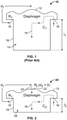
- FIG. 1 illustrates the topology of a typical or conventional moving coil microphone transducer 10, which is shown for comparison to the topology of moving coil microphone transducer 20 designed in accordance with the techniques described herein and shown in FIG. 2 .
- the conventional transducer 10 has an acoustical compliance C l that is defined behind diaphragm 12 in the form of a cavity 14 with a length l l .
- An external acoustic delay d l of the transducer is defined by the distance between a front surface of the diaphragm 12 and a primary tuning port 16, represented by resistance R l , positioned behind or at the rear of the diaphragm 12.
- the port 16 (also referred to as “active diaphragm port” or “rear port”) establishes acoustic communication between the internal cavity volume C l and an external volume surrounding a housing 18 of the transducer 10.
- An acoustic flow (or path) representing the capture of sound waves from the rear of the transducer 10 is illustrated in FIG. 1 by a dotted line 19 entering the acoustic cavity 14 via the primary port 16.
- cavity compliance C l is dependent on primary port resistance R l (also referred to as “diaphragm tuning resistance” or “rear port resistance”) and external acoustic delay d l . Since the typical directional moving coil transducer has a relatively large diaphragm, the distance across the front surface of the diaphragm is also large, thus creating a large external acoustic delay d l . The large external acoustic delay d l is countered by a corresponding internal acoustic delay, which is designed to create a phase shift for cancelling the sound waves approaching from the direction in which the external delay d l is defined.
- the internal acoustic delay is created by the diaphragm tuning resistance R l working in conjunction with the internal cavity volume of the transducer.
- the internal acoustic delay can be made large by setting the internal cavity volume, or cavity compliance C l , to a high value and setting the tuning resistance R l to a low value.
- the diaphragm tuning resistance R l is set to a low value because of the following two characteristics of the transducer. First, given that the diaphragm tuning resistance R l is in series with the diaphragm volume velocity, the resistance R l is typically set to a value equal to the critical damping resistance R d of the diaphragm/coil system in order to critically dampen the diaphragm motion.
- this critical damping resistance R d must be set to an exceedingly low value in order for the moving coil microphone transducer to reproduce the entire audio bandwidth (e.g., 20 hertz (Hz) ⁇ f ⁇ 20 kilohertz (kHz)).
- the diaphragm tuning resistance R l must be decreased down to R d and the cavity compliance C l must be increased accordingly.
- the inner cavity volume of a typical directional, moving coil microphone transducer 10 is relatively large, which tends to increase the overall axial length l l of the transducer 10, as shown in FIG. 1 . This configuration limits the available form factors, and applications, for conventional moving coil microphone transducers.
- FIG. 2 shows a moving coil microphone transducer 20 (also referring to herein as “transducer assembly”) that includes, in addition to the diaphragm 12 and the rear port 16 shown in FIG. 1 , a secondary tuning port 22 located at the front surface of the diaphragm 12, in accordance with embodiments.
- the secondary port 22, represented by resistance R f is substantially parallel to a central axis of the transducer assembly 20 (or the diaphragm 12 included therein) and introduces or provides a second acoustic flow (or path) through the front of the diaphragm 12 and along the central axis, as shown by the second dotted line 24 in FIG. 2 .
- the secondary port 22 is positioned substantially parallel to the primary port 16.
- the ports 22 and 16 form two parallel acoustic branches or paths (i.e. one path through each port) in the transducer 20, and the total series resistance, as seen by the diaphragm 12 of the transducer 20, is equal to R l ⁇ R f , or the parallel equivalent resistance through the two acoustic branches (i.e. R f ⁇ R l / (R f + R l )).
- R d R l ⁇ R f
- the diaphragm tuning resistance R l in transducer 20 can be decoupled from (e.g., need not equal) the critical damping resistance R d , unlike the transducer 10.
- the transducer 20 will still satisfy internal acoustical compliance requirements even if R l is increased beyond R d .
- the resistance R l can be increased to a value larger than the low-valued critical damping resistance R d .
- the diaphragm tuning resistance R 1 of transducer 20 is increased to a high value, which allows for a decrease in cavity compliance C 2 , or a smaller sized internal cavity 26, due to the above-described inverse relationship between diaphragm tuning resistance and internal cavity volume.
- the smaller internal acoustic volume C 2 can be achieved by selecting a smaller length / 2 for the cavity 26 formed behind the diaphragm 12 (e.g., as compared to length l 1 in FIG. 1 ).
- the addition of port 22 can minimize the internal cavity 26, thus reducing the overall form factor of the microphone transducer 20.
- the presence of the secondary port 22 can help lower the cutoff frequency for the microphone transducer 20, since the diaphragm tuning resistance R 1 need not be lowered to the level of the critical damping resistance R d .
- the microphone transducer 20 in order to prevent the decreased compliance C 2 from affecting the bandwidth and directionality (e.g., polar pattern) of the transducer 20, the microphone transducer 20 is configured such that the external acoustic delay d 1 remains unchanged. This can be achieved by selecting a position for the secondary port 22 relative to the diaphragm 12 that does not introduce additional external delay of acoustic waves (i.e. in addition to d 1 ). For example, in FIG.
- the transducer 20 can effectively use volume outside the housing 18 to satisfy internal acoustic compliance requirements, despite the smaller cavity 26. That is, the transducer 20 uses external acoustic volume, in conjunction with the internal acoustic volume 26, to perform microphone operations.
- the techniques described herein provide a moving coil microphone transducer 20 in which the diaphragm tuning resistance R 1 and the internal cavity compliance C 2 can be adjusted without affecting fundamental microphone operation (i.e. bandwidth and directionality requirements).
- the internal cavity 26 is minimized, so that the microphone capsule can have a lower profile, and overall mass, for high sound pressure level (SPL) applications (e.g., guitar amplifiers, percussion, etc.).
- SPL sound pressure level
- the internal cavity volume C 2 can be adjusted to obtain a desired polar pattern (e.g., unidirectional, omnidirectional, cardiod, etc.).
- adjustment of the cavity compliance C 2 parameter may be at least partially achieved by adjusting tuning inertance L 1 and/or external delay d 1 values for the microphone transducer 20.
- the secondary port 22 causes a reduction in the mid-band frequency response, while retaining the low and high frequency response.
- the overall output of the microphone transducer 20 can be more balanced, and for certain applications, more than adequate.
- the decreased sensitivity may not be a problem for high sound pressure level (SPL) applications (e.g., guitar amplifiers, percussion, etc.) or close proximity situations (e.g., vocals, etc.), or when amplification can be used.
- the lower microphone sensitivity can be compensated for through external means, such as, for example, active amplification, optimized magnetic circuit, etc.
- adding the secondary port 22 to the diaphragm 12 does not alter the low impedance characteristic of the transducer 20 at least because the branch resistance R f is placed in parallel with the diaphragm impedance Z m .
- the total equivalent impedance, as seen by the diaphragm 12 is equal to R f ⁇ Z m (i.e. R f ⁇ Z m / (R f + Z m )) , which remains a low value since the equation is dominated by the parallel branch resistance R f .
- the parallel branch resistance R f is selected to be greater than the critical damping resistance R d (i.e. create an over-damp effect), such that the addition of the secondary port 22 to the diaphragm 12 effectively simplifies the acoustical design of a unidirectional moving coil microphone transducer to that of a unidirectional condenser transducer.
- the parallel branch resistance R f is selected to be less than the critical damping resistance R d , for example, in microphone applications where an under damping effect is desired (e.g., in the case of kick drum microphones). In still other embodiments, the parallel branch resistance R f is selected to be equal to the critical damping resistance R d in order to create an isolated transducer for active vibration cancellation (e.g., using accelerometers) that is inherently matched to a non-isolated, active transducer.
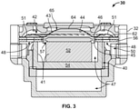
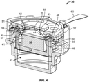
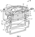
- the transducer 30 includes a housing 32 and a transducer assembly 40 supported within the housing 32 to accept acoustic waves.
- portions of the microphone transducer 30, including the housing 32 and diaphragm 42, are shown as being transparent for illustrative purposes.
- the housing 32 may form all or part of a microphone capsule that encloses the microphone transducer 30 and connects to a larger microphone body 34, which is partially shown in FIG. 5 .
- the transducer assembly 40 is at least topologically similar to the microphone transducer 20 shown in FIG.
- the microphone transducer 30 is configured for unidirectional microphone operation. In other embodiments, the microphone transducer 30 can be configured for other modes of operation (cardioid, omnidirectional, etc.).
- the transducer assembly 40 comprises a magnet assembly 41 and a diaphragm 42 disposed adjacent the magnet assembly 41.
- the diaphragm 42 has a front surface 43 disposed adjacent a front, inner surface of the housing 32 and an opposing rear surface 44 disposed adjacent the magnet assembly 41.
- the front surface 43 of the diaphragm 42 is configured to have acoustic waves impinge thereon.
- the rear surface 44 of the diaphragm 42 is connected or attached to a coil 45 at an attachment point 46. As shown, the coil 45 is suspended from the diaphragm attachment point 46 and extends into the magnet assembly 41 without touching the sides of the magnet assembly 41.
- the coil 45 is situated within the transducer assembly 40 in this manner so as to be capable of interacting with a magnetic field of the magnet assembly 41 in response to acoustic waves impinging on the front surface 43 of the diaphragm 42.
- the transducer assembly 40 defines an internal acoustic space 47 and includes at least one air passage or port 48 for establishing or facilitating acoustic communication between the internal acoustic space 47 and an external cavity 50 located outside the transducer assembly 40.
- the external cavity 50 includes an acoustic space or volume defined between the housing 32 and the transducer assembly 40.
- the external cavity 50 can also include acoustic space located outside the housing 32, or the space surrounding the microphone transducer 30.
- the acoustic port(s) 48 are formed under an outer brim portion 51 of the diaphragm 42, or adjacent to the rear surface 44 of the diaphragm 42.
- the acoustic ports 48 can form all or part of a phase delay network for tuning the directionality of the microphone transducer 30.
- two ports 48 are implemented on either side of the transducer assembly 40.
- the transducer assembly 40 may include a single port 48 on only one side of the transducer assembly 40.
- the magnet assembly 41 includes a centrally disposed magnet 52 having its poles arranged vertically generally along a central vertical axis of the housing 32.
- the magnet assembly 41 also includes an annularly-shaped bottom magnet pole piece 54 that is positioned concentrically outwardly from the magnet 52 and has a magnetic pole that is the same as the magnetic pole of an upper portion of the magnet 52.
- the magnet assembly 41 further includes a top magnet pole piece 56 that is disposed above the central magnet 52, adjacent to upper arms of the bottom magnet pole piece 54.
- the top pole piece 56 has a magnetic pole that is opposite that of the upper portion of the central magnet 52.
- the coil 45 moves with respect to the magnet assembly 41 and its associated magnetic field to generate electrical signals corresponding to the acoustic waves.
- the electrical signals can be transmitted via a coil connection and associated terminal lead, such as, for example, electric lead 60 shown in FIG. 4 or electric lead 61 shown in FIG. 5 .
- the internal acoustic space 47 (e.g., similar to the internal cavity 26 described above and shown in FIG. 2 ) is defined by a space behind the diaphragm 42 or adjacent the rear surface 44, a central space generally associated with the magnet assembly 41, and a rear or back space located below the magnet assembly 41, as shown in FIGS. 3-5 .
- the internal acoustic space 47 also includes a gap 57 formed around the coil 45, or the space between the coil 45 and the magnet 52 and the space between the coil 45 and the top magnet pole piece 56.
- the primary tuning port(s) 48 (e.g., similar to the diaphragm tuning port(s) 16 described above and shown in FIG.
- each primary port 48 is an aperture within the top pole piece 56 (also referred to herein as "top portion") of the magnet assembly 41, so as to create an acoustic flow or path adjacent to the rear surface 44 of the diaphragm 42.
- An acoustic resistance 62 (e.g., similar to the resistance R 1 described above and shown in FIG. 2 ) is disposed between the two pieces of the top pole piece 56, so that the acoustic resistance 62 is encountered by acoustic waves passing through the port(s) 48.
- the acoustic resistance 62 may be a fabric, screen, or other suitable material for creating acoustic flow resistance at the port(s) 48.
- the transducer assembly 40 further includes a secondary port 64 located at the front surface 43 of the diaphragm 42 for creating an acoustic flow or path through the front surface 43.
- the secondary port 64 e.g., similar to the secondary port 22 described above and shown in FIG. 2
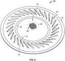
- the secondary port 64 can be formed from, or include, one or more apertures disposed in or through the front surface 43 of the diaphragm 42, as shown in FIG. 6 and described in more detail below.
- FIG. 6 shows an exemplary diaphragm 70 (e.g., similar to diaphragm 42 shown in FIGS. 3-5 ) comprising an exemplary secondary port 72 (e.g., similar to secondary port 64 shown in FIGS. 3-5 ), in accordance with embodiments.
- the secondary port 72 is configured to create a second acoustic flow resistance (e.g., similar to the parallel port resistance R f described above and shown in FIG. 2 ) through the diaphragm 70 and substantially parallel to an acoustic resistance formed below the diaphragm 70 (e.g., similar to acoustic resistance 62 shown in FIGS. 3-5 ).
- a second acoustic flow resistance e.g., similar to the parallel port resistance R f described above and shown in FIG. 2
- the secondary port 72 is located at the center of a dome portion 74 of the diaphragm 70 (e.g., similar to central dome 65 shown in FIGS. 3-5 ), so as to minimize or eliminate an external acoustic delay relative to the diaphragm 70.
- the dome portion 74 is surrounded by a resilient brim 76 (e.g., similar to outer brim portion 51 shown in FIGS. 3-5 ).
- the diaphragm 70 is a single-piece structure, such that the dome portion 74 and the resilient brim 76 are formed from a continuous piece of material.
- An outer edge 78 of the brim 76 may be attached to a top surface of the transducer assembly comprising the diaphragm 70, such as, for example, the transducer assembly 40 shown in FIGS. 3-5 .
- the resilient brim 76 meets or attaches to the dome portion 74 at an inner edge 79.
- a rear surface (e.g., similar to attachment point 46 shown in FIGS. 3-5 ) of the inner edge 79 is attached to a coil (e.g., similar to coil 45 shown in FIGS. 3-5 ) of the transducer assembly.
- tuning port(s) e.g., similar to primary port(s) 48 shown in FIGS. 3-5 ) located underneath the resilient brim 76 between the outer edge 78 and inner edge 79. These acoustic path(s) are substantially parallel to the acoustic path formed through the diaphragm 70 by the secondary port 72.
- the secondary port 72 can be formed from a plurality of apertures 80.
- the apertures 80 are patterned directly into, or formed through, the diaphragm material itself using, for example, laser cut, die cut, or other manufacturing technique capable of piercing or creating holes in the diaphragm 70.
- the patterned portion of the diaphragm 70 serves as the second acoustic resistance (e.g., R f ) for any acoustic waves passing through the secondary port 72.
- the secondary port 72 is created by forming an aperture or hole 82 through the diaphragm 70 and covering the hole 82 with a separate piece of material that includes the plurality of apertures 80 or is otherwise configured to provide the second acoustic resistance (e.g., R f ).
- the diaphragm hole 82 can be formed by cutting out or otherwise removing a portion of the diaphragm 70.
- the acoustic resistance material can be affixed to the diaphragm material surrounding the hole 82 using glue or other appropriate adhesive.
- the acoustic resistance material may be a screen or a piece of fabric that is pre-perforated with the plurality of apertures 80.
- the acoustic resistance material (also referred to herein as a "perforated material”) is a lightweight, low inertance material, so as to avoid mass loading the diaphragm 70 or otherwise altering operation of the microphone transducer due to the additional mass of the acoustic resistance material.
- a second microphone transducer assembly may be added to the microphone transducer 30 to cancel vibrations or otherwise mitigate vibration sensitivity effects in the microphone transducer 30 due to the addition of the secondary port 64.
- the parallel combination of the exposed ports 48 and 64 of the microphone transducer 30 which may be unchanged by the addition of the secondary port 64.
- acoustical excitation occurs through or via the exposed ports 48 and 64 of the microphone transducer 30 and thus, depends on damping through the individual acoustical network paths.
- the addition of secondary port 64 may lower the acoustical response of the microphone transducer 30, as compared to a conventional transducer without a secondary port (e.g., microphone transducer 10 of FIG. 1 ).
- the vibrational response of the microphone transducer 30 may appear to be higher than that of the conventional transducer.
- the vibrational sensitivity of the microphone transducer 30 with secondary port 64 may be greater by a factor of G -1 relative to a conventional microphone transducer with the same acoustical sensitivity.
- moving coil microphone transducers like the transducer 30, are already highly susceptible to structural excitation due to the presence of the coil 45.
- the microphone transducer 30 may require vibrational mitigation strategies to counteract the effects of adding the secondary port 64.
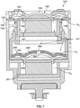
- FIG. 7 shown is one vibration mitigation strategy that uses a second transducer to cancel the vibration generated by the primary transducer. More specifically, FIG. 7 depicts an example microphone transducer 130 comprising a first microphone transducer assembly 140 (also referred to as a "primary transducer") and a second microphone transducer assembly 240 (also referred to as a "cancellation transducer").
- the first microphone transducer assembly 140 can be substantially similar to the microphone transducer assembly 40 shown in FIGs. 3-5 and described above.
- the first transducer 140 can include a magnet assembly 141, a diaphragm 142, and a coil 145 that are substantially similar to the magnet assembly 41, diaphragm 42, and coil 45 of the microphone transducer 30.
- the first transducer 140 can also include primary acoustic ports 148 similar to primary ports 48 of the microphone transducer 30, and a secondary acoustic port 164 through a central dome portion 165 of the diaphragm 142, similar to secondary port 64 of the microphone transducer 30.
- the second transducer assembly 240 may be substantially identical to the first transducer assembly 140.
- the second transducer assembly 240 may have the same structural frequency response as the first transducer 140 and may be oriented along the same excitation axis as, but have opposite polarity than, the first transducer 140.
- the second transducer 240 may also have the same moving coil transducer construction as the first transducer 140.
- the second transducer assembly 240 may include a magnet assembly 241, a diaphragm 242, and a coil 245 that is substantially similar to the magnet assembly 141, diaphragm 142, and coil 145 of the first microphone transducer assembly 140.
- the two microphone transducers 140 and 240 can be incorporated into the same housing 132, so that the transducers 140 and 240 work together as a single microphone capsule with built-in vibration cancellation.
- the output of the secondary transducer 240 must be electrically "subtracted" from the output of the primary transducer 140, with appropriate considerations being made for total microphone electrical output impedance. In embodiments, this can be achieved using one of two mechanical/acoustical implementations for constructing a microphone using two transducers.
- a first exemplary implementation for placing two transducers within one microphone capsule involves completely isolating an internal acoustical domain C 2 of the first transducer 140 from an internal acoustical domain C 3 of the second transducer 240, such that the two transducers 140 and 240 are completely independent.
- This implementation may be optimal under certain orientation constraints, but does not allow minimization of the microphone capsule size. Thus, the first implementation may not be preferred when trying to achieve a smaller form factor.
- FIG. 7 illustrates a second exemplary implementation, wherein the second microphone transducer assembly 240 is placed within an internal acoustical cavity 147 (or acoustical domain C 2 ) of the first microphone transducer assembly 140.
- the acoustical domain C 3 of the second transducer 240 is shared with the acoustical domain C 2 of the first transducer 140.
- the cavities C 2 and C 3 can be coupled through a port 290 having an acoustic resistance R 3 , so that the second transducer 240 can operate within the primary tuning volume C 2 of the first transducer 140.
- the cancellation transducer 240 can be encased completely within the primary transducer 140, such that no extra space is required to accommodate the second transducer assembly 240.
- the housing 132 can be substantially similar in size and shape to the housing 32 of the microphone transducer 30.
- the second transducer 240 is coupled to the structural disturbances and internal acoustical disturbances of the first transducer 140, but may be isolated from the external acoustic disturbances experienced by the first transducer 140. This is because the internal acoustical domain C 2 of the primary transducer 140 is partially isolated from the external acoustical disturbances due to an acoustic resistance R 1 through the primary ports 148 of the first transducer 140. At the same time, cavity impedance over the intended bandwidth is such that acoustic pressure changes uniformly within the cavity C 2 .
- the cavity pressure fluctuation of C 2 does not excite the diaphragm 242 of the cancellation transducer 240 (or if it does, it can be accounted for in the resulting frequency response using known techniques).
- cavity segmentation, ported through acoustical resistance can be used if additional isolation is needed, but depending on the resistance through the zero delay port 164, the resistance R 1 through the primary ports 148 may be large enough for isolation.
- R d critical damping resistance
- the second transducer 240 may be configured to have the same R d parameter as the primary transducer 140. This may be achieved, at least in part, by using the techniques described above to create a secondary port 264 through the diaphragm 242 of the second transducer 240, similar to the secondary port 164 of the first transducer 140.
- the secondary port 264 may be formed by either creating a plurality of holes within the center of a central dome portion 265 of the diaphragm 242 or by placing a separate screen or cloth over a hole through the central dome portion 265 (see, e.g., FIG. 6 ).
- the second transducer 240 may be configured such that the secondary port 164 represents the sole acoustical path from the front of the diaphragm 242 to the back of the diaphragm 242, thus making the total series resistance for the second transducer 240 equal to the acoustic resistance R f2 through the secondary port 264.
- the illustrated implementation can provide vibration cancellation without sacrificing the smaller microphone capsule size of the microphone transducer 130.
- the microphone transducer 130 can be configured to obtain first order directionality while also accounting for a pressure response from the secondary transducer 240 within the combined electrical signal output by the microphone transducer 130.
- the second transducer 240 is effectively bypassed by the resistance R f2 through the secondary port 264, the second transducer 240 may output a low-level pressure response that, unless accounted for, can affect the frequency response of the first transducer 140, or at the very least, create a "noise floor" that acts as a minimum level of rejection for the polar pattern of the microphone.
- One technique for addressing this issue is to modify the polar response of the primary transducer 140 by intentionally "de-tuning" the polar response of the primary transducer 140 to match the pressure response of the secondary transducer 240, so that when the response signals are subtracted, the resulting output signal is the desired polar response.
- the individual response of the primary transducer 140 can be pushed towards omnidirectional, as compared to the desired polar response, and the secondary transducer 240 can have a pressure response that is proportional to the cavity pressure within the cavity in front of the diaphragm, or C f , at low frequencies. At higher frequencies, the acoustical response may be unaffected by the second transducer 240 because the pressure response rolls off in amplitude.
Landscapes
- Engineering & Computer Science (AREA)
- Physics & Mathematics (AREA)
- Acoustics & Sound (AREA)
- Signal Processing (AREA)
- Health & Medical Sciences (AREA)
- Otolaryngology (AREA)
- Multimedia (AREA)
- Mechanical Engineering (AREA)
- Audible-Bandwidth Dynamoelectric Transducers Other Than Pickups (AREA)
- Obtaining Desirable Characteristics In Audible-Bandwidth Transducers (AREA)
- Details Of Audible-Bandwidth Transducers (AREA)
Claims (11)
- Mikrofonwandler (30), umfassend:ein Gehäuse (32);eine erste Wandleranordnung (40), die innerhalb des Gehäuses gelagert ist und einen internen akustischen Raum (47) definiert, wobei die erste Wandleranordnung eine Magnetanordnung (41), eine Membran (42), die benachbart zu der Magnetanordnung angeordnet ist und eine vordere Fläche (43) und eine hintere Fläche (44) aufweist, und eine Spule (45), die an der hinteren Fläche der Membran angebracht ist und in der Lage ist, sich in Reaktion auf akustische Wellen, die auf die vordere Fläche auftreffen, relativ zu der Magnetanordnung zu bewegen, beinhaltet;eine primäre Durchlassöffnung (48), die akustische Kommunikation zwischen dem internen akustischen Raum und einem externen Hohlraum (50), der sich außerhalb der ersten Wandleranordnung und zumindest teilweise innerhalb des Gehäuses befindet, herstellt;dadurch gekennzeichnet, dass der Mikrofonwandler ferner umfasst:eine sekundäre Durchlassöffnung (64), die sich an der vorderen Fläche der Membran befindet,wobei die sekundäre Durchlassöffnung im Wesentlichen parallel zu der primären Durchlassöffnung angeordnet ist.
- Mikrofonwandler nach Anspruch 1, wobei sich die sekundäre Durchlassöffnung in einer Mitte der vorderen Fläche der Membran befindet, so dass eine externe akustische Verzögerung, die mit der sekundären Durchlassöffnung assoziiert ist, im Wesentlichen gleich Null ist.
- Mikrofonwandler nach Anspruch 1, wobei die sekundäre Durchlassöffnung aus mindestens einem Durchlass gebildet ist, der durch die Membran verläuft.
- Mikrofonwandler nach Anspruch 1, wobei die sekundäre Durchlassöffnung aus einer Vielzahl von Durchlässen gebildet ist, die in das Membranmaterial strukturiert sind.
- Mikrofonwandler nach Anspruch 3, wobei die sekundäre Durchlassöffnung aus einem perforierten Material gebildet ist, das den mindestens einen Durchlass der Membran abdeckt.
- Mikrofonwandler nach Anspruch 1, wobei sich die primäre Durchlassöffnung unter einem elastischen Rand der Membran befindet.
- Mikrofonwandler nach Anspruch 6, wobei die primäre Durchlassöffnung ein Durchlass ist, der innerhalb eines oberen Teils der Magnetanordnung angeordnet ist.
- Mikrofonwandler nach Anspruch 1, wobei ein akustischer Widerstand, der mit der primären Durchlassöffnung assoziiert ist, größer als ein kritischer Dämpfungswiderstand der Membran ist.
- Mikrofonwandler nach Anspruch 1, der ferner eine zweite Wandleranordnung umfasst, die innerhalb des internen akustischen Raums der ersten Wandleranordnung angeordnet ist.
- Mikrofonwandler nach Anspruch 9, wobei die zweite Wandleranordnung eine zweite Magnetanordnung, eine zweite Membran, die benachbart zu der zweiten Magnetanordnung angeordnet ist, eine zweite Spule, die an einer hinteren Fläche der zweiten Membran angebracht ist und in der Lage ist, sich in Reaktion auf akustische Wellen, die auf eine vordere Fläche der zweiten Membran auftreffen, relativ zu der zweiten Magnetanordnung zu bewegen, und eine zweite sekundäre Durchlassöffnung, die sich an der vorderen Fläche der zweiten Membran befindet, beinhaltet.
- Mikrofon, das den Mikrofonwandler nach Anspruch 1 umfasst, wobei:das Gehäuse ein Mikrofonkörper ist; undder externe Hohlraum ein externes akustisches Volumen ist, das sich außerhalb der ersten Wandleranordnung befindet.
Applications Claiming Priority (2)
| Application Number | Priority Date | Filing Date | Title |
|---|---|---|---|
| US15/653,217 US10542337B2 (en) | 2017-07-18 | 2017-07-18 | Moving coil microphone transducer with secondary port |
| PCT/US2018/042727 WO2019018549A1 (en) | 2017-07-18 | 2018-07-18 | MOBILE COIL MICROPHONE TRANSDUCER WITH SECONDARY ORIFICE |
Publications (2)
| Publication Number | Publication Date |
|---|---|
| EP3656136A1 EP3656136A1 (de) | 2020-05-27 |
| EP3656136B1 true EP3656136B1 (de) | 2022-01-19 |
Family
ID=63104123
Family Applications (1)
| Application Number | Title | Priority Date | Filing Date |
|---|---|---|---|
| EP18750030.1A Active EP3656136B1 (de) | 2017-07-18 | 2018-07-18 | Mikrofonumwandler mit beweglicher spule mit sekundäranschluss |
Country Status (7)
| Country | Link |
|---|---|
| US (3) | US10542337B2 (de) |
| EP (1) | EP3656136B1 (de) |
| JP (1) | JP7150813B2 (de) |
| KR (1) | KR102552384B1 (de) |
| CN (2) | CN110999322B (de) |
| TW (1) | TWI771455B (de) |
| WO (1) | WO2019018549A1 (de) |
Families Citing this family (7)
| Publication number | Priority date | Publication date | Assignee | Title |
|---|---|---|---|---|
| US10542337B2 (en) * | 2017-07-18 | 2020-01-21 | Shure Acquisition Holdings, Inc. | Moving coil microphone transducer with secondary port |
| CN213818153U (zh) * | 2019-12-30 | 2021-07-27 | 楼氏电子(苏州)有限公司 | 微机电系统换能器和麦克风组件 |
| USD1034193S1 (en) * | 2020-01-27 | 2024-07-09 | Tekni-Plex, Inc. | Packaging tray |
| CN112278516A (zh) * | 2020-10-27 | 2021-01-29 | 杨晴晴 | 一种无接触定量取茶密封茶叶罐 |
| TWI779407B (zh) * | 2020-11-24 | 2022-10-01 | 美律實業股份有限公司 | 電子裝置 |
| CN112954557B (zh) * | 2021-03-01 | 2023-03-28 | 潍坊歌尔微电子有限公司 | 麦克风和电子设备 |
| EP4231662A1 (de) * | 2022-02-17 | 2023-08-23 | Sonova AG | Hörgerät mit aktiver geräuschkontrolle |
Family Cites Families (38)
| Publication number | Priority date | Publication date | Assignee | Title |
|---|---|---|---|---|
| US3132713A (en) * | 1961-05-25 | 1964-05-12 | Shure Bros | Microphone diaphragm |
| NL291745A (de) * | 1962-04-27 | |||
| AT256951B (de) | 1963-11-23 | 1967-09-11 | Elektroakusztikai Gyar | Dynamisches Schwingspulenmikrophon |
| AT274916B (de) | 1966-02-14 | 1969-10-10 | Elektroakusztikai Gyar | Dynamisches Mikrophon |
| JPS5618420B2 (de) | 1972-10-09 | 1981-04-28 | ||
| US3940575A (en) * | 1975-03-03 | 1976-02-24 | Cbs Inc. | Directional microphone |
| US3989905A (en) | 1975-12-15 | 1976-11-02 | Shure Brothers Inc. | Microphone |
| JPS5315691A (en) | 1976-07-29 | 1978-02-13 | Toyoda Mach Works Ltd | Method of making resinoid grinding stone |
| JPS5388718A (en) * | 1976-12-15 | 1978-08-04 | Matsushita Electric Ind Co Ltd | Sealed head phone |
| JPS5618420A (en) | 1979-07-23 | 1981-02-21 | Fujitsu Ltd | Manufacture of semiconductor device |
| JPS5651070A (en) | 1979-09-29 | 1981-05-08 | Toshiba Corp | Magnetic tape device |
| US4410770A (en) * | 1981-06-08 | 1983-10-18 | Electro-Voice, Incorporated | Directional microphone |
| JPS6150398A (ja) | 1984-08-20 | 1986-03-12 | 日立入間電子株式会社 | 電子部品搬送体 |
| JPS6150398U (de) * | 1984-09-07 | 1986-04-04 | ||
| JPH0450718Y2 (de) * | 1986-02-28 | 1992-11-30 | ||
| DE3929266C1 (de) | 1989-09-02 | 1991-01-03 | Mercedes-Benz Aktiengesellschaft, 7000 Stuttgart, De | |
| JPH03130700U (de) * | 1990-04-10 | 1991-12-27 | ||
| US5226076A (en) * | 1993-02-28 | 1993-07-06 | At&T Bell Laboratories | Directional microphone assembly |
| JP3158850B2 (ja) | 1994-03-14 | 2001-04-23 | ソニー株式会社 | マイクロフォン |
| JP4106119B2 (ja) * | 1997-12-26 | 2008-06-25 | 株式会社オーディオテクニカ | ダイナミックマイクロホン |
| AU2005234549B2 (en) | 2004-04-16 | 2009-10-29 | New Transducers Limited | Acoustic device and method of making acoustic device |
| KR100715003B1 (ko) * | 2005-02-23 | 2007-05-09 | 주식회사 벨류텔 | 음향 및 진동발생용 마이크로스피커 |
| JP5081604B2 (ja) * | 2007-12-18 | 2012-11-28 | 株式会社オーディオテクニカ | ダイナミックマイクロホン |
| JP5434798B2 (ja) * | 2009-12-25 | 2014-03-05 | 船井電機株式会社 | マイクロホンユニット、及び、それを備えた音声入力装置 |
| JP5527615B2 (ja) | 2010-12-02 | 2014-06-18 | 株式会社オーディオテクニカ | ダイナミックマイクロホン |
| JP5651070B2 (ja) | 2011-05-13 | 2015-01-07 | 株式会社オーディオテクニカ | ダイナミックマイクロホンユニット |
| JP5618420B2 (ja) | 2011-06-30 | 2014-11-05 | 株式会社オーディオテクニカ | 電気音響変換器 |
| JP5665697B2 (ja) | 2011-09-01 | 2015-02-04 | 株式会社オーディオテクニカ | ダイナミックマイクロホンユニットおよびダイナミックマイクロホン |
| JP5650079B2 (ja) | 2011-09-02 | 2015-01-07 | 株式会社オーディオテクニカ | ダイナミックマイクロホンユニットおよびダイナミックマイクロホン |
| US8818009B2 (en) * | 2012-10-23 | 2014-08-26 | Shure Acquisition Holdings, Inc. | Dual diaphragm dynamic microphone transducer |
| CN203289638U (zh) * | 2013-03-20 | 2013-11-13 | 吴宗汉 | 一种非磁钢系统受话器和扬声器 |
| JP6206906B2 (ja) | 2013-06-27 | 2017-10-04 | 株式会社オーディオテクニカ | ダイナミックマイクロホンユニットおよびダイナミックマイクロホン |
| KR101518562B1 (ko) | 2013-07-11 | 2015-05-07 | 주식회사 포스코 | 레이저를 이용한 도금 원소 분석 시스템 및 그 방법 |
| US9510074B2 (en) | 2014-07-07 | 2016-11-29 | Apple Inc. | Grating only optical microphone |
| US20160037263A1 (en) * | 2014-08-04 | 2016-02-04 | Knowles Electronics, Llc | Electrostatic microphone with reduced acoustic noise |
| JP6332862B2 (ja) | 2014-10-17 | 2018-05-30 | 株式会社オーディオテクニカ | ダイナミックマイクロホンユニットおよびダイナミックマイクロホン |
| CN107409259B (zh) * | 2015-04-21 | 2020-05-12 | 东京音响株式会社 | 电子音响变换装置 |
| US10542337B2 (en) * | 2017-07-18 | 2020-01-21 | Shure Acquisition Holdings, Inc. | Moving coil microphone transducer with secondary port |
-
2017
- 2017-07-18 US US15/653,217 patent/US10542337B2/en active Active
-
2018
- 2018-07-18 TW TW107124832A patent/TWI771455B/zh active
- 2018-07-18 WO PCT/US2018/042727 patent/WO2019018549A1/en not_active Ceased
- 2018-07-18 CN CN201880054693.9A patent/CN110999322B/zh active Active
- 2018-07-18 EP EP18750030.1A patent/EP3656136B1/de active Active
- 2018-07-18 CN CN202111150995.6A patent/CN113873373B/zh active Active
- 2018-07-18 JP JP2020502275A patent/JP7150813B2/ja active Active
- 2018-07-18 KR KR1020207004299A patent/KR102552384B1/ko active Active
-
2020
- 2020-01-17 US US16/746,044 patent/US11451891B2/en active Active
-
2022
- 2022-08-15 US US17/819,682 patent/US12495231B2/en active Active
Also Published As
| Publication number | Publication date |
|---|---|
| EP3656136A1 (de) | 2020-05-27 |
| TW201909655A (zh) | 2019-03-01 |
| CN110999322A (zh) | 2020-04-10 |
| US20190028786A1 (en) | 2019-01-24 |
| US20200260165A1 (en) | 2020-08-13 |
| TWI771455B (zh) | 2022-07-21 |
| JP7150813B2 (ja) | 2022-10-11 |
| KR102552384B1 (ko) | 2023-07-05 |
| CN113873373B (zh) | 2025-01-10 |
| US12495231B2 (en) | 2025-12-09 |
| KR20200033884A (ko) | 2020-03-30 |
| JP2020527906A (ja) | 2020-09-10 |
| WO2019018549A1 (en) | 2019-01-24 |
| CN113873373A (zh) | 2021-12-31 |
| US20220394364A1 (en) | 2022-12-08 |
| US10542337B2 (en) | 2020-01-21 |
| US11451891B2 (en) | 2022-09-20 |
| CN110999322B (zh) | 2021-10-22 |
Similar Documents
| Publication | Publication Date | Title |
|---|---|---|
| US12495231B2 (en) | Microphone with first and second transducer assemblies | |
| CN110603816B (zh) | 具有电磁扬声器和微型扬声器的扬声器单元 | |
| CN102396243B (zh) | 扩音器 | |
| CN112653964B (zh) | 一种耳机系统 | |
| US7072482B2 (en) | Microphone with improved sound inlet port | |
| US11463816B2 (en) | Directional MEMS microphone with correction circuitry | |
| TWI695628B (zh) | 電聲轉換器 | |
| CN107113493B (zh) | 微型扬声器声阻组件 | |
| WO2022227629A1 (zh) | 入耳式耳机 | |
| US20130322656A1 (en) | Loudspeaker system | |
| EP2912857B1 (de) | Dynamisches doppelmembranmikrofon | |
| WO2022143209A1 (zh) | 发声单体和耳机 | |
| WO2020026944A1 (ja) | 音響出力装置 |
Legal Events
| Date | Code | Title | Description |
|---|---|---|---|
| STAA | Information on the status of an ep patent application or granted ep patent |
Free format text: STATUS: UNKNOWN |
|
| STAA | Information on the status of an ep patent application or granted ep patent |
Free format text: STATUS: THE INTERNATIONAL PUBLICATION HAS BEEN MADE |
|
| PUAI | Public reference made under article 153(3) epc to a published international application that has entered the european phase |
Free format text: ORIGINAL CODE: 0009012 |
|
| STAA | Information on the status of an ep patent application or granted ep patent |
Free format text: STATUS: REQUEST FOR EXAMINATION WAS MADE |
|
| 17P | Request for examination filed |
Effective date: 20200117 |
|
| AK | Designated contracting states |
Kind code of ref document: A1 Designated state(s): AL AT BE BG CH CY CZ DE DK EE ES FI FR GB GR HR HU IE IS IT LI LT LU LV MC MK MT NL NO PL PT RO RS SE SI SK SM TR |
|
| AX | Request for extension of the european patent |
Extension state: BA ME |
|
| DAV | Request for validation of the european patent (deleted) | ||
| DAX | Request for extension of the european patent (deleted) | ||
| GRAP | Despatch of communication of intention to grant a patent |
Free format text: ORIGINAL CODE: EPIDOSNIGR1 |
|
| STAA | Information on the status of an ep patent application or granted ep patent |
Free format text: STATUS: GRANT OF PATENT IS INTENDED |
|
| INTG | Intention to grant announced |
Effective date: 20210305 |
|
| GRAJ | Information related to disapproval of communication of intention to grant by the applicant or resumption of examination proceedings by the epo deleted |
Free format text: ORIGINAL CODE: EPIDOSDIGR1 |
|
| STAA | Information on the status of an ep patent application or granted ep patent |
Free format text: STATUS: REQUEST FOR EXAMINATION WAS MADE |
|
| GRAP | Despatch of communication of intention to grant a patent |
Free format text: ORIGINAL CODE: EPIDOSNIGR1 |
|
| STAA | Information on the status of an ep patent application or granted ep patent |
Free format text: STATUS: GRANT OF PATENT IS INTENDED |
|
| INTC | Intention to grant announced (deleted) | ||
| INTG | Intention to grant announced |
Effective date: 20210809 |
|
| GRAS | Grant fee paid |
Free format text: ORIGINAL CODE: EPIDOSNIGR3 |
|
| GRAA | (expected) grant |
Free format text: ORIGINAL CODE: 0009210 |
|
| STAA | Information on the status of an ep patent application or granted ep patent |
Free format text: STATUS: THE PATENT HAS BEEN GRANTED |
|
| AK | Designated contracting states |
Kind code of ref document: B1 Designated state(s): AL AT BE BG CH CY CZ DE DK EE ES FI FR GB GR HR HU IE IS IT LI LT LU LV MC MK MT NL NO PL PT RO RS SE SI SK SM TR |
|
| REG | Reference to a national code |
Ref country code: GB Ref legal event code: FG4D |
|
| REG | Reference to a national code |
Ref country code: CH Ref legal event code: EP |
|
| REG | Reference to a national code |
Ref country code: DE Ref legal event code: R096 Ref document number: 602018029793 Country of ref document: DE |
|
| REG | Reference to a national code |
Ref country code: AT Ref legal event code: REF Ref document number: 1464464 Country of ref document: AT Kind code of ref document: T Effective date: 20220215 |
|
| REG | Reference to a national code |
Ref country code: IE Ref legal event code: FG4D |
|
| REG | Reference to a national code |
Ref country code: LT Ref legal event code: MG9D |
|
| REG | Reference to a national code |
Ref country code: NL Ref legal event code: MP Effective date: 20220119 |
|
| REG | Reference to a national code |
Ref country code: AT Ref legal event code: MK05 Ref document number: 1464464 Country of ref document: AT Kind code of ref document: T Effective date: 20220119 |
|
| PG25 | Lapsed in a contracting state [announced via postgrant information from national office to epo] |
Ref country code: NL Free format text: LAPSE BECAUSE OF FAILURE TO SUBMIT A TRANSLATION OF THE DESCRIPTION OR TO PAY THE FEE WITHIN THE PRESCRIBED TIME-LIMIT Effective date: 20220119 |
|
| PG25 | Lapsed in a contracting state [announced via postgrant information from national office to epo] |
Ref country code: SE Free format text: LAPSE BECAUSE OF FAILURE TO SUBMIT A TRANSLATION OF THE DESCRIPTION OR TO PAY THE FEE WITHIN THE PRESCRIBED TIME-LIMIT Effective date: 20220119 Ref country code: RS Free format text: LAPSE BECAUSE OF FAILURE TO SUBMIT A TRANSLATION OF THE DESCRIPTION OR TO PAY THE FEE WITHIN THE PRESCRIBED TIME-LIMIT Effective date: 20220119 Ref country code: PT Free format text: LAPSE BECAUSE OF FAILURE TO SUBMIT A TRANSLATION OF THE DESCRIPTION OR TO PAY THE FEE WITHIN THE PRESCRIBED TIME-LIMIT Effective date: 20220519 Ref country code: NO Free format text: LAPSE BECAUSE OF FAILURE TO SUBMIT A TRANSLATION OF THE DESCRIPTION OR TO PAY THE FEE WITHIN THE PRESCRIBED TIME-LIMIT Effective date: 20220419 Ref country code: LT Free format text: LAPSE BECAUSE OF FAILURE TO SUBMIT A TRANSLATION OF THE DESCRIPTION OR TO PAY THE FEE WITHIN THE PRESCRIBED TIME-LIMIT Effective date: 20220119 Ref country code: HR Free format text: LAPSE BECAUSE OF FAILURE TO SUBMIT A TRANSLATION OF THE DESCRIPTION OR TO PAY THE FEE WITHIN THE PRESCRIBED TIME-LIMIT Effective date: 20220119 Ref country code: ES Free format text: LAPSE BECAUSE OF FAILURE TO SUBMIT A TRANSLATION OF THE DESCRIPTION OR TO PAY THE FEE WITHIN THE PRESCRIBED TIME-LIMIT Effective date: 20220119 Ref country code: BG Free format text: LAPSE BECAUSE OF FAILURE TO SUBMIT A TRANSLATION OF THE DESCRIPTION OR TO PAY THE FEE WITHIN THE PRESCRIBED TIME-LIMIT Effective date: 20220419 |
|
| PG25 | Lapsed in a contracting state [announced via postgrant information from national office to epo] |
Ref country code: PL Free format text: LAPSE BECAUSE OF FAILURE TO SUBMIT A TRANSLATION OF THE DESCRIPTION OR TO PAY THE FEE WITHIN THE PRESCRIBED TIME-LIMIT Effective date: 20220119 Ref country code: LV Free format text: LAPSE BECAUSE OF FAILURE TO SUBMIT A TRANSLATION OF THE DESCRIPTION OR TO PAY THE FEE WITHIN THE PRESCRIBED TIME-LIMIT Effective date: 20220119 Ref country code: GR Free format text: LAPSE BECAUSE OF FAILURE TO SUBMIT A TRANSLATION OF THE DESCRIPTION OR TO PAY THE FEE WITHIN THE PRESCRIBED TIME-LIMIT Effective date: 20220420 Ref country code: FI Free format text: LAPSE BECAUSE OF FAILURE TO SUBMIT A TRANSLATION OF THE DESCRIPTION OR TO PAY THE FEE WITHIN THE PRESCRIBED TIME-LIMIT Effective date: 20220119 Ref country code: AT Free format text: LAPSE BECAUSE OF FAILURE TO SUBMIT A TRANSLATION OF THE DESCRIPTION OR TO PAY THE FEE WITHIN THE PRESCRIBED TIME-LIMIT Effective date: 20220119 |
|
| PG25 | Lapsed in a contracting state [announced via postgrant information from national office to epo] |
Ref country code: IS Free format text: LAPSE BECAUSE OF FAILURE TO SUBMIT A TRANSLATION OF THE DESCRIPTION OR TO PAY THE FEE WITHIN THE PRESCRIBED TIME-LIMIT Effective date: 20220519 |
|
| REG | Reference to a national code |
Ref country code: DE Ref legal event code: R097 Ref document number: 602018029793 Country of ref document: DE |
|
| PG25 | Lapsed in a contracting state [announced via postgrant information from national office to epo] |
Ref country code: SM Free format text: LAPSE BECAUSE OF FAILURE TO SUBMIT A TRANSLATION OF THE DESCRIPTION OR TO PAY THE FEE WITHIN THE PRESCRIBED TIME-LIMIT Effective date: 20220119 Ref country code: SK Free format text: LAPSE BECAUSE OF FAILURE TO SUBMIT A TRANSLATION OF THE DESCRIPTION OR TO PAY THE FEE WITHIN THE PRESCRIBED TIME-LIMIT Effective date: 20220119 Ref country code: RO Free format text: LAPSE BECAUSE OF FAILURE TO SUBMIT A TRANSLATION OF THE DESCRIPTION OR TO PAY THE FEE WITHIN THE PRESCRIBED TIME-LIMIT Effective date: 20220119 Ref country code: EE Free format text: LAPSE BECAUSE OF FAILURE TO SUBMIT A TRANSLATION OF THE DESCRIPTION OR TO PAY THE FEE WITHIN THE PRESCRIBED TIME-LIMIT Effective date: 20220119 Ref country code: DK Free format text: LAPSE BECAUSE OF FAILURE TO SUBMIT A TRANSLATION OF THE DESCRIPTION OR TO PAY THE FEE WITHIN THE PRESCRIBED TIME-LIMIT Effective date: 20220119 Ref country code: CZ Free format text: LAPSE BECAUSE OF FAILURE TO SUBMIT A TRANSLATION OF THE DESCRIPTION OR TO PAY THE FEE WITHIN THE PRESCRIBED TIME-LIMIT Effective date: 20220119 |
|
| PLBE | No opposition filed within time limit |
Free format text: ORIGINAL CODE: 0009261 |
|
| STAA | Information on the status of an ep patent application or granted ep patent |
Free format text: STATUS: NO OPPOSITION FILED WITHIN TIME LIMIT |
|
| PG25 | Lapsed in a contracting state [announced via postgrant information from national office to epo] |
Ref country code: AL Free format text: LAPSE BECAUSE OF FAILURE TO SUBMIT A TRANSLATION OF THE DESCRIPTION OR TO PAY THE FEE WITHIN THE PRESCRIBED TIME-LIMIT Effective date: 20220119 |
|
| 26N | No opposition filed |
Effective date: 20221020 |
|
| PG25 | Lapsed in a contracting state [announced via postgrant information from national office to epo] |
Ref country code: SI Free format text: LAPSE BECAUSE OF FAILURE TO SUBMIT A TRANSLATION OF THE DESCRIPTION OR TO PAY THE FEE WITHIN THE PRESCRIBED TIME-LIMIT Effective date: 20220119 Ref country code: MC Free format text: LAPSE BECAUSE OF FAILURE TO SUBMIT A TRANSLATION OF THE DESCRIPTION OR TO PAY THE FEE WITHIN THE PRESCRIBED TIME-LIMIT Effective date: 20220119 |
|
| REG | Reference to a national code |
Ref country code: CH Ref legal event code: PL |
|
| GBPC | Gb: european patent ceased through non-payment of renewal fee |
Effective date: 20220718 |
|
| REG | Reference to a national code |
Ref country code: BE Ref legal event code: MM Effective date: 20220731 |
|
| PG25 | Lapsed in a contracting state [announced via postgrant information from national office to epo] |
Ref country code: LU Free format text: LAPSE BECAUSE OF NON-PAYMENT OF DUE FEES Effective date: 20220718 Ref country code: LI Free format text: LAPSE BECAUSE OF NON-PAYMENT OF DUE FEES Effective date: 20220731 Ref country code: FR Free format text: LAPSE BECAUSE OF NON-PAYMENT OF DUE FEES Effective date: 20220731 Ref country code: CH Free format text: LAPSE BECAUSE OF NON-PAYMENT OF DUE FEES Effective date: 20220731 |
|
| PG25 | Lapsed in a contracting state [announced via postgrant information from national office to epo] |
Ref country code: GB Free format text: LAPSE BECAUSE OF NON-PAYMENT OF DUE FEES Effective date: 20220718 Ref country code: BE Free format text: LAPSE BECAUSE OF NON-PAYMENT OF DUE FEES Effective date: 20220731 |
|
| P01 | Opt-out of the competence of the unified patent court (upc) registered |
Effective date: 20230519 |
|
| PG25 | Lapsed in a contracting state [announced via postgrant information from national office to epo] |
Ref country code: IT Free format text: LAPSE BECAUSE OF FAILURE TO SUBMIT A TRANSLATION OF THE DESCRIPTION OR TO PAY THE FEE WITHIN THE PRESCRIBED TIME-LIMIT Effective date: 20220119 Ref country code: IE Free format text: LAPSE BECAUSE OF NON-PAYMENT OF DUE FEES Effective date: 20220718 |
|
| PG25 | Lapsed in a contracting state [announced via postgrant information from national office to epo] |
Ref country code: MK Free format text: LAPSE BECAUSE OF FAILURE TO SUBMIT A TRANSLATION OF THE DESCRIPTION OR TO PAY THE FEE WITHIN THE PRESCRIBED TIME-LIMIT Effective date: 20220119 Ref country code: CY Free format text: LAPSE BECAUSE OF FAILURE TO SUBMIT A TRANSLATION OF THE DESCRIPTION OR TO PAY THE FEE WITHIN THE PRESCRIBED TIME-LIMIT Effective date: 20220119 |
|
| PG25 | Lapsed in a contracting state [announced via postgrant information from national office to epo] |
Ref country code: HU Free format text: LAPSE BECAUSE OF FAILURE TO SUBMIT A TRANSLATION OF THE DESCRIPTION OR TO PAY THE FEE WITHIN THE PRESCRIBED TIME-LIMIT; INVALID AB INITIO Effective date: 20180718 |
|
| PG25 | Lapsed in a contracting state [announced via postgrant information from national office to epo] |
Ref country code: MT Free format text: LAPSE BECAUSE OF FAILURE TO SUBMIT A TRANSLATION OF THE DESCRIPTION OR TO PAY THE FEE WITHIN THE PRESCRIBED TIME-LIMIT Effective date: 20220119 |
|
| PGFP | Annual fee paid to national office [announced via postgrant information from national office to epo] |
Ref country code: DE Payment date: 20250521 Year of fee payment: 8 |
|
| PG25 | Lapsed in a contracting state [announced via postgrant information from national office to epo] |
Ref country code: TR Free format text: LAPSE BECAUSE OF FAILURE TO SUBMIT A TRANSLATION OF THE DESCRIPTION OR TO PAY THE FEE WITHIN THE PRESCRIBED TIME-LIMIT Effective date: 20220119 |