EP3655920B1 - Procédé et dispositif pour l'évaluation de sections d'images pour un calcul de correspondance - Google Patents
Procédé et dispositif pour l'évaluation de sections d'images pour un calcul de correspondance Download PDFInfo
- Publication number
- EP3655920B1 EP3655920B1 EP18731048.7A EP18731048A EP3655920B1 EP 3655920 B1 EP3655920 B1 EP 3655920B1 EP 18731048 A EP18731048 A EP 18731048A EP 3655920 B1 EP3655920 B1 EP 3655920B1
- Authority
- EP
- European Patent Office
- Prior art keywords
- image
- noise
- image sensor
- signal
- resulting
- Prior art date
- Legal status (The legal status is an assumption and is not a legal conclusion. Google has not performed a legal analysis and makes no representation as to the accuracy of the status listed.)
- Active
Links
- 238000000034 method Methods 0.000 title claims description 28
- 238000004364 calculation method Methods 0.000 title description 3
- 238000011156 evaluation Methods 0.000 claims description 112
- 230000006641 stabilisation Effects 0.000 claims description 14
- 238000011105 stabilization Methods 0.000 claims description 14
- 238000007906 compression Methods 0.000 claims description 9
- 230000006835 compression Effects 0.000 claims description 9
- 230000002123 temporal effect Effects 0.000 claims description 5
- 238000001914 filtration Methods 0.000 claims description 4
- 230000015572 biosynthetic process Effects 0.000 description 26
- 238000012545 processing Methods 0.000 description 16
- 238000013507 mapping Methods 0.000 description 15
- 230000033001 locomotion Effects 0.000 description 13
- 238000009499 grossing Methods 0.000 description 7
- 230000008569 process Effects 0.000 description 5
- 239000010426 asphalt Substances 0.000 description 4
- 230000005540 biological transmission Effects 0.000 description 4
- 238000010586 diagram Methods 0.000 description 3
- 230000003287 optical effect Effects 0.000 description 3
- 238000013139 quantization Methods 0.000 description 3
- 230000006978 adaptation Effects 0.000 description 2
- 230000003321 amplification Effects 0.000 description 2
- 230000001419 dependent effect Effects 0.000 description 2
- 238000005259 measurement Methods 0.000 description 2
- 238000003199 nucleic acid amplification method Methods 0.000 description 2
- 238000003860 storage Methods 0.000 description 2
- 239000000654 additive Substances 0.000 description 1
- 230000000996 additive effect Effects 0.000 description 1
- 238000013459 approach Methods 0.000 description 1
- 230000008901 benefit Effects 0.000 description 1
- 230000003139 buffering effect Effects 0.000 description 1
- 230000008859 change Effects 0.000 description 1
- 238000013144 data compression Methods 0.000 description 1
- 238000009826 distribution Methods 0.000 description 1
- 230000000694 effects Effects 0.000 description 1
- 238000005516 engineering process Methods 0.000 description 1
- 230000007613 environmental effect Effects 0.000 description 1
- 230000002349 favourable effect Effects 0.000 description 1
- 238000003384 imaging method Methods 0.000 description 1
- 238000004519 manufacturing process Methods 0.000 description 1
- 239000011159 matrix material Substances 0.000 description 1
- 238000001454 recorded image Methods 0.000 description 1
- 238000012549 training Methods 0.000 description 1
- 230000007704 transition Effects 0.000 description 1
- 238000011144 upstream manufacturing Methods 0.000 description 1
Images


Classifications
-
- G—PHYSICS
- G06—COMPUTING; CALCULATING OR COUNTING
- G06T—IMAGE DATA PROCESSING OR GENERATION, IN GENERAL
- G06T7/00—Image analysis
- G06T7/0002—Inspection of images, e.g. flaw detection
-
- G—PHYSICS
- G06—COMPUTING; CALCULATING OR COUNTING
- G06T—IMAGE DATA PROCESSING OR GENERATION, IN GENERAL
- G06T7/00—Image analysis
- G06T7/10—Segmentation; Edge detection
-
- H—ELECTRICITY
- H04—ELECTRIC COMMUNICATION TECHNIQUE
- H04N—PICTORIAL COMMUNICATION, e.g. TELEVISION
- H04N13/00—Stereoscopic video systems; Multi-view video systems; Details thereof
- H04N13/20—Image signal generators
- H04N13/204—Image signal generators using stereoscopic image cameras
- H04N13/207—Image signal generators using stereoscopic image cameras using a single 2D image sensor
-
- H—ELECTRICITY
- H04—ELECTRIC COMMUNICATION TECHNIQUE
- H04N—PICTORIAL COMMUNICATION, e.g. TELEVISION
- H04N25/00—Circuitry of solid-state image sensors [SSIS]; Control thereof
- H04N25/60—Noise processing, e.g. detecting, correcting, reducing or removing noise
-
- G—PHYSICS
- G06—COMPUTING; CALCULATING OR COUNTING
- G06T—IMAGE DATA PROCESSING OR GENERATION, IN GENERAL
- G06T2207/00—Indexing scheme for image analysis or image enhancement
- G06T2207/10—Image acquisition modality
- G06T2207/10004—Still image; Photographic image
- G06T2207/10012—Stereo images
-
- G—PHYSICS
- G06—COMPUTING; CALCULATING OR COUNTING
- G06T—IMAGE DATA PROCESSING OR GENERATION, IN GENERAL
- G06T2207/00—Indexing scheme for image analysis or image enhancement
- G06T2207/30—Subject of image; Context of image processing
- G06T2207/30168—Image quality inspection
-
- H—ELECTRICITY
- H04—ELECTRIC COMMUNICATION TECHNIQUE
- H04N—PICTORIAL COMMUNICATION, e.g. TELEVISION
- H04N13/00—Stereoscopic video systems; Multi-view video systems; Details thereof
- H04N2013/0074—Stereoscopic image analysis
- H04N2013/0081—Depth or disparity estimation from stereoscopic image signals
Definitions
- the present invention relates to a method and a device for evaluating image details for a correspondence formation.
- correspondences are formed in the direction of time by determining assignments between coordinates in a first image and coordinates in a second image. Such a correspondence then indicates how the projection of a point in the 3D scene into the 2D image has moved from an old coordinate to a new coordinate.
- the movement in the image can be caused by the movement of the scene point or by the movement of the camera, or both at the same time.
- stereo vision the two images are captured roughly at the same time by two cameras located in different locations. The relative arrangement of the cameras is usually fixed and known.
- Stereo camera systems are, for example, from the EP2275990B1 and the WO2008 / 087104A1 known.
- the patent specification US2015 / 269735 A1 discloses the determination of luminance noise parameters, and a threshold determination for the determination of image features.
- correspondence enables, for example, the tracking of a relative movement over time or the determination of the distance to the point in the 3D scene by means of triangulation.
- a method for evaluating image details for a correspondence formation comprises receiving an image signal from an image sensor, evaluating the image signal in order to determine the extent to which noise caused by the image sensor is present for a selected area of the image sensor, and determining one Resulting evaluation parameter for an image section of an image captured by the image sensor, which describes whether the image section is suitable for forming a correspondence, the image section corresponding to the selected area of the image sensor and the resulting evaluation parameter being determined based on the specific amount of noise.
- the inventive device for evaluating image sections for a correspondence formation comprises an input stage, which is set up to receive an image signal from an image sensor, and an evaluation stage, which is set up to evaluate the image signal in order to determine to what extent for a selected area of the image sensor, there is noise caused by the image sensor, and to determine a resulting evaluation parameter for an image section of an image captured by the image sensor, which describes whether the image section is suitable for a correspondence formation, the image section corresponding to the selected area of the image sensor and the resulting evaluation parameters is determined based on the determined amount of noise.
- Correspondence formation is to be understood as meaning that features corresponding to one another are determined in two individual images, the individual images preferably being recorded in a time sequence or being recorded approximately at the same time from several camera positions.
- the image signal is received by an image sensor.
- the device according to the invention preferably includes an interface for an image sensor, or else also includes the image sensor itself.
- receiving the image signal also allows the image signal to be temporarily stored.
- the image signal can be recorded and provided to the device according to the invention by means of a storage medium.
- the image signal can also be received by the image sensor by means of a transmission technology, for example by means of radio transmission.
- the selected area of the image sensor is any desired area of an active area of the image sensor.
- the selected area is limited in particular to a few image points, also called pixels, of the image sensor.
- a Image section which corresponds to the selected area of the image sensor is such an area of an image captured by the image sensor, the image points of which were captured by the individual sensors located in the selected area of the image sensor.
- the amount of noise is in particular a value which describes a signal-to-noise ratio.
- the evaluation parameter is a parameter which is provided according to the invention.
- the evaluation parameter can be used by subsequent image processing, through which in particular the correspondence is formed per se, in order to take into account certain image sections of an image in the correspondence formation, if this is indicated by the evaluation parameter, and not to take into account certain image sections of an image in the correspondence formation , so this is indicated by the evaluation parameter.
- the device according to the invention is suitable for carrying out the method according to the invention.
- the method according to the invention provides a methodology for making the influence of unavoidable sensor noise controllable in the context of a correspondence method.
- the method is very efficient, on the one hand, because there is little computing, storage and transmission expenditure, and on the other hand, the method is based very closely on an existing signal processing chain and is therefore particularly effective.
- an influence of noise is modeled in the context of the correspondence formation and the risk of incorrect correspondence due to a poor signal-to-noise ratio is greatly reduced.
- binary information i.e. an additional bit, is determined for each pixel of an image, which provides information about whether the feature that is assigned to this pixel (and, for example, describes the local area around the pixel) is suitable for to be used for the formation of correspondence.
- the image signal is evaluated in order to determine the extent to which noise caused by the image sensor is present for a selected area of the image sensor. This means that noise caused by the selected area of the image sensor is detected in the image signal.
- the scope is described in particular by an SNR value.
- a resulting evaluation parameter is determined for an image section of an image captured by the image sensor, which describes whether the image section is suitable for forming a correspondence, the image section corresponding to the selected area of the image sensor and the resulting evaluation parameter based on the specific amount of noise is determined.
- a resulting evaluation parameter is preferably determined and made available for each image section of the image provided by the image sensor by means of the image signal.
- the resulting evaluation parameter is preferably provided in combination with an associated component of the image signal, by means of which a feature of the image captured by the image sensor is defined, which is associated with the image section.
- the method according to the invention preferably further comprises executing a correspondence formation, only those image areas being used for a correspondence formation to which a resulting evaluation parameter is assigned, which describes that the respective image area is suitable for a correspondence formation.
- a proportional amount of noise in different signal paths is determined for the selected area of the image sensor, and the resulting evaluation parameter for the image section is based on the respective proportional amount of noise from all of them Signal paths determined.
- the extent of the noise is thus determined by determining individual components of the extent of the noise in different signal paths.
- a broader and thus more reliable basis for a reliable determination of the resulting evaluation parameter is thus created.
- an image signal value is determined for each signal path, which describes the extent of the noise caused by the image sensor.
- the signal paths are preferably mutually parallel signal paths, the signal paths being brought together at their end in order to determine the resulting evaluation parameter.
- the image signal is filtered differently in each of the different signal paths in order to determine the respective proportionate amount of noise. It is thus made possible to take into account only certain components of the image signal that are particularly relevant for the formation of correspondence for the evaluation of the image section.
- each proportional amount of noise is associated with a signal path.
- noise is determined for different frequency ranges of the image signal in order to determine the proportionate amount of noise in the signal paths.
- a preliminary evaluation parameter is determined from each proportional amount of noise and the preliminary evaluation parameters are combined to form the resulting evaluation parameter.
- a single resulting evaluation parameter is thus generated for each image section from several preliminary evaluation parameters.
- information for different frequency ranges of the image signal can be reproduced by the individual resulting evaluation parameters.
- the preliminary evaluation parameters are weighted.
- a single resultant evaluation parameter can thus be obtained from several signal paths can be generated, which can be provided in a simple manner for a correspondence formation.
- Dynamic compression is also known as tone mapping. By using dynamic range compression, the influence of different gray values in the image signal on the amount of noise and thus on the resulting evaluation parameters can be minimized.
- the dynamic compression is applied to the entire image captured by the image sensor.
- the resulting evaluation parameter is a binary value, indicates a degree of suitability for forming correspondence in several stages, or is a vector value.
- Such values can be provided in a simple manner and can be further processed in a simple manner.
- the limited absolute number of possible values makes it possible to determine how a corresponding image section is to be treated when forming the correspondence.
- an evaluation parameter is preferably determined for each pixel of the image captured by the image sensor based on the amount of noise present there.
- a stabilization function is applied to one of the resulting evaluation parameters, which is associated with a first image section, with spatial and / or temporal filtering taking place on the basis of adjacent resulting evaluation parameters.
- a stabilization function is thus applied to one of the resulting evaluation parameters, which is associated with a first image section, an adaptation of a value of the resulting evaluation parameter of the first image section to a resulting evaluation parameter of a the image section adjacent to the first image area takes place.
- the information base on which a resulting evaluation parameter is based can be expanded and its reliability can thus be increased. For example, use is made of the fact that in an image those areas are typically arranged next to one another which are suitable for forming correspondence, and likewise such areas are arranged next to one another which are less suitable for forming correspondence.
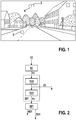
- Figure 1 shows an exemplary image 1, which was captured by an image sensor. Each pixel of the image corresponds to an individual sensor of a sensor matrix of the image sensor. It can be seen that the sky is depicted in an upper area of the exemplary image 1 and an asphalt surface of a road is depicted in a lower area of the exemplary image 1.
- FIG. 1 two exemplary image sections 2, 3 of image 1 are marked.
- the image sensor captures the image 1 with its active surface.
- a corresponding image section 2, 3 of the image 1 captured by the image sensor is also associated with each area of the image sensor.
- the image sections 2, 3 thus also mark two selected areas of the image sensor.
- a first image section 2 corresponds to a first selected area of the image sensor and a second image section 3 corresponds to a second selected area of the image sensor.
- the first image section 2 depicts the sky and thus essentially represents a blue area.
- the second image section 3 depicts the asphalt surface of the road and thus essentially represents a gray area.
- the texturing results from the rough surface of the asphalt pavement and additionally from the noise of the image sensor.
- a slight movement of the image sensor in combination with the rough surface of the asphalt surface can result in a noise-like signal occurring in the area of the second image section 3 even without noise from the image sensor.
- the result is that the first image section 2 is not suitable for forming correspondence, since the textures occurring in the first image section 2 are only based on random statistical processes.
- the second image section 3 is suitable for forming a correspondence, since the textures occurring in the second image section 3 represent actual reference points in the surroundings imaged by the image sensor.
- the image sections 2, 3 can comprise any size and thus any number of image points of the image sensor.
- the selected area of the image sensor comprises only a single pixel of the image sensor and the associated image area 2, 3 thus comprises a single image point.
- the noise of the image sensor can be viewed as a random process, the parameters of which are described statistically.
- the noise of an individual pixel or image point of an image sensor can normally be regarded as independent of the noise of the neighboring pixels.
- all pixels due to the same manufacturing process and the same temperature
- the noise obeys approximately a normal distribution.
- the function h (g) is referred to below as the tone mapping function.
- tone mapping is synonymous with the term dynamic range compression.
- the tone mapping is carried out as a pixel-by-pixel operation (i.e. pixel by pixel, independently of each other). After the tone mapping, the gray value dependency of the noise is eliminated. The variance of the noise is then constant and amounts to ⁇ C 2 .
- the tone mapping function is mostly more complex than described above, especially when it comes to a non-linear image sensor (e.g. HDR sensor, high dynamic range).
- the tone mapping function can be variable over time, e.g. B. change with each recorded image depending on the camera parameters.
- the tone mapping function can be stored in a lookup table or as a calculation rule.
- an image signal processing chain consists at least partially of linear filters: for example, of a smoothing filter, followed by a split into several signal paths, in each signal path further filters can follow, for example smoothing filters, derivative filters, wavelet filters and combinations thereof.
- Figure 2 shows an exemplary excerpt from a signal processing chain for a first image of the image sensor.
- the signal processing chain can be constructed several times, for example twice - for a first image and a comparison image.
- Figure 2 shows a block diagram of a section of signal processing according to an embodiment of the invention.
- An image signal 10, which forms an input signal of a first block 50, is provided by the image sensor.
- the first block therefore forms an input stage which is set up to receive the image signal 10 from the image sensor.
- the first block 50 represents e.g. B. an optional tone mapping, which ensures a gray value g-independent noise with standard deviation ⁇ C.
- An adapted image signal 11, that is to say the image signal 10 after the tone mapping has been applied to the image signal 10, is forwarded from the first block 50 to a second block 100.
- the second block 100 represents e.g. B. is a linear smoothing filter.
- the adjusted image signal is smoothed by the smoothing filter and thus a smoothed image signal 20 is generated.
- the signal path splits up and the smoothed image signal 20 is further processed in several parallel signal paths.
- a first signal path is in Figure 2 shown.
- this includes a third block 101 and a fourth block 301.
- the third block 101 is, for example, a further linear filter, for example a derivative filter, which subtracts two pixel values from a common area around the image 1 from one another .
- a substitute filter 201 can therefore be specified in the signal path, i. in general, as many different substitute filters 201 are to be considered as there are signal paths.
- Such a replacement filter 201 brings about a desired weighted, linear combination of several pixel values (gray values), the filter coefficients representing the weights. At the same time it causes a weighted addition of the independent noise processes.
- the factor ⁇ Y / ⁇ C. ⁇ i w i 2 is therefore an amplification factor for the noise.
- the term gain is to be understood here in a generalized way, because the gain can also have values ⁇ 1. If integer coefficients w i are preferred, however, the gain is usually> 1.
- the prerequisite for the creation of this simple relationship is therefore the uncorrelated nature of the noise processes. This assumption can be made with a very good approximation for image sensors in practice.
- the prerequisite here is that no further relevant filtering takes place between the output of the image sensor or the tone mapping and the substitute filter 201, which would violate the assumption made of uncorrelatedness.
- the information of the first signal path is compressed. I. general non-linear operations performed.
- a roughly quantized (that is, representable with few bits) representation of the input signal of the fourth block 301 is generated as an output signal 401.
- the output signal 401 can represent part of a feature from the image 1 or can be further processed in order to be included in the formation of a feature.
- the output signal 401 and the further formation of features are not considered further here.
- the formation of the features takes place within the framework of the correspondence formation following the signal processing.
- the fourth block 301 there is an evaluation of the input signal s 1 present at this block with regard to noise, which is referred to below as an individual evaluation and by means of which a preliminary evaluation parameter 501 is provided.
- the image signal 10 is evaluated in order to determine the extent to which noise caused by the image sensor is present for a selected area of the image sensor.
- the image signal 10 pre-filtered by the substitute filter 201 is evaluated.
- the preliminary evaluation parameter 501 also describes whether the respective image section 2, 3 is suitable for forming a correspondence, the image section 2, 3 corresponding to the selected area of the image sensor and the evaluation parameter based on the determined The amount of noise is determined.
- the preliminary evaluation parameter 501 is based only on the image signal 10 filtered in advance in the third block 101.
- the preliminary evaluation parameter 501 only provides a statement about the suitability of an image section 2, 3 for forming a correspondence for a specific frequency range of the image signal 10.
- the determination of the preliminary evaluation parameter 501 can consist of a case distinction, a check being made as to whether the amount
- This embodiment with binary-valued preliminary evaluation parameter 501 represents a preferred embodiment.
- Equally advantageous and particularly useful with 0 ⁇ ⁇ i w i is the asymmetrical threshold value comparison, in which it is checked whether the input signal s 1 is inside or outside an interval between z. B. ⁇ 1AL and ⁇ 1AR (with ⁇ 1AL ⁇ 1AR ).
- is compared accordingly of the input signal s 1 with three thresholds ⁇ 1A ⁇ 1B ⁇ 1C , so that four possible states exist and a single evaluation with a word length of two bits is output as a preliminary evaluation parameter 501 at the output of the fourth block 301.
- the respective threshold e.g. ⁇ 1A
- noise properties of the image sensor if necessary, noise properties of the image signal after tone mapping, noise amplification by the substitute filter 201, or more application-specific Parameters, e.g. B. a factor a A.
- ⁇ 1 A. a A. ⁇ ⁇ C. ⁇ ⁇ i w 1 , i 2 .
- p 1 ... 99, whereby the specific value 99 is insignificant here and was chosen only as an example
- ⁇ pA a A. ⁇ ⁇ C. ⁇ ⁇ i w p , i 2 .
- the index A stands for a first threshold ⁇ pA , which can be set with a first application-specific factor a A.
- Corresponding relationships optionally exist for further thresholds, e.g. B. Index B for threshold ⁇ pB and factor a B , and so on.
- Figure 3 shows a larger section of the in Figure 2 signal processing chain shown.
- the in Figure 2 described signal path which is also referred to as the first signal path, the further signal paths are shown.
- a proportional amount of noise is determined for the selected area of the image sensor.
- the proportionate amount of noise can correspond to the amount of noise caused by the image sensor for the selected area of the image sensor.
- the proportionate extent of the noise can, however, also be limited to certain properties of the image signal 10, in particular a frequency range.
- a number of p signal paths are shown.
- a p-th signal path with p ⁇ ⁇ 1, ..., 99 ⁇ contains a linear filter 102, 103, ..., 199 (here thus denoted by the reference symbol 100 + p), which corresponds to the third block 101.
- the linear filters 102, 103,..., 199 have different filter properties in order to share those associated with the signal paths Determine the amount of noise.
- a combination of the respective linear filter 102, 103, ..., 199 of a signal path with the upstream linear filter of the second block 100 are referred to as the substitute filters 201, 202, ..., 299 associated with the respective signal path (reference characters 200 + p) .
- the linear filters 101, 102,..., 199 are advantageously all different from one another.
- the replacement filters 201, 202,..., 299 are also different accordingly.
- the multiple associated components of the scope of the noise are each associated with different frequency ranges of the image signal 10.
- a p-th signal path with p ⁇ ⁇ 1 ... 99 ⁇ also contains a block 301, 302, 303, ... 399, which corresponds to the fourth block 301 of the first signal path.
- the replacement filters 201, 202, ..., 299 together with the blocks 301, 302, 303, ... 399 and an optional combination block 600 result in an evaluation stage.
- This is set up to evaluate the image signal 10 in order to determine the extent to which there is noise caused by the image sensor for a selected area of the image sensor, and to determine a resulting evaluation parameter 601 for the image section 2, 3 of the image captured by the image sensor , which describes whether the image section 2, 3 is suitable for forming a correspondence, the image section 2, 3 corresponding to the selected area of the image sensor and the resulting evaluation parameter 601 being determined based on the specific amount of noise.
- the signals s p with p ⁇ ⁇ 1, ..., 99 ⁇ are present at the inputs of blocks 301, 302, 303, ..., 399.
- an individual evaluation of an input signal takes place in these blocks 301, 302, 303,..., 399 as well as in the fourth block 301, with one or more threshold value comparisons being carried out for the magnitude
- preliminary evaluation parameters 501, 502, 503,... 599 are provided as preliminary evaluation parameters 501, 502, 503,... 599 and passed on to an optional combination block 600.
- the task of the combination block 600 is to compress information. This is characterized in that an output signal of the combination block 600 can be described with fewer bits than the entirety of the input signals, that is to say the preliminary evaluation parameters 501, 502, 503,..., 599.
- the output signal then has i. generally a lower entropy. There is a loss of information, which is consciously accepted, e.g. B. to achieve the advantage of a small word length and to save transmission bandwidth.
- the output signal of the combination block 600 is the resulting evaluation parameter 601.
- the combination block 600 thus combines the preliminary evaluation parameters 501, 502, 503,..., 599 to form the resulting evaluation parameter 601.
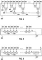
- the Figures 4, 5 and 6 show alternative exemplary embodiments of how the combination block 600 can be constructed.
- Figure 4 shows a first logic circuit for combining a plurality of preliminary evaluation parameters 501, 502, 503,..., 599 to form a resulting evaluation parameter 601, which in an advantageous embodiment of the invention is the combination block 600.
- the preliminary evaluation parameters 501, 502, 503, ..., 599 are assumed to be binary-valued input signals.
- three of the preliminary evaluation parameters 501, 502, 503,..., 599 form a group and are logically linked by means of two OR gates 602, 603. This means that a logical "1" is output as an intermediate result for the respective group at an output side of the OR gates 602, 603 if at least one of the preliminary evaluation parameters 501, 502, 503, ..., 599 of this group has a logical " 1 "has taken as the value.
- the binary intermediate results of all groups are coupled via a multiplicity of adders 604 and are thus added.
- the output signal of the combination block 600 has a value range of 0 - 33. This corresponds to an entropy of less than 6 bits, while a total of 99 bits are added for the preliminary evaluation parameters 501, 502, 503, ..., 599 are transferred. A first compression of information is thus achieved in this way.
- the added intermediate results are referred to as the sum signal s x and provided at an output of the combination block 600 as the resulting evaluation parameter 601.
- the resulting evaluation parameter 601 thus has a range of values which, through the individual values in several stages, describes a degree of suitability of the respectively viewed image section 2, 3 describes for the formation of correspondence.
- Figure 5 shows a second logic circuit for combining several preliminary evaluation parameters 501, 502, 503,..., 599 to form a resulting evaluation parameter 601, which is the combination block 600 in an advantageous embodiment of the invention.
- Fig. 5 shows one opposite the in Figure 4
- the logic circuit shown simplifies the possibility of information compression, namely by simply adding the preliminary evaluation parameters 501, 502, 503, ..., 599, which do not have to be binary, but can also cover larger value ranges.
- all inputs of the combination block 600, at which the preliminary evaluation parameters 501, 502, 503, ..., 599 are provided to the combination block 600 are coupled via a plurality of adders 604, so that all of the preliminary evaluation parameters 501, 502, 503, ..., 599 can be added up.
- the added preliminary evaluation parameters 501, 502, 503,..., 599 are referred to as the sum signal s x and provided at an output of the combination block 600 as the resulting evaluation parameter 601.
- Figure 6 shows a third logic circuit for combining a plurality of preliminary evaluation parameters 501, 502, 503,..., 599 to form a resulting evaluation parameter 601, which in an advantageous embodiment of the invention is the combination block 600.
- the in Figure 6 The combination block 600 shown is constructed similarly to that of Fig. 5 known combination block 600, but the sum signal s x is compared with a threshold value T 1 before being made available at the output of the combination block and the result of this comparison is output as binary information.
- the resulting evaluation parameter 601 is thus a binary value.
- a preliminary evaluation parameter 501, 502, 503, ..., 599 is determined by each of the p signal paths, each of the preliminary evaluation parameters 501, 502, 503, ..., 599 being based on a proportional amount of the noise, wherein the proportional extent of the noise depends on the replacement filter 201, 202, 203, ..., 299 used in the respective signal path.
- the preliminary Evaluation parameters 501, 502, 503, ..., 599 combined to form the resulting evaluation parameter 601.
- the resulting evaluation parameter 601 for the image section 2, 3 under consideration is determined based on a noise that results from a combination of individual The proportions of the noise, here the proportions of the noise, results.
- combination block 600 there are a number of other possibilities for designing the combination block 600 in order to suitably combine the preliminary evaluation parameters 501, 502, 503, ..., 599 with one another, for example with logical operations (AND, OR, XOR, NOT etc.), arithmetic operations ( Addition, multiplication, etc.), threshold comparisons, quantization, lookup tables, and so on.
- logical operations AND, OR, XOR, NOT etc.
- arithmetic operations Addition, multiplication, etc.
- threshold comparisons quantization, lookup tables, and so on.
- the combination of these operations can either be "designed” or “trained” on the basis of training data.
- the decisive factor here is that the individual evaluations and thus the preliminary evaluation parameters 501, 502, 503, ..., 599 are linked to form a condensed evaluation, so that the condensed evaluation already provides relatively reliable information on whether and, if so, how far the signal just processed, which is provided as output signal 401, 402, 403, ..., 499, stands out from the noise.
- This condensed evaluation can be binary or have a larger range of values.
- This condensed evaluation can also be vector-valued.
- not only a binary or "multi-valued" item of information is output, but rather several items that can be viewed together as a vector.
- the in Figure 4 and Figure 5 Proposed examples for combining individual evaluations are not considered as alternatives, but can both be implemented together in the combination block 600, so that the result of the combination block 600 and thus the resulting evaluation parameter 601 is a two-dimensional vector.
- a stabilization function is applied to the output signal of the combination block 600 and thus to the resulting evaluation parameter 601. This is in Figure 3 represented by a stabilization block 700.
- the optional stabilization block 700 uses spatial and / or temporal statistical dependencies in order to stabilize the result. For example, by using the intermediate results of the in Figure 5 The combination block 600 shown, which have a value range 0-99, are added up weighted in a spatial-temporal pixel neighborhood and compared with a threshold.
- the image signal 10 is evaluated in order to determine a level of noise for a plurality of selected image sections 2, 3 of the image sensor in order to determine a plurality of resulting evaluation parameters 601.
- the in Figure 3 Signal processing shown carried out. If the signal processing is carried out for each pixel of the image sensor, the result is that a resulting evaluation parameter 601 is determined for each pixel.
- a stabilization function is applied to the resulting evaluation parameter 601, which is associated, for example, with the first image section 2, with an adaptation of a value of the resulting evaluation parameter 601 of the first image section 2 to a resulting evaluation parameter of the first Image section 2 of adjacent image section 4 takes place.
- all the resulting evaluation parameters 601 determined are temporarily stored at least for a short time, so that the respective resulting evaluation parameters of the neighboring pixels can be accessed for each pixel and thus for each image section 2, 3.
- the reference pixel 6 corresponds to the pixel of the image sensor through which the first image section 2 is captured.
- the adjacent pixel 7 located to the left of the reference pixel 6 corresponds to a pixel of the image sensor by which an image segment 4 adjacent to the first image segment 2 is captured.
- the resulting evaluation parameter 601 stabilized in this way is output as an output value s 2 and can optionally be compared with a threshold T 2 , which z. B. has a value of "700". As an alternative to this threshold value decision, quantization can also take place. B. the 0 - 1386 value range to a smaller value range of z. B. 0 - 7 maps.
- the smoothing filter provided by the stabilization block 700 is not necessarily constructed symmetrically, nor does it have to be densely populated. Any shapes and dimensions can prove to be advantageous and can be determined experimentally, for example.
- the spatial weighted summation requires i. general. an intermediate buffering of the resulting evaluation parameters 601 and i. generally also to a delay, because the final result for the respective (reference) pixel can only be calculated when all further intermediate results are available.
- the weighted summation can additionally or alternatively also be carried out in the time direction.
- z For example, buffered intermediate results from an earlier calculation (e.g. for the previous image) are included. This inclusion takes place, if necessary, using motion compensation, for example to compensate for a rotation of a camera which includes the image sensor.
- the result of the stabilization block 700 is a decision (in the case of a binary result) or an assessment (in the case of a result that is more than binary) about the noise at the respective pixel.
- the binary values can have the following interpretation.
- the stabilized resulting movement parameter 701 is provided at the output of the stabilization block 700.
- the stabilization block 700 is optional.
- the meanings of the values of the stabilized resulting movement parameter 601 described below can be applied in the same way directly to the (non-stabilized) resulting movement parameter 601.
- the selected sequence of the combination block 600 and the stabilization block 700 is to be understood here merely as an example. It can also be reversed in order to first include the spatial / temporal neighborhood and then to achieve a compression of information.
- the functions of these blocks 600, 700 can also be interwoven with one another and represented in a common block.
- the method according to the invention makes it possible to specify additional information on a feature which, depending on the "distance to noise", expresses a greater or lesser degree of confidence in this feature, whereby this confidence or quality measure can be described very compactly (e.g. with 1 Bit or with a few bits) and can be passed on to subsequent algorithms or efficiently stored for further use.
- the information according to the invention is determined and appended per pixel or per feature.
- it is also possible to determine and provide these less frequently for example in each case for a group of pixels or features or else as a binary image, which can then be encoded and decoded using known methods for data compression.
- a representation with less than 1 bit per pixel or feature is also possible.
Claims (8)
- Procédé permettant d'évaluer des sections d'image pour l'établissement d'une correspondance, dans lequel des particularités qui se correspondent sur deux images individuelles sont déterminées, comprenant les étapes consistant à :- recevoir un signal d'image (10) d'un capteur d'image,- évaluer le signal d'image (10) afin de déterminer l'ampleur du bruit provoqué par le capteur d'image pour une zone sélectionnée du capteur d'image, et- déterminer un paramètre d'évaluation résultant (601) pour une section d'image (2, 3) d'une image détectée par le capteur d'image qui décrit si la section d'image (2, 3) convient à l'établissement d'une correspondance, dans lequel la section d'image (2, 3) correspond à la zone sélectionnée du capteur d'image, et le paramètre d'évaluation résultant (601) est déterminé sur la base de l'ampleur déterminée du bruit, caractérisé en ce que pour la zone sélectionnée du capteur d'image respectivement une ampleur proportionnelle du bruit est déterminée sur différents chemins de signal en ce que le signal d'image (10) est filtré différemment respectivement sur les différents chemins de signal, et le paramètre d'évaluation résultant (601) est déterminé pour la section d'image (2, 3) sur la base de l'ampleur proportionnelle respective du bruit provenant de tous les chemins de signal.
- Procédé selon la revendication 1, caractérisé en ce que différentes plages de fréquence du signal d'image sont respectivement associées à chaque ampleur proportionnelle du bruit.
- Procédé selon l'une quelconque des revendications 1 et 2, caractérisé en ce qu'à partir de chaque ampleur proportionnelle du bruit, un paramètre d'évaluation provisoire (501, 502, 503, ..., 599) est déterminé, et les paramètres d'évaluation provisoires (501, 502, 503, ..., 599) sont regroupés pour former le paramètre d'évaluation résultant (601).
- Procédé selon l'une quelconque des revendications précédentes, caractérisé en ce qu'une compression dynamique est appliquée au signal d'image (10) avant que l'évaluation du signal d'image (10) ne soit effectuée.
- Procédé selon l'une quelconque des revendications précédentes, caractérisé en ce que le paramètre d'évaluation résultant (601) est une valeur binaire, indique un degré d'une aptitude à l'établissement d'une correspondance ou est une valeur vectorielle.
- Procédé selon l'une quelconque des revendications précédentes, caractérisé en ce que l'évaluation du signal d'image (10) pour déterminer une ampleur du bruit est effectuée pour plusieurs zones sélectionnées du capteur d'image afin de déterminer plusieurs paramètres d'évaluation résultants (601).
- Procédé selon la revendication 6, caractérisé en ce que sur l'un des paramètres d'évaluation résultants (601), qui appartient à une première section d'image (2), une fonction de stabilisation est appliquée, un filtrage local et/ou temporel étant effectué à l'aide de paramètres d'évaluation résultants (601) voisins.
- Dispositif permettant d'évaluer des sections d'image pour l'établissement d'une correspondance, des particularités qui se correspondent étant déterminées sur deux images individuelles, comprenant :un étage d'entrée (50) qui est aménagé pour recevoir un signal d'image (10) d'un capteur d'image, etun étage d'évaluation qui est aménagé pour :• évaluer le signal d'image (10) afin de déterminer l'ampleur du bruit provoqué par le capteur d'image pour une zone sélectionnée du capteur d'image,• déterminer un paramètre d'évaluation résultant (601) pour une section d'image (2, 3) d'une image détectée par le capteur d'image qui décrit si la section d'image (2, 3) convient à l'établissement d'une correspondance, dans lequel la section d'image (2, 3) correspond à la zone sélectionnée du capteur d'image, et le paramètre d'évaluation résultant (601) est déterminé sur la base de l'ampleur déterminée du bruit,caractérisé en ce que pour la zone sélectionnée du capteur d'image respectivement une ampleur proportionnelle du bruit est déterminée sur différents chemins de signal en ce que le signal d'image (10) est filtré différemment respectivement sur les différents chemins de signal, et le paramètre d'évaluation résultant (601) est déterminé pour la section d'image (2, 3) sur la base de l'ampleur proportionnelle respective du bruit provenant de tous les chemins de signal.
Applications Claiming Priority (2)
| Application Number | Priority Date | Filing Date | Title |
|---|---|---|---|
| DE102017212339.7A DE102017212339A1 (de) | 2017-07-19 | 2017-07-19 | Verfahren und Vorrichtung zur Bewertung von Bildausschnitten für eine Korrespondenzbildung |
| PCT/EP2018/065317 WO2019015877A1 (fr) | 2017-07-19 | 2018-06-11 | Procédé et dispositif pour l'évaluation de sections d'images pour un calcul de correspondance |
Publications (2)
| Publication Number | Publication Date |
|---|---|
| EP3655920A1 EP3655920A1 (fr) | 2020-05-27 |
| EP3655920B1 true EP3655920B1 (fr) | 2021-03-31 |
Family
ID=62599592
Family Applications (1)
| Application Number | Title | Priority Date | Filing Date |
|---|---|---|---|
| EP18731048.7A Active EP3655920B1 (fr) | 2017-07-19 | 2018-06-11 | Procédé et dispositif pour l'évaluation de sections d'images pour un calcul de correspondance |
Country Status (6)
| Country | Link |
|---|---|
| US (1) | US11100624B2 (fr) |
| EP (1) | EP3655920B1 (fr) |
| JP (1) | JP6889327B2 (fr) |
| CN (1) | CN110998652B (fr) |
| DE (1) | DE102017212339A1 (fr) |
| WO (1) | WO2019015877A1 (fr) |
Families Citing this family (2)
| Publication number | Priority date | Publication date | Assignee | Title |
|---|---|---|---|---|
| DE102017212339A1 (de) * | 2017-07-19 | 2019-01-24 | Robert Bosch Gmbh | Verfahren und Vorrichtung zur Bewertung von Bildausschnitten für eine Korrespondenzbildung |
| DE102020202973A1 (de) | 2020-03-09 | 2021-09-09 | Robert Bosch Gesellschaft mit beschränkter Haftung | Verfahren und Vorrichtung zum Verarbeiten von Bildern |
Family Cites Families (28)
| Publication number | Priority date | Publication date | Assignee | Title |
|---|---|---|---|---|
| JP3465988B2 (ja) * | 1994-04-27 | 2003-11-10 | 松下電器産業株式会社 | 動き及び奥行き推定方法及びその装置 |
| AU2002347754A1 (en) * | 2002-11-06 | 2004-06-07 | Agency For Science, Technology And Research | A method for generating a quality oriented significance map for assessing the quality of an image or video |
| US7512286B2 (en) * | 2003-10-27 | 2009-03-31 | Hewlett-Packard Development Company, L.P. | Assessing image quality |
| US7693304B2 (en) * | 2005-05-12 | 2010-04-06 | Hewlett-Packard Development Company, L.P. | Method and system for image quality calculation |
| GB2443663A (en) * | 2006-07-31 | 2008-05-14 | Hewlett Packard Development Co | Electronic image capture with reduced noise |
| JP4821548B2 (ja) * | 2006-10-02 | 2011-11-24 | コニカミノルタホールディングス株式会社 | 画像処理装置、画像処理装置の制御方法、および画像処理装置の制御プログラム |
| DE102007003060A1 (de) | 2007-01-15 | 2008-07-17 | Technische Universität Ilmenau | Verfahren zur Bestimmung der Güte eines Messpunktes bei der Kantendetektion in der optischen Längenmesstechnik |
| JP2009104366A (ja) * | 2007-10-23 | 2009-05-14 | Suzuki Motor Corp | ステレオ画像処理方法 |
| RU2405200C2 (ru) * | 2008-07-17 | 2010-11-27 | Корпорация "Самсунг Электроникс Ко., Лтд" | Способ и устройство быстрого фильтрования шума цифровых изображений |
| US20100277774A1 (en) * | 2009-05-04 | 2010-11-04 | Certifi Media Inc. | Image quality indicator responsive to image processing |
| EP2275990B1 (fr) | 2009-07-06 | 2012-09-26 | Sick Ag | Capteur 3D |
| JP5701874B2 (ja) * | 2009-07-21 | 2015-04-15 | クゥアルコム・インコーポレイテッドQualcomm Incorporated | ビデオ画像の検出およびエンハンスメントのための方法およびシステム |
| RU2441281C1 (ru) * | 2011-01-14 | 2012-01-27 | Закрытое Акционерное Общество "Импульс" | Способ оценки шума цифровых рентгенограмм |
| US8792710B2 (en) * | 2012-07-24 | 2014-07-29 | Intel Corporation | Stereoscopic depth reconstruction with probabilistic pixel correspondence search |
| JP5997645B2 (ja) * | 2013-03-26 | 2016-09-28 | キヤノン株式会社 | 画像処理装置及び方法、及び撮像装置 |
| EP2808841A1 (fr) * | 2013-05-31 | 2014-12-03 | Thomson Licensing | Procédé et appareil pour générer un profil de bruit dans une séquence d'images |
| JP6369019B2 (ja) * | 2013-12-12 | 2018-08-08 | セイコーエプソン株式会社 | 画像評価装置および画像評価プログラム |
| JP6253450B2 (ja) * | 2014-02-28 | 2017-12-27 | オリンパス株式会社 | 画像処理装置、画像処理方法及びプログラム |
| JP6415066B2 (ja) * | 2014-03-20 | 2018-10-31 | キヤノン株式会社 | 情報処理装置、情報処理方法、位置姿勢推定装置、ロボットシステム |
| US9330340B1 (en) * | 2014-05-06 | 2016-05-03 | Google Inc. | Noise estimation for images using polynomial relationship for pixel values of image features |
| JP6397284B2 (ja) * | 2014-09-16 | 2018-09-26 | キヤノン株式会社 | 画像処理装置、画像処理方法及びプログラム |
| CN107408196B (zh) * | 2014-12-19 | 2021-03-19 | 顶级公司 | 从图像中提取特征的方法 |
| PL411631A1 (pl) * | 2015-03-18 | 2016-09-26 | Politechnika Poznańska | System do generowania mapy głębi i sposób generowania mapy głębi |
| JP6548556B2 (ja) * | 2015-11-17 | 2019-07-24 | 富士フイルム株式会社 | グリッド品質判定装置、方法およびプログラム |
| US9922411B2 (en) * | 2015-11-30 | 2018-03-20 | Disney Enterprises, Inc. | Saliency-weighted video quality assessment |
| DE102017212339A1 (de) * | 2017-07-19 | 2019-01-24 | Robert Bosch Gmbh | Verfahren und Vorrichtung zur Bewertung von Bildausschnitten für eine Korrespondenzbildung |
| KR102466998B1 (ko) * | 2018-02-09 | 2022-11-14 | 삼성전자주식회사 | 영상 융합 방법 및 장치 |
| JP7412983B2 (ja) * | 2019-02-04 | 2024-01-15 | キヤノン株式会社 | 情報処理装置、情報処理方法、及びプログラム |
-
2017
- 2017-07-19 DE DE102017212339.7A patent/DE102017212339A1/de active Pending
-
2018
- 2018-06-11 EP EP18731048.7A patent/EP3655920B1/fr active Active
- 2018-06-11 JP JP2020502319A patent/JP6889327B2/ja active Active
- 2018-06-11 WO PCT/EP2018/065317 patent/WO2019015877A1/fr unknown
- 2018-06-11 US US16/631,694 patent/US11100624B2/en active Active
- 2018-06-11 CN CN201880048314.5A patent/CN110998652B/zh active Active
Also Published As
| Publication number | Publication date |
|---|---|
| JP6889327B2 (ja) | 2021-06-18 |
| CN110998652B (zh) | 2024-02-09 |
| EP3655920A1 (fr) | 2020-05-27 |
| US11100624B2 (en) | 2021-08-24 |
| JP2020528182A (ja) | 2020-09-17 |
| US20200151864A1 (en) | 2020-05-14 |
| CN110998652A (zh) | 2020-04-10 |
| WO2019015877A1 (fr) | 2019-01-24 |
| DE102017212339A1 (de) | 2019-01-24 |
Similar Documents
| Publication | Publication Date | Title |
|---|---|---|
| DE602005004694T2 (de) | Verfahren und Vorrichtung für lokal adaptive Bildverarbeitungsfilter | |
| DE60017600T2 (de) | Digitales bilderzeugungsverfahren | |
| DE102005025629A1 (de) | Bildverarbeitungsverfahren zur Reduzierung von Blocking-Artefakten | |
| DE112016001040T5 (de) | Verfahren und System zur Echtzeit-Rauschbeseitung und -Bildverbesserung von Bildern mit hohem Dynamikumfang | |
| DE10239801A1 (de) | Verfahren zum Extrahieren von Texturmerkmalen aus einem mehrkanaligen Bild | |
| DE102016216795A1 (de) | Verfahren zur Ermittlung von Ergebnisbilddaten | |
| EP3655920B1 (fr) | Procédé et dispositif pour l'évaluation de sections d'images pour un calcul de correspondance | |
| DE4105516A1 (de) | Verfahren und vorrichtung zur filterung von signalen | |
| DE102020134755A1 (de) | Verarbeiten von videoframes über neuronales faltungsnetzwerk durch verwenden von statistiken vorhergehender frames | |
| DE102007037857A1 (de) | Verfahren zur Reduktion von Bildartefakten | |
| EP0897247A2 (fr) | Procédé de calcul de vecteurs de mouvement | |
| EP1156681A2 (fr) | Méthode et dispositif de mesure du bruit d'une image | |
| DE102008046505B4 (de) | Verfahren zur Bildverarbeitung von Stereobildern | |
| DE19851544C1 (de) | Erzeugen eines abgerollten Fingerabdruckbildes aus einer Serie von Einzelbildern | |
| DE60306800T2 (de) | Verfahren und system zur messung von videobildverschlechterung, hervorgerufen durch kodierung zur bitratenreduktion | |
| EP3142068B1 (fr) | Procede de detection tridimensionnelle d'objets | |
| DE102021101468A1 (de) | Verfahren zur Erzeugung valider Entfernungsdaten für eine Lichtlaufzeitkamera | |
| AT508873A1 (de) | Verfahren zur aufnahme eines bildes | |
| EP3214602A1 (fr) | Procédé de détection tridimensionnelle d'objets | |
| DE102009009572B3 (de) | Verfahren zur entropiebasierten Bestimmung von Objektrandkurven | |
| DE10326031B4 (de) | Verfahren zur adaptiven Kantenerkennung | |
| EP1185084A2 (fr) | Procédé de codage d'image et codeur d'image | |
| WO2019072454A1 (fr) | Optimisation de luminosité et de contraste d'images en temps réel | |
| DE19810162C2 (de) | Verfahren zur Bildanalyse nach stochastischen Eigenschaften | |
| EP2501133A2 (fr) | Procédé et dispositif destinés à la réduction de largeurs de bande pour données d'images |
Legal Events
| Date | Code | Title | Description |
|---|---|---|---|
| STAA | Information on the status of an ep patent application or granted ep patent |
Free format text: STATUS: UNKNOWN |
|
| STAA | Information on the status of an ep patent application or granted ep patent |
Free format text: STATUS: THE INTERNATIONAL PUBLICATION HAS BEEN MADE |
|
| PUAI | Public reference made under article 153(3) epc to a published international application that has entered the european phase |
Free format text: ORIGINAL CODE: 0009012 |
|
| STAA | Information on the status of an ep patent application or granted ep patent |
Free format text: STATUS: REQUEST FOR EXAMINATION WAS MADE |
|
| 17P | Request for examination filed |
Effective date: 20200219 |
|
| AK | Designated contracting states |
Kind code of ref document: A1 Designated state(s): AL AT BE BG CH CY CZ DE DK EE ES FI FR GB GR HR HU IE IS IT LI LT LU LV MC MK MT NL NO PL PT RO RS SE SI SK SM TR |
|
| AX | Request for extension of the european patent |
Extension state: BA ME |
|
| DAV | Request for validation of the european patent (deleted) | ||
| DAX | Request for extension of the european patent (deleted) | ||
| GRAP | Despatch of communication of intention to grant a patent |
Free format text: ORIGINAL CODE: EPIDOSNIGR1 |
|
| STAA | Information on the status of an ep patent application or granted ep patent |
Free format text: STATUS: GRANT OF PATENT IS INTENDED |
|
| INTG | Intention to grant announced |
Effective date: 20210118 |
|
| GRAS | Grant fee paid |
Free format text: ORIGINAL CODE: EPIDOSNIGR3 |
|
| GRAA | (expected) grant |
Free format text: ORIGINAL CODE: 0009210 |
|
| STAA | Information on the status of an ep patent application or granted ep patent |
Free format text: STATUS: THE PATENT HAS BEEN GRANTED |
|
| AK | Designated contracting states |
Kind code of ref document: B1 Designated state(s): AL AT BE BG CH CY CZ DE DK EE ES FI FR GB GR HR HU IE IS IT LI LT LU LV MC MK MT NL NO PL PT RO RS SE SI SK SM TR |
|
| REG | Reference to a national code |
Ref country code: GB Ref legal event code: FG4D Free format text: NOT ENGLISH Ref country code: CH Ref legal event code: EP |
|
| REG | Reference to a national code |
Ref country code: AT Ref legal event code: REF Ref document number: 1377792 Country of ref document: AT Kind code of ref document: T Effective date: 20210415 |
|
| REG | Reference to a national code |
Ref country code: DE Ref legal event code: R096 Ref document number: 502018004565 Country of ref document: DE |
|
| REG | Reference to a national code |
Ref country code: IE Ref legal event code: FG4D Free format text: LANGUAGE OF EP DOCUMENT: GERMAN |
|
| REG | Reference to a national code |
Ref country code: LT Ref legal event code: MG9D |
|
| PG25 | Lapsed in a contracting state [announced via postgrant information from national office to epo] |
Ref country code: NO Free format text: LAPSE BECAUSE OF FAILURE TO SUBMIT A TRANSLATION OF THE DESCRIPTION OR TO PAY THE FEE WITHIN THE PRESCRIBED TIME-LIMIT Effective date: 20210630 Ref country code: HR Free format text: LAPSE BECAUSE OF FAILURE TO SUBMIT A TRANSLATION OF THE DESCRIPTION OR TO PAY THE FEE WITHIN THE PRESCRIBED TIME-LIMIT Effective date: 20210331 Ref country code: FI Free format text: LAPSE BECAUSE OF FAILURE TO SUBMIT A TRANSLATION OF THE DESCRIPTION OR TO PAY THE FEE WITHIN THE PRESCRIBED TIME-LIMIT Effective date: 20210331 Ref country code: BG Free format text: LAPSE BECAUSE OF FAILURE TO SUBMIT A TRANSLATION OF THE DESCRIPTION OR TO PAY THE FEE WITHIN THE PRESCRIBED TIME-LIMIT Effective date: 20210630 |
|
| PG25 | Lapsed in a contracting state [announced via postgrant information from national office to epo] |
Ref country code: SE Free format text: LAPSE BECAUSE OF FAILURE TO SUBMIT A TRANSLATION OF THE DESCRIPTION OR TO PAY THE FEE WITHIN THE PRESCRIBED TIME-LIMIT Effective date: 20210331 Ref country code: RS Free format text: LAPSE BECAUSE OF FAILURE TO SUBMIT A TRANSLATION OF THE DESCRIPTION OR TO PAY THE FEE WITHIN THE PRESCRIBED TIME-LIMIT Effective date: 20210331 Ref country code: LV Free format text: LAPSE BECAUSE OF FAILURE TO SUBMIT A TRANSLATION OF THE DESCRIPTION OR TO PAY THE FEE WITHIN THE PRESCRIBED TIME-LIMIT Effective date: 20210331 |
|
| REG | Reference to a national code |
Ref country code: NL Ref legal event code: MP Effective date: 20210331 |
|
| PG25 | Lapsed in a contracting state [announced via postgrant information from national office to epo] |
Ref country code: EE Free format text: LAPSE BECAUSE OF FAILURE TO SUBMIT A TRANSLATION OF THE DESCRIPTION OR TO PAY THE FEE WITHIN THE PRESCRIBED TIME-LIMIT Effective date: 20210331 Ref country code: CZ Free format text: LAPSE BECAUSE OF FAILURE TO SUBMIT A TRANSLATION OF THE DESCRIPTION OR TO PAY THE FEE WITHIN THE PRESCRIBED TIME-LIMIT Effective date: 20210331 Ref country code: LT Free format text: LAPSE BECAUSE OF FAILURE TO SUBMIT A TRANSLATION OF THE DESCRIPTION OR TO PAY THE FEE WITHIN THE PRESCRIBED TIME-LIMIT Effective date: 20210331 Ref country code: SM Free format text: LAPSE BECAUSE OF FAILURE TO SUBMIT A TRANSLATION OF THE DESCRIPTION OR TO PAY THE FEE WITHIN THE PRESCRIBED TIME-LIMIT Effective date: 20210331 Ref country code: NL Free format text: LAPSE BECAUSE OF FAILURE TO SUBMIT A TRANSLATION OF THE DESCRIPTION OR TO PAY THE FEE WITHIN THE PRESCRIBED TIME-LIMIT Effective date: 20210331 |
|
| PG25 | Lapsed in a contracting state [announced via postgrant information from national office to epo] |
Ref country code: PL Free format text: LAPSE BECAUSE OF FAILURE TO SUBMIT A TRANSLATION OF THE DESCRIPTION OR TO PAY THE FEE WITHIN THE PRESCRIBED TIME-LIMIT Effective date: 20210331 Ref country code: PT Free format text: LAPSE BECAUSE OF FAILURE TO SUBMIT A TRANSLATION OF THE DESCRIPTION OR TO PAY THE FEE WITHIN THE PRESCRIBED TIME-LIMIT Effective date: 20210802 Ref country code: RO Free format text: LAPSE BECAUSE OF FAILURE TO SUBMIT A TRANSLATION OF THE DESCRIPTION OR TO PAY THE FEE WITHIN THE PRESCRIBED TIME-LIMIT Effective date: 20210331 Ref country code: SK Free format text: LAPSE BECAUSE OF FAILURE TO SUBMIT A TRANSLATION OF THE DESCRIPTION OR TO PAY THE FEE WITHIN THE PRESCRIBED TIME-LIMIT Effective date: 20210331 Ref country code: IS Free format text: LAPSE BECAUSE OF FAILURE TO SUBMIT A TRANSLATION OF THE DESCRIPTION OR TO PAY THE FEE WITHIN THE PRESCRIBED TIME-LIMIT Effective date: 20210731 |
|
| REG | Reference to a national code |
Ref country code: DE Ref legal event code: R097 Ref document number: 502018004565 Country of ref document: DE |
|
| PG25 | Lapsed in a contracting state [announced via postgrant information from national office to epo] |
Ref country code: ES Free format text: LAPSE BECAUSE OF FAILURE TO SUBMIT A TRANSLATION OF THE DESCRIPTION OR TO PAY THE FEE WITHIN THE PRESCRIBED TIME-LIMIT Effective date: 20210331 Ref country code: DK Free format text: LAPSE BECAUSE OF FAILURE TO SUBMIT A TRANSLATION OF THE DESCRIPTION OR TO PAY THE FEE WITHIN THE PRESCRIBED TIME-LIMIT Effective date: 20210331 Ref country code: AL Free format text: LAPSE BECAUSE OF FAILURE TO SUBMIT A TRANSLATION OF THE DESCRIPTION OR TO PAY THE FEE WITHIN THE PRESCRIBED TIME-LIMIT Effective date: 20210331 Ref country code: MC Free format text: LAPSE BECAUSE OF FAILURE TO SUBMIT A TRANSLATION OF THE DESCRIPTION OR TO PAY THE FEE WITHIN THE PRESCRIBED TIME-LIMIT Effective date: 20210331 |
|
| REG | Reference to a national code |
Ref country code: CH Ref legal event code: PL |
|
| PLBE | No opposition filed within time limit |
Free format text: ORIGINAL CODE: 0009261 |
|
| STAA | Information on the status of an ep patent application or granted ep patent |
Free format text: STATUS: NO OPPOSITION FILED WITHIN TIME LIMIT |
|
| 26N | No opposition filed |
Effective date: 20220104 |
|
| REG | Reference to a national code |
Ref country code: BE Ref legal event code: MM Effective date: 20210630 |
|
| PG25 | Lapsed in a contracting state [announced via postgrant information from national office to epo] |
Ref country code: LU Free format text: LAPSE BECAUSE OF NON-PAYMENT OF DUE FEES Effective date: 20210611 |
|
| PG25 | Lapsed in a contracting state [announced via postgrant information from national office to epo] |
Ref country code: LI Free format text: LAPSE BECAUSE OF NON-PAYMENT OF DUE FEES Effective date: 20210630 Ref country code: CH Free format text: LAPSE BECAUSE OF NON-PAYMENT OF DUE FEES Effective date: 20210630 Ref country code: IE Free format text: LAPSE BECAUSE OF NON-PAYMENT OF DUE FEES Effective date: 20210611 |
|
| PG25 | Lapsed in a contracting state [announced via postgrant information from national office to epo] |
Ref country code: IS Free format text: LAPSE BECAUSE OF FAILURE TO SUBMIT A TRANSLATION OF THE DESCRIPTION OR TO PAY THE FEE WITHIN THE PRESCRIBED TIME-LIMIT Effective date: 20210731 |
|
| PG25 | Lapsed in a contracting state [announced via postgrant information from national office to epo] |
Ref country code: BE Free format text: LAPSE BECAUSE OF NON-PAYMENT OF DUE FEES Effective date: 20210630 |
|
| GBPC | Gb: european patent ceased through non-payment of renewal fee |
Effective date: 20220611 |
|
| PG25 | Lapsed in a contracting state [announced via postgrant information from national office to epo] |
Ref country code: GB Free format text: LAPSE BECAUSE OF NON-PAYMENT OF DUE FEES Effective date: 20220611 |
|
| P01 | Opt-out of the competence of the unified patent court (upc) registered |
Effective date: 20230509 |
|
| PG25 | Lapsed in a contracting state [announced via postgrant information from national office to epo] |
Ref country code: CY Free format text: LAPSE BECAUSE OF FAILURE TO SUBMIT A TRANSLATION OF THE DESCRIPTION OR TO PAY THE FEE WITHIN THE PRESCRIBED TIME-LIMIT Effective date: 20210331 |
|
| PG25 | Lapsed in a contracting state [announced via postgrant information from national office to epo] |
Ref country code: HU Free format text: LAPSE BECAUSE OF FAILURE TO SUBMIT A TRANSLATION OF THE DESCRIPTION OR TO PAY THE FEE WITHIN THE PRESCRIBED TIME-LIMIT; INVALID AB INITIO Effective date: 20180611 Ref country code: GR Free format text: LAPSE BECAUSE OF FAILURE TO SUBMIT A TRANSLATION OF THE DESCRIPTION OR TO PAY THE FEE WITHIN THE PRESCRIBED TIME-LIMIT Effective date: 20210331 |
|
| PGFP | Annual fee paid to national office [announced via postgrant information from national office to epo] |
Ref country code: FR Payment date: 20230621 Year of fee payment: 6 |
|
| PGFP | Annual fee paid to national office [announced via postgrant information from national office to epo] |
Ref country code: IT Payment date: 20230630 Year of fee payment: 6 |
|
| PGFP | Annual fee paid to national office [announced via postgrant information from national office to epo] |
Ref country code: DE Payment date: 20230817 Year of fee payment: 6 |
|
| PG25 | Lapsed in a contracting state [announced via postgrant information from national office to epo] |
Ref country code: MK Free format text: LAPSE BECAUSE OF FAILURE TO SUBMIT A TRANSLATION OF THE DESCRIPTION OR TO PAY THE FEE WITHIN THE PRESCRIBED TIME-LIMIT Effective date: 20210331 |