EP3142068B1 - Procede de detection tridimensionnelle d'objets - Google Patents
Procede de detection tridimensionnelle d'objets Download PDFInfo
- Publication number
- EP3142068B1 EP3142068B1 EP15184182.2A EP15184182A EP3142068B1 EP 3142068 B1 EP3142068 B1 EP 3142068B1 EP 15184182 A EP15184182 A EP 15184182A EP 3142068 B1 EP3142068 B1 EP 3142068B1
- Authority
- EP
- European Patent Office
- Prior art keywords
- correlation
- window
- image
- correlation window
- search
- Prior art date
- Legal status (The legal status is an assumption and is not a legal conclusion. Google has not performed a legal analysis and makes no representation as to the accuracy of the status listed.)
- Active
Links
- 238000000034 method Methods 0.000 title claims description 58
- 239000013598 vector Substances 0.000 claims description 39
- 238000005286 illumination Methods 0.000 claims description 20
- 238000001514 detection method Methods 0.000 claims description 18
- 238000011161 development Methods 0.000 description 7
- 230000018109 developmental process Effects 0.000 description 7
- 238000009826 distribution Methods 0.000 description 3
- 238000009499 grossing Methods 0.000 description 2
- 238000005457 optimization Methods 0.000 description 2
- 238000004088 simulation Methods 0.000 description 2
- 238000004458 analytical method Methods 0.000 description 1
- 238000003491 array Methods 0.000 description 1
- 238000003066 decision tree Methods 0.000 description 1
- 238000001914 filtration Methods 0.000 description 1
- 230000000737 periodic effect Effects 0.000 description 1
- 239000013589 supplement Substances 0.000 description 1
- 230000002195 synergetic effect Effects 0.000 description 1
- 238000009827 uniform distribution Methods 0.000 description 1
Images
Classifications
-
- G—PHYSICS
- G06—COMPUTING; CALCULATING OR COUNTING
- G06T—IMAGE DATA PROCESSING OR GENERATION, IN GENERAL
- G06T7/00—Image analysis
- G06T7/50—Depth or shape recovery
- G06T7/521—Depth or shape recovery from laser ranging, e.g. using interferometry; from the projection of structured light
-
- G—PHYSICS
- G06—COMPUTING; CALCULATING OR COUNTING
- G06T—IMAGE DATA PROCESSING OR GENERATION, IN GENERAL
- G06T7/00—Image analysis
- G06T7/50—Depth or shape recovery
- G06T7/55—Depth or shape recovery from multiple images
- G06T7/593—Depth or shape recovery from multiple images from stereo images
-
- G—PHYSICS
- G06—COMPUTING; CALCULATING OR COUNTING
- G06V—IMAGE OR VIDEO RECOGNITION OR UNDERSTANDING
- G06V10/00—Arrangements for image or video recognition or understanding
- G06V10/10—Image acquisition
- G06V10/12—Details of acquisition arrangements; Constructional details thereof
- G06V10/14—Optical characteristics of the device performing the acquisition or on the illumination arrangements
- G06V10/145—Illumination specially adapted for pattern recognition, e.g. using gratings
-
- G—PHYSICS
- G06—COMPUTING; CALCULATING OR COUNTING
- G06V—IMAGE OR VIDEO RECOGNITION OR UNDERSTANDING
- G06V10/00—Arrangements for image or video recognition or understanding
- G06V10/20—Image preprocessing
- G06V10/25—Determination of region of interest [ROI] or a volume of interest [VOI]
-
- G—PHYSICS
- G06—COMPUTING; CALCULATING OR COUNTING
- G06V—IMAGE OR VIDEO RECOGNITION OR UNDERSTANDING
- G06V10/00—Arrangements for image or video recognition or understanding
- G06V10/70—Arrangements for image or video recognition or understanding using pattern recognition or machine learning
- G06V10/74—Image or video pattern matching; Proximity measures in feature spaces
- G06V10/75—Organisation of the matching processes, e.g. simultaneous or sequential comparisons of image or video features; Coarse-fine approaches, e.g. multi-scale approaches; using context analysis; Selection of dictionaries
- G06V10/757—Matching configurations of points or features
-
- G—PHYSICS
- G06—COMPUTING; CALCULATING OR COUNTING
- G06T—IMAGE DATA PROCESSING OR GENERATION, IN GENERAL
- G06T2207/00—Indexing scheme for image analysis or image enhancement
- G06T2207/10—Image acquisition modality
- G06T2207/10004—Still image; Photographic image
- G06T2207/10012—Stereo images
-
- G—PHYSICS
- G06—COMPUTING; CALCULATING OR COUNTING
- G06V—IMAGE OR VIDEO RECOGNITION OR UNDERSTANDING
- G06V2201/00—Indexing scheme relating to image or video recognition or understanding
- G06V2201/12—Acquisition of 3D measurements of objects
- G06V2201/121—Acquisition of 3D measurements of objects using special illumination
Definitions
- the present invention relates to a method for the three-dimensional detection of objects, in which a scene is detected by means of a first image capture device, wherein a first image is generated. In addition, the scene is also detected by means of a second image capture device, wherein a second image is generated. Subsequently, a correlation window as a section of the first image and a plurality of search windows as sections of the second image are defined, wherein different search windows reflect different areas of the second image. Subsequently, the search window corresponding to the correlation window is determined by means of a correlation method.
- Methods for the three-dimensional detection of objects are basically known and are described e.g. used in machine vision applications to detect and recognize objects, persons, and the like. For example, by such methods, the position of a person in space or even the position of individual limbs (e.g., hands) of the person can be determined.
- a scene can be detected with two different image capture devices, wherein the image capture devices are arranged at a distance from one another.
- the image capture devices By means of the image capture devices, two images are generated in which, for example, an object to be detected is imaged at different positions in the images due to the offset of the image capture devices.
- a correlation window can be defined as a section of one of the images, wherein the correlation window preferably contains the object to be detected.
- an angle can be determined by the first and the second image capture device to the object, whereupon the distance of the object to the image capture devices and thus the spatial position of the object are determined by means of triangulation can.
- the so-called census method can be used, in which within the correlation window, the brightness of different pixels is compared in each case with a central pixel. From the respective comparisons with the central pixel, a binary value is formed for each comparison, a census vector being formed from all the binary values, which describes the relative brightness or gray value distribution in the search window.
- the generated census vectors can then be compared with one another in order to find the same object as securely as possible in the first and the second image.
- the US 2013/0100256 A1 teaches the use of a dot pattern which is captured by multiple cameras to produce a depth map.
- the method is characterized in that in the correlation method a binarization scheme is applied to the correlation window and the Search window is applied, in which in each case the points of at least one randomly selected pair of points within the correlation window and within the search window are compared with each other, wherein for the correlation window and the search window in each case a result vector is formed.
- the method according to the invention is characterized in that a correlation of the result vector of the correlation window and the result vectors of the search window takes place in order to determine the search window corresponding to the correlation window. In the correlation, for example, the result vector of the correlation window can be compared with the result vectors of the search window.
- randomly selected pairs of points are first compared with one another within the correlation window.
- the brightness of the two points of the point pair can be compared, wherein a binary value is generated in dependence on the brightness difference, which is used in the result vector of the correlation window.
- the length of the result vector may correspond to the number of point pairs or the number of point comparisons performed within the correlation window.
- the result vector thus has at least the length one.
- the illustrated point comparisons are also performed within the search windows in the second image, wherein the same point comparisons are performed in each search window as in the correlation window. That is, the same relative positions in the correlation window and in the search windows are compared with each other. Consequently, the result vectors of the search windows and the result vector of the correlation window can have the same length.
- correlation window and the search windows may be the same size (that is, the same area).
- the correlation window and the search windows can each be chosen to be rectangular and / or congruent.
- the invention makes use of the finding that a result vector can be generated by means of the random distribution of the point pairs, which describes the respective correlation window or the respective search window in detail and meaningfully. It is therefore possible to use smaller correlation windows, which can reduce the computational effort required to carry out the method. Thus, even small objects can be reliably detected and found in the first and the second image, whereby the possibility is created by means of triangulation to determine a three-dimensional position of the object.
- the method according to the invention thus does not require expensive hardware in order to securely detect even small objects.
- the depth value or the spatial position can, as already described, be calculated by means of triangulation.
- the at least one pair of points is selected by means of a plurality of iterations, wherein for each iteration at least one pair of points is randomly re-selected and that one at least one pair of points is used for the correlation method which achieves the best correlation between the correlation window and the search window corresponding to the correlation window.
- different arrays of pairs of points are compared with each other to find the pair of points or pairs of points that achieve the best correlation between the correlation window and the corresponding search window.
- the iterations can be carried out during the development process, ie before the scene is captured. For example, in a first iteration, 128 randomly selected pairs of points may be used, these pairs of points being used for the correlation window and the search windows, and, for example, detecting a degree of correlation between the correlation window and the search window corresponding to the correlation window. In subsequent iterations, each time a new one is e.g. 128 pairs of randomly selected and applied again to the same correlation window and search windows (as in the first iteration). Finally, for the method, those pairs of points can be used which have the best degree of correlation between the correlation window and the search window corresponding to the correlation window.
- the reliability and accuracy of the detection, in particular of small objects, can be significantly increased, since the iterations optimize the selected pairs of points.
- a correlation window can be examined with the point pairs of each iteration, but also a multiplicity of correlation windows, preferably all possible correlation windows (and thus the associated search windows), can be examined in order to find the pairs of points that best match between the correlation window and the associated search window. Due to the thus achievable better allocation (ie correlation) between the correlation window and the search window corresponding to the correlation window, a denser depth map can also be generated, which can also have a lower noise.
- the at least one pair of points is selected before the detection of the scene, in particular randomly, whereby the pair of points is the same for each window.
- the pair of points can already be selected or defined in the development process of a system for the three-dimensional detection of objects which carries out the method according to the invention.
- the pair of points or pairs of points will remain the same for the life of the system. This means that the effort to establish the pair of points will be transferred to the development process of the system, resulting in e.g. no computing power of the system has to be spent during the execution of the method.
- multiple pairs of points are used, which are uniformly distributed within the correlation window.
- the points of the point pairs are distributed substantially evenly over the area of the correlation window and thus also over the area of the search windows. This means that although the point pairs are chosen randomly (that is, not according to a predetermined rule), they nevertheless have to fulfill the said boundary condition of the uniform distribution, and thus are evenly distributed within the correlation window.
- At least 128 pairs of points are selected.
- the result vectors then have e.g. the length 128 bits.
- an upper limit of the number of pairs of points may also be defined. For example, a maximum of 64, 128, 256 or 512 pairs of points are selected. In particular, the selection of exactly 128 pairs of points offers a good compromise between a meaningful description of the correlation window or the search windows by the result vectors and the required computing power.
- one point i.e., one pixel
- a point may also be included in one or more other pairs of points.
- the iterations are performed on the basis of a first image and a second image of at least one known scene.
- a known scene is to be understood as meaning that at least a part, preferably all objects present in the scene and thus also the objects depicted on the images are known.
- This means that the spatial positions of the objects are also known, as a result of which the search window corresponding to a respective correlation window is also known in advance. This gives us the opportunity to check the correctness of the results obtained during the iterations.
- the iterations can also be referred to as simulation, whereby the simulation - as mentioned - can already take place in the development phase and in particular can be performed purely in software.
- the use of a known scene makes it possible to further improve the result of the iterations, whereby an association between the correlation window and the corresponding search window can be further optimized, which in turn results in an improved depth map and lower noise.
- the scene is illuminated with a pattern which is at least locally self-similar. That is, the scene is illuminated with a pattern whose pattern structures repeat at some distance or outside the search range at the earliest.
- the self-similar pattern structures may simplify identifying corresponding image areas in the first and second images, thereby increasing the correlation of the Correlation window and the correlation window corresponding search window can be facilitated.
- the illumination preferably takes place with infrared light, in particular infrared laser light, so that the illumination is imperceptible to the human eye.
- the illumination can only take place in the period in which the image capture devices capture the scene.
- the scene can be illuminated with at least two illumination devices from two different spatial directions. In this way, the influence of reflective surfaces be reduced.
- the pattern of lighting can vary spatially and temporally.
- the pairs of points can be adapted to the lighting.
- the combination of iterations and self-similar illumination can produce a highly synergistic effect which can greatly increase the reliability and accuracy (i.e., degree) of the correlation of the correlation window and the associated search window.
- the illumination pattern is also changed in the iterations.
- the optimization in the iterations can be based on the best correlation between the correlation window and the search window corresponding to the correlation window.
- the correlation window and the search windows comprise the same area, wherein the area is less than 0.5%, preferably less than 0.1%, particularly preferably less than 0.01%, of the area of the first and / or the second picture is.
- the correlation windows and the search windows may have a size of 5x5 pixels. With a VGA resolution of 640 x 480 pixels, 5 x 5 pixels correspond to 0.0081% of the area of each image.
- the size of the correlation window and the search window can be chosen so that, for example, a 40 mm object in the scene can still be recognized.
- the correlation window and the search window may be rectangular or square, for example.
- the correlation window and the search windows are circular. This means that the pairs of points in the correlation window and the search windows are arranged only within a circular area.
- the circular area may have a radius of 2.3 pixels.
- the use of a circular area results in a sharpening of the edges of small objects, which increases the ability of the method to capture, in particular, small objects well.
- the use of rectangular, in particular square, correlation or search windows, in which only those pixels are selected that are within a corresponding radius of the respective window center point then acts.
- the circle radius can result from the expansion of the minimum object resolution in pixels.
- the correlation of the result vector of the correlation window and the result vectors of the search window is carried out on the basis of the Hamming distance of the result vectors.
- the Hamming distance can be defined as the number of different digits in two result vectors.
- the result vectors used in the method comprise only binary values, so that the result vector of the correlation window and the result vector of a search window, which differs at three positions from the result vector of the correlation window, has a Hamming distance of three.
- the search window whose result vector has the smallest Hamming distance to the result vector of the correlation window is regarded as the search window corresponding to the correlation window.
- an aggregate is formed over several Hamming distances, for example over 3 x 3 Hamming distances for adjacent correlation windows.
- the correlation is preferably based on of the aggregate.
- the first and the second image are rectified and / or filtered with a noise filter. Rectification eliminates geometric distortions in the image data. In this way, the images may be formed such that after rectification, the epipolar line for each image passes along the pixels of an image line.
- the centers of the images captured by the image capturing devices (or the corresponding detected regions) as well as a position, that is, a point, which is defined by an object collectively form a so-called epipolar plane.
- the epipolar plane intersects the first and the second image in each case in a straight line, the so-called epipolar line.
- the noise filter is preferably a filter processing, for example, 3 ⁇ 3 pixels each, and is formed, for example, as a low-pass filter or a filter performing Gaussian smoothing.
- the ability to detect especially small objects increased again.
- the images can also be converted into gray value images, which comprise a brightness value for each pixel.
- the search windows are arranged only along the epipolar line of the second image.
- the effort for calculating a plurality of search windows can be reduced since only search windows along the epipolar line of the respective object or along the epipolar line belonging to the center of the respective correlation window have to be compared with the correlation window. Due to the rectification of the images, search windows corresponding to the correlation window are then only on the respective epipolar line, for example.
- the method can be repeated for all possible correlation windows in the first image in order to find a corresponding search window for each pixel (that is to say the respective center point of the correlation window), which uses triangulation (depth) to calculate depth information for each pixel of the images leaves, which can be entered in a depth map.
- depth triangulation
- Another object of the invention is a system for three-dimensional detection of objects with a first image capture device, a second image capture device and a computing unit.
- the system according to the invention is characterized in that it is designed to carry out a method of the type described above.
- the system may comprise a lighting unit, which is arranged in particular between the image capture devices.
- the system can be constructed symmetrically. It can also be provided several lighting devices.
- the image capture devices may be digital cameras that provide grayscale images.
- the system may also include a third camera or a third image capture device.
- the method is first carried out with two of the cameras, in which case a detection of objects according to the method described above already takes place and a depth map is generated on the basis of the detected objects. Subsequently, the method is repeated with a further combination of the cameras to supplement possibly missing information in the depth map or missing information on objects.
- a such third camera can offer advantages, provided that in the scene shaded areas are present, which are detected for example only by a camera.
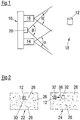
- Fig. 1 shows a system 10 for three-dimensional detection of an object 12.
- the system 10 comprises a first camera 14 and a second camera 16.
- the first camera 14 and the second camera 16 are directed to a scene 18 in which the object 12 is located.
- the scene 18 is detected by the first camera 14 from a different position than the second camera 16.
- the first camera 14 and the second camera 16 each have a viewing angle ⁇ , within which the scene 18 can be detected.
- a lighting device 20 is arranged, which emits laser light in the infrared range.
- the illumination device 20 radiates the laser light in an angular range ⁇ , which is greater than the angle ⁇ .
- the system 10 also includes a computing unit (not shown) that performs and monitors the operation of the system 10 discussed below.
- the illumination device 20 irradiates the scene 18 and thus also the object 12, while the first camera 14 and the second camera 16 capture images of the scene 18.
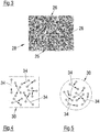
- FIG Fig. 2 A first image 22 captured by the first camera 14 and a second image 24 captured by the second camera 16 are shown in FIG Fig. 2 shown.
- the image of the object 12 can be seen approximately in the middle, whereas in the second image 24 the object 12 is correspondingly shifted further to the left. This shift in the images 22, 24 is caused by the offset position of the first camera 14 relative to the second camera 16.
- illumination points 26 can be seen, which are projected by the illumination device 20 into the scene 18.
- the illumination points 26 form a self-similar illumination pattern 28, which is described in more detail in FIG Fig. 3 is shown.
- illumination pattern 28 shows a two-dimensional array of illumination points 26 with different brightness.
- the illumination pattern 28 has in particular no periodic structure and no line pattern, but is - as mentioned -sunä Siemens.
- the object 12 is designated by the reference numeral 12 in both the scene 18 (i.e., the subject space) and the images 22, 24.
- the reference numeral 12 in the images 22, 24 refers to the respective image of the object 12 (ie to the image space of the first image 22 or the image space of the second image 24).
- a rectangular correlation window 30 is placed around the object 12 in the first image 22.
- a search window 32 located in the second image 24.
- Another search window 32 is drawn around the actual position of the object 12 in the second image 24.
- the correlation window 30 and the search windows 32 are basically constructed identically and more specifically in FIGS 4 and 5 shown. In the following, only one correlation window 30 will be discussed, but the statements apply correspondingly to the search windows 32.
- Fig. 4 shows a rectangular correlation window 30, within which a plurality of pairs of points 34 is drawn.
- the arrangement of the pairs of points 34 was adapted during the development of the system 10 by a plurality of iterations (according to the trial-and-error principle) to the illumination pattern 28, so that even very small objects 12 can be well recognized.
- a binarization scheme is used, which is defined by the point pairs 34.
- Each pair of points 34 has a "direction" indicated by an arrow for defining the binarization scheme, the direction determining the order of comparison of the pair of points. For example, if the point or pixel in the origin of the arrow is lighter than the point at the end of the arrow, then a one is generated for the comparison of this point pair 34 as a result. Otherwise, the result of the comparison is a zero.
- the result of the binarization scheme is in each case a result vector for the correlation window 30 and the search windows 32, which contains either a zero or a one for each pair comparison of each point pair 34, the value contained in the result vector being the result of the comparison of the respective pair of punk 34.
- Such a binarization scheme can be applied either to a rectangular correlation window 30, as in FIG Fig. 4 shown, or on a circular correlation window 30, as in Fig. 5 shown to be applied. It is also possible to use rectangular or quadratic correlation windows and search windows, in which, however, only those pixels are evaluated which are located within a circle radius from the respective window center point. The circle radius can result from the minimum object resolution in pixels.
- the Binarleitersschema is applied to the correlation window 30 by means of the point pairs 34 and thus calculated a result vector for the correlation window.
- each possible search window 32 is evaluated, that is, the same binarization scheme as for the correlation window 30 is applied to each search window 32. Accordingly, a separate result vector is calculated for each search window 32.
- the search window 32 whose result vector has the smallest Hamming distance to the result vector of the correlation window 30, is regarded as the search window corresponding to the correlation window, in which case it can be assumed with great probability that the object 12 can also be seen within this search window 32 ,
- the search window 32 corresponding to the correlation window 30 is therefore the left in FIG Fig. 2 shown search window 32, which contains the object 12.
- the distance of the object 12 from the system 10 in the scene 18 can be determined by means of a triangulation method and entered into a depth map. For further objects (not shown), the method can be repeated accordingly.
Landscapes
- Engineering & Computer Science (AREA)
- Physics & Mathematics (AREA)
- Theoretical Computer Science (AREA)
- Computer Vision & Pattern Recognition (AREA)
- General Physics & Mathematics (AREA)
- Multimedia (AREA)
- Artificial Intelligence (AREA)
- Optics & Photonics (AREA)
- Health & Medical Sciences (AREA)
- Computing Systems (AREA)
- Databases & Information Systems (AREA)
- Evolutionary Computation (AREA)
- General Health & Medical Sciences (AREA)
- Medical Informatics (AREA)
- Software Systems (AREA)
- Length Measuring Devices By Optical Means (AREA)
- Image Analysis (AREA)
- Image Processing (AREA)
Claims (13)
- Procédé de détection tridimensionnelle d'objets (12), dans lequel- on saisit une scène (18) au moyen d'un premier dispositif de saisie d'image (14), en générant une première image (22),- on saisit la scène (18) également au moyen d'un second dispositif de saisie d'image (16), en générant une seconde image (24),- on définit une fenêtre de corrélation (30) en tant qu'extrait de la première image (22),- on définit plusieurs fenêtres de recherche (32) en tant qu'extraits de la seconde image (24), différentes fenêtres de recherche (32) reproduisant différentes zones de la seconde image (24),- au moyen d'un procédé de corrélation, on détermine la fenêtre de recherche (32) qui correspond à la fenêtre de corrélation (30),dans lequel- lors du procédé de corrélation, on applique un schéma de binarisation sur la fenêtre de corrélation (30) et sur les fenêtres de recherche (32), dans lequel on compare les points respectifs d'au moins une paire de points (34) sélectionnée de façon aléatoire à l'intérieur de la fenêtre de corrélation (30) et à l'intérieur des fenêtres de recherche (32), et on forme un vecteur de résultat respectif pour la fenêtre de corrélation (30) et pour les fenêtres de recherche (32),- il se produit une corrélation du vecteur de résultat de la fenêtre de corrélation (30) et des vecteurs de résultat de la fenêtre de recherche (32) afin de déterminer la fenêtre de recherche (32) qui correspond à la fenêtre de corrélation (30),caractérisé en ce que- on sélectionne ladite au moins une paire de points (34) au moyen de plusieurs itérations, et on ré-sélectionne au moins une paire de points (34) de façon aléatoire pour chaque itération, et on utilise cette au moins une paire de points (34) pour le procédé de corrélation, qui obtient la meilleure association entre la fenêtre de corrélation (30) et les fenêtres de recherche (32) qui correspondent à la fenêtre de corrélation (30), eton illumine la scène (18) avec un motif (28) qui est au moins localement auto-dissemblable.
- Procédé selon la revendication 1,
caractérisé en ce que
avant de saisir la scène (18), on sélectionne ladite au moins une paire de points (34), la paire de points (34) étant identique pour chaque fenêtre (30, 32). - Procédé selon la revendication 1 ou 2,
caractérisé en ce que
on utilise plusieurs paires de points (34) qui sont réparties uniformément à l'intérieur de la fenêtre de corrélation (30). - Procédé selon l'une au moins des revendications précédentes,
caractérisé en ce que
on sélectionne au moins 128 paires de points (34). - Procédé selon l'une au moins des revendications précédentes,
caractérisé en ce que
on exécute les itérations en se basant sur une première image (22) et sur une seconde image (24) d'au moins une scène connue (18). - Procédé selon l'une au moins des revendications précédentes,
caractérisé en ce que
lors des itérations, on modifie également le motif d'illumination (28). - Procédé selon l'une au moins des revendications précédentes,
caractérisé en ce que
la fenêtre de corrélation (30) et les fenêtres de recherche (32) ont la même surface, la surface étant inférieure à 0,5 %, de préférence inférieure à 0,1 %, de manière particulièrement préférée inférieure à 0,01 % de la surface de la première et/ou de la seconde image (22, 24). - Procédé selon l'une au moins des revendications précédentes,
caractérisé en ce que
la fenêtre de corrélation (30) et les fenêtres de recherche (32) sont réalisées circulaires. - Procédé selon l'une au moins des revendications précédentes,
caractérisé en ce que
la corrélation du vecteur de résultat de la fenêtre de corrélation (30) et les vecteurs de résultat des fenêtres de recherche (32) s'effectue en se basant sur la distance Hamming des vecteurs de résultat. - Procédé selon la revendication 9,
caractérisé en ce que
on forme un agrégat de plusieurs distances Hamming, en particulier de 3 x 3 distances Hamming, et la corrélation s'effectue en se basant sur l'agrégat. - Procédé selon l'une au moins des revendications précédentes,
caractérisé en ce que
on rectifie la première et la seconde image (22, 24) et/ou on les filtre par un filtre de bruit. - Procédé selon l'une au moins des revendications précédentes,
caractérisé en ce que
on dispose les fenêtres de recherche (32) uniquement de long de la ligne épipolaire (36) de la seconde image (24). - Système (10) pour la détection tridimensionnelle d'objets (12), comportant un premier dispositif de saisie d'image (14), un second dispositif de saisie d'image (16) et une unité de calcul,
dans lequel
le système (10) est réalisé pour mettre en oeuvre un procédé selon l'une au moins des revendications précédentes.
Priority Applications (2)
| Application Number | Priority Date | Filing Date | Title |
|---|---|---|---|
| EP15184182.2A EP3142068B1 (fr) | 2015-09-08 | 2015-09-08 | Procede de detection tridimensionnelle d'objets |
| US15/258,033 US10007857B2 (en) | 2015-09-08 | 2016-09-07 | Method for the three-dimensional detection of objects |
Applications Claiming Priority (1)
| Application Number | Priority Date | Filing Date | Title |
|---|---|---|---|
| EP15184182.2A EP3142068B1 (fr) | 2015-09-08 | 2015-09-08 | Procede de detection tridimensionnelle d'objets |
Publications (2)
| Publication Number | Publication Date |
|---|---|
| EP3142068A1 EP3142068A1 (fr) | 2017-03-15 |
| EP3142068B1 true EP3142068B1 (fr) | 2018-01-03 |
Family
ID=54151078
Family Applications (1)
| Application Number | Title | Priority Date | Filing Date |
|---|---|---|---|
| EP15184182.2A Active EP3142068B1 (fr) | 2015-09-08 | 2015-09-08 | Procede de detection tridimensionnelle d'objets |
Country Status (2)
| Country | Link |
|---|---|
| US (1) | US10007857B2 (fr) |
| EP (1) | EP3142068B1 (fr) |
Families Citing this family (2)
| Publication number | Priority date | Publication date | Assignee | Title |
|---|---|---|---|---|
| EP3142068B1 (fr) * | 2015-09-08 | 2018-01-03 | Sick Ag | Procede de detection tridimensionnelle d'objets |
| CN115018850B (zh) * | 2022-08-09 | 2022-11-01 | 深圳市领拓实业有限公司 | 基于图像处理的精密电子零部件冲压孔毛刺检测方法 |
Family Cites Families (8)
| Publication number | Priority date | Publication date | Assignee | Title |
|---|---|---|---|---|
| US6215898B1 (en) | 1997-04-15 | 2001-04-10 | Interval Research Corporation | Data processing system and method |
| DE102006001634B3 (de) | 2006-01-11 | 2007-03-01 | Tropf, Hermann | Erstellung eines Abstandsbildes |
| DE502007001505D1 (de) | 2007-07-20 | 2009-10-22 | Sick Ag | Verfahren zum Betrieb eines 3D-Sensors |
| EP2166305B1 (fr) | 2008-09-23 | 2012-05-16 | Sick Ag | Unité d'éclairage et procédé de projection d'un motif d'éclairage |
| EP2166304A1 (fr) | 2008-09-23 | 2010-03-24 | Sick Ag | Unité d'éclairage et procédé de production d'un modèle auto-dissemblable |
| EP2772676B1 (fr) | 2011-05-18 | 2015-07-08 | Sick Ag | Caméra 3D et procédé de surveillance tridimensionnel d'un domaine de surveillance |
| US9098908B2 (en) * | 2011-10-21 | 2015-08-04 | Microsoft Technology Licensing, Llc | Generating a depth map |
| EP3142068B1 (fr) * | 2015-09-08 | 2018-01-03 | Sick Ag | Procede de detection tridimensionnelle d'objets |
-
2015
- 2015-09-08 EP EP15184182.2A patent/EP3142068B1/fr active Active
-
2016
- 2016-09-07 US US15/258,033 patent/US10007857B2/en active Active
Non-Patent Citations (1)
| Title |
|---|
| YLIOINAS JUHA ET AL: "Learning local image descriptors using binary decision trees", IEEE WINTER CONFERENCE ON APPLICATIONS OF COMPUTER VISION, IEEE, 24 March 2014 (2014-03-24), pages 347 - 354, XP032609970, DOI: 10.1109/WACV.2014.6836079 * |
Also Published As
| Publication number | Publication date |
|---|---|
| EP3142068A1 (fr) | 2017-03-15 |
| US20170068856A1 (en) | 2017-03-09 |
| US10007857B2 (en) | 2018-06-26 |
Similar Documents
| Publication | Publication Date | Title |
|---|---|---|
| DE2831582C2 (de) | Verfahren zur Identifizierung einer Person und Vorrichtung zur Durchführung des Verfahrens | |
| EP2584493B1 (fr) | Procédé de distinction entre un visage réel et une représentation bidimensionnelle du visage dans un processus d'enregistrement biométrique | |
| EP0780002B1 (fr) | Procede et appareil pour reconstruir de structures constituees de lignes sous forme d'une trame | |
| DE102007035884B4 (de) | Linienrauschunterdrückungsvorrichtung, -verfahren und -programm | |
| DE112007000371T5 (de) | Objekterkennungssystem und -Verfahren | |
| DE102013112040B4 (de) | System und Verfahren zum Auffinden von sattelpunktartigen Strukturen in einem Bild und Bestimmen von Informationen daraus | |
| DE102007051967A1 (de) | Detektor und Verfahren zum Erkennen einer Fahrspurbegrenzung | |
| DE102005025220B4 (de) | Gerät, Verfahren und Programm zum Beseitigen von Poren | |
| EP3142068B1 (fr) | Procede de detection tridimensionnelle d'objets | |
| EP3214602B1 (fr) | Procédé de détection tridimensionnelle d'objets | |
| EP4192645A1 (fr) | Procédé et machine-outil à banc plat pour détecter une position de suspension d'une entretoise d'appui | |
| DE10145608B4 (de) | Modellbasierte Objektklassifikation und Zielerkennung | |
| EP3655920B1 (fr) | Procédé et dispositif pour l'évaluation de sections d'images pour un calcul de correspondance | |
| EP3274652A1 (fr) | Procédé de projection en photogrammes, dispositif de projection en photogrammes et produit-programme informatique | |
| DE10027657A1 (de) | Verfahren zur Ermittlung von Referenzpunkten in einem Fingerabdruckbild | |
| DE102008059551A1 (de) | Verfahren zum Ermitteln der Lageänderung eines Kamerasystems und Vorrichtung zum Erfassen und Verarbeiten von Bildern | |
| DE102018006932A1 (de) | Bildverarbeitungseinrichtung und -programm | |
| WO2000028470A2 (fr) | Production d'une image d'une empreinte digitale deroulee a partir d'une serie d'images individuelles | |
| DE102017110533A1 (de) | Verfahren zum Kalibrieren eines optischen Messaufbaus | |
| DE10042387A1 (de) | Verfahren zum Transformieren dreidimensionaler Objektpunkte in zweidimensionale Bildpunkte für Linear-Fächerstrahlsensor-Bilder | |
| DE102018207411A1 (de) | Verfahren zur Ermittlung von Messinformationen in einem optischen Koordinatenmessgerät | |
| DE102018208604A1 (de) | Ermitteln eines Aufnahmeverhaltens einer Aufnahmeeinheit | |
| DE102012013079B4 (de) | Verfahren und Vorrichtung zum berührungslosen Erfassen einer dreidimensionalen Kontur | |
| DE102019100660B4 (de) | Verfahren zur Transformation zwischen Bildpunkten und Objektpunkten | |
| DE102008025213A1 (de) | Verfahren zur Segmentierung von Fingerabdruckbildern |
Legal Events
| Date | Code | Title | Description |
|---|---|---|---|
| PUAI | Public reference made under article 153(3) epc to a published international application that has entered the european phase |
Free format text: ORIGINAL CODE: 0009012 |
|
| 17P | Request for examination filed |
Effective date: 20160928 |
|
| AK | Designated contracting states |
Kind code of ref document: A1 Designated state(s): AL AT BE BG CH CY CZ DE DK EE ES FI FR GB GR HR HU IE IS IT LI LT LU LV MC MK MT NL NO PL PT RO RS SE SI SK SM TR |
|
| AX | Request for extension of the european patent |
Extension state: BA ME |
|
| REG | Reference to a national code |
Ref country code: DE Ref legal event code: R079 Ref document number: 502015002748 Country of ref document: DE Free format text: PREVIOUS MAIN CLASS: G06T0007000000 Ipc: G06T0007521000 |
|
| GRAP | Despatch of communication of intention to grant a patent |
Free format text: ORIGINAL CODE: EPIDOSNIGR1 |
|
| RIC1 | Information provided on ipc code assigned before grant |
Ipc: G06T 7/593 20170101ALI20170607BHEP Ipc: G06T 7/521 20170101AFI20170607BHEP |
|
| INTG | Intention to grant announced |
Effective date: 20170630 |
|
| GRAS | Grant fee paid |
Free format text: ORIGINAL CODE: EPIDOSNIGR3 |
|
| GRAA | (expected) grant |
Free format text: ORIGINAL CODE: 0009210 |
|
| AK | Designated contracting states |
Kind code of ref document: B1 Designated state(s): AL AT BE BG CH CY CZ DE DK EE ES FI FR GB GR HR HU IE IS IT LI LT LU LV MC MK MT NL NO PL PT RO RS SE SI SK SM TR |
|
| REG | Reference to a national code |
Ref country code: GB Ref legal event code: FG4D Free format text: NOT ENGLISH |
|
| REG | Reference to a national code |
Ref country code: CH Ref legal event code: EP Ref country code: AT Ref legal event code: REF Ref document number: 960935 Country of ref document: AT Kind code of ref document: T Effective date: 20180115 |
|
| REG | Reference to a national code |
Ref country code: IE Ref legal event code: FG4D Free format text: LANGUAGE OF EP DOCUMENT: GERMAN |
|
| REG | Reference to a national code |
Ref country code: DE Ref legal event code: R096 Ref document number: 502015002748 Country of ref document: DE |
|
| REG | Reference to a national code |
Ref country code: NL Ref legal event code: MP Effective date: 20180103 |
|
| REG | Reference to a national code |
Ref country code: LT Ref legal event code: MG4D |
|
| PG25 | Lapsed in a contracting state [announced via postgrant information from national office to epo] |
Ref country code: NL Free format text: LAPSE BECAUSE OF FAILURE TO SUBMIT A TRANSLATION OF THE DESCRIPTION OR TO PAY THE FEE WITHIN THE PRESCRIBED TIME-LIMIT Effective date: 20180103 |
|
| PG25 | Lapsed in a contracting state [announced via postgrant information from national office to epo] |
Ref country code: CY Free format text: LAPSE BECAUSE OF FAILURE TO SUBMIT A TRANSLATION OF THE DESCRIPTION OR TO PAY THE FEE WITHIN THE PRESCRIBED TIME-LIMIT Effective date: 20180103 Ref country code: LT Free format text: LAPSE BECAUSE OF FAILURE TO SUBMIT A TRANSLATION OF THE DESCRIPTION OR TO PAY THE FEE WITHIN THE PRESCRIBED TIME-LIMIT Effective date: 20180103 Ref country code: NO Free format text: LAPSE BECAUSE OF FAILURE TO SUBMIT A TRANSLATION OF THE DESCRIPTION OR TO PAY THE FEE WITHIN THE PRESCRIBED TIME-LIMIT Effective date: 20180403 Ref country code: ES Free format text: LAPSE BECAUSE OF FAILURE TO SUBMIT A TRANSLATION OF THE DESCRIPTION OR TO PAY THE FEE WITHIN THE PRESCRIBED TIME-LIMIT Effective date: 20180103 Ref country code: HR Free format text: LAPSE BECAUSE OF FAILURE TO SUBMIT A TRANSLATION OF THE DESCRIPTION OR TO PAY THE FEE WITHIN THE PRESCRIBED TIME-LIMIT Effective date: 20180103 Ref country code: FI Free format text: LAPSE BECAUSE OF FAILURE TO SUBMIT A TRANSLATION OF THE DESCRIPTION OR TO PAY THE FEE WITHIN THE PRESCRIBED TIME-LIMIT Effective date: 20180103 |
|
| PG25 | Lapsed in a contracting state [announced via postgrant information from national office to epo] |
Ref country code: LV Free format text: LAPSE BECAUSE OF FAILURE TO SUBMIT A TRANSLATION OF THE DESCRIPTION OR TO PAY THE FEE WITHIN THE PRESCRIBED TIME-LIMIT Effective date: 20180103 Ref country code: SE Free format text: LAPSE BECAUSE OF FAILURE TO SUBMIT A TRANSLATION OF THE DESCRIPTION OR TO PAY THE FEE WITHIN THE PRESCRIBED TIME-LIMIT Effective date: 20180103 Ref country code: GR Free format text: LAPSE BECAUSE OF FAILURE TO SUBMIT A TRANSLATION OF THE DESCRIPTION OR TO PAY THE FEE WITHIN THE PRESCRIBED TIME-LIMIT Effective date: 20180404 Ref country code: PL Free format text: LAPSE BECAUSE OF FAILURE TO SUBMIT A TRANSLATION OF THE DESCRIPTION OR TO PAY THE FEE WITHIN THE PRESCRIBED TIME-LIMIT Effective date: 20180103 Ref country code: IS Free format text: LAPSE BECAUSE OF FAILURE TO SUBMIT A TRANSLATION OF THE DESCRIPTION OR TO PAY THE FEE WITHIN THE PRESCRIBED TIME-LIMIT Effective date: 20180503 Ref country code: BG Free format text: LAPSE BECAUSE OF FAILURE TO SUBMIT A TRANSLATION OF THE DESCRIPTION OR TO PAY THE FEE WITHIN THE PRESCRIBED TIME-LIMIT Effective date: 20180403 Ref country code: RS Free format text: LAPSE BECAUSE OF FAILURE TO SUBMIT A TRANSLATION OF THE DESCRIPTION OR TO PAY THE FEE WITHIN THE PRESCRIBED TIME-LIMIT Effective date: 20180103 |
|
| REG | Reference to a national code |
Ref country code: FR Ref legal event code: PLFP Year of fee payment: 4 |
|
| PG25 | Lapsed in a contracting state [announced via postgrant information from national office to epo] |
Ref country code: MT Free format text: LAPSE BECAUSE OF FAILURE TO SUBMIT A TRANSLATION OF THE DESCRIPTION OR TO PAY THE FEE WITHIN THE PRESCRIBED TIME-LIMIT Effective date: 20180103 |
|
| REG | Reference to a national code |
Ref country code: DE Ref legal event code: R097 Ref document number: 502015002748 Country of ref document: DE |
|
| PG25 | Lapsed in a contracting state [announced via postgrant information from national office to epo] |
Ref country code: IT Free format text: LAPSE BECAUSE OF FAILURE TO SUBMIT A TRANSLATION OF THE DESCRIPTION OR TO PAY THE FEE WITHIN THE PRESCRIBED TIME-LIMIT Effective date: 20180103 Ref country code: AL Free format text: LAPSE BECAUSE OF FAILURE TO SUBMIT A TRANSLATION OF THE DESCRIPTION OR TO PAY THE FEE WITHIN THE PRESCRIBED TIME-LIMIT Effective date: 20180103 Ref country code: EE Free format text: LAPSE BECAUSE OF FAILURE TO SUBMIT A TRANSLATION OF THE DESCRIPTION OR TO PAY THE FEE WITHIN THE PRESCRIBED TIME-LIMIT Effective date: 20180103 |
|
| PLBE | No opposition filed within time limit |
Free format text: ORIGINAL CODE: 0009261 |
|
| STAA | Information on the status of an ep patent application or granted ep patent |
Free format text: STATUS: NO OPPOSITION FILED WITHIN TIME LIMIT |
|
| PG25 | Lapsed in a contracting state [announced via postgrant information from national office to epo] |
Ref country code: SK Free format text: LAPSE BECAUSE OF FAILURE TO SUBMIT A TRANSLATION OF THE DESCRIPTION OR TO PAY THE FEE WITHIN THE PRESCRIBED TIME-LIMIT Effective date: 20180103 Ref country code: SM Free format text: LAPSE BECAUSE OF FAILURE TO SUBMIT A TRANSLATION OF THE DESCRIPTION OR TO PAY THE FEE WITHIN THE PRESCRIBED TIME-LIMIT Effective date: 20180103 Ref country code: CZ Free format text: LAPSE BECAUSE OF FAILURE TO SUBMIT A TRANSLATION OF THE DESCRIPTION OR TO PAY THE FEE WITHIN THE PRESCRIBED TIME-LIMIT Effective date: 20180103 Ref country code: DK Free format text: LAPSE BECAUSE OF FAILURE TO SUBMIT A TRANSLATION OF THE DESCRIPTION OR TO PAY THE FEE WITHIN THE PRESCRIBED TIME-LIMIT Effective date: 20180103 |
|
| 26N | No opposition filed |
Effective date: 20181005 |
|
| PG25 | Lapsed in a contracting state [announced via postgrant information from national office to epo] |
Ref country code: SI Free format text: LAPSE BECAUSE OF FAILURE TO SUBMIT A TRANSLATION OF THE DESCRIPTION OR TO PAY THE FEE WITHIN THE PRESCRIBED TIME-LIMIT Effective date: 20180103 |
|
| PG25 | Lapsed in a contracting state [announced via postgrant information from national office to epo] |
Ref country code: MC Free format text: LAPSE BECAUSE OF FAILURE TO SUBMIT A TRANSLATION OF THE DESCRIPTION OR TO PAY THE FEE WITHIN THE PRESCRIBED TIME-LIMIT Effective date: 20180103 |
|
| REG | Reference to a national code |
Ref country code: BE Ref legal event code: MM Effective date: 20180930 |
|
| REG | Reference to a national code |
Ref country code: IE Ref legal event code: MM4A |
|
| PG25 | Lapsed in a contracting state [announced via postgrant information from national office to epo] |
Ref country code: LU Free format text: LAPSE BECAUSE OF NON-PAYMENT OF DUE FEES Effective date: 20180908 |
|
| PG25 | Lapsed in a contracting state [announced via postgrant information from national office to epo] |
Ref country code: IE Free format text: LAPSE BECAUSE OF NON-PAYMENT OF DUE FEES Effective date: 20180908 |
|
| PG25 | Lapsed in a contracting state [announced via postgrant information from national office to epo] |
Ref country code: BE Free format text: LAPSE BECAUSE OF NON-PAYMENT OF DUE FEES Effective date: 20180930 |
|
| PG25 | Lapsed in a contracting state [announced via postgrant information from national office to epo] |
Ref country code: TR Free format text: LAPSE BECAUSE OF FAILURE TO SUBMIT A TRANSLATION OF THE DESCRIPTION OR TO PAY THE FEE WITHIN THE PRESCRIBED TIME-LIMIT Effective date: 20180103 |
|
| PG25 | Lapsed in a contracting state [announced via postgrant information from national office to epo] |
Ref country code: PT Free format text: LAPSE BECAUSE OF FAILURE TO SUBMIT A TRANSLATION OF THE DESCRIPTION OR TO PAY THE FEE WITHIN THE PRESCRIBED TIME-LIMIT Effective date: 20180103 |
|
| PG25 | Lapsed in a contracting state [announced via postgrant information from national office to epo] |
Ref country code: RO Free format text: LAPSE BECAUSE OF FAILURE TO SUBMIT A TRANSLATION OF THE DESCRIPTION OR TO PAY THE FEE WITHIN THE PRESCRIBED TIME-LIMIT Effective date: 20180103 Ref country code: MK Free format text: LAPSE BECAUSE OF NON-PAYMENT OF DUE FEES Effective date: 20180103 Ref country code: HU Free format text: LAPSE BECAUSE OF FAILURE TO SUBMIT A TRANSLATION OF THE DESCRIPTION OR TO PAY THE FEE WITHIN THE PRESCRIBED TIME-LIMIT; INVALID AB INITIO Effective date: 20150908 |
|
| REG | Reference to a national code |
Ref country code: AT Ref legal event code: MM01 Ref document number: 960935 Country of ref document: AT Kind code of ref document: T Effective date: 20200908 |
|
| PG25 | Lapsed in a contracting state [announced via postgrant information from national office to epo] |
Ref country code: AT Free format text: LAPSE BECAUSE OF NON-PAYMENT OF DUE FEES Effective date: 20200908 |
|
| PGFP | Annual fee paid to national office [announced via postgrant information from national office to epo] |
Ref country code: GB Payment date: 20220927 Year of fee payment: 8 |
|
| PGFP | Annual fee paid to national office [announced via postgrant information from national office to epo] |
Ref country code: FR Payment date: 20220920 Year of fee payment: 8 |
|
| PGFP | Annual fee paid to national office [announced via postgrant information from national office to epo] |
Ref country code: CH Payment date: 20220928 Year of fee payment: 8 |
|
| PGFP | Annual fee paid to national office [announced via postgrant information from national office to epo] |
Ref country code: DE Payment date: 20230919 Year of fee payment: 9 |
|
| REG | Reference to a national code |
Ref country code: CH Ref legal event code: PL |