EP3654441A1 - Cell supervision circuit and battery pack - Google Patents
Cell supervision circuit and battery pack Download PDFInfo
- Publication number
- EP3654441A1 EP3654441A1 EP19275071.9A EP19275071A EP3654441A1 EP 3654441 A1 EP3654441 A1 EP 3654441A1 EP 19275071 A EP19275071 A EP 19275071A EP 3654441 A1 EP3654441 A1 EP 3654441A1
- Authority
- EP
- European Patent Office
- Prior art keywords
- metal plate
- elastic portion
- transfer unit
- cell supervision
- heat transfer
- Prior art date
- Legal status (The legal status is an assumption and is not a legal conclusion. Google has not performed a legal analysis and makes no representation as to the accuracy of the status listed.)
- Granted
Links
Images
Classifications
-
- H—ELECTRICITY
- H01—ELECTRIC ELEMENTS
- H01M—PROCESSES OR MEANS, e.g. BATTERIES, FOR THE DIRECT CONVERSION OF CHEMICAL ENERGY INTO ELECTRICAL ENERGY
- H01M10/00—Secondary cells; Manufacture thereof
- H01M10/42—Methods or arrangements for servicing or maintenance of secondary cells or secondary half-cells
- H01M10/425—Structural combination with electronic components, e.g. electronic circuits integrated to the outside of the casing
-
- H—ELECTRICITY
- H01—ELECTRIC ELEMENTS
- H01M—PROCESSES OR MEANS, e.g. BATTERIES, FOR THE DIRECT CONVERSION OF CHEMICAL ENERGY INTO ELECTRICAL ENERGY
- H01M10/00—Secondary cells; Manufacture thereof
- H01M10/60—Heating or cooling; Temperature control
- H01M10/61—Types of temperature control
- H01M10/613—Cooling or keeping cold
-
- H—ELECTRICITY
- H01—ELECTRIC ELEMENTS
- H01M—PROCESSES OR MEANS, e.g. BATTERIES, FOR THE DIRECT CONVERSION OF CHEMICAL ENERGY INTO ELECTRICAL ENERGY
- H01M50/00—Constructional details or processes of manufacture of the non-active parts of electrochemical cells other than fuel cells, e.g. hybrid cells
- H01M50/20—Mountings; Secondary casings or frames; Racks, modules or packs; Suspension devices; Shock absorbers; Transport or carrying devices; Holders
- H01M50/284—Mountings; Secondary casings or frames; Racks, modules or packs; Suspension devices; Shock absorbers; Transport or carrying devices; Holders with incorporated circuit boards, e.g. printed circuit boards [PCB]
-
- H—ELECTRICITY
- H01—ELECTRIC ELEMENTS
- H01M—PROCESSES OR MEANS, e.g. BATTERIES, FOR THE DIRECT CONVERSION OF CHEMICAL ENERGY INTO ELECTRICAL ENERGY
- H01M50/00—Constructional details or processes of manufacture of the non-active parts of electrochemical cells other than fuel cells, e.g. hybrid cells
- H01M50/20—Mountings; Secondary casings or frames; Racks, modules or packs; Suspension devices; Shock absorbers; Transport or carrying devices; Holders
- H01M50/284—Mountings; Secondary casings or frames; Racks, modules or packs; Suspension devices; Shock absorbers; Transport or carrying devices; Holders with incorporated circuit boards, e.g. printed circuit boards [PCB]
- H01M50/287—Fixing of circuit boards to lids or covers
-
- H—ELECTRICITY
- H01—ELECTRIC ELEMENTS
- H01M—PROCESSES OR MEANS, e.g. BATTERIES, FOR THE DIRECT CONVERSION OF CHEMICAL ENERGY INTO ELECTRICAL ENERGY
- H01M10/00—Secondary cells; Manufacture thereof
- H01M10/60—Heating or cooling; Temperature control
- H01M10/66—Heat-exchange relationships between the cells and other systems, e.g. central heating systems or fuel cells
- H01M10/667—Heat-exchange relationships between the cells and other systems, e.g. central heating systems or fuel cells the system being an electronic component, e.g. a CPU, an inverter or a capacitor
-
- H—ELECTRICITY
- H01—ELECTRIC ELEMENTS
- H01M—PROCESSES OR MEANS, e.g. BATTERIES, FOR THE DIRECT CONVERSION OF CHEMICAL ENERGY INTO ELECTRICAL ENERGY
- H01M50/00—Constructional details or processes of manufacture of the non-active parts of electrochemical cells other than fuel cells, e.g. hybrid cells
- H01M50/20—Mountings; Secondary casings or frames; Racks, modules or packs; Suspension devices; Shock absorbers; Transport or carrying devices; Holders
- H01M50/289—Mountings; Secondary casings or frames; Racks, modules or packs; Suspension devices; Shock absorbers; Transport or carrying devices; Holders characterised by spacing elements or positioning means within frames, racks or packs
- H01M50/291—Mountings; Secondary casings or frames; Racks, modules or packs; Suspension devices; Shock absorbers; Transport or carrying devices; Holders characterised by spacing elements or positioning means within frames, racks or packs characterised by their shape
-
- H—ELECTRICITY
- H01—ELECTRIC ELEMENTS
- H01M—PROCESSES OR MEANS, e.g. BATTERIES, FOR THE DIRECT CONVERSION OF CHEMICAL ENERGY INTO ELECTRICAL ENERGY
- H01M50/00—Constructional details or processes of manufacture of the non-active parts of electrochemical cells other than fuel cells, e.g. hybrid cells
- H01M50/50—Current conducting connections for cells or batteries
- H01M50/569—Constructional details of current conducting connections for detecting conditions inside cells or batteries, e.g. details of voltage sensing terminals
-
- H—ELECTRICITY
- H02—GENERATION; CONVERSION OR DISTRIBUTION OF ELECTRIC POWER
- H02J—ELECTRIC POWER NETWORKS; CIRCUIT ARRANGEMENTS OR SYSTEMS FOR SUPPLYING OR DISTRIBUTING ELECTRIC POWER; SYSTEMS FOR STORING ELECTRIC ENERGY
- H02J7/00—Circuit arrangements for charging or discharging batteries or for supplying loads from batteries
- H02J7/70—Circuit arrangements for charging or discharging batteries or for supplying loads from batteries characterised by the mechanical construction
-
- H—ELECTRICITY
- H02—GENERATION; CONVERSION OR DISTRIBUTION OF ELECTRIC POWER
- H02J—ELECTRIC POWER NETWORKS; CIRCUIT ARRANGEMENTS OR SYSTEMS FOR SUPPLYING OR DISTRIBUTING ELECTRIC POWER; SYSTEMS FOR STORING ELECTRIC ENERGY
- H02J7/00—Circuit arrangements for charging or discharging batteries or for supplying loads from batteries
- H02J7/80—Circuit arrangements for charging or discharging batteries or for supplying loads from batteries including monitoring or indicating arrangements
-
- H—ELECTRICITY
- H05—ELECTRIC TECHNIQUES NOT OTHERWISE PROVIDED FOR
- H05K—PRINTED CIRCUITS; CASINGS OR CONSTRUCTIONAL DETAILS OF ELECTRIC APPARATUS; MANUFACTURE OF ASSEMBLAGES OF ELECTRICAL COMPONENTS
- H05K1/00—Printed circuits
- H05K1/02—Details
- H05K1/0201—Thermal arrangements, e.g. for cooling, heating or preventing overheating
-
- Y—GENERAL TAGGING OF NEW TECHNOLOGICAL DEVELOPMENTS; GENERAL TAGGING OF CROSS-SECTIONAL TECHNOLOGIES SPANNING OVER SEVERAL SECTIONS OF THE IPC; TECHNICAL SUBJECTS COVERED BY FORMER USPC CROSS-REFERENCE ART COLLECTIONS [XRACs] AND DIGESTS
- Y02—TECHNOLOGIES OR APPLICATIONS FOR MITIGATION OR ADAPTATION AGAINST CLIMATE CHANGE
- Y02E—REDUCTION OF GREENHOUSE GAS [GHG] EMISSIONS, RELATED TO ENERGY GENERATION, TRANSMISSION OR DISTRIBUTION
- Y02E60/00—Enabling technologies; Technologies with a potential or indirect contribution to GHG emissions mitigation
- Y02E60/10—Energy storage using batteries
Definitions
- the disclosure relates to the technical field of power battery, and in particular, to a cell supervision circuit and a battery pack.
- a cell supervision circuit is a control system of a power battery. Some of the heating devices in the CSC generate a large amount of heat, which will cause heat concentration after continuous operation. If the cell supervision circuit is in high temperature for a long time, its performance may decrease, affecting the safety of the power battery.
- the CSC generally transfers heat to the external fixing plate through the heat transfer unit.
- the heat transfer unit and the external fixing plate are metal plates having large area. Since the flatness of the heat transfer unit and the external fixing plate are deviated due to the limited processing accuracy of the components, there is a gap in the heat dissipation interface after the heat transfer unit and the external fixing plate are rigidly connected. This leads to the problem of heat resistance instability generated when heat is transferred between the heat dissipation interfaces, affecting the heat dissipation effect of CSC.
- An object of the embodiment of the disclosure is to provide a cell supervision circuit and a battery pack, which are beneficial to solve the problem of heat resistance instability during heat dissipation using the heat dissipation device.
- An embodiment of the disclosure provides a cell supervision circuit comprising: a circuit board; a heat transfer unit including a metal plate disposed adjacent to the circuit board, wherein the heat transfer unit dissipates heat through the metal plate; and a fixing plate connected to the heat transfer unit, wherein the fixing plate includes a body portion and an elastic portion formed on the body portion, and the elastic portion is used for filling a gap between the metal plate and the fixing plate.
- the body portion of the fixing plate has a first surface and a second surface that are opposite to each other, the first surface is disposed adjacent to the metal plate, and the elastic portion is formed by being recessed from the body portion in a direction from the second surface to the first surface.
- notches are provided on both sides of the elastic portion, and the notches penetrates through the body portion.
- the elastic portion comprises two connecting members which are disposed to be spaced apart from each other, and the connecting member has one end which is hung with respect to the body portion.
- a groove is provided in the elastic portion, and the groove is formed by being recessed from the elastic portion in a direction from the first surface to the second surface.
- the number of the elastic portion is one or more, and the metal plate is fixedly connected with the elastic portion.
- the heat transfer unit further includes a backing plate for supporting the metal plate, a stepped groove is provided in the backing plate, and the metal plate is fitted into the stepped groove and is in contact with the elastic portion.
- two or more ribs are disposed to be spaced from each other on the backing plate to support the metal plate.
- a heat-conducting pad is further provided between the circuit board and the metal plate of the heat transfer unit.
- Another embodiment of the disclosure further provides a battery pack comprising any one of the cell supervision circuits as described above.
- the elastic portion is formed on the fixing plate connected with the heat transfer unit, and is brought into close contact with the metal plate for dissipating heat on the heat transfer unit to fill the gap between the metal plate and the fixing plate. Therefore, the problem of heat resistance instability during heat dissipation is solved, and the heat dissipation effect of the cell supervision circuit is improved.
- the battery pack according to the embodiment of the disclosure employs the cell supervision circuit as described above. Therefore, the safety and reliability of the battery pack is improved.
- the orientation terms appearing in the following description refer to the directions shown in the drawings, and are not intended to limit the specific structure of the disclosure.
- the terms “mount” and “connect” are to be understood broadly, for example, they may be fixed connection or detachable connection or integral connection; or may be direct connection or indirect connection.
- the specific meaning of the above terms in the disclosure may be understood by the skilled in the art based on the specific situation.
- the terms “first”, “second”, and the like are used for descriptive purposes only, and should not to be construed as indicating or implying relative importance or implicitly indicating the number of the involved technical features.
- features involving “first”, “second”, and the like may include at least one of the features, either explicitly or implicitly.
- the embodiment of the disclosure provides a cell supervision circuit, which comprises a circuit board 1, a heat transfer unit 2 and a fixing plate 3.
- the electronic components 11 are provided on the circuit board 1.
- the electronic components 11 will generate heat due to electric current passing therethrough during operation.
- the heat transfer unit 2 includes a metal plate 21 which is disposed adjacent to the circuit board 1.
- the heat transfer unit 2 dissipates heat through the metal plate 21.
- the fixing plate 3 is connected to the heat transfer unit 2.
- the fixing plate 3 includes a body portion 31 and an elastic portion 32 which is formed on the body portion 31, and the elastic portion 32 is used for filling a gap between the metal plate 21 and the fixing plate 3.
- the elastic portion 32 is provided on the fixing plate 3 connected with the heat transfer unit 2, and is brought into close contact with the metal plate 21 for dissipating heat on the heat transfer unit 2 to fill the gap between the metal plate 21 and the fixing plate 3. Therefore, the problem of heat resistance instability during heat dissipation is solved, and the heat dissipation effect of CSC is improved.
- the body portion 31 of the fixing plate 3 has a first surface a and a second surface b that are opposite to each other.
- the first surface a is disposed adjacent to the metal plate 21.
- the elastic portion 32 is formed by being recessed from the body portion 31 in a direction from the second surface b to the first surface a.
- the fixing plate 3 is connected to the heat transfer unit 2, while the elastic portion 32 is recessed toward the metal plate 21.
- the elastic portion 32 is compressible due to its own elasticity, so that the metal plate 21 is in close contact with the elastic portion 32, and the gap between the metal plate 21 and the fixing plate 3 is adaptively adjusted. Therefore, a stable heat dissipation interface is formed between the metal plate 21 and the fixing plate 3, and thus the problem of heat resistance instability caused by machining flatness error of the metal plate 21 and the elastic portion 32 is solved.
- notches 33 are provided on both sides of the elastic portion 32. Each of the notches 33 penetrates through the body portion 31. The notches 33 can release the stress of the elastic portion 32 and the body portion 31, thereby improving the elastic deformation ability of the elastic portion 32.
- the elastic portion 32 is stamped by the body portion 31, and its wall thickness, molding height, and compression deformation amount are designed and verified according to the specific application.
- the elastic portion 32 includes two connecting members 321 which are disposed to be spaced apart from each other.
- Each connecting member 321 has one end which is hung with respect to the body portion 31. Thereby, the elastic deformation capability of the elastic portion 32 is further improved.
- a groove 322 is provided in the elastic portion 32.
- the groove 322 is formed by being recessed from the elastic portion 32 in the direction from the first surface a to the second surface b.
- the elastic deformation energy of the elastic portion 32 can be absorbed, and thereby the rigidity and strength of the elastic portion 32 can be improved.
- the strength of the structure of the elastic portion 32 can be increased, and the contact area for dissipating heat between the elastic portion 32 and the metal plate 21 can be increased.
- the number of the elastic portions 32 may be one or more. When the length dimension of the fixing plate 3 is small, only one elastic portion 32 may be formed on the body portion 31, and when the length dimension of the fixing plate 3 is large, two or more elastic portions 32 may be formed to be spaced apart from each other on the body portion 31.
- the elastic portion 32 is stamped by the body portion 31, it is difficult to ensure its durability by the elasticity of the elastic portion 32 alone.
- the metal plate 21 is fixedly connected to the elastic portion 32.
- fasteners 211 such as press rivets may be provided on the metal plate 21, and the corresponding mounting holes 323 may be provided in the elastic portion 32, as shown in Figs. 2 and 3 .
- the metal plate 21 is fixedly connected with the elastic portion 32 by the engagement of the nuts with the press rivets 211 passing through the mounting holes 323.
- the metal plate 21 and the elastic portion 32 may be fixedly connected to each other by welding.
- the heat transfer unit 2 further includes a backing plate 22 for supporting the metal plate 21.
- a stepped groove 221 is provided in the backing plate 22.
- the metal plate 21 is fitted into the stepped groove 221 and comes into contact with the elastic portion 32.
- the backing plate 22 may be a non-metallic member such as a plastic member.
- the metal plate 21 and the backing plate 22 may be integrally formed by insert molding, or may be manufactured separately and then directly assembled.
- two or more ribs 222 may be disposed to be spaced apart from each other in the stepped groove 221 to support the metal plate 21.
- the ribs 222 may be provided corresponding to the interval between two adjacent elastic portions 32, so as not to affect the fixed connection between the metal plate 21 and the elastic portions 32.
- a heat-conducting pad 4 is further provided between the circuit board 1 and the metal plate 21 of the heat transfer unit 2.
- the heat-conducting pad 4 is made of elastic material such as, but not limited to, silica gel plate.
- the heat-conducting pad 4 can fill the gap between the circuit board 1 and the metal plate 21, and on the other hand, the heat-conducting pad 4 can rapidly transfer the heat generated by the heating devices 11 of the circuit board 1 to the metal plate 21, thereby improving the heat-conducting efficiency.
- the heat transfer unit 2 is respectively connected to the circuit board 1 and the fixing plate 3 via the backing plate 22.
- double-headed positioning posts 223 are provided on the backing plate 22.
- the double-headed positioning post 223 comprises a male end and a female end that are disposed coaxially.
- the male end has an external thread and is disposed toward the fixing plate 3, and the female end has an internal thread and is disposed toward the circuit board 1.
- the circuit board 1 is fixed to the backing plate 22 by engaging a screw with the female end
- the fixing plate 3 is fixed to the backing plate 22 by engaging a nut with the male end.
- the cell supervision circuit further includes a housing 5 connected to the circuit board 1, to prevent impurities such as dust from falling onto the circuit board 1.
- the embodiment of the disclosure also provides a battery pack, which comprises any one of the cell supervision circuits as described above, thereby solving the problem of heat dissipation of the local heat of the circuit board 1, and improving the safety and reliability of the battery pack.
Landscapes
- Chemical & Material Sciences (AREA)
- Chemical Kinetics & Catalysis (AREA)
- Electrochemistry (AREA)
- General Chemical & Material Sciences (AREA)
- Engineering & Computer Science (AREA)
- Manufacturing & Machinery (AREA)
- Microelectronics & Electronic Packaging (AREA)
- Battery Mounting, Suspending (AREA)
- Secondary Cells (AREA)
- Cooling Or The Like Of Electrical Apparatus (AREA)
Abstract
Description
- The disclosure relates to the technical field of power battery, and in particular, to a cell supervision circuit and a battery pack.
- A cell supervision circuit (CSC) is a control system of a power battery. Some of the heating devices in the CSC generate a large amount of heat, which will cause heat concentration after continuous operation. If the cell supervision circuit is in high temperature for a long time, its performance may decrease, affecting the safety of the power battery.
- Nowadays, the CSC generally transfers heat to the external fixing plate through the heat transfer unit. The heat transfer unit and the external fixing plate are metal plates having large area. Since the flatness of the heat transfer unit and the external fixing plate are deviated due to the limited processing accuracy of the components, there is a gap in the heat dissipation interface after the heat transfer unit and the external fixing plate are rigidly connected. This leads to the problem of heat resistance instability generated when heat is transferred between the heat dissipation interfaces, affecting the heat dissipation effect of CSC.
- An object of the embodiment of the disclosure is to provide a cell supervision circuit and a battery pack, which are beneficial to solve the problem of heat resistance instability during heat dissipation using the heat dissipation device.
- An embodiment of the disclosure provides a cell supervision circuit comprising: a circuit board; a heat transfer unit including a metal plate disposed adjacent to the circuit board, wherein the heat transfer unit dissipates heat through the metal plate; and a fixing plate connected to the heat transfer unit, wherein the fixing plate includes a body portion and an elastic portion formed on the body portion, and the elastic portion is used for filling a gap between the metal plate and the fixing plate.
- According to one aspect of the embodiment of the disclosure, the body portion of the fixing plate has a first surface and a second surface that are opposite to each other, the first surface is disposed adjacent to the metal plate, and the elastic portion is formed by being recessed from the body portion in a direction from the second surface to the first surface.
- According to one aspect of the embodiment of the disclosure, notches are provided on both sides of the elastic portion, and the notches penetrates through the body portion.
- According to one aspect of the embodiment of the disclosure, the elastic portion comprises two connecting members which are disposed to be spaced apart from each other, and the connecting member has one end which is hung with respect to the body portion.
- According to an aspect of the embodiment of the disclosure, a groove is provided in the elastic portion, and the groove is formed by being recessed from the elastic portion in a direction from the first surface to the second surface.
- According to one aspect of the embodiment of the disclosure, the number of the elastic portion is one or more, and the metal plate is fixedly connected with the elastic portion.
- According to one aspect of the embodiment of the disclosure, the heat transfer unit further includes a backing plate for supporting the metal plate, a stepped groove is provided in the backing plate, and the metal plate is fitted into the stepped groove and is in contact with the elastic portion.
- According to one aspect of the embodiment of the disclosure, two or more ribs are disposed to be spaced from each other on the backing plate to support the metal plate.
- According to one aspect of the embodiment of the disclosure, a heat-conducting pad is further provided between the circuit board and the metal plate of the heat transfer unit.
- Another embodiment of the disclosure further provides a battery pack comprising any one of the cell supervision circuits as described above.
- In the cell supervision circuit according to the embodiment of the disclosure, the elastic portion is formed on the fixing plate connected with the heat transfer unit, and is brought into close contact with the metal plate for dissipating heat on the heat transfer unit to fill the gap between the metal plate and the fixing plate. Therefore, the problem of heat resistance instability during heat dissipation is solved, and the heat dissipation effect of the cell supervision circuit is improved. In addition, the battery pack according to the embodiment of the disclosure employs the cell supervision circuit as described above. Therefore, the safety and reliability of the battery pack is improved.
- Features, advantages, and technical effects of the exemplary embodiments of the disclosure will be described below with reference to the drawings.
-
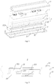
Fig. 1 shows a schematic structural view of a cell supervision circuit according to an embodiment of the disclosure; -
Fig. 2 shows a schematic structural view of a fixing plate of the cell supervision circuit shown inFig. 1 ; -
Fig. 3 shows a schematic structural view of another fixing plate of the cell supervision circuit shown inFig. 1 ; -
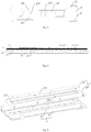
Fig. 4 shows a schematic view showing the assembling effect of the fixing plate and the heat transfer unit in the cell supervision circuit shown inFig. 1 ; -
Fig. 5 shows a schematic exploded view of the fixing plate and the heat transfer unit in the cell supervision circuit shown inFig. 4 . - In the drawings, the same reference numerals are used to indicate the same components. The drawings are not drawn to the actual scale.
- Features and exemplary embodiments according to various aspects of the disclosure are described in detail below. In the following detailed description, numerous specific details are set forth to provide comprehensive understanding of the disclosure. However, it will be apparent to the skilled in the art that the disclosure may be practiced without some of the specific details. The following description of the embodiments is merely to provide better understanding of the disclosure. In the figures and the following description, at least some of the known structures and techniques are not shown, to avoid unnecessarily obscuring the disclosure. Further, for clarity, the dimension of some of the structures may be enlarged. Furthermore, the features, structures, or characteristics described hereinafter may be combined in any suitable manner in one or more embodiments.
- The orientation terms appearing in the following description refer to the directions shown in the drawings, and are not intended to limit the specific structure of the disclosure. In the description of the disclosure, it should be noted that, unless otherwise stated, the terms "mount" and "connect" are to be understood broadly, for example, they may be fixed connection or detachable connection or integral connection; or may be direct connection or indirect connection. The specific meaning of the above terms in the disclosure may be understood by the skilled in the art based on the specific situation. Moreover, the terms "first", "second", and the like are used for descriptive purposes only, and should not to be construed as indicating or implying relative importance or implicitly indicating the number of the involved technical features. Thus, features involving "first", "second", and the like may include at least one of the features, either explicitly or implicitly.
- In order for better understanding of the disclosure, the cell supervision circuit and the battery pack according to embodiments of the disclosure will be described in detail with reference to
Figs. 1 to 5 . - The embodiment of the disclosure provides a cell supervision circuit, which comprises a circuit board 1, a
heat transfer unit 2 and afixing plate 3. - The
electronic components 11 are provided on the circuit board 1. Theelectronic components 11 will generate heat due to electric current passing therethrough during operation. Theheat transfer unit 2 includes ametal plate 21 which is disposed adjacent to the circuit board 1. Theheat transfer unit 2 dissipates heat through themetal plate 21. Thefixing plate 3 is connected to theheat transfer unit 2. Thefixing plate 3 includes abody portion 31 and anelastic portion 32 which is formed on thebody portion 31, and theelastic portion 32 is used for filling a gap between themetal plate 21 and thefixing plate 3. - In the cell supervision circuit according to the embodiment of the disclosure, the
elastic portion 32 is provided on thefixing plate 3 connected with theheat transfer unit 2, and is brought into close contact with themetal plate 21 for dissipating heat on theheat transfer unit 2 to fill the gap between themetal plate 21 and thefixing plate 3. Therefore, the problem of heat resistance instability during heat dissipation is solved, and the heat dissipation effect of CSC is improved. - The specific structure of the CSC according to the embodiment of the disclosure is described in further detail below with reference to the accompanying drawings.
- Referring to
Fig. 2 , thebody portion 31 of thefixing plate 3 has a first surface a and a second surface b that are opposite to each other. The first surface a is disposed adjacent to themetal plate 21. Theelastic portion 32 is formed by being recessed from thebody portion 31 in a direction from the second surface b to the first surface a. - The
fixing plate 3 is connected to theheat transfer unit 2, while theelastic portion 32 is recessed toward themetal plate 21. Theelastic portion 32 is compressible due to its own elasticity, so that themetal plate 21 is in close contact with theelastic portion 32, and the gap between themetal plate 21 and thefixing plate 3 is adaptively adjusted. Therefore, a stable heat dissipation interface is formed between themetal plate 21 and thefixing plate 3, and thus the problem of heat resistance instability caused by machining flatness error of themetal plate 21 and theelastic portion 32 is solved. - Furthermore,
notches 33 are provided on both sides of theelastic portion 32. Each of thenotches 33 penetrates through thebody portion 31. Thenotches 33 can release the stress of theelastic portion 32 and thebody portion 31, thereby improving the elastic deformation ability of theelastic portion 32. Theelastic portion 32 is stamped by thebody portion 31, and its wall thickness, molding height, and compression deformation amount are designed and verified according to the specific application. - Furthermore, the
elastic portion 32 includes two connectingmembers 321 which are disposed to be spaced apart from each other. Each connectingmember 321 has one end which is hung with respect to thebody portion 31. Thereby, the elastic deformation capability of theelastic portion 32 is further improved. - Referring to
Fig. 3 , agroove 322 is provided in theelastic portion 32. Thegroove 322 is formed by being recessed from theelastic portion 32 in the direction from the first surface a to the second surface b. By providing thegroove 322 whose recessed direction is opposite to that of theelastic portion 32, the elastic deformation energy of theelastic portion 32 can be absorbed, and thereby the rigidity and strength of theelastic portion 32 can be improved. As compared with the structure of theelastic portion 32 shown inFig. 2 , the strength of the structure of theelastic portion 32 can be increased, and the contact area for dissipating heat between theelastic portion 32 and themetal plate 21 can be increased. - The number of the
elastic portions 32 may be one or more. When the length dimension of the fixingplate 3 is small, only oneelastic portion 32 may be formed on thebody portion 31, and when the length dimension of the fixingplate 3 is large, two or moreelastic portions 32 may be formed to be spaced apart from each other on thebody portion 31. - Referring to
Fig. 4 , since theelastic portion 32 is stamped by thebody portion 31, it is difficult to ensure its durability by the elasticity of theelastic portion 32 alone. In order to improve the reliability of theelastic portion 32, themetal plate 21 is fixedly connected to theelastic portion 32. - Specifically,
fasteners 211 such as press rivets may be provided on themetal plate 21, and the corresponding mountingholes 323 may be provided in theelastic portion 32, as shown inFigs. 2 and3 . Themetal plate 21 is fixedly connected with theelastic portion 32 by the engagement of the nuts with the press rivets 211 passing through the mounting holes 323. Themetal plate 21 and theelastic portion 32 may be fixedly connected to each other by welding. - Referring to
Fig. 5 , in order to achieve a reliable connection between themetal plate 21 and theelastic portion 32, theheat transfer unit 2 further includes abacking plate 22 for supporting themetal plate 21. A steppedgroove 221 is provided in thebacking plate 22. Themetal plate 21 is fitted into the steppedgroove 221 and comes into contact with theelastic portion 32. Thebacking plate 22 may be a non-metallic member such as a plastic member. Themetal plate 21 and thebacking plate 22 may be integrally formed by insert molding, or may be manufactured separately and then directly assembled. - When the length of the
metal plate 21 is long, two ormore ribs 222 may be disposed to be spaced apart from each other in the steppedgroove 221 to support themetal plate 21. Preferably, theribs 222 may be provided corresponding to the interval between two adjacentelastic portions 32, so as not to affect the fixed connection between themetal plate 21 and theelastic portions 32. - Referring again to
Fig. 1 , in order to stabilize the heat dissipation interface between the circuit board 1 and themetal plate 21, a heat-conducting pad 4 is further provided between the circuit board 1 and themetal plate 21 of theheat transfer unit 2. The heat-conducting pad 4 is made of elastic material such as, but not limited to, silica gel plate. On one hand, the heat-conducting pad 4 can fill the gap between the circuit board 1 and themetal plate 21, and on the other hand, the heat-conducting pad 4 can rapidly transfer the heat generated by theheating devices 11 of the circuit board 1 to themetal plate 21, thereby improving the heat-conducting efficiency. - The
heat transfer unit 2 is respectively connected to the circuit board 1 and the fixingplate 3 via thebacking plate 22. Specifically, double-headedpositioning posts 223 are provided on thebacking plate 22. The double-headedpositioning post 223 comprises a male end and a female end that are disposed coaxially. The male end has an external thread and is disposed toward the fixingplate 3, and the female end has an internal thread and is disposed toward the circuit board 1. The circuit board 1 is fixed to thebacking plate 22 by engaging a screw with the female end, and the fixingplate 3 is fixed to thebacking plate 22 by engaging a nut with the male end. - The cell supervision circuit further includes a housing 5 connected to the circuit board 1, to prevent impurities such as dust from falling onto the circuit board 1.
- In addition, the embodiment of the disclosure also provides a battery pack, which comprises any one of the cell supervision circuits as described above, thereby solving the problem of heat dissipation of the local heat of the circuit board 1, and improving the safety and reliability of the battery pack.
- Although the disclosure has been described with reference to the above preferred embodiments, various modifications may be made thereto and the components therein may be replaced with equivalents without departing from the scope of the disclosure. In particular, each technical feature mentioned in the various embodiments may be combined in any manner as long as there is no structural conflict. The disclosure is not limited to the specific embodiments disclosed herein, but includes all technical solutions falling within the scope of the claims.
-
- 1
- circuit board
- 11
- electronic component
- 2
- heat transfer unit
- 21
- metal plate
- 211
- press rivets
- 22
- backing plate
- 221
- stepped groove
- 222
- rib
- 223
- double-headed fastener
- 3
- fixing plate
- 31
- body portion
- 32
- elastic portion
- a
- first surface
- b
- second surface
- 321
- connecting member
- 322
- groove
- 323
- mounting hole
- 33
- notch
- 4
- heat-conducting pad
- 5
- housing
Claims (10)
- A cell supervision circuit, characterized in comprising:a circuit board (1);a heat transfer unit (2) including a metal plate (21) disposed adjacent to the circuit board (1), wherein the heat transfer unit (2) dissipates heat through the metal plate (21); anda fixing plate (3) connected to the heat transfer unit (2), wherein the fixing plate (3) includes a body portion (31) and an elastic portion (32) formed on the body portion (31), and the elastic portion (32) is used for filling a gap between the metal plate (21) and the fixing plate (3).
- The cell supervision circuit according to claim 1, characterized in that the body portion (31) of the fixing plate (3) has a surface (a) and a second surface (b) that are opposite to each other, the first surface (a) is disposed adjacent to the metal plate (21), and the elastic portion (32) is formed by being recessed from the body portion (31) in a direction from the second surface (b) to the first surface (a).
- The cell supervision circuit according to claim 2, characterized in that notches (33) are provided on both sides of the elastic portion (32), and the notches (33) penetrates through the body portion (31).
- The cell supervision circuit according to claim 3, characterized in that the elastic portion (32) comprises two connecting members (321) which are disposed to be spaced apart from each other, each connecting member (321) has one end which is hung with respect to the main body (31).
- The cell supervision circuit according to claim 3, characterized in that a groove (322) is provided in the elastic portion (32), and the groove (322) is formed by being recessed from the elastic portion (32) in a direction from the first surface (a) to the second surface (b).
- The cell supervision circuit according to any one of claims 1 to 5, characterized in that the number of the elastic portion (32) is one or more, and the metal plate (21) is fixedly connected to the elastic portion (32).
- The cell supervision circuit according to claim 6, characterized in that the heat transfer unit (2) further includes a backing plate (22) for supporting the metal plate (21), a stepped groove (221) is provided in the backing plate (22), and the metal plate (21) is fitted into the stepped groove (221) and is in contact with the elastic portion (32).
- The cell supervision circuit according to claim 7, characterized in that two or more ribs (222) are provided in the stepped groove (221) to support the metal plate (21).
- The cell supervision circuit according to claim 1, characterized in that a heat-conducting pad (4) is further provided between the circuit board (1) and the metal plate (21) of the heat transfer unit (2).
- A battery pack, characterized in comprising a cell supervision circuit according to any one of claims 1 to 9.
Applications Claiming Priority (1)
| Application Number | Priority Date | Filing Date | Title |
|---|---|---|---|
| CN201821895875.2U CN209071559U (en) | 2018-11-15 | 2018-11-15 | Battery monitoring unit and battery pack |
Publications (2)
| Publication Number | Publication Date |
|---|---|
| EP3654441A1 true EP3654441A1 (en) | 2020-05-20 |
| EP3654441B1 EP3654441B1 (en) | 2021-09-15 |
Family
ID=66677084
Family Applications (1)
| Application Number | Title | Priority Date | Filing Date |
|---|---|---|---|
| EP19275071.9A Active EP3654441B1 (en) | 2018-11-15 | 2019-05-30 | Cell supervision circuit and battery pack |
Country Status (4)
| Country | Link |
|---|---|
| US (1) | US11050109B2 (en) |
| EP (1) | EP3654441B1 (en) |
| CN (1) | CN209071559U (en) |
| WO (1) | WO2020098764A1 (en) |
Families Citing this family (4)
| Publication number | Priority date | Publication date | Assignee | Title |
|---|---|---|---|---|
| CN209071559U (en) | 2018-11-15 | 2019-07-05 | 宁德时代新能源科技股份有限公司 | Battery monitoring unit and battery pack |
| DE102020105614B4 (en) * | 2020-03-03 | 2024-03-21 | Dr. Ing. H.C. F. Porsche Aktiengesellschaft | Battery arrangement for an electrically powered motor vehicle |
| CN113889713B (en) | 2020-07-03 | 2024-10-25 | 莫仕连接器(成都)有限公司 | Battery connection module |
| KR102755060B1 (en) * | 2020-10-29 | 2025-01-20 | 주식회사 엘지에너지솔루션 | Battery pack including a protection circuit module heat radiation structure using heat radiation tape |
Citations (13)
| Publication number | Priority date | Publication date | Assignee | Title |
|---|---|---|---|---|
| CN2686088Y (en) * | 2003-12-25 | 2005-03-16 | 曜越科技股份有限公司 | Heat dissipation component buckle with integrally formed elastic components |
| US20060169507A1 (en) * | 2005-02-02 | 2006-08-03 | Denso Corporation | Cooling structure of heat generating member |
| US20070153483A1 (en) * | 2005-12-30 | 2007-07-05 | Ati Technologies Inc. | Thermal management device for multiple heat producing devices |
| US7626821B1 (en) * | 2006-12-12 | 2009-12-01 | Nvidia Corporation | Adaptor for graphics module |
| CN102522510A (en) * | 2011-12-02 | 2012-06-27 | 苏州冠硕新能源有限公司 | Battery system |
| CN103176563A (en) * | 2011-12-20 | 2013-06-26 | 鸿富锦精密工业(深圳)有限公司 | Electronic device |
| DE202012012655U1 (en) * | 2012-08-09 | 2013-12-03 | Robert Bosch Gmbh | Housing for a battery cell with a housing cover having a monitoring electronics, battery cell, battery module and motor vehicle |
| CN204792925U (en) * | 2015-05-18 | 2015-11-18 | 储盈新能源科技(上海)有限公司 | Novel battery box and novel battery |
| CN204906846U (en) * | 2015-08-27 | 2015-12-23 | 深圳市吉瑞达电路科技有限公司 | Dustproof heat dissipation type PCB circuit plate structure |
| US20160143158A1 (en) * | 2013-03-19 | 2016-05-19 | Yoshinori WAKANA (deceased) | Electronic Control Device |
| CN206116553U (en) * | 2016-08-30 | 2017-04-19 | 深圳市航盛电子股份有限公司 | Battery management system heat abstractor |
| CN108093599A (en) * | 2016-11-22 | 2018-05-29 | 讯凯国际股份有限公司 | Heat sink device |
| US20180261900A1 (en) * | 2017-03-10 | 2018-09-13 | Samsung Electronics Co., Ltd. | Battery including heat dissipation plate and electronic device having the same |
Family Cites Families (17)
| Publication number | Priority date | Publication date | Assignee | Title |
|---|---|---|---|---|
| US6175688B1 (en) * | 1998-07-10 | 2001-01-16 | Belmont Instrument Corporation | Wearable intravenous fluid heater |
| DE50310865D1 (en) * | 2002-03-14 | 2009-01-15 | Beurer Gmbh & Co | HEATING DEVICE WITH FLEXIBLE RADIATOR |
| US8398209B2 (en) * | 2009-11-12 | 2013-03-19 | Godex International Co., Ltd. | Integrated structure of a printer head and an antenna |
| CN103038567A (en) * | 2010-04-16 | 2013-04-10 | 弗莱克斯照明第二有限责任公司 | Illumination device comprising a film-based lightguide |
| KR101210088B1 (en) * | 2010-07-29 | 2012-12-07 | 삼성에스디아이 주식회사 | Protection circuit module including thermistor and battery pack with same |
| DE102012001440A1 (en) * | 2012-01-26 | 2013-08-01 | Li-Tec Battery Gmbh | An electrochemical energy conversion device having a cell housing, a battery having at least two of these electrochemical energy conversion devices, and methods for producing an electrochemical energy conversion device. |
| EP2807687A2 (en) * | 2012-01-26 | 2014-12-03 | Li-Tec Battery GmbH | Electrochemical energy conversion device comprising a cell housing, battery comprising at least two of said electrochemical energy conversion devices, and method for the production of an electrochemical energy conversion device |
| EP2824014B1 (en) * | 2013-07-08 | 2015-10-21 | Fagor, S. Coop. | Electric drive device |
| JP6349731B2 (en) * | 2014-01-08 | 2018-07-04 | 株式会社デンソー | Circuit board structure |
| CN105449401B (en) * | 2014-08-08 | 2019-02-05 | 莫列斯公司 | Electrical connector and electrical connector combination |
| KR102415651B1 (en) * | 2015-07-01 | 2022-07-01 | 엘지전자 주식회사 | Mobile terminal |
| CN205406596U (en) | 2016-02-26 | 2016-07-27 | 成都雅骏新能源汽车科技股份有限公司 | CSC subassembly fixed bolster and install battery box of CSC subassembly |
| CN206379400U (en) | 2016-12-30 | 2017-08-04 | 宁德时代新能源科技股份有限公司 | Battery mounting bracket |
| US10321606B2 (en) * | 2017-03-28 | 2019-06-11 | Intel Corporation | Flexible thermally-conductive shunt |
| CN207719292U (en) | 2018-01-19 | 2018-08-10 | 宁德时代新能源科技股份有限公司 | Battery monitoring unit mounting bracket, battery pack and automobile |
| US11569553B2 (en) * | 2018-06-06 | 2023-01-31 | Samsung Sdi Co., Ltd. | Battery system configured to detect abnormal battery system conditions and method of the same |
| CN209071559U (en) | 2018-11-15 | 2019-07-05 | 宁德时代新能源科技股份有限公司 | Battery monitoring unit and battery pack |
-
2018
- 2018-11-15 CN CN201821895875.2U patent/CN209071559U/en active Active
-
2019
- 2019-05-24 US US16/422,863 patent/US11050109B2/en active Active
- 2019-05-30 EP EP19275071.9A patent/EP3654441B1/en active Active
- 2019-11-15 WO PCT/CN2019/118666 patent/WO2020098764A1/en not_active Ceased
Patent Citations (13)
| Publication number | Priority date | Publication date | Assignee | Title |
|---|---|---|---|---|
| CN2686088Y (en) * | 2003-12-25 | 2005-03-16 | 曜越科技股份有限公司 | Heat dissipation component buckle with integrally formed elastic components |
| US20060169507A1 (en) * | 2005-02-02 | 2006-08-03 | Denso Corporation | Cooling structure of heat generating member |
| US20070153483A1 (en) * | 2005-12-30 | 2007-07-05 | Ati Technologies Inc. | Thermal management device for multiple heat producing devices |
| US7626821B1 (en) * | 2006-12-12 | 2009-12-01 | Nvidia Corporation | Adaptor for graphics module |
| CN102522510A (en) * | 2011-12-02 | 2012-06-27 | 苏州冠硕新能源有限公司 | Battery system |
| CN103176563A (en) * | 2011-12-20 | 2013-06-26 | 鸿富锦精密工业(深圳)有限公司 | Electronic device |
| DE202012012655U1 (en) * | 2012-08-09 | 2013-12-03 | Robert Bosch Gmbh | Housing for a battery cell with a housing cover having a monitoring electronics, battery cell, battery module and motor vehicle |
| US20160143158A1 (en) * | 2013-03-19 | 2016-05-19 | Yoshinori WAKANA (deceased) | Electronic Control Device |
| CN204792925U (en) * | 2015-05-18 | 2015-11-18 | 储盈新能源科技(上海)有限公司 | Novel battery box and novel battery |
| CN204906846U (en) * | 2015-08-27 | 2015-12-23 | 深圳市吉瑞达电路科技有限公司 | Dustproof heat dissipation type PCB circuit plate structure |
| CN206116553U (en) * | 2016-08-30 | 2017-04-19 | 深圳市航盛电子股份有限公司 | Battery management system heat abstractor |
| CN108093599A (en) * | 2016-11-22 | 2018-05-29 | 讯凯国际股份有限公司 | Heat sink device |
| US20180261900A1 (en) * | 2017-03-10 | 2018-09-13 | Samsung Electronics Co., Ltd. | Battery including heat dissipation plate and electronic device having the same |
Also Published As
| Publication number | Publication date |
|---|---|
| CN209071559U (en) | 2019-07-05 |
| WO2020098764A1 (en) | 2020-05-22 |
| US11050109B2 (en) | 2021-06-29 |
| EP3654441B1 (en) | 2021-09-15 |
| US20200161605A1 (en) | 2020-05-21 |
Similar Documents
| Publication | Publication Date | Title |
|---|---|---|
| US11050109B2 (en) | Cell supervision circuit and battery pack | |
| US11088418B2 (en) | Battery module | |
| US20220217865A1 (en) | Circuit structure | |
| EP3644696A1 (en) | Floating-type heat sink and elastic bracket therefor | |
| CN214125853U (en) | Power module heat radiation structure | |
| CN211184790U (en) | Electric bicycle lithium cell heat radiation structure | |
| CN109066005B (en) | A liquid-cooled battery module with elastic support structure | |
| CN207282486U (en) | A kind of fixed structure, controller and the electric car of controller metal-oxide-semiconductor | |
| CN209608536U (en) | Power inverter | |
| CN218039659U (en) | A copper bar fixing device and battery | |
| WO2025097758A1 (en) | Collection assembly and battery pack | |
| CN217822993U (en) | Battery and battery device | |
| CN211580297U (en) | Fastening device for a power structure | |
| CN118610639A (en) | A battery core frame assembly, battery module, energy storage device and electrical equipment | |
| CN212378919U (en) | Temperature sensor device and temperature sensor mounting structure | |
| CN210328388U (en) | Power device cooling components | |
| CN113054310A (en) | Battery package and consumer | |
| CN222547815U (en) | Auxiliary clamping structure, circuit board assembly and electronic equipment | |
| CN214545322U (en) | A heat dissipation structure of a high-power power supply | |
| CN224165016U (en) | In-vehicle electronic equipment | |
| CN222546345U (en) | Heat dissipation structure, power single tube installation structure and electronic equipment | |
| CN219067022U (en) | a battery pack | |
| CN220731183U (en) | Heat sinks, heat dissipation structures and solid state drive components | |
| CN220673641U (en) | Inverter and air conditioner | |
| CN217158316U (en) | Battery cell heat dissipation device and battery cell test system |
Legal Events
| Date | Code | Title | Description |
|---|---|---|---|
| PUAI | Public reference made under article 153(3) epc to a published international application that has entered the european phase |
Free format text: ORIGINAL CODE: 0009012 |
|
| STAA | Information on the status of an ep patent application or granted ep patent |
Free format text: STATUS: REQUEST FOR EXAMINATION WAS MADE |
|
| 17P | Request for examination filed |
Effective date: 20200331 |
|
| AK | Designated contracting states |
Kind code of ref document: A1 Designated state(s): AL AT BE BG CH CY CZ DE DK EE ES FI FR GB GR HR HU IE IS IT LI LT LU LV MC MK MT NL NO PL PT RO RS SE SI SK SM TR |
|
| AX | Request for extension of the european patent |
Extension state: BA ME |
|
| STAA | Information on the status of an ep patent application or granted ep patent |
Free format text: STATUS: EXAMINATION IS IN PROGRESS |
|
| 17Q | First examination report despatched |
Effective date: 20200810 |
|
| RIC1 | Information provided on ipc code assigned before grant |
Ipc: H05K 1/02 20060101ALI20210326BHEP Ipc: H01M 10/42 20060101AFI20210326BHEP |
|
| GRAP | Despatch of communication of intention to grant a patent |
Free format text: ORIGINAL CODE: EPIDOSNIGR1 |
|
| STAA | Information on the status of an ep patent application or granted ep patent |
Free format text: STATUS: GRANT OF PATENT IS INTENDED |
|
| INTG | Intention to grant announced |
Effective date: 20210511 |
|
| GRAS | Grant fee paid |
Free format text: ORIGINAL CODE: EPIDOSNIGR3 |
|
| GRAA | (expected) grant |
Free format text: ORIGINAL CODE: 0009210 |
|
| STAA | Information on the status of an ep patent application or granted ep patent |
Free format text: STATUS: THE PATENT HAS BEEN GRANTED |
|
| AK | Designated contracting states |
Kind code of ref document: B1 Designated state(s): AL AT BE BG CH CY CZ DE DK EE ES FI FR GB GR HR HU IE IS IT LI LT LU LV MC MK MT NL NO PL PT RO RS SE SI SK SM TR |
|
| REG | Reference to a national code |
Ref country code: CH Ref legal event code: EP |
|
| REG | Reference to a national code |
Ref country code: DE Ref legal event code: R096 Ref document number: 602019007728 Country of ref document: DE |
|
| REG | Reference to a national code |
Ref country code: IE Ref legal event code: FG4D |
|
| REG | Reference to a national code |
Ref country code: AT Ref legal event code: REF Ref document number: 1431231 Country of ref document: AT Kind code of ref document: T Effective date: 20211015 |
|
| REG | Reference to a national code |
Ref country code: LT Ref legal event code: MG9D |
|
| REG | Reference to a national code |
Ref country code: NL Ref legal event code: MP Effective date: 20210915 |
|
| PG25 | Lapsed in a contracting state [announced via postgrant information from national office to epo] |
Ref country code: LT Free format text: LAPSE BECAUSE OF FAILURE TO SUBMIT A TRANSLATION OF THE DESCRIPTION OR TO PAY THE FEE WITHIN THE PRESCRIBED TIME-LIMIT Effective date: 20210915 Ref country code: BG Free format text: LAPSE BECAUSE OF FAILURE TO SUBMIT A TRANSLATION OF THE DESCRIPTION OR TO PAY THE FEE WITHIN THE PRESCRIBED TIME-LIMIT Effective date: 20211215 Ref country code: NO Free format text: LAPSE BECAUSE OF FAILURE TO SUBMIT A TRANSLATION OF THE DESCRIPTION OR TO PAY THE FEE WITHIN THE PRESCRIBED TIME-LIMIT Effective date: 20211215 Ref country code: HR Free format text: LAPSE BECAUSE OF FAILURE TO SUBMIT A TRANSLATION OF THE DESCRIPTION OR TO PAY THE FEE WITHIN THE PRESCRIBED TIME-LIMIT Effective date: 20210915 Ref country code: FI Free format text: LAPSE BECAUSE OF FAILURE TO SUBMIT A TRANSLATION OF THE DESCRIPTION OR TO PAY THE FEE WITHIN THE PRESCRIBED TIME-LIMIT Effective date: 20210915 Ref country code: SE Free format text: LAPSE BECAUSE OF FAILURE TO SUBMIT A TRANSLATION OF THE DESCRIPTION OR TO PAY THE FEE WITHIN THE PRESCRIBED TIME-LIMIT Effective date: 20210915 Ref country code: RS Free format text: LAPSE BECAUSE OF FAILURE TO SUBMIT A TRANSLATION OF THE DESCRIPTION OR TO PAY THE FEE WITHIN THE PRESCRIBED TIME-LIMIT Effective date: 20210915 |
|
| REG | Reference to a national code |
Ref country code: AT Ref legal event code: MK05 Ref document number: 1431231 Country of ref document: AT Kind code of ref document: T Effective date: 20210915 |
|
| PG25 | Lapsed in a contracting state [announced via postgrant information from national office to epo] |
Ref country code: LV Free format text: LAPSE BECAUSE OF FAILURE TO SUBMIT A TRANSLATION OF THE DESCRIPTION OR TO PAY THE FEE WITHIN THE PRESCRIBED TIME-LIMIT Effective date: 20210915 Ref country code: GR Free format text: LAPSE BECAUSE OF FAILURE TO SUBMIT A TRANSLATION OF THE DESCRIPTION OR TO PAY THE FEE WITHIN THE PRESCRIBED TIME-LIMIT Effective date: 20211216 |
|
| PG25 | Lapsed in a contracting state [announced via postgrant information from national office to epo] |
Ref country code: AT Free format text: LAPSE BECAUSE OF FAILURE TO SUBMIT A TRANSLATION OF THE DESCRIPTION OR TO PAY THE FEE WITHIN THE PRESCRIBED TIME-LIMIT Effective date: 20210915 |
|
| PG25 | Lapsed in a contracting state [announced via postgrant information from national office to epo] |
Ref country code: IS Free format text: LAPSE BECAUSE OF FAILURE TO SUBMIT A TRANSLATION OF THE DESCRIPTION OR TO PAY THE FEE WITHIN THE PRESCRIBED TIME-LIMIT Effective date: 20220115 Ref country code: SM Free format text: LAPSE BECAUSE OF FAILURE TO SUBMIT A TRANSLATION OF THE DESCRIPTION OR TO PAY THE FEE WITHIN THE PRESCRIBED TIME-LIMIT Effective date: 20210915 Ref country code: SK Free format text: LAPSE BECAUSE OF FAILURE TO SUBMIT A TRANSLATION OF THE DESCRIPTION OR TO PAY THE FEE WITHIN THE PRESCRIBED TIME-LIMIT Effective date: 20210915 Ref country code: RO Free format text: LAPSE BECAUSE OF FAILURE TO SUBMIT A TRANSLATION OF THE DESCRIPTION OR TO PAY THE FEE WITHIN THE PRESCRIBED TIME-LIMIT Effective date: 20210915 Ref country code: PT Free format text: LAPSE BECAUSE OF FAILURE TO SUBMIT A TRANSLATION OF THE DESCRIPTION OR TO PAY THE FEE WITHIN THE PRESCRIBED TIME-LIMIT Effective date: 20220117 Ref country code: PL Free format text: LAPSE BECAUSE OF FAILURE TO SUBMIT A TRANSLATION OF THE DESCRIPTION OR TO PAY THE FEE WITHIN THE PRESCRIBED TIME-LIMIT Effective date: 20210915 Ref country code: NL Free format text: LAPSE BECAUSE OF FAILURE TO SUBMIT A TRANSLATION OF THE DESCRIPTION OR TO PAY THE FEE WITHIN THE PRESCRIBED TIME-LIMIT Effective date: 20210915 Ref country code: ES Free format text: LAPSE BECAUSE OF FAILURE TO SUBMIT A TRANSLATION OF THE DESCRIPTION OR TO PAY THE FEE WITHIN THE PRESCRIBED TIME-LIMIT Effective date: 20210915 Ref country code: EE Free format text: LAPSE BECAUSE OF FAILURE TO SUBMIT A TRANSLATION OF THE DESCRIPTION OR TO PAY THE FEE WITHIN THE PRESCRIBED TIME-LIMIT Effective date: 20210915 Ref country code: CZ Free format text: LAPSE BECAUSE OF FAILURE TO SUBMIT A TRANSLATION OF THE DESCRIPTION OR TO PAY THE FEE WITHIN THE PRESCRIBED TIME-LIMIT Effective date: 20210915 Ref country code: AL Free format text: LAPSE BECAUSE OF FAILURE TO SUBMIT A TRANSLATION OF THE DESCRIPTION OR TO PAY THE FEE WITHIN THE PRESCRIBED TIME-LIMIT Effective date: 20210915 |
|
| REG | Reference to a national code |
Ref country code: DE Ref legal event code: R097 Ref document number: 602019007728 Country of ref document: DE |
|
| PLBE | No opposition filed within time limit |
Free format text: ORIGINAL CODE: 0009261 |
|
| STAA | Information on the status of an ep patent application or granted ep patent |
Free format text: STATUS: NO OPPOSITION FILED WITHIN TIME LIMIT |
|
| PG25 | Lapsed in a contracting state [announced via postgrant information from national office to epo] |
Ref country code: DK Free format text: LAPSE BECAUSE OF FAILURE TO SUBMIT A TRANSLATION OF THE DESCRIPTION OR TO PAY THE FEE WITHIN THE PRESCRIBED TIME-LIMIT Effective date: 20210915 |
|
| 26N | No opposition filed |
Effective date: 20220616 |
|
| PG25 | Lapsed in a contracting state [announced via postgrant information from national office to epo] |
Ref country code: SI Free format text: LAPSE BECAUSE OF FAILURE TO SUBMIT A TRANSLATION OF THE DESCRIPTION OR TO PAY THE FEE WITHIN THE PRESCRIBED TIME-LIMIT Effective date: 20210915 |
|
| REG | Reference to a national code |
Ref country code: CH Ref legal event code: PL |
|
| REG | Reference to a national code |
Ref country code: BE Ref legal event code: MM Effective date: 20220531 |
|
| PG25 | Lapsed in a contracting state [announced via postgrant information from national office to epo] |
Ref country code: MC Free format text: LAPSE BECAUSE OF FAILURE TO SUBMIT A TRANSLATION OF THE DESCRIPTION OR TO PAY THE FEE WITHIN THE PRESCRIBED TIME-LIMIT Effective date: 20210915 Ref country code: LU Free format text: LAPSE BECAUSE OF NON-PAYMENT OF DUE FEES Effective date: 20220530 Ref country code: LI Free format text: LAPSE BECAUSE OF NON-PAYMENT OF DUE FEES Effective date: 20220531 Ref country code: IT Free format text: LAPSE BECAUSE OF FAILURE TO SUBMIT A TRANSLATION OF THE DESCRIPTION OR TO PAY THE FEE WITHIN THE PRESCRIBED TIME-LIMIT Effective date: 20210915 Ref country code: CH Free format text: LAPSE BECAUSE OF NON-PAYMENT OF DUE FEES Effective date: 20220531 |
|
| PG25 | Lapsed in a contracting state [announced via postgrant information from national office to epo] |
Ref country code: IE Free format text: LAPSE BECAUSE OF NON-PAYMENT OF DUE FEES Effective date: 20220530 |
|
| PG25 | Lapsed in a contracting state [announced via postgrant information from national office to epo] |
Ref country code: BE Free format text: LAPSE BECAUSE OF NON-PAYMENT OF DUE FEES Effective date: 20220531 |
|
| P01 | Opt-out of the competence of the unified patent court (upc) registered |
Effective date: 20230516 |
|
| PG25 | Lapsed in a contracting state [announced via postgrant information from national office to epo] |
Ref country code: MK Free format text: LAPSE BECAUSE OF FAILURE TO SUBMIT A TRANSLATION OF THE DESCRIPTION OR TO PAY THE FEE WITHIN THE PRESCRIBED TIME-LIMIT Effective date: 20210915 Ref country code: CY Free format text: LAPSE BECAUSE OF FAILURE TO SUBMIT A TRANSLATION OF THE DESCRIPTION OR TO PAY THE FEE WITHIN THE PRESCRIBED TIME-LIMIT Effective date: 20210915 |
|
| PG25 | Lapsed in a contracting state [announced via postgrant information from national office to epo] |
Ref country code: HU Free format text: LAPSE BECAUSE OF FAILURE TO SUBMIT A TRANSLATION OF THE DESCRIPTION OR TO PAY THE FEE WITHIN THE PRESCRIBED TIME-LIMIT; INVALID AB INITIO Effective date: 20190530 |
|
| REG | Reference to a national code |
Ref country code: DE Ref legal event code: R081 Ref document number: 602019007728 Country of ref document: DE Owner name: CONTEMPORARY AMPEREX TECHNOLOGY (HONG KONG) LI, HK Free format text: FORMER OWNER: CONTEMPORARY AMPEREX TECHNOLOGY CO., LIMITED, NINGDE CITY, FUJIAN, CN |
|
| REG | Reference to a national code |
Ref country code: GB Ref legal event code: 732E Free format text: REGISTERED BETWEEN 20240808 AND 20240814 |
|
| PG25 | Lapsed in a contracting state [announced via postgrant information from national office to epo] |
Ref country code: MT Free format text: LAPSE BECAUSE OF FAILURE TO SUBMIT A TRANSLATION OF THE DESCRIPTION OR TO PAY THE FEE WITHIN THE PRESCRIBED TIME-LIMIT Effective date: 20210915 |
|
| PG25 | Lapsed in a contracting state [announced via postgrant information from national office to epo] |
Ref country code: TR Free format text: LAPSE BECAUSE OF FAILURE TO SUBMIT A TRANSLATION OF THE DESCRIPTION OR TO PAY THE FEE WITHIN THE PRESCRIBED TIME-LIMIT Effective date: 20210915 |
|
| PGFP | Annual fee paid to national office [announced via postgrant information from national office to epo] |
Ref country code: GB Payment date: 20260310 Year of fee payment: 8 |
|
| PGFP | Annual fee paid to national office [announced via postgrant information from national office to epo] |
Ref country code: DE Payment date: 20260331 Year of fee payment: 8 |
|
| PGFP | Annual fee paid to national office [announced via postgrant information from national office to epo] |
Ref country code: FR Payment date: 20260401 Year of fee payment: 8 |