JP6349731B2 - Circuit board structure - Google Patents
Circuit board structure Download PDFInfo
- Publication number
- JP6349731B2 JP6349731B2 JP2014001626A JP2014001626A JP6349731B2 JP 6349731 B2 JP6349731 B2 JP 6349731B2 JP 2014001626 A JP2014001626 A JP 2014001626A JP 2014001626 A JP2014001626 A JP 2014001626A JP 6349731 B2 JP6349731 B2 JP 6349731B2
- Authority
- JP
- Japan
- Prior art keywords
- battery
- circuit board
- heat transfer
- heating element
- transfer member
- Prior art date
- Legal status (The legal status is an assumption and is not a legal conclusion. Google has not performed a legal analysis and makes no representation as to the accuracy of the status listed.)
- Active
Links
Images


Classifications
-
- H—ELECTRICITY
- H01—ELECTRIC ELEMENTS
- H01M—PROCESSES OR MEANS, e.g. BATTERIES, FOR THE DIRECT CONVERSION OF CHEMICAL ENERGY INTO ELECTRICAL ENERGY
- H01M10/00—Secondary cells; Manufacture thereof
- H01M10/42—Methods or arrangements for servicing or maintenance of secondary cells or secondary half-cells
- H01M10/425—Structural combination with electronic components, e.g. electronic circuits integrated to the outside of the casing
-
- H—ELECTRICITY
- H01—ELECTRIC ELEMENTS
- H01M—PROCESSES OR MEANS, e.g. BATTERIES, FOR THE DIRECT CONVERSION OF CHEMICAL ENERGY INTO ELECTRICAL ENERGY
- H01M10/00—Secondary cells; Manufacture thereof
- H01M10/60—Heating or cooling; Temperature control
- H01M10/61—Types of temperature control
- H01M10/615—Heating or keeping warm
-
- H—ELECTRICITY
- H01—ELECTRIC ELEMENTS
- H01M—PROCESSES OR MEANS, e.g. BATTERIES, FOR THE DIRECT CONVERSION OF CHEMICAL ENERGY INTO ELECTRICAL ENERGY
- H01M10/00—Secondary cells; Manufacture thereof
- H01M10/60—Heating or cooling; Temperature control
- H01M10/62—Heating or cooling; Temperature control specially adapted for specific applications
- H01M10/625—Vehicles
-
- H—ELECTRICITY
- H01—ELECTRIC ELEMENTS
- H01M—PROCESSES OR MEANS, e.g. BATTERIES, FOR THE DIRECT CONVERSION OF CHEMICAL ENERGY INTO ELECTRICAL ENERGY
- H01M10/00—Secondary cells; Manufacture thereof
- H01M10/60—Heating or cooling; Temperature control
- H01M10/64—Heating or cooling; Temperature control characterised by the shape of the cells
- H01M10/643—Cylindrical cells
-
- H—ELECTRICITY
- H01—ELECTRIC ELEMENTS
- H01M—PROCESSES OR MEANS, e.g. BATTERIES, FOR THE DIRECT CONVERSION OF CHEMICAL ENERGY INTO ELECTRICAL ENERGY
- H01M10/00—Secondary cells; Manufacture thereof
- H01M10/60—Heating or cooling; Temperature control
- H01M10/65—Means for temperature control structurally associated with the cells
- H01M10/655—Solid structures for heat exchange or heat conduction
- H01M10/6554—Rods or plates
-
- H—ELECTRICITY
- H01—ELECTRIC ELEMENTS
- H01M—PROCESSES OR MEANS, e.g. BATTERIES, FOR THE DIRECT CONVERSION OF CHEMICAL ENERGY INTO ELECTRICAL ENERGY
- H01M10/00—Secondary cells; Manufacture thereof
- H01M10/60—Heating or cooling; Temperature control
- H01M10/65—Means for temperature control structurally associated with the cells
- H01M10/657—Means for temperature control structurally associated with the cells by electric or electromagnetic means
- H01M10/6571—Resistive heaters
-
- H—ELECTRICITY
- H01—ELECTRIC ELEMENTS
- H01M—PROCESSES OR MEANS, e.g. BATTERIES, FOR THE DIRECT CONVERSION OF CHEMICAL ENERGY INTO ELECTRICAL ENERGY
- H01M50/00—Constructional details or processes of manufacture of the non-active parts of electrochemical cells other than fuel cells, e.g. hybrid cells
- H01M50/20—Mountings; Secondary casings or frames; Racks, modules or packs; Suspension devices; Shock absorbers; Transport or carrying devices; Holders
- H01M50/204—Racks, modules or packs for multiple batteries or multiple cells
- H01M50/207—Racks, modules or packs for multiple batteries or multiple cells characterised by their shape
- H01M50/213—Racks, modules or packs for multiple batteries or multiple cells characterised by their shape adapted for cells having curved cross-section, e.g. round or elliptic
-
- H—ELECTRICITY
- H01—ELECTRIC ELEMENTS
- H01M—PROCESSES OR MEANS, e.g. BATTERIES, FOR THE DIRECT CONVERSION OF CHEMICAL ENERGY INTO ELECTRICAL ENERGY
- H01M10/00—Secondary cells; Manufacture thereof
- H01M10/42—Methods or arrangements for servicing or maintenance of secondary cells or secondary half-cells
- H01M10/48—Accumulators combined with arrangements for measuring, testing or indicating the condition of cells, e.g. the level or density of the electrolyte
- H01M10/486—Accumulators combined with arrangements for measuring, testing or indicating the condition of cells, e.g. the level or density of the electrolyte for measuring temperature
-
- H—ELECTRICITY
- H01—ELECTRIC ELEMENTS
- H01M—PROCESSES OR MEANS, e.g. BATTERIES, FOR THE DIRECT CONVERSION OF CHEMICAL ENERGY INTO ELECTRICAL ENERGY
- H01M2220/00—Batteries for particular applications
- H01M2220/20—Batteries in motive systems, e.g. vehicle, ship, plane
-
- Y—GENERAL TAGGING OF NEW TECHNOLOGICAL DEVELOPMENTS; GENERAL TAGGING OF CROSS-SECTIONAL TECHNOLOGIES SPANNING OVER SEVERAL SECTIONS OF THE IPC; TECHNICAL SUBJECTS COVERED BY FORMER USPC CROSS-REFERENCE ART COLLECTIONS [XRACs] AND DIGESTS
- Y02—TECHNOLOGIES OR APPLICATIONS FOR MITIGATION OR ADAPTATION AGAINST CLIMATE CHANGE
- Y02E—REDUCTION OF GREENHOUSE GAS [GHG] EMISSIONS, RELATED TO ENERGY GENERATION, TRANSMISSION OR DISTRIBUTION
- Y02E60/00—Enabling technologies; Technologies with a potential or indirect contribution to GHG emissions mitigation
- Y02E60/10—Energy storage using batteries
Description
本発明は、回路基板上に、電池が搭載される回路基板構造に関する。 The present invention relates to a circuit board structure in which a battery is mounted on a circuit board.
車両に搭載されるバッテリは、低温環境下では出力能力が低下するため、ヒータを用いてバッテリを加熱する構成が提案されている。例えば特許文献1では、可撓性ペット樹脂基板1にクシ形電極2を形成し、クシ形電極2の上に樹脂系PTC発熱体を塗布形成することで、面状の発熱体を形成する。そして、その面状発熱体を車両に搭載されるバッテリの四側面外周に巻回し、クシ形電極2に通電して前記バッテリを加熱している。
Since a battery mounted on a vehicle has a low output capability in a low temperature environment, a configuration in which the battery is heated using a heater has been proposed. For example, in
ところで、近年車両には、事故発生時等に緊急通報を行うための緊急通報装置が搭載されることがある。この緊急通報装置は、車両に搭載されているバッテリが損傷した場合でも通報を実行可能とするため、予備電源として小型の電池を装置内部に備えている。このような予備電源用の電池も、やはり低温環境下で出力能力が低下するので、ヒータを用いて加熱する構成を採用するのが望ましい。 By the way, in recent years, an emergency call device for making an emergency call in the event of an accident may be mounted on a vehicle. This emergency call device is equipped with a small battery as a backup power source in order to be able to execute a call even when a battery mounted on the vehicle is damaged. Such a battery for a standby power supply also has a low output capability in a low temperature environment, so it is desirable to employ a configuration in which the battery is heated using a heater.
しかしながら、このような緊急通報装置が内蔵する電池に、特許文献1と同様の構成を適用することを想定すると、以下のような問題がある。電池の外周を面状発熱体で覆うとすれば、電池に例えば面状発熱体をテープ等により固定することでパック化して一体の構成にせざるを得ず、つまりモジュール化する必要がある。すると、そのモジュールがカスタム品となるため、市場での流動量が多い汎用的な電池の採用ができなくなり、コストの低下を妨げるおそれがある。また、電池が消耗した際に交換する場合も、発熱体も含むモジュールごと交換することになる。したがって、交換時のコストも上昇してしまう。
However, assuming that the same configuration as that of
本発明は上記事情に鑑みてなされたものであり、その目的は、電池の採用や交換にコストを要することなく電池を加熱できる回路基板構造を提供することにある。 The present invention has been made in view of the above circumstances, and an object of the present invention is to provide a circuit board structure capable of heating a battery without requiring a cost for adopting or replacing the battery.
請求項1から4記載の回路基板構造によれば、回路基板上に電池と発熱体とを搭載し、発熱体が発した熱を電池に伝達する伝熱部材を備える。そして、電池を、伝熱部材を介して回路基板上に着脱可能に固定する。このように構成すれば、発熱体が発した熱を伝熱部材を介して電池に伝導させて電池を加熱できると共に、必要に応じて電池を伝熱部材より着脱して容易に交換することができる。
また、請求項1及び2記載の回路基板構造によれば、伝熱部材は、回路基板に固定されると共に、電池を保持する形状の電池保持部を有して構成される金属製の電池保持体と、回路基板と電池保持体及び電池との間に介挿され、弾性を有するシート状の伝熱材とを有している。
また、請求項3及び4記載の回路基板構造によれば、伝熱部材は、回路基板に固定されると共に、電池を保持する形状の電池保持部を有し、且つ弾性を有する部材からなる電池保持体で構成されている。
更に、請求項1及び3記載の回路基板構造によれば、電池保持体は、一端側が回路基板に固定され、他端側に電池保持部を有する形状に構成され、電池が、電池保持部へと押圧された状態で保持される。
更にまた、請求項2及び4記載の回路基板構造によれば、電池保持体は、両端側が回路基板に固定され、その両端の間に電池保持部を有する形状に構成されている。
According to the circuit board structure of the first to fourth aspects, the battery and the heating element are mounted on the circuit board, and the heat transfer member that transmits heat generated by the heating element to the battery is provided. Then, the battery is detachably fixed on the circuit board via the heat transfer member. If comprised in this way, while the heat | fever which the heat generating body emitted can be conducted to a battery through a heat-transfer member, a battery can be heated, a battery can be easily attached or detached from a heat-transfer member as needed. it can.
According to the circuit board structure of
According to the circuit board structure of
Furthermore, according to the circuit board structure according to
Furthermore, according to the circuit board structure of the second and fourth aspects, the battery holding body is configured in such a shape that both ends are fixed to the circuit board and the battery holding portion is provided between the both ends.
請求項5記載の回路基板構造によれば、発熱体を回路基板の一方の面側に配置し、伝熱部材を回路基板の他方の面側に配置する。そして、回路基板における発熱体が配置されている部分と伝熱部材が配置されている部分とに対応する位置にスルーホールを形成し、そのスルーホールを介して発熱体から伝熱部材への熱伝導を行う。このように構成すれば、発熱体と伝熱部材とを回路基板の両面にコンパクトに配置できると共に、両者間の熱伝導をスルーホールを介して行うことで、熱の伝達効率も良好に維持できる。 According to the circuit board structure of the fifth aspect, the heating element is arranged on one surface side of the circuit board, and the heat transfer member is arranged on the other surface side of the circuit board. Then, a through hole is formed at a position corresponding to the portion where the heating element is arranged on the circuit board and the portion where the heat transfer member is arranged, and the heat from the heating element to the heat transfer member via the through hole is formed. Conduct. If comprised in this way, while being able to arrange | position a heat generating body and a heat-transfer member compactly on both surfaces of a circuit board, heat transfer efficiency can also be maintained favorable by performing heat conduction between both via a through hole. .
請求項6記載の回路基板構造によれば、発熱体をチップ抵抗で構成するので、チップ抵抗のサイズや配置数を調整することで、電池の加熱態様を簡単に調整できる。
請求項7記載の回路基板構造によれば、電池が円筒状の外形を有する際に、発熱体を電池の外形の長手方向に沿うように配置する。したがって、電池を効率的に加熱することができる。
According to the circuit board structure of the sixth aspect , since the heating element is constituted by the chip resistor, the heating mode of the battery can be easily adjusted by adjusting the size and number of the chip resistors.
According to the circuit board structure of the seventh aspect , when the battery has a cylindrical outer shape, the heating element is arranged along the longitudinal direction of the outer shape of the battery. Therefore, the battery can be efficiently heated.
(第1実施形態)
図2に示すように、車載用緊急通報装置1(電子機器)は、車両に搭載可能であり、信号検出部2と、制御回路3(制御手段)と、緊急通報通信回路4とを備える。尚、車両に搭載可能とは、車両に対して固定状態で搭載されている態様、及び車両に対して着脱可能に搭載されている態様の何れも含む。
(First embodiment)
As shown in FIG. 2, the in-vehicle emergency call device 1 (electronic device) can be mounted on a vehicle, and includes a
衝突センサ5は、車両ボデーの例えば車両前方部等の所定部位に設けられ、車両が衝突したことを受けて車両の衝突に反応すると、センサ信号を通報用信号出力部6に出力する。通報用信号出力部6は、例えばエアバッグECU(Electronic Control Unit)であり、衝突センサ5からセンサ信号が入力されない期間では、通常信号をパルス信号により信号検出部2に出力する。一方、通報用信号出力部6は、衝突センサ5からセンサ信号が入力されると、通常信号とは異なる通報用信号をパルス信号により信号検出部2に出力すると共に、エアバッグ(図示せず)の展開制御を行い、運転者や同乗者を衝突の衝撃から防御する。
The
信号検出部2は、通報用信号出力部6から入力されるパルス信号を検出し、そのパルス信号のレベルがハイ,ロー間で変化するエッジの間隔(ハイ,ローパルス継続期間)等を検出し、その検出結果を特定可能な検出信号を制御回路3に出力する。車両側に搭載されているバッテリである主バッテリ7は、車載用緊急通報装置1に動作用電源を供給する。尚、車載用緊急通報装置1内における電源系の構成については後述する図1で説明する。
The
制御回路3は、CPU、ROM、RAM等からなるマイクロコンピュータを主体として構成され、ROMに格納されている動作プログラムを実行し、車載用緊急通報装置1の動作全般を制御する。制御回路3は、IG(イグニッション)やACC(アクセサリ)がオフ状態では、車両スイッチ8からのIG信号やACC信号の入力を低消費電力状態で監視しており、IG信号やACC信号の入力を判定することで、IGやACCのオフ状態からオン状態への切換を判定する。
The
また、制御回路3は、信号検出部2から検出信号が入力されると、その検出信号を解析することで、通報用信号出力部6が出力したパルス信号が通報用信号であるか通常信号であるか、即ち、車両が衝突したか否かを判定する。制御回路3は、通報用信号出力部6が出力したパルス信号が通報用信号であり、即ち、車両が衝突したと判定すると、緊急通報の実行指示を緊急通報通信回路4に出力する。
Further, when a detection signal is input from the
緊急通報通信回路4は、電話機能(通信網へ発信する発信機能、通信網から着信する着信機能、音声通話を行う音声通話機能、及びデータ通信を行うデータ通信機能等)を有し、制御回路3から緊急通報の実行指示が入力されると、その電話機能を用いた緊急通報を行う。具体的には、緊急通報通信回路4は、例えばGPS測位を用いて現在位置特定部(図示せず)により特定された車両の現在位置や、車両を特定可能な予め登録されている車両識別情報(車両番号、車両の使用者等)を含む緊急通報信号を、予め登録されている外部機関のセンター装置9に広域通信網(移動通信網及び固定通信網を含む)を介して送信することで、緊急通報を行う。
The emergency
センター装置9は、車載用緊急通報装置1から送信された緊急通報信号を広域通信網を介して受信すると、緊急通報の発生を外部機関のオペレータ等に報知する。オペレータは、これ以降、救援要請を受けて必要な援助を行う。オペレータとユーザ(運転者)との間で行われる援助の形態は様々である。例えば、車載用緊急通報装置1がセンター装置9に発信(発呼)して電話回線を接続し、車載用緊急通報装置1が上記した車両の現在位置や車両識別情報をセンター装置9に送信した後に電話回線を一旦切断し、センター装置9が車載用緊急通報装置1に発信(コールバック)して電話回線を再接続し、音声通話を行っても良いし、電話回線を切断せずに接続したままデータ通信から音声通話に切換えても良い。
When the
また、緊急通報通信回路4は、制御回路3から緊急通報の実行指示が入力されて緊急通報を開始すると、自身の動作状態がデータ通信中、音声通話中、発信及び着信の待受中の何れであるか、緊急通報を終了したか否かを特定可能な状態通知信号を制御回路3に出力する。即ち、制御回路3は、緊急通報通信回路4から入力する状態通知信号を解析することで、緊急通報通信回路4がデータ通信中、音声通話中、待受中の何れであるか、緊急通報を終了したか否かを特定可能となる。
Further, when an emergency call execution instruction is input from the
尚、緊急通報通信回路4は、自発的に状態通知信号を制御回路3に定期的に出力しても良いし、制御回路3から状態問合信号を定期的に入力することを受けて状態通知信号を制御回路3に出力しても良い。また、緊急通報通信回路4は、動作状態を切換えたタイミングで状態通知信号を制御回路3に出力しても良い。
The emergency
図1において、車載用緊急通報装置1を構成する部品等は、プリント基板11(回路基板)に搭載されている。主バッテリ7より供給される電源は、主バッテリ用電源回路12において降圧されると、主電源スイッチ13を介して制御回路3や緊急通報通信回路4に供給される。補助バッテリ14(電池)は、上記した主バッテリ7のバックアップ用電源である。補助バッテリ14は、車載用緊急通報装置1に内蔵されるという観点から小型化されており、使用セル数が少ない方が望ましい。例えばリチウムイオン電池では4[V]×1セルであり、ニッケル水素電池では1.2[V]×3又は4セルであり、二酸化マンガンリチウム電池では3[V]×1セルである。また、これらの補助バッテリ14は、車載環境が低温であったり使用年数の経過により劣化したりすると内部抵抗が上昇する特性を有し、電源電圧が低下するのが一般的である。尚、補助バッテリ14は、作業者が交換可能となる構造で車載用緊急通報装置1に内蔵されている。
In FIG. 1, components and the like constituting the in-vehicle
補助バッテリ用電源回路15は、補助バッテリ14に接続されており、補助バッテリ14から供給される補助電源電圧を電圧変換する(昇圧する)。即ち、補助バッテリ用電源回路15は、補助バッテリ14から供給された補助電源電圧を電圧変換して4.8[V]の昇圧電圧を生成し、その生成した昇圧電圧を、主電源スイッチ13を介して制御回路3及び緊急通報通信回路4等に供給する。すなわち、主電源スイッチ13は2入力/1出力のマルチプレクサであり、その切り換え制御は制御回路3によって行われる。尚、補助バッテリ用電源回路15の電圧は、各機能ブロックの動作電圧(例えば3〜5[V])の範囲内である。
The auxiliary battery power supply circuit 15 is connected to the
補助バッテリ14の近傍には、ヒータ抵抗16(発熱体)が配置されている。このヒータ抵抗16には、主バッテリ用電源回路12及び第1電源スイッチ17(第1電源供給経路形成手段)を介して、または補助バッテリ用電源回路15及び第2電源スイッチ18(第2電源供給経路形成手段)を介して電源が供給される。ヒータ抵抗16は、車両が低温環境下にある場合に補助バッテリ14を加熱するために、又は補助バッテリ14の機能を確認するために使用される。ヒータ抵抗16が発した熱は、伝熱機構19を介して補助バッテリ14に伝達される。
In the vicinity of the
また、補助バッテリ14の近傍には、温度検出用のサーミスタ20(温度検出手段)が配置されており、ヒータ抵抗16の近傍にも、温度検出用のサーミスタ21が配置されている。サーミスタ20のセンサ信号は、制御回路3に入力される。サーミスタ21は、ヒータ抵抗16が過剰に加熱された場合に、ヒータ抵抗16への電源供給経路を遮断するように動作する加熱保護回路22に組み込まれている。過熱保護回路22は、第1,第2電源スイッチ17,18とヒータ抵抗16との間に配置されている常閉スイッチ22Sを開いて過熱保護動作を行う。
Further, a temperature detection thermistor 20 (temperature detection means) is disposed in the vicinity of the
尚、主電源スイッチ13及び第1,第2電源スイッチ17,18は、例えばMOSFETなどのトランジスタ(半導体スイッチ)で構成されている。また、制御回路3の入力端子は、主バッテリ7,補助バッテリ14の正側端子に接続されており、これらの電源電圧を(必要に応じて分圧した後に)A/D変換して読み込む。
The
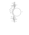
図7及び図8に示すように、プリント基板11は概ね矩形状であり、その背面側(図7(a)側)に横長矩形状の切欠き部11aが形成されている。その切欠き部11aには、伝熱機構19(伝熱部材)をなす金属製(例えばアルミニュウムなど)のバッテリホルダ19A(電池保持体)が取り付けられている。補助バッテリ14は円筒状であり、バッテリホルダ19Aは、その円筒の外周面の一部を長手方向に沿って保持するように、補助バッテリ14の円弧に合わせた曲面をなす保持部19Aaを有している。保持部19Aaに連続して、横長矩形状の取付け部19Abがあり、取付け部19Abは、プリント基板11の裏面に接触しており、取付け部19Abの両端が、ねじ30によりプリント基板11の表面側からねじ止めされている(図7(b),図8(b)参照)。
As shown in FIGS. 7 and 8, the printed
図7(b),図8(a)に示すように、取付け部19Abの位置に対応するプリント基板11の表面には、チップ抵抗からなる複数個のヒータ抵抗16が、切欠き部11aの長手方向に並ぶように配置されている。図9に示すように、バッテリホルダ19Aと補助バッテリ14及びプリント基板11との間には、伝熱機構19をなす伝熱シート19B(伝熱材)が介在している。伝熱シート19Bは、例えばシリコン系の弾性材であり、バッテリホルダ19A,補助バッテリ14及びプリント基板11に密着している。そして、補助バッテリ14は、図示されていない外装ケースの蓋が取り付けられる際に、その蓋の裏面により(正面図における)上方から押圧されて、バッテリホルダ19A上の伝熱シート19Bに圧着された状態で保持されている。
As shown in FIGS. 7B and 8A, on the surface of the printed
また、図9に示すように、プリント基板11の表面側に配置されているヒータ抵抗16と、その位置に対応する裏面、すなわち、バッテリホルダ19Aの取付け部19Abが伝熱シート19Bを介して接触している部分との間には、銅箔よりなるスルーホール23が形成されている。これにより、ヒータ抵抗16に通電が行われて発熱すると、その熱はスルーホール23を介してプリント基板11の裏面側に伝導され、更に伝熱シート19B,バッテリホルダ19A,補助バッテリ14へと伝導される。尚、図9では、スルーホール23を示す部分のみ断面で示している。
Further, as shown in FIG. 9, the
図7(b),図8(a)に示すように、ヒータ抵抗16の両側には、サーミスタ20,21がそれぞれ配置されている。これらのサーミスタ20,21は、何れもヒータ抵抗16の発熱を等しく検出するような位置関係となっており、プリント基板11の裏面側に配置されているバッテリホルダ19Aの取付け部19Abに近接するように配置されている。ただし、サーミスタ20は、制御回路3が補助バッテリ14の温度を検出するために設けられているので、サーミスタ20がこの位置で検出した温度に応じて、補助バッテリ14の実際の温度はどれ位になっているかの相関データを予め求めておき、制御回路3が温度検出を行うようにする。
その他、プリント基板11には、緊急通報通信回路4のモジュールや、緊急通報通信回路4にアンテナを接続するためのコネクタ24,制御回路3が車両側と通信を行うためのインターフェイスコネクタ25などが配置されている。
As shown in FIGS. 7B and 8A, the
In addition, the printed
次に、本実施形態の作用について図3から図5を参照して説明する。図3において、初期状態として、主電源スイッチ13は主バッテリ7側に接続されており、第1及び第2電源スイッチ17及び18は共にOFFになっている(S1)。制御回路3は。サーミスタ20により補助バッテリ14の温度を検出し(S2)、続いて、補助バッテリ14の電圧をチェック(1)する(S3)。
Next, the operation of the present embodiment will be described with reference to FIGS. In FIG. 3, as an initial state, the
次に、制御回路3は、第2電源スイッチ18のON/OFFをPWM信号により制御して、補助バッテリ14からの電源によりヒータ抵抗16に通電する電流が電流値Aとなるように制御する(S4)。その状態で補助バッテリ14の電圧をチェック(2)する(S5)。更に、制御回路3は、第2電源スイッチ18のON/OFFをPWM信号により制御して、ヒータ抵抗16に通電する電流が電流値B(>A)となるように制御し(S6)、その状態で補助バッテリ14の電圧をチェック(3)する(S7)。それから、第2電源スイッチ18をOFFする(S8)。
Next, the
次に、制御回路3は、ステップS3,S5,S7で検出した補助バッテリ14の各電圧の差が、ステップS2で検出した補助バッテリ14の温度に応じた閾値以内であるか否かを判断する(S9)。前記閾値以内であれば(YES)、補助バッテリ14は有効(機能は正常)であると判断し(S10)、ステップS11以降の処理を実行する。一方、前記閾値以内でなければ(NO)、補助バッテリ14は無効(故障又は寿命)であると判断し(S12)、補助バッテリ14が無効である旨を通知して(S13)処理を終了する。
Next, the
ここで、前記通知は、例えば車載用緊急通報装置1が警告用の表示器(LEDランプ等)を備えていれば、その表示器を点灯表示させる。また、例えば車載用緊急通報装置1が、車載LAN等を介して車両のボデーECU(Electronic Control Unit)等に接続されていれば、ボデーECUに対してメッセージ信号を送信し、車両のインストルメントパネルに表示を行わせても良い。
Here, for example, if the in-vehicle
また、ステップS9における補助バッテリ14の検出温度と各検出電圧の差との関係について、図4を参照して説明する。(a)に示す電流Aと(b)に示す電流Bとは(A<B)の関係にある。各電流値について設定した判定ラインは、補助バッテリ14の温度特性に基づいている。例えば、−10℃を下回るような低温領域では電圧降下量が急激に増大しており、電力を十分に供給できないおそれがある。
In addition, the relationship between the detected temperature of the
同じ温度であれば、出力電流値が大きい方が補助バッテリ14の電圧降下量も大きくなるので、図5に示すように、複数の電流値に基づき異なる判定ラインを設定するのが好ましい。例えば、低温時は出力電流が小さくても電圧降下量が大きいため判定精度に問題はないが、常温時や高温時は出力電流がある程度大きくならないと電圧降下量が大きくならない。したがって、後者のケースでは、出力電流が大きい時の電圧降下量により判定を行うことで判定精度を維持する。但し、1つの電流値について判定ラインを設定してもよいことは勿論である。
Since the voltage drop amount of the
また、ステップS9において、補助バッテリ14の異常判定を行うために電圧変化量を参照する際には、必ずしも第2電源スイッチ18のON/OFFをPWM信号により制御する必要はない。例えば、第2電源スイッチをOFFしている場合の補助バッテリ14の電圧から、第2電源スイッチを(連続的に)ONした場合の補助バッテリ14の電圧の降下量に基づいて異常判定を行っても良い。
Further, in step S9, when referring to the voltage change amount for determining the abnormality of the
一方、補助バッテリ14が有効であれば、ステップS9で求めた電圧差から、補助バッテリ14について動作可能温度の下限を推定する(S11)。それから、補助バッテリ14の温度と、サーミスタ21よりヒータ抵抗16の温度とを検出し(S14)、続くステップS15で、補助バッテリ14の予熱が必要か否かを判断する。ここでの判断条件は、
(補助バッテリ14の温度)≦(動作可能温度),且つ
(ヒータ抵抗16の温度)≦(過熱保護温度)
である。この条件が成立すると、補助バッテリ14の予熱が必要と判断する(YES)。
すると、ステップS16に移行して、ステップS11で推定した動作可能温度から、補助バッテリ14の昇温終止温度を決定する。それから、主バッテリ7の電圧をチェックして正常か否かを判断し(S17)、正常であれば(YES)ステップS18〜S25,異常であれば(NO)ステップS26〜S34を実行する。
On the other hand, if the
(Temperature of auxiliary battery 14) ≦ (Operating temperature) and (Temperature of heater resistor 16) ≦ (Overheat protection temperature)
It is. If this condition is satisfied, it is determined that the
Then, the process proceeds to step S16, and the temperature rise end temperature of the
ここで、ステップS11における電圧差と動作可能温度の下限との関係、及びステップS16における昇温終止温度との関係について説明する。例えば図6に示すように、ある測定時の電圧降下量が、図中にドットで示す補助バッテリ14の有効領域にあったとする。しかしながら、上記の電圧降下量は、図中に破線で示すシステムの動作限界を超えているため、このままで補助バッテリ14を使用することはできない(ここでは、上記「動作限界」は温度によらず一定と仮定している。また、厳密には、補助バッテリ14の電圧に応じて「動作限界」に対応する電圧降下量は変化する)。
Here, the relationship between the voltage difference in step S11 and the lower limit of the operable temperature and the relationship between the temperature rise end temperature in step S16 will be described. For example, as shown in FIG. 6, it is assumed that the amount of voltage drop during a certain measurement is in the effective area of the
そこで、図6中に(より細かい)破線で示すように、補助バッテリ14の温度特性を加味して、電圧降下量対温度の特性カーブを推定する。すると、前記特性カーブとシステム動作限界線との交点が「動作可能温度の下限」に対応する。その下限にマージンを加えた温度がステップS16における「昇温終止温度」になる(図6中の白抜きドット)。実際の処理としては、電圧降下量と電流値A,Bとに基づいて補助バッテリ14の内部抵抗値を算出し、内部抵抗の温度特性に基づいて有効/無効判定を行ったり、推定電圧降下量や動作可能温度の下限の算出などを行う。
Therefore, as shown by a (finer) broken line in FIG. 6, the voltage drop amount vs. temperature characteristic curve is estimated in consideration of the temperature characteristic of the
ステップS18では、システム(車載用緊急通報装置1)の動作状態をチェックし、ヒータ抵抗16への供給可能電流を算出する。供給可能電流が0Aを超えていれば(S19:YES)、第1電源スイッチ17を介してヒータ抵抗16に通電を行う。ここでも、第1電源スイッチ17をPWM信号によりON/OFFさせて、上記供給可能電流を超えない範囲となるように制御する(S20)。
In step S18, the operating state of the system (the vehicle-mounted emergency call device 1) is checked, and the current that can be supplied to the
次に、主バッテリ7の電圧をチェックし(S21)、主バッテリ7の電流供給能力があるか否かを判断する(S22)。電流供給能力があれば(YES)、補助バッテリ14の温度とヒータ抵抗16の温度とを検出し(S23)、以下の条件判断を行う(S24)。
(補助バッテリ14の温度)≦(昇温終止温度),且つ
(ヒータ抵抗16の温度)≦(過熱保護温度)
ここで「YES」と判断するとステップS18に戻り、上記の処理を繰り返す。そして、ステップS19,S22,S24の何れかで「NO」と判断すると、第1電源スイッチ17をOFFしてヒータ抵抗16への通電を停止する(S25)。それから、必要に応じてステップS14に戻る。
Next, the voltage of the
(Temperature of auxiliary battery 14) ≦ (temperature rise end temperature) and (temperature of heater resistor 16) ≦ (overheat protection temperature)
If "YES" is determined here, the process returns to step S18 to repeat the above processing. If “NO” is determined in any of steps S19, S22, and S24, the
一方、ステップS17で「NO」と判断すると、主電源スイッチ13を補助バッテリ14側に切り換える(S26)。尚、この処理は、ハードウェアで制御しても良い。次に、ステップS18,S19と同じ処理,判断を行い(S27,S28)、供給可能電流が0Aを超えていれば(S28:YES)、第2電源スイッチ18を介してヒータ抵抗16に通電を行う。すなわち、第2電源スイッチ18をPWM信号によりON/OFFさせて、上記供給可能電流を超えない範囲となるように制御する(S29)。
On the other hand, if "NO" is determined in the step S17, the
次に、補助バッテリ14の電圧をチェックし(S30)、補助バッテリ14の電流供給能力があるか否かを判断する(S31)。電流供給能力があれば(YES)、ステップS23,S24と同じ処理,判断を行う(S32,S33)。ステップS33で「YES」と判断するとステップS27に戻り、上記の処理を繰り返す。そして、ステップS28,S31,S33の何れかで「NO」と判断すると、第2電源スイッチ18をOFFしてヒータ抵抗16への通電を停止する(S34)。それから、必要に応じてステップS14に戻る。
Next, the voltage of the
また、ステップS15で「NO」と判断すると(補助バッテリ14の予熱が不要の場合)、ステップS14と同様に主バッテリ7の状態を監視し(S35)、正常であれば(YES)第1,第2電源スイッチ17,18はOFFのままにする(S36)。一方、異常であれば(NO)、ステップS26と同じ処理を行い(S37)ステップS36に移行する。
If it is determined “NO” in step S15 (when the
以上のように本実施形態によれば、主バッテリ7の予備電源として車載用緊急通報装置1に内蔵されている補助バッテリ14と、この補助バッテリ14を加熱するためのヒータ抵抗16とをプリント基板11に搭載する際に、ヒータ抵抗16が発した熱を補助バッテリ14電池に伝達する伝熱機構19を備える。そして、補助バッテリ14を、伝熱機構19を介してプリント基板11上に着脱可能に固定する。したがって、ヒータ抵抗16が発した熱を、伝熱機構19を介して補助バッテリ14に伝導させて補助バッテリ14を加熱できると共に、必要に応じて補助バッテリ14を伝熱機構19より着脱して容易に交換することができる。
As described above, according to the present embodiment, the
そして、ヒータ抵抗16を複数のチップ抵抗で構成してプリント基板11の表面側に配置し、伝熱機構19をプリント基板11の他方の裏面側に配置する。そして、プリント基板11におけるヒータ抵抗16が配置されている部分と伝熱部材が配置されている部分とに対応する位置にスルーホール23を形成し、そのスルーホール23を介してヒータ抵抗16から伝熱機構19への熱伝導を行う。
The
したがって、ヒータ抵抗16と伝熱機構19とをプリント基板11の両面にコンパクトに配置できると共に、両者間の熱伝導をスルーホール23を介して行うことで、熱の伝達効率も良好に維持できる。また、チップ抵抗のサイズや配置数を調整することで、補助バッテリ14の加熱態様を簡単且つ安価に調整できる。この場合、ヒータ抵抗16を、円筒状の外形を有する補助バッテリ14の長手方向に沿うように配置するので、補助バッテリ14を効率的に加熱することができる。
Therefore, the
また、伝熱機構19を、一端側の取付け部19Abがプリント基板11に固定され、他端側に保持部19Aaを有する形状の金属製のバッテリホルダ19Aと、プリント基板11とバッテリホルダ19A及び補助バッテリ14の間に介挿される伝熱シート19Bとを備えて構成した。これにより、伝熱シート19Bを介して、スルーホール23とバッテリホルダ19Aとを電気的に絶縁しつつ、プリント基板11とバッテリホルダ19Aとを熱的に結合できると共に、バッテリホルダ19Aと補助バッテリ14とも熱的に結合できる。したがって、ヒータ抵抗16が発生した熱を、プリント基板11→伝熱シート19B及びバッテリホルダ19A→補助バッテリ14の経路で、高い効率で伝導させることができる。また、伝熱シート19Bを押圧して使用することで伝熱面を密着させ、熱伝達効率を良好に維持すると同時に車両の振動による補助バッテリ14のがたつきを吸収し、がたつき音の発生を抑止することができる。
Further, the
更に、補助バッテリ14の温度を検出するためのサーミスタ20を、プリント基板11上において伝熱機構19に近接させて配置したので、補助バッテリ14の温度を、より高い精度で検出できる。
Further, since the
(第2実施形態)
以下、第1実施形態と同一部分には同一符号を付して説明を省略し、異なる部分について説明する。図10に示すように、第2実施形態は、第1実施形態のバッテリホルダ19A及び伝熱シート19Bに替えて、バッテリホルダ31(電池保持体,伝熱部材)を用いている。バッテリホルダ31は、弾性を有する部材(例えば伝熱ゴム,ABS等の樹脂,エラストマなど)で構成されており、保持部19Aa,取付け部19Abに対応する形状の保持部31a,取付け部31bを備えている。取付け部31bは、ねじ30によりプリント基板11に直接ねじ止めされており、補助バッテリ14は、保持部31aに直接接している。そして、補助バッテリ14は、外装ケースの蓋が取り付けられた際に蓋の裏面により(正面図における)上方から押圧されて、保持部31aに圧着された状態で保持される。
(Second Embodiment)
Hereinafter, the same parts as those in the first embodiment are denoted by the same reference numerals, description thereof will be omitted, and different parts will be described. As shown in FIG. 10, the second embodiment uses a battery holder 31 (battery holder, heat transfer member) instead of the
以上のように第2実施形態によれば、バッテリホルダ31を、弾性を有する部材で構成し、伝熱部材を単体としたので、より少ない部品で構成でき、プリント基板11への取り付け作業も簡単に行うことができる。
As described above, according to the second embodiment, since the
(第3実施形態)
図11に示す第3実施形態では、ヒータ抵抗16を、プリント基板32の裏面側に配置しており、ヒータ抵抗16と、バッテリホルダ19Aの取付け部19Abとが配置されている裏面には、銅箔(パターン)33が配置されている(スルーホール23は形成されていない)。したがって、ヒータ抵抗16が発した熱は、銅箔33→取付け部19Ab→保持部19Aaを経由して補助バッテリ14に伝導される。以上のように構成される第3実施形態による場合も、第1実施形態と同様の効果が得られる。
(Third embodiment)
In the third embodiment shown in FIG. 11, the
(第4実施形態)
図12に示すように、第4実施形態では、プリント基板41(回路基板)の形状が第1実施形態とは相違している。すなわち、切欠き部11aに替えて、矩形状の開口部41aが形成されている。そして、伝熱機構42をなすバッテリホルダ42A(伝熱部材,電池保持体)の形状は、図13に示すように、補助バッテリ14の外形に沿った曲面を有する保持部42Aaの前端部と後端部(図13では下端部と上端部)とに、それぞれ前側取り付け部42Afと後側取り付け部42Arとを備えている。
(Fourth embodiment)
As shown in FIG. 12, in the fourth embodiment, the shape of a printed circuit board 41 (circuit board) is different from that in the first embodiment. That is, a
また、伝熱シート42B(伝熱部材)は、バッテリホルダ42Aとプリント基板41及び補助バッテリ14との間に介挿されており、バッテリホルダ42Aは、前側取り付け部42Afと後側取り付け部42Arとが、それぞれねじ30によりねじ止めされている。そして、図12に示すように、前側取り付け部42Afと後側取り付け部42Arとが位置するプリント基板11の表面側には、開口部41aの長手方向に沿ってヒータ抵抗16が配置されている。また、それらに対応するプリント基板41の部位には、第1実施形態と同様にスルーホール44f,44rが形成されており。ヒータ抵抗16が発した熱は、スルーホール44f,44rを介して裏面側の前側取り付け部42Af,後側取り付け部42Arに伝達される。
Further, the
以上のように第4実施形態によれば、バッテリホルダ42Aを、その両端側がプリント基板41に固定され、両端の間に保持部42Aaを有する形状に構成し、ヒータ抵抗16を、プリント基板41の表面において補助バッテリ14の長手方向に沿うようにしてその両側に配置した。したがって、補助バッテリ14をより効率的に加熱することができる。
As described above, according to the fourth embodiment, the
尚、図12には、破線によりもう1つのサーミスタ21を示している。これは、例えばヒータ抵抗16が、補助バッテリ14の前方側に配置されている群(例えば16F)と後方側に配置されている群(例えば16R)とで独立して通電可能に構成され、それぞれの消費電力(発熱量)が異なるように設定されているとする。この場合、過熱保護回路22がハード的に過熱保護動作を行うために、各群の温度を独立して検出する必要があれば、破線で示すようにもう1つのサーミスタ21を配置する。
In FIG. 12, another
(第5実施形態)
第5実施形態は、第4実施形態の構成に第3実施形態の構成を適用したもので、プリント基板45の外形は、プリント基板41と同様である。図15に示すように、ヒータ抵抗16は、プリント基板45の裏面側に配置されており、スルーホール44f,44rに替えて、ヒータ抵抗16と、バッテリホルダ42Aの取付け部42Af,42Arとが配置されている裏面には、銅箔46f,46rが配置されている。したがって、ヒータ抵抗16が発した熱は、銅箔46f,46r→取付け部42Af,42Ar→保持部42Aaを経由して補助バッテリ14に伝導される。以上のように構成される第5実施形態による場合も、第3,第4実施形態と同様の効果が得られる。
(Fifth embodiment)
In the fifth embodiment, the configuration of the third embodiment is applied to the configuration of the fourth embodiment, and the outer shape of the printed
本発明は上記した、又は図面に記載した実施形態にのみ限定されるものではなく、以下のような変形又は拡張が可能である。
第1実施形態において、制御回路3は、補助バッテリ14の温度が動作可能温度以下に低下した際に、主バッテリ7側の電源供給能力を必ずしも確認する必要はなく、直ちに補助バッテリ14からヒータ抵抗16に通電しても良い。
The present invention is not limited to the embodiments described above or shown in the drawings, and the following modifications or expansions are possible.
In the first embodiment, the
発熱体は、ヒータ抵抗16のようなチップ抵抗以外のものを用いても良い。
伝熱シート19B,42Bは、プリント基板11,32,41,45に接触させる部分と補助バッテリ14に接触させる部分とが別体となる構造でも良く、また、弾性や厚みなどが異なる材質であっても良い。
A heating element other than a chip resistor such as the
The
サーミスタ21及び過熱保護回路22は、必要に応じて設ければ良い。
バッテリホルダの保持部を筒状として、その内部に補助バッテリを挿入しても良い。
第3実施形態において、ヒータ抵抗16を3つ以上備えても良い。
第4,第5実施形態において、伝熱機構42を、第2実施形態のように弾性を有する部材からなるバッテリホルダのみで構成しても良い。
車載用緊急通報装置以外に適用しても良い。
The
The battery holder holding portion may be cylindrical and an auxiliary battery may be inserted therein.
In the third embodiment, three or
In the fourth and fifth embodiments, the
You may apply other than the vehicle-mounted emergency call apparatus.
図面中、11はプリント基板(回路基板)、14は補助バッテリ(電池)、16はヒータ抵抗(発熱体)、19は伝熱機構(伝熱部材)、19Aバッテリホルダ(電池保持体)、19Bは伝熱シート(伝熱材)、20はサーミスタ(温度検出手段)、23はスルーホールを示す。 In the drawing, 11 is a printed circuit board (circuit board), 14 is an auxiliary battery (battery), 16 is a heater resistor (heat generating element), 19 is a heat transfer mechanism (heat transfer member), 19A battery holder (battery holder), 19B. Is a heat transfer sheet (heat transfer material), 20 is a thermistor (temperature detection means), and 23 is a through hole.
Claims (9)
この回路基板上に、着脱可能に固定される電池(14)と、
前記回路基板上に配置され、電源より通電が行われると発熱する発熱体(16)と、
この発熱体に接するように配置され、当該発熱体が発した熱を、前記電池に伝達する伝熱部材(19,31,42)とを備え、
前記電池は、前記伝熱部材を介して、前記回路基板上に着脱可能に固定され、
前記伝熱部材(19,42)は、
前記回路基板に固定されると共に、前記電池を保持する形状の電池保持部(19Aa,42Aa)を有して構成される金属製の電池保持体(19A,42A)と、
前記回路基板と前記電池保持体及び前記電池との間に介挿され、弾性を有するシート状の伝熱材(19B,42B)とを有し、
前記電池保持体(19A,31)は、一端側が前記回路基板に固定され、他端側に前記電池保持部を有する形状に構成され、
前記電池は、前記電池保持部へと押圧された状態で保持されることを特徴とする回路基板構造。 A circuit board (11, 32, 41, 45);
A battery (14) detachably fixed on the circuit board;
A heating element (16) disposed on the circuit board and generating heat when energized from a power source;
A heat transfer member (19, 31, 42) that is disposed in contact with the heating element and transmits heat generated by the heating element to the battery;
The battery is detachably fixed on the circuit board via the heat transfer member,
The heat transfer member (19, 42)
A battery holder (19A, 42A) made of metal that is fixed to the circuit board and has a battery holder (19Aa, 42Aa) shaped to hold the battery;
A sheet-like heat transfer material (19B, 42B) interposed between the circuit board, the battery holder and the battery, and having elasticity;
The battery holder (19A, 31) is configured to have a shape in which one end side is fixed to the circuit board and the other end side has the battery holding portion .
The battery, the circuit board structure according to claim Rukoto is held in the pressed into the battery holder.
この回路基板上に、着脱可能に固定される電池(14)と、
前記回路基板上に配置され、電源より通電が行われると発熱する発熱体(16)と、
この発熱体に接するように配置され、当該発熱体が発した熱を、前記電池に伝達する伝熱部材(19,31,42)とを備え、
前記電池は、前記伝熱部材を介して、前記回路基板上に着脱可能に固定され、
前記伝熱部材(19,42)は、
前記回路基板に固定されると共に、前記電池を保持する形状の電池保持部(19Aa,42Aa)を有して構成される金属製の電池保持体(19A,42A)と、
前記回路基板と前記電池保持体及び前記電池との間に介挿され、弾性を有するシート状の伝熱材(19B,42B)とを有し、
前記電池保持体(42A)は、両端側が前記回路基板に固定され、前記両端の間に前記電池保持部を有する形状に構成されていることを特徴とする回路基板構造。 A circuit board (11, 32, 41, 45);
A battery (14) detachably fixed on the circuit board;
A heating element (16) disposed on the circuit board and generating heat when energized from a power source;
A heat transfer member (19, 31, 42) that is disposed in contact with the heating element and transmits heat generated by the heating element to the battery;
The battery is detachably fixed on the circuit board via the heat transfer member,
The heat transfer member (19, 42)
A battery holder (19A, 42A) made of metal that is fixed to the circuit board and has a battery holder (19Aa, 42Aa) shaped to hold the battery;
A sheet-like heat transfer material (19B, 42B) interposed between the circuit board, the battery holder and the battery, and having elasticity;
The battery holder (42A) is configured to have a shape in which both ends are fixed to the circuit board and the battery holder is provided between the both ends .
この回路基板上に、着脱可能に固定される電池(14)と、
前記回路基板上に配置され、電源より通電が行われると発熱する発熱体(16)と、
この発熱体に接するように配置され、当該発熱体が発した熱を、前記電池に伝達する伝熱部材(19,31,42)とを備え、
前記電池は、前記伝熱部材を介して、前記回路基板上に着脱可能に固定され、
前記伝熱部材(31)は、
前記回路基板に固定されると共に、前記電池を保持する形状の電池保持部(31a)を有し、且つ弾性を有する部材からなる電池保持体で構成され、
前記電池保持体(19A,31)は、一端側が前記回路基板に固定され、他端側に前記電池保持部を有する形状に構成され、
前記電池は、前記電池保持部へと押圧された状態で保持されることを特徴とする回路基板構造。 A circuit board (11, 32, 41, 45);
A battery (14) detachably fixed on the circuit board;
A heating element (16) disposed on the circuit board and generating heat when energized from a power source;
A heat transfer member (19, 31, 42) that is disposed in contact with the heating element and transmits heat generated by the heating element to the battery;
The battery is detachably fixed on the circuit board via the heat transfer member,
The heat transfer member (31)
The battery holding body (31a) is shaped to hold the battery and is fixed to the circuit board, and is formed of a battery holder made of an elastic member.
The battery holder (19A, 31) is configured to have a shape in which one end side is fixed to the circuit board and the other end side has the battery holding portion .
The battery, the circuit board structure according to claim Rukoto is held in the pressed into the battery holder.
この回路基板上に、着脱可能に固定される電池(14)と、
前記回路基板上に配置され、電源より通電が行われると発熱する発熱体(16)と、
この発熱体に接するように配置され、当該発熱体が発した熱を、前記電池に伝達する伝熱部材(19,31,42)とを備え、
前記電池は、前記伝熱部材を介して、前記回路基板上に着脱可能に固定され、
前記伝熱部材(31)は、
前記回路基板に固定されると共に、前記電池を保持する形状の電池保持部(31a)を有し、且つ弾性を有する部材からなる電池保持体で構成され、
前記電池保持体(42A)は、両端側が前記回路基板に固定され、前記両端の間に前記電池保持部を有する形状に構成されていることを特徴とする回路基板構造。 A circuit board (11, 32, 41, 45);
A battery (14) detachably fixed on the circuit board;
A heating element (16) disposed on the circuit board and generating heat when energized from a power source;
A heat transfer member (19, 31, 42) that is disposed in contact with the heating element and transmits heat generated by the heating element to the battery;
The battery is detachably fixed on the circuit board via the heat transfer member,
The heat transfer member (31)
The battery holding body (31a) is shaped to hold the battery and is fixed to the circuit board, and is formed of a battery holder made of an elastic member.
The battery holder (42A) is configured to have a shape in which both ends are fixed to the circuit board and the battery holder is provided between the both ends .
前記伝熱部材は、前記回路基板の他方の面側に配置されており、
前記回路基板は、前記発熱体が配置されている部分と、前記伝熱部材が配置されている部分とに対応する位置にスルーホール(23,44)が形成されており、前記スルーホールを介して前記発熱体から前記伝熱部材への熱伝導が行われることを特徴とする請求項1から4の何れか一項に記載の回路基板構造。 The heating element is disposed on one surface side of the circuit board (11, 41),
The heat transfer member is disposed on the other surface side of the circuit board,
In the circuit board, through holes (23, 44) are formed at positions corresponding to a portion where the heating element is disposed and a portion where the heat transfer member is disposed, and the through hole is provided through the through hole. The circuit board structure according to any one of claims 1 to 4, wherein heat conduction from the heating element to the heat transfer member is performed.
前記発熱体は、前記電池の外形の長手方向に沿うように配置されていることを特徴とする請求項1から6の何れか一項に記載の回路基板構造。 The battery is cylindrical,
The circuit board structure according to any one of claims 1 to 6 , wherein the heating element is disposed along a longitudinal direction of the outer shape of the battery.
前記温度検出手段は、前記回路基板上において、前記伝熱部材に近接して配置されていることを特徴とする請求項1から8の何れか一項に記載の回路基板構造。 Temperature detection means (20) for detecting the temperature of the battery,
The circuit board structure according to any one of claims 1 to 8 , wherein the temperature detection unit is disposed on the circuit board in proximity to the heat transfer member.
Priority Applications (5)
| Application Number | Priority Date | Filing Date | Title |
|---|---|---|---|
| JP2014001626A JP6349731B2 (en) | 2014-01-08 | 2014-01-08 | Circuit board structure |
| DE112014006126.3T DE112014006126B4 (en) | 2014-01-08 | 2014-12-24 | circuit board arrangement |
| US15/109,937 US10211435B2 (en) | 2014-01-08 | 2014-12-24 | Circuit board structure |
| CN201480072571.4A CN105900278B (en) | 2014-01-08 | 2014-12-24 | Circuit substrate construction |
| PCT/JP2014/006412 WO2015104771A1 (en) | 2014-01-08 | 2014-12-24 | Circuit board structure |
Applications Claiming Priority (1)
| Application Number | Priority Date | Filing Date | Title |
|---|---|---|---|
| JP2014001626A JP6349731B2 (en) | 2014-01-08 | 2014-01-08 | Circuit board structure |
Publications (3)
| Publication Number | Publication Date |
|---|---|
| JP2015130288A JP2015130288A (en) | 2015-07-16 |
| JP2015130288A5 JP2015130288A5 (en) | 2016-02-18 |
| JP6349731B2 true JP6349731B2 (en) | 2018-07-04 |
Family
ID=53523628
Family Applications (1)
| Application Number | Title | Priority Date | Filing Date |
|---|---|---|---|
| JP2014001626A Active JP6349731B2 (en) | 2014-01-08 | 2014-01-08 | Circuit board structure |
Country Status (5)
| Country | Link |
|---|---|
| US (1) | US10211435B2 (en) |
| JP (1) | JP6349731B2 (en) |
| CN (1) | CN105900278B (en) |
| DE (1) | DE112014006126B4 (en) |
| WO (1) | WO2015104771A1 (en) |
Families Citing this family (10)
| Publication number | Priority date | Publication date | Assignee | Title |
|---|---|---|---|---|
| FR3042657B1 (en) * | 2015-10-16 | 2018-07-27 | Bubendorff | DEVICE FOR SUPPLYING OR CONTROLLING AN ELECTRIC MOTOR |
| CN106887562B (en) * | 2015-12-15 | 2020-12-04 | 小米科技有限责任公司 | Protection mainboard of battery cell, electronic terminal and assembly method of battery cell for electronic terminal |
| WO2018094418A1 (en) * | 2016-11-21 | 2018-05-24 | Sanmina Corporation | Using a heating element to manage energy storage cell equivalent series resistance (esr) |
| KR102307298B1 (en) * | 2017-08-30 | 2021-09-30 | 주식회사 엘지화학 | Battery Module for emergency telephone power supply |
| DE102018104935B4 (en) * | 2018-03-05 | 2023-02-09 | Dr. Ing. H.C. F. Porsche Aktiengesellschaft | Method, system and battery module for cooling power electronics contacted by spring action |
| JP2019192486A (en) * | 2018-04-25 | 2019-10-31 | 株式会社オートネットワーク技術研究所 | Power storage unit |
| CN108705943B (en) | 2018-05-22 | 2020-05-05 | 宁德时代新能源科技股份有限公司 | Battery pack heating device and control method |
| CN108711662B (en) * | 2018-05-22 | 2020-05-05 | 宁德时代新能源科技股份有限公司 | Battery pack heating device and control method |
| CN209071559U (en) * | 2018-11-15 | 2019-07-05 | 宁德时代新能源科技股份有限公司 | Battery monitoring unit and battery pack |
| CN116826213B (en) * | 2023-08-29 | 2023-11-17 | 深圳市岳松科技有限公司 | BMS protection board with battery control by temperature change monitoring |
Family Cites Families (14)
| Publication number | Priority date | Publication date | Assignee | Title |
|---|---|---|---|---|
| JPH09213459A (en) | 1996-02-02 | 1997-08-15 | Kojundo Chem Lab Co Ltd | Battery heating device |
| JP2002008604A (en) * | 2000-06-21 | 2002-01-11 | Sony Corp | Electronic device |
| TW501293B (en) * | 2001-01-06 | 2002-09-01 | Acer Inc | Method and device to raise the battery efficiency of portable electronic device |
| JP3749184B2 (en) * | 2002-01-31 | 2006-02-22 | 三洋電機株式会社 | Battery device for vehicle |
| JP4020650B2 (en) * | 2002-01-30 | 2007-12-12 | 三洋電機株式会社 | Battery device for vehicle |
| US20050074666A1 (en) | 2002-08-29 | 2005-04-07 | Hirokazu Kimiya | Heat control device for battery |
| JP2004111370A (en) * | 2002-08-29 | 2004-04-08 | Matsushita Electric Ind Co Ltd | Thermal control apparatus of battery |
| JP4390609B2 (en) | 2004-03-31 | 2009-12-24 | 三洋電機株式会社 | Power supply for vehicle |
| JP2007274373A (en) * | 2006-03-31 | 2007-10-18 | Casio Hitachi Mobile Communications Co Ltd | Electronic apparatus |
| JP2010054538A (en) * | 2008-08-26 | 2010-03-11 | Sea&Sea Sunpak Co Ltd | Heat radiator for battery stored in housing of stroboscope |
| JP2012204129A (en) * | 2011-03-25 | 2012-10-22 | Hitachi Maxell Ltd | Battery pack |
| JP5271462B1 (en) * | 2011-10-31 | 2013-08-21 | パナソニック株式会社 | Secondary battery unit |
| KR101431720B1 (en) * | 2011-12-13 | 2014-08-22 | 주식회사 엘지화학 | Switching Board of Novel Structure, and Battery Module Containing the Same |
| EP2736100B1 (en) * | 2012-11-22 | 2017-06-21 | Samsung SDI Co., Ltd. | Electronic unit with temperature measuring device for a battery system |
-
2014
- 2014-01-08 JP JP2014001626A patent/JP6349731B2/en active Active
- 2014-12-24 WO PCT/JP2014/006412 patent/WO2015104771A1/en active Application Filing
- 2014-12-24 CN CN201480072571.4A patent/CN105900278B/en active Active
- 2014-12-24 US US15/109,937 patent/US10211435B2/en active Active
- 2014-12-24 DE DE112014006126.3T patent/DE112014006126B4/en active Active
Also Published As
| Publication number | Publication date |
|---|---|
| CN105900278B (en) | 2019-07-23 |
| US20160336561A1 (en) | 2016-11-17 |
| CN105900278A (en) | 2016-08-24 |
| JP2015130288A (en) | 2015-07-16 |
| DE112014006126T5 (en) | 2016-10-27 |
| US10211435B2 (en) | 2019-02-19 |
| DE112014006126B4 (en) | 2022-09-29 |
| WO2015104771A1 (en) | 2015-07-16 |
Similar Documents
| Publication | Publication Date | Title |
|---|---|---|
| JP6349731B2 (en) | Circuit board structure | |
| JP6221749B2 (en) | Electronics | |
| WO2018083949A1 (en) | Vehicular battery monitoring device and vehicular battery monitoring system | |
| JP5208149B2 (en) | Protection circuit and battery pack | |
| CN111051140A (en) | Auxiliary power system | |
| JP7294793B2 (en) | heated hand grips for motorcycles | |
| WO2018066323A1 (en) | Vehicle battery monitoring device and vehicle battery monitoring system | |
| JP2008027826A (en) | Battery pack | |
| JP2008130007A (en) | On-vehicle emergency notification device | |
| WO2018163736A1 (en) | Protection circuit for in-vehicle battery | |
| JP2018049779A (en) | Controller for on-vehicle power storage unit and on-vehicle power storage apparatus | |
| JP2003509000A (en) | Semiconductor fuses for electrical loads | |
| JP5750399B2 (en) | Sensor belt device | |
| JP2007195021A (en) | Portable terminal device | |
| US20190256161A1 (en) | Independently heated handgrips for a motorcycle | |
| CN111886147B (en) | Heater device | |
| JP2009158219A (en) | On-vehicle power storage device | |
| WO2014184920A1 (en) | Battery monitoring apparatus, battery monitoring substrate, battery module, and battery system | |
| JP7382586B2 (en) | power system | |
| JP5607101B2 (en) | Sensor belt device | |
| EP4299387A1 (en) | Power system | |
| WO2018066220A1 (en) | Radiation heater device | |
| EP4299386A1 (en) | Power system | |
| JP2003072487A (en) | Onboard power source control device | |
| JP5085227B2 (en) | Resistor board type thermal fuse |
Legal Events
| Date | Code | Title | Description |
|---|---|---|---|
| A521 | Request for written amendment filed |
Free format text: JAPANESE INTERMEDIATE CODE: A523 Effective date: 20151225 |
|
| A621 | Written request for application examination |
Free format text: JAPANESE INTERMEDIATE CODE: A621 Effective date: 20160719 |
|
| A131 | Notification of reasons for refusal |
Free format text: JAPANESE INTERMEDIATE CODE: A131 Effective date: 20170905 |
|
| A521 | Request for written amendment filed |
Free format text: JAPANESE INTERMEDIATE CODE: A523 Effective date: 20171102 |
|
| TRDD | Decision of grant or rejection written | ||
| A01 | Written decision to grant a patent or to grant a registration (utility model) |
Free format text: JAPANESE INTERMEDIATE CODE: A01 Effective date: 20180508 |
|
| A61 | First payment of annual fees (during grant procedure) |
Free format text: JAPANESE INTERMEDIATE CODE: A61 Effective date: 20180521 |
|
| R151 | Written notification of patent or utility model registration |
Ref document number: 6349731 Country of ref document: JP Free format text: JAPANESE INTERMEDIATE CODE: R151 |
|
| S111 | Request for change of ownership or part of ownership |
Free format text: JAPANESE INTERMEDIATE CODE: R313113 |
|
| R350 | Written notification of registration of transfer |
Free format text: JAPANESE INTERMEDIATE CODE: R350 |
|
| R250 | Receipt of annual fees |
Free format text: JAPANESE INTERMEDIATE CODE: R250 |
|
| R250 | Receipt of annual fees |
Free format text: JAPANESE INTERMEDIATE CODE: R250 |
|
| R250 | Receipt of annual fees |
Free format text: JAPANESE INTERMEDIATE CODE: R250 |