EP3652399B1 - Dispositif de fermeture - Google Patents
Dispositif de fermeture Download PDFInfo
- Publication number
- EP3652399B1 EP3652399B1 EP18746584.4A EP18746584A EP3652399B1 EP 3652399 B1 EP3652399 B1 EP 3652399B1 EP 18746584 A EP18746584 A EP 18746584A EP 3652399 B1 EP3652399 B1 EP 3652399B1
- Authority
- EP
- European Patent Office
- Prior art keywords
- housing
- closure device
- plug
- connector
- slide
- Prior art date
- Legal status (The legal status is an assumption and is not a legal conclusion. Google has not performed a legal analysis and makes no representation as to the accuracy of the status listed.)
- Active
Links
- 230000005291 magnetic effect Effects 0.000 claims description 32
- 238000003780 insertion Methods 0.000 claims description 2
- 230000037431 insertion Effects 0.000 claims description 2
- 238000006073 displacement reaction Methods 0.000 description 9
- 230000000694 effects Effects 0.000 description 8
- 238000000034 method Methods 0.000 description 7
- 230000008569 process Effects 0.000 description 7
- 238000013459 approach Methods 0.000 description 4
- 230000005405 multipole Effects 0.000 description 2
- 230000007480 spreading Effects 0.000 description 2
- 230000008093 supporting effect Effects 0.000 description 2
- 208000012886 Vertigo Diseases 0.000 description 1
- 230000009471 action Effects 0.000 description 1
- 238000000418 atomic force spectrum Methods 0.000 description 1
- 230000008901 benefit Effects 0.000 description 1
- 230000015572 biosynthetic process Effects 0.000 description 1
- 230000008859 change Effects 0.000 description 1
- 238000010276 construction Methods 0.000 description 1
- 230000007423 decrease Effects 0.000 description 1
- 238000001514 detection method Methods 0.000 description 1
- 239000003302 ferromagnetic material Substances 0.000 description 1
- 238000005755 formation reaction Methods 0.000 description 1
- 230000005484 gravity Effects 0.000 description 1
- 238000001746 injection moulding Methods 0.000 description 1
- 239000002655 kraft paper Substances 0.000 description 1
- 230000002093 peripheral effect Effects 0.000 description 1
- 230000008092 positive effect Effects 0.000 description 1
- 230000002940 repellent Effects 0.000 description 1
- 239000005871 repellent Substances 0.000 description 1
Images


Classifications
-
- A—HUMAN NECESSITIES
- A44—HABERDASHERY; JEWELLERY
- A44B—BUTTONS, PINS, BUCKLES, SLIDE FASTENERS, OR THE LIKE
- A44B11/00—Buckles; Similar fasteners for interconnecting straps or the like, e.g. for safety belts
- A44B11/25—Buckles; Similar fasteners for interconnecting straps or the like, e.g. for safety belts with two or more separable parts
- A44B11/2503—Safety buckles
- A44B11/2507—Safety buckles actuated by a push-button
- A44B11/2515—Safety buckles actuated by a push-button acting parallel to the main plane of the buckle and perpendicularly to the direction of the fastening action
-
- A—HUMAN NECESSITIES
- A44—HABERDASHERY; JEWELLERY
- A44B—BUTTONS, PINS, BUCKLES, SLIDE FASTENERS, OR THE LIKE
- A44B11/00—Buckles; Similar fasteners for interconnecting straps or the like, e.g. for safety belts
- A44B11/25—Buckles; Similar fasteners for interconnecting straps or the like, e.g. for safety belts with two or more separable parts
- A44B11/258—Buckles; Similar fasteners for interconnecting straps or the like, e.g. for safety belts with two or more separable parts fastening by superposing one part on top of the other
-
- A—HUMAN NECESSITIES
- A44—HABERDASHERY; JEWELLERY
- A44B—BUTTONS, PINS, BUCKLES, SLIDE FASTENERS, OR THE LIKE
- A44B11/00—Buckles; Similar fasteners for interconnecting straps or the like, e.g. for safety belts
- A44B11/25—Buckles; Similar fasteners for interconnecting straps or the like, e.g. for safety belts with two or more separable parts
- A44B11/26—Buckles; Similar fasteners for interconnecting straps or the like, e.g. for safety belts with two or more separable parts with push-button fastenings
- A44B11/266—Buckles; Similar fasteners for interconnecting straps or the like, e.g. for safety belts with two or more separable parts with push-button fastenings with at least one push-button acting parallel to the main plane of the buckle and perpendicularly to the direction of the fastening action
-
- A—HUMAN NECESSITIES
- A45—HAND OR TRAVELLING ARTICLES
- A45C—PURSES; LUGGAGE; HAND CARRIED BAGS
- A45C13/00—Details; Accessories
- A45C13/10—Arrangement of fasteners
- A45C13/1069—Arrangement of fasteners magnetic
-
- A—HUMAN NECESSITIES
- A45—HAND OR TRAVELLING ARTICLES
- A45C—PURSES; LUGGAGE; HAND CARRIED BAGS
- A45C13/00—Details; Accessories
- A45C13/10—Arrangement of fasteners
- A45C13/1076—Arrangement of fasteners with a snap action
- A45C13/1092—Arrangement of fasteners with a snap action of the socket-and-pin type
-
- A—HUMAN NECESSITIES
- A45—HAND OR TRAVELLING ARTICLES
- A45C—PURSES; LUGGAGE; HAND CARRIED BAGS
- A45C13/00—Details; Accessories
- A45C13/10—Arrangement of fasteners
- A45C13/12—Arrangement of fasteners of press-button or turn-button fasteners
- A45C13/123—Arrangement of fasteners of press-button or turn-button fasteners of press-buttons
-
- A—HUMAN NECESSITIES
- A44—HABERDASHERY; JEWELLERY
- A44D—INDEXING SCHEME RELATING TO BUTTONS, PINS, BUCKLES OR SLIDE FASTENERS, AND TO JEWELLERY, BRACELETS OR OTHER PERSONAL ADORNMENTS
- A44D2203/00—Fastening by use of magnets
Definitions
- the invention relates to a locking device for connecting two parts according to the preamble of claim 1.
- Such a closure device has a plug and a housing with a plug receptacle into which the plug can be inserted in a closing direction to close the closure device.
- a slide is arranged on the housing in a slidable manner, which can be slid along an opening direction that differs from the closing direction in order to open the closure device.
- closure devices are used, for example, to connect two straps, as a closure for a bag, backpack, suitcase or box, as a closure device for other covers, such as a glove compartment, or as a closure for connecting any other parts.
- One part is to be connected to the connector and another part to the housing, so that the parts can be connected by arranging the connector in the connector receptacle of the housing.
- the plug In a closed position of the closure device, the plug is held mechanically on the housing.
- the slide can be displaced along the opening direction and the plug can thereby be detached from the housing, so that the plug is separated from the housing when the closure device is in an open position.
- At least one guide element is provided, which guides the plug into the closed position when it is inserted into the plug receptacle to close the closure device along the closing direction and supports the plug against tilting relative to the closing direction when the slide is moved to open the closure device.
- the fact that the opening direction differs from the closing direction is to be understood here to mean that the opening direction does not point along the closing direction, ie is also not directed in the opposite direction to the closing direction.
- the opening direction thus has an angle to the closing direction that differs from 0° and 180°.
- the closure device has a latching spring element which, when the closure device is in a closed position, holds the plug in a latching manner on the housing and can be moved out of engagement with the plug to open the closure device by moving the slide in the opening direction in order to release the plug from the housing, see above that in an open position of the closure device, the plug is separated from the housing. To open the closure device, the slide is thus moved in the opening direction and the detent spring element, which mechanically holds the plug in the closed position on the housing, is thereby moved.
- the slide therefore moves relative to the housing and to the plug, which causes the mechanical hold of the plug on the housing to be released.
- a force can also act on the plug, which is thus loaded relative to the housing and can tilt in the plug receptacle of the housing. This can make it difficult or even impossible to separate the plug from the housing and thus impair the operability of the locking device.
- A2 known closure device is a latching device for mechanically holding a plug on a housing provided, which is formed by a spring locking element on one of the plug and housing and a locking piece on the other of the plug and housing.
- the plug can be rotated relative to the housing, for example, in order to bring the latching device out of its latching engagement in this way, so that the plug can be removed from the housing.
- a magnet armature construction is provided, which causes a magnetic attraction force between the plug and the housing to support the closing process of the locking device.
- the DE 10 2011 086 960 A1 which discloses the preamble of claim 1 describes a closure device in which a plug is engageable with a spring locking element on a slider to close the closure device. By sliding the slider, the spring locking member can be moved relative to a housing to thereby disengage the spring locking member from the connector.
- a guide element for guiding the plug into the closed position and also for supporting the plug against tilting when opening is arranged on the housing.
- the WO 98/20765A1 describes a closure device in which the closure parts can be connected to one another in a latching manner and in which an electrical connection can also be established.
- the object of the present invention is to provide a closure device that can be closed and opened again in a simple, haptically pleasant manner.
- At least one first electrical contact element is arranged on the plug and at least one second electrical contact element is arranged on the housing, with the at least one first electrical contact element and the at least one second electrical contact element making electrical contact with one another in the closed position.
- a plurality of contact elements can be provided on the plug on the one hand and the housing or the slide on the other hand, so that in the closed position of the closure device a plurality of electrical connections are closed in parallel, so that multi-pole currents can be transmitted between the plug and the assembly of the housing and the slide.
- a guide element is arranged on the plug or on the housing, which has a supporting effect between the plug and the housing and in particular prevents the plug from tilting in the plug receptacle of the housing when the locking device is opened.
- the guide element facilitates the insertion of the plug into the plug receptacle.
- the guide element supports the plug in the plug receptacle in such a way that the position of the
- plug is defined relative to the housing and in particular the plug cannot easily tilt relative to the housing, so that it is ensured that after the slide has been actuated to open the locking device, the plug can be removed from the plug receptacle in a simple, haptically pleasant manner and the plug and the housing can thus be separated.
- one or more guide elements can be arranged anywhere on the plug and/or the housing, as long as they ensure that the position of the plug relative to the housing is defined in the closed position and thus only an axial movement of the plug relative to the housing along the closing direction is possible.
- At least one guide element is arranged on the plug receptacle, with the plug receptacle advantageously being formed by a cylindrical recess, for example, on the housing.
- the at least one guide element can be formed by a surface section on the plug receptacle of the housing, which extends along the closing direction and is in surface contact with the plug in the closed position. The fact that the guide element extends axially along the closing direction enables the plug to be guided axially while at the same time being fixed in position in the closed position, so that the plug cannot tilt in the plug receptacle.
- the at least one guide element can be arranged on the housing in such a way that the guide element supports the plug when the plug is subjected to a load acting in the closing direction relative to the housing.
- the guide element is thus arranged on a side of the plug receptacle, which the plug approaches when a load is applied in the opening direction, so that when the plug is loaded in the opening direction, the guide element comes into contact with the plug and supports the plug, so that the plug does not get in of the connector receptacle can tilt.
- the plug can have a pin, for example, with which the plug can be inserted into the plug receptacle.
- a first locking portion is advantageously arranged in the closed position with a second Latching section on the housing or the slide engages in a latching manner, so that in the closed position the plug is held in a latching manner on the housing via the pin.
- the pin advantageously rests against the at least one guide element, so that the position of the pin on the housing in the closed position is predetermined by one or more guide elements.
- the one or more guide elements thus serve, on the one hand, to guide the pin into the closed position when the plug is attached to the housing and, on the other hand, to fix and support the position of the plug on the housing in the closed position.
- the first locking section is preferably arranged circumferentially around the closing direction on the pin, so that the plug can be attached to the housing in different rotational positions.
- the second latching section can be arranged, for example, on a latching spring element that is attached to the slide.
- the detent spring element is spring-elastic in a direction transverse to the closing direction such that it can be spread when closing the closure device in the direction transverse to the closing direction, so that the detent spring element can latchingly engage with the latching section of the pin.
- the plug is inserted with its pin into the plug receptacle, so that the first latching section of the pin runs onto the second latching section of the latching spring element and thereby elastically pushes the latching spring element aside until the pin engages in a latching manner with the latching spring element.
- the detent spring element can, for example, be formed in one piece on the slide. However, it is also conceivable to arrange the detent spring element as an additional component on the slide, with the connection of the detent spring element to the slide being such that the detent spring element can be pushed aside elastically transversely to the closing direction in order to establish the connection between the plug and the detent spring element.
- the detent spring element is used to create a form-fitting connection of the plug with the slide and above it with the housing in order to mechanically hold the plug on the housing in the closed position.
- the detent spring element is such that by moving the slide in the opening direction of the positive engagement between the detent spring element and the pin of the plug is canceled, for example by the first detent section of the pin of the plug and the second detent section of the detent spring element on the slide being pushed out of engagement by moving the slide in the opening direction.
- the detent spring element can be formed by a circumferentially open ring which, in the closed position, at least partially encompasses the pin of the plug circumferentially around the closing direction.
- the plug in particular the pin of the plug, is designed, for example, to be essentially rotationally symmetrical about the closing direction.
- the peg can be cylindrical in its basic shape, with the (first) latching section being formed on an end of the peg pointing towards the housing (relative to an intended attachment of the plug to the plug receptacle of the housing) and running around the peg.
- the effect of this is that the plug can be attached to the plug receptacle of the housing in any rotational orientation about the closing direction and can be held on the housing so that it can rotate in the closed position.
- the slide is moved in the opening direction relative to the housing. Provision can be made for the slide to be moved counter to the opening direction relative to the housing, for example mechanically (spring-elastic), pneumatically, due to the force of gravity or magnetically in the direction of a position in which the plug can be mechanically connected to the housing to close the closure device. is biased. In this way, after the slide has been actuated to open the locking device, the slide can be automatically returned to a position in which the plug can be brought back into engagement with the housing or a detent spring element on the slide.
- the at least one first contact element is arranged on the pin.
- the electrical contact is thus made via the pin, which can carry one or more contact elements.
- one or more first contact elements can also be formed on a body of the plug which, in the closed position, is in planar contact with a housing section.
- First contact elements on the body can thus make contact with second contact elements on the housing section.
- magnetic means can be arranged on the plug on the one hand and/or the slide on the other hand, which magnetically support the closing of the closure device.
- the magnetic means are designed to bring about a magnetic attraction force between the plug and the housing and/or the slide in such a way that the plug engages with the plug receptacle in a magnetically assisted manner, advantageously essentially automatically, when approaching the plug receptacle is pulled, so that the closing process can be carried out largely automatically and thus in a haptically pleasant manner for a user.
- At least one magnet can be arranged, for example, on the plug and on the slide.
- the magnets on the plug and the slide can be configured in such a way that when the closure device is closed they have a magnetically attractive effect between the plug and the slide and thereby support the closing of the closure device magnetically.
- the magnetically opposite poles of the magnets of the plug and slide are moved away from one another and like poles of magnets on the plug and slide are brought closer together, so that a magnetic repulsive force is brought about between the plug and the slide, which acts in the opposite direction to the closing direction, and magnetically supports ejection of the plug from the plug receptacle on the housing.
- the magnet arrangement on the plug and on the slide can be designed in such a way that the magnetic repulsion force is at its maximum when the engagement between the plug and the housing (for example between the pin with its latching section on the plug and the latching spring element on the slide) is released and the plug can thus be removed.
- a magnetic repulsion when the closure device is opened can be achieved in that magnetically like poles are brought closer to one another when the slide is moved in the opening direction.
- magnetic repulsion also occurs, for example, when magnets that are magnetically attracted to each other with opposite poles in the closed position are moved tangentially with their opposite pole faces to each other when opening. If the magnets have at least approximately the same pole shape (i.e. the surfaces with which the poles face each other are essentially shaped the same) and the magnets are moved by a certain distance, e.g.
- the at least one second contact element can be arranged on the at least one guide element.
- the electrical contact can thus be made via one or more guide elements formed on the housing.
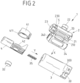
- closure device 1 which has a plug 2, a housing 3 and a slide 4 which is slidably arranged on the housing 3.
- the closure device 1 serves to connect two parts, for example as a closure for a bag, backpack or other flap, as a connection device for connecting two belts or ropes or for connecting two other parts.
- One part is attached to the plug 2, while the other part is connected to the housing 3.
- the connector 2 In a closed position, shown in Figure 3B , the connector 2 is held on the housing 3 so that the two parts are connected to one another via the connector 2 and the housing 3 .
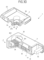
- an open position shown in Figure 3A and 3D , the connector 2 and the housing 3 are separate, so there is no connection between the parts.
- the plug 2 has a body 20 with a fastening device 23 for attaching a part (the fastening device 23 can, for example, be configured as a thread onto which a fastening part for clampingly attaching a component, for example a cover, a flap or the like, can be screwed can) and a pin 21 with a locking portion 210 on.
- the plug 2 can be plugged into a plug receptacle 30 on the housing 3 with the pin 21, so that in the closed position the plug 2 engages with the pin 21 in the plug receptacle 30 and with the latching section 210 of the pin 21 in a form-fitting manner with latching sections 410 of a spring locking element 41 on the slider 4 is engaged.
- the pin 21 of the plug 2 has a shape that is rotationally symmetrical about a closing direction X with a circumferential latching section 210 (see FIG 1 and 2 ).
- the plug 2 can be plugged into the circular plug socket 30 on the housing 3 with the pin 21 by the pin 21 being placed on the plug socket 30 in the closing direction X and brought into engagement with the latching sections 410 of the spring locking element 41 on the slide 4.
- the spring locking element 41 is arranged on a raised, protruding retaining element 42 of the slide 4 in such a way that the spring locking element 41 is fixed to the slide 4 along an opening direction Y, along which the slide is slidably mounted on the housing 3, transverse to the closing direction X and opening direction Y but elastically spread apart can be.
- the spring locking element 4 is essentially ring-shaped and has an opening 411 (see FIG 1 and 2 ) so that the spring locking element 41 can be spread open transversely to the closing direction X and opening direction Y in such a way that the plug 21 with the locking section 210 can run onto the locking sections 410 of the spring locking element 41 and thereby push the locking sections 410 radially outwards and thus the pin 21 snaps into engagement with the spring locking element 41 when the plug 2 is attached to the plug receptacle 30 in the closing direction X.
- the essentially ring-shaped spring locking element 41 is designed as a separate component and is arranged on the slide 4 . However, it is also conceivable to design the spring locking element 41 in one piece with the slide 4 .
- the slider 4 is arranged on the housing 3 so that it can be displaced along an opening direction Y and is guided on a sliding guide 31 of the housing 3 for this purpose.
- the slide 4 takes to close (see Figure 3A ) or in the closed position (see Figure 3B ) of the locking device 1 the in Figure 3A and 3B shown position, in which the detent spring element 41 is arranged concentrically to the connector receptacle 30 in such a way that the plug 2 with the pin 21 can be brought into engagement with the detent sections 410 of the detent spring element 41 or can stand.
- the pin 21 is positively engaged with the latching sections 410 of the latching spring element 41 via the circumferential latching section 210 so that the plug 2 cannot be removed from the housing 3 counter to the closing direction X.
- the slide 4 is guided along the opening direction Y on the housing 3, but is fixed relative to the housing 3 along the closing direction X, so that the engagement of the pin 21 with the latching spring element 41 means that the plug 2 can be locked via the slide 4 is held against the closing direction X on the housing 3.
- the slider 4 can be moved in an opening direction Y relative to the housing 3. Because the detent spring element 41 is held on the slide 4, the detent spring element 41 is moved together with the slide 4 in the opening direction Y, so that the pin 21 passes through the circumferential opening 411 (see FIG 1 and 2 ) of the detent spring element 41 occurs and thereby disengages from the detent sections 410 of the detent spring element 41 .
- the detent spring element 41 is not (no longer) in engagement with the pin 21 of the plug 2, so that the plug 2 is not (no longer) held on the housing 3 counter to the closing direction X and counter to the closing direction X from the plug receptacle 30 and thus from the housing 3 can be removed.
- a circuit results when using the closure device 1, which can be summarized as follows.
- the closure device 1 Before closing, the closure device 1 is in a position in which the plug 2 and the housing 3 are separated from one another and the slide 4 is in an initial position in which the detent spring element 41 is arranged concentrically with the plug receptacle 30 of the housing, see above that the pin 21 of the plug 2 can be brought into engagement with the detent spring element 41 in a detent manner.
- the plug 2 is now placed against the plug receptacle 30 in the closing direction X, so that the pin 21 with the circumferential latching section 210 runs onto the latching sections 410 of the latching spring element 41 and presses them apart in such a way that the latching spring 41 is transverse to the closing direction X and transverse is spread to the opening direction Y until the pin 21 snaps into engagement with the detent spring element 41 .
- the slide 4 When the plug 2 is placed on the housing 3, i.e. when the pin 21 engages with the detent spring element 41, the slide 4 is stationary in relation to the housing 3 and does not move in the opening direction Y. Only the detent spring element 41 is spread open in order in this way to establish a latching connection of the plug 2 with the housing 3.
- the slide 4 is pushed into the housing 3 in the opening direction Y, so that the detent spring element 41 disengages from the pin 21 by the pin 21 being moved through the peripheral opening 411 on the detent spring element 41 .
- the plug 2 can be removed from the housing 3 in the opposite direction to the closing direction X, so that in the open position, shown in 3D , the connector 2 and the housing 3 are separated from each other.
- the closure device 1 can be designed as a purely mechanical closure device 1 .
- the plug 2 must be pressed into the plug receptacle 30 in the closing direction X in order to close the closure device 1 in order to bring the pin 21 into locking engagement with the latching spring element 41 .
- the opening then also takes place purely mechanically by moving the slider 4 in the opening direction Y, with a restoring mechanical spring element 35 also being provided, which pushes the slider 4 in the direction of the in Figure 3A shown initial position and thus causes the slide 4 to return to the initial position after the closure device 1 has been opened, and the plug 2 can thus be brought back into engagement with the detent spring element 41 .
- the plug 2, the housing 3 and/or the slide 4 have magnetic means 22, 32, 34 which can be designed to support the closing and opening movement.
- the magnetic means 22, 32, 34 can be designed as magnets or as magnets on the one hand and as magnetic anchors made of a ferromagnetic material on the other hand, with each magnetic means 22, 32, 34 being able to consist of one or more elements.
- a magnet 22 is arranged on the plug 2, which in the closed position of the closure device 1 is a magnet or a magnetic anchor 32 in the region of the detent spring element 41 on the slide 4 opposite, with the magnet 22 on the plug 2 and the magnet or the magnetic armature 32 on the slide 4 causing a magnetic attraction force which magnetically supports the closing movement of the plug 2 in the closing direction X for the mechanical engagement of the pin 21 with the detent spring element 41.
- the magnetic forces of the magnet 22 on the one hand and the magnet or the magnetic armature 32 on the other hand can be dimensioned in such a way that the closing process takes place largely automatically when the connector 2 approaches the connector receptacle 30, in particular by the pin 21 with its latching section 210 being retracted largely automatically under Spreading of the detent spring element 41 is drawn into engagement with the detent sections 410 of the detent spring element 41 .
- a further magnet 34 is arranged, which, however, does not necessarily have to be provided and is to be regarded as optional insofar as this is the case.
- the provision of the additional magnet 34 has the advantage that the ejection of the plug 2 to open the closure device 1 can also be supported magnetically by the magnet 34 being brought closer to the magnet 22 on the pin 21 when the slide 4 is moved in the opening direction Y , wherein the magnets 34 and 22 with poles of the same name point towards one another and thus have a magnetically repellent effect.
- the magnet 34 In the open position of the slider 4, the magnet 34 is in the area of the connector receptacle 30 and thus below (seen in the closing direction X) the magnet 22 of the pin 21, so that a magnetic repulsion force acts on the connector 2 counter to the closing direction X, which attempts to eject the connector 2 from the connector receptacle 30.
- the opening process can thus be carried out easily and with a pleasant feel. Deliberate removal of the connector 2 from the connector receptacle 30 is not required.
- the displacement path of the slider 4 which leads to a release of the latching and thus to the opening of the closure device 1, can advantageously be dimensioned to a level in the range of this maximum, so that there is an advantageous ejection effect and, for Ejecting the connector 2 can be exploited.
- Two guide elements 301 , 302 are provided on the connector receptacle 30 , which extend axially in the direction of the closing direction X in the manner of webs from an upper side 300 of the housing 3 and are arranged on the border of the connector receptacle 30 .
- the one guide element 301 is on a front side of the connector receptacle 30 and the other guide element 302 on a rear side of the connector receptacle 30 - as seen in the opening direction Y.
- the guide elements 301, 302 serve, on the one hand, to guide the plug 2 with its pin 21 into engagement with the detent spring element 41 in the closing direction X when it is placed on the plug receptacle 30.
- the guide elements 301, 302 serve to support the pin 21 and thus the plug 2 when the slide 4 is moved to open the pre-connection device 1 relative to the housing 3, so that the plug 2 cannot tilt relative to the housing 3 and the pin 21 is held on the housing 3 in a coaxial position with respect to the closing direction X.
- the front guide element 301 which supports the pin 21 in particular when the slide 4 is displaced in the opening direction Y, is of particular importance here.
- the background here is that, in principle, the plug 2 and the pin 21 are not moved when the slide 4 is moved in the opening direction Y. Due to friction between the locking sections 210, 410 and due to magnetic forces acting between the magnetic means 22, 32, 34, however, there is a force on the plug 2, which may lead to the plug 2 tilting in the plug receptacle 30 and thereby possibly removing the plug 2 could affect.
- Preventing tilting can have a positive effect on the function in two respects: Firstly, the connector 2 can be prevented from getting caught in the housing 3 when it is opened. Secondly, an ejection effect can be achieved when using only two magnets 22, 32, which is stronger the more precisely the plug 2 is guided on the housing 3.
- the spring element 35 can in principle also be dispensed with as a restoring means for moving the slide 4 into the starting position after it has been actuated to open it. Because the magnetic means 22, 32, 34 also have a restoring effect in such a way that the slide 4 moves counter to the opening direction Y in the direction of the initial position when the pin 21 approaches the plug receptacle 30 of the housing 3 Figure 3A is pulled (the magnetic means 22, 32 on the pin or on the slide 4 attract each other, the magnetic means 22, 34 repel each other).
- resetting means can also be used, for example a pneumatic spring element, or resetting can take place due to the gravitational force acting on the slider 4 in a normal usage position (e.g. on a pocket).
- the closure device 1 can be used in particular to connect two belts.
- a fastening device 23, 33 can be arranged in the form of a belt fastening, which holds a belt in a clamping manner on the plug 2 or the housing 3.
- a clamping lever 24 can be provided (as, for example, in the exemplary embodiment on the plug 2), which must be released in order to hold a webbing in a clamped manner.
- the clamping lever 24 is pivoted about a pivot axis S on the body 20 via pivot pins 240, which engage in recesses 230 on the body 20 of the plug 2 when the clamping lever 24 is in the installed state, and is located on a side facing the housing 3 in the closed position of the body 20, so that in the closed position of the closure device 1 the clamping lever 24 is arranged between the plug 2 and the housing 3 and cannot be actuated to release the webbing from the plug 2.
- the exemplary embodiment of the closure device 1 shown in the illustration shows the plug 2 having a fixed pin 21 arranged on the body 20 .
- the pin 21 - as in the German patent application 10 2010 044 144.9 described - to be arranged on the body 20 so that it can be adjusted along the closing direction X, so that the pin 21 is retracted into the body 20, for example in a starting position, and is only extended out of the body 20 when it approaches the housing 3, for example under the action of the magnetic means 22, 32 is in order to be brought into engagement with the detent spring element 41 on the slider 4 can.
- the locking device 1 has a plug 2 with a single pin 21 and a housing 3 with a single plug receptacle 30 . It can be conceivable and advantageous to arrange a plurality of pins 21 on a plug 2 and correspondingly a plurality of plug receptacles 30 on a housing 3 . To open such a closure device 1, a slide can then be provided, which is designed in one piece and can be moved to release the connections of each pin 21 with an associated latching spring element 21 on the associated plug receptacle 30. Instead of a single slide, however, a plurality of slides can also be provided, which can either be operated individually or are coupled to one another for joint operation.
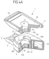
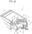
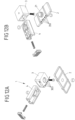
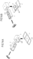
- FIG. 4A A further exemplary embodiment of a closure device 1 is shown Figures 4A to 4F in different positions of a plug 2, a housing 3 and a slide 4 in a position before closing ( Figure 4A ), while closing ( Figure 4B and 4C ), in a closed position ( Figure 4D ), When opening ( Figure 4E ) and in an open position with connector 2 and housing 3 disconnected ( Figure 4F ).
- the exemplary embodiment is essentially functionally the same as that described above with reference to FIG Figures 1 to 3 described embodiment, so that reference should be made to the above statements. Components with the same function are provided with the same reference symbols where appropriate.
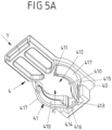
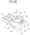
- Figure 5A and 5B show separate views of the slider 4 of the embodiment of FIG Figures 4A to 4F .
- a detent spring element 41 integrally formed on the slide 4 which can be produced, for example, as a plastic molded part by means of plastic injection molding.
- the detent spring element 41 is molded onto a body 40 of the slide 4 and is held on the body 40 via a holding section 414 .
- the detent spring element 41 has two lateral spring sections 417 which converge in a connecting section 416 and are cut free from the body 40 via cutouts 415 .
- the detent spring element 41 is formed onto the holding section 414 via the connecting section 416 and is held on the body 40 via this.
- the detent spring element 41 has a recess 413 into which the guide element 301 engages when it is closed and in the closed position (see FIG Figures 4A to 4D in synopsis with Fig. E.g Figure 3A , in which the guide element 301 is shown).
- the spring sections 417 of the detent spring element 41 follow a circular contour and form the detent spring element 41, which is essentially annular in shape and is open circumferentially through an opening 411, as above also for the exemplary embodiment according to FIG Figures 1 to 3 described.
- a receiving opening 412 is formed between the spring sections 417, in which the plug 2 with its pin 21 in the closed position (see Figure 4D ) is held in place.
- closure device 1 when closing ( Figures 4A to 4D ) and when opening ( Figure 4E and 4F ) is basically analogous to that described above Embodiment according to Figures 1 to 3 .
- the closure device 1 also has a circuit function, in which the plug 2 is inserted into the plug receptacle 30 of the housing 3 for closing in the closing direction X and is brought into engagement with the latching spring element 41 of the slide 4 in a latching manner, and for opening the slide 4 in the opening direction Y is shifted, the plug 2 is removed counter to the closing direction X and then the slider 4 is reset counter to the opening direction Y so that the closure device 1 can be closed again.
- the detent spring element 41 is not or at least only slightly resilient in the region of the connection of the spring sections 417 to the connecting section 416, the detent spring element 41 cannot yield elastically in the opening direction Y, so that the slide 4 as a whole moves slightly in the opening direction Y. until the latching section 210 snaps into engagement with the latching sections 410 and the closure device 1 moves into the closed position according to FIG Figure 4D reached.
- the movement of slide 4 in the opening direction Y is slight and comprises at most the width of the radial projection of the latching section 410 (i.e. the path that the latching spring element 41 has to avoid so that the latching sections 410 can engage with the latching section 210).
- the opening process is essentially analogous to that described above for the exemplary embodiment according to FIG Figures 1 to 3 described. It should be pointed out here that the closure device 1 does not open if the slide 4 is only moved in the opening direction Y by the distance that the slide 4 avoids when closing. To open, the slide 4 must be moved by a distance that is sufficient to disengage the pin 21 from the latching spring element 41 along the opening direction Y, as shown in FIG Figure 4E shown.
- a spigot 418 (see Figure 5B ) is provided on the slider 4 to define an end position of the slider 4 in the sliding guide 31 of the housing 3 when opening.
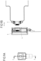
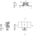
- FIG. 6A , 6B shown is in accordance with the embodiment 1 until 3A-3D a contact element 303 is arranged on the housing 3, which in the closed position ( Figure 6B ) with an associated contact element 211 of the plug 21 electrically contacted. In the closed position there is thus an electrical connection between the plug 2 and the housing 3 so that an electric current can be transmitted between the plug 2 and the housing 3 .
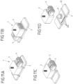
- two electrical contact elements 211 are arranged on a body 20 of the plug 2 in such a way that in the closed position of the closure device 1 ( Figures 7A, 7B ) point towards a housing section 304 of the housing 3 and are electrically contacted with contact elements 303 on the housing section 304 .
- the contact elements 211, 303 thus create two parallel, electrically separate connections between the plug 2 and the housing 3, so that different, multi-pole currents (+, -) can be transmitted between the plug 2 and the housing 3.
- any formations of contacts 200, 303 can in principle be arranged on the plug 2 and/or the housing 3.
- two rows of contacts 200 may be arranged.
- two rows of contacts 303 can be arranged on the housing 3 and/or contacts 200 arranged in a row along a square on the body 20 of the plug 2 .
- the number of contacts 200, 303 on the plug 2 on the one hand and on the housing 3 on the other hand can also be different, with the respective arrangement of the contacts 200, 303 along a row.
- the invention is not limited to the exemplary embodiments described above, but can also be implemented in completely different embodiments.
- the displacement path of the slider 4 does not necessarily have to be designed in a straight line, but can basically also have a different, curved shape. Accordingly, the opening direction Y can be curved.
- the displacement path can, for example, lie on a circular path around the closing direction X and thus in a plane perpendicular to the closing direction X.
- the displacement path on a circular path about a direction transverse to the closing direction X and transverse to the opening direction Y, so that the Shifting path lies in the plane spanned by the opening direction Y and the closing direction X.
- the slide can also be designed to be actuated by applying a tensile force (and not by applying a compressive force, as in the exemplary embodiments described above). This does not change the basic functioning of the locking device.
Claims (15)
- Dispositif de fermeture destiné à relier deux pièces, comprenant- un connecteur,- un boîtier qui comprend un logement de connecteur dans lequel le connecteur peut être inséré pour fermer le dispositif de fermeture dans une direction de fermeture,- un coulisseau disposé de manière coulissante sur le boîtier, qui peut être déplacé le long d'une direction d'ouverture différente de la direction de fermeture pour ouvrir le dispositif de fermeture, et- un élément de ressort d'encliquetage qui, dans une position de fermeture du dispositif de fermeture, maintient le connecteur par encliquetage sur le boîtier et qui, pour ouvrir le dispositif de fermeture, peut être déplacé hors de prise avec le connecteur en déplaçant le coulisseau dans la direction d'ouverture afin de détacher le connecteur du boîtier, de sorte que, dans une position d'ouverture du dispositif de fermeture, le connecteur est séparé du boîtier,- au moins un élément de guidage (301, 302) qui guide le connecteur (2) dans la position de fermeture le long de la direction de fermeture (X) lors de l'insertion dans le logement de connecteur (30) pour fermer le dispositif de fermeture (1), et qui soutient le connecteur (2) contre un basculement par rapport à la direction de fermeture (X) lors du déplacement du coulisseau (4) pour ouvrir le dispositif de fermeture (1),caractérisé en ce que
au moins un premier élément de contact électrique (200, 211) est disposé sur le connecteur (2) et au moins un deuxième élément de contact électrique (303) est disposé sur le boîtier (3) ou sur le coulisseau (4), l'au moins un premier élément de contact électrique (200, 211) et l'au moins un deuxième élément de contact électrique (303) étant en contact électrique l'un avec l'autre dans la position de fermeture. - Dispositif de fermeture selon la revendication 1, caractérisé en ce que l'au moins un élément de guidage (301, 302) est disposé sur le logement de connecteur (30).
- Dispositif de fermeture selon la revendication 1 ou 2, caractérisé en ce que le logement de connecteur (30) est formé par un évidement sur le boîtier (3).
- Dispositif de fermeture selon l'une quelconque des revendications 1 à 3, caractérisé en ce que l'au moins un élément de guidage (301, 302) est formé par un tronçon de surface sur le logement de connecteur (30) du boîtier (3), qui s'étend le long de la direction de fermeture (X) et qui est en contact à plat avec le connecteur (2) dans la position de fermeture.
- Dispositif de fermeture selon l'une quelconque des revendications précédentes, caractérisé en ce qu'au moins un élément de guidage (301) est disposé sur le boîtier (3) de telle sorte que l'élément de guidage (301) soutient le connecteur (2) par rapport au boîtier (3) en cas de charge du connecteur (2) agissant dans la direction d'ouverture (X).
- Dispositif de fermeture selon l'une quelconque des revendications précédentes, caractérisé en ce que le connecteur (2) présente un tenon (21) permettant d'insérer le connecteur (2) dans le logement de connecteur (30).
- Dispositif de fermeture selon la revendication 6, caractérisé en ce qu'un premier tronçon d'encliquetage (210) est disposé sur le tenon (21), qui, dans la position de fermeture, est en prise par encliquetage avec un deuxième tronçon d'encliquetage (410) sur le boîtier (3) ou le coulisseau (4).
- Dispositif de fermeture selon la revendication 6 ou 7, caractérisé en ce que l'élément de ressort d'encliquetage (41) est élastique dans une direction transversale à la direction de fermeture (X) de telle sorte que, lors de la fermeture du dispositif de fermeture (1), l'élément de ressort d'encliquetage (41) peut être écarté dans la direction transversale à la direction d'ouverture (Y).
- Dispositif de fermeture selon la revendication 8, caractérisé en ce qu'en déplaçant le coulisseau (4) dans la direction d'ouverture (Y), l'élément de ressort d'encliquetage (41) est dégagé du tenon (21) du connecteur (2).
- Dispositif de fermeture selon la revendication 8 ou 9, caractérisé en ce que, lorsque le coulisseau (4) est déplacé dans la direction d'ouverture (Y), l'élément de ressort d'encliquetage (41) est déplacé en même temps que le coulisseau (4).
- Dispositif de fermeture selon l'une quelconque des revendications 6 à 10, caractérisé en ce que l'au moins un premier élément de contact (200, 201) est disposé sur le tenon (21).
- Dispositif de fermeture selon l'une quelconque des revendications précédentes, caractérisé en ce que le coulisseau (4) est précontraint mécaniquement, pneumatiquement ou magnétiquement par rapport au boîtier (3) en direction d'une position dans laquelle le connecteur (2) peut être relié mécaniquement au boîtier (3) pour fermer le dispositif de fermeture (1).
- Dispositif de fermeture selon l'une quelconque des revendications précédentes, caractérisé en ce que des moyens magnétiques (22, 32) sont disposés sur le connecteur (2) d'une part et sur le boîtier (3) ou le coulisseau (4) d'autre part, qui assistent magnétiquement la fermeture du dispositif de fermeture (1).
- Dispositif de fermeture selon la revendication 13, caractérisé en ce qu'au moins un aimant (22, 32) est disposé sur le connecteur (2) et sur le coulisseau (4) respectivement.
- Dispositif de fermeture) selon l'une quelconque des revendications précédentes, caractérisé en ce que l'au moins un deuxième élément de contact (303) est disposé sur l'au moins un élément de guidage (301, 302) du boîtier (3).
Applications Claiming Priority (2)
| Application Number | Priority Date | Filing Date | Title |
|---|---|---|---|
| DE102017212152.1A DE102017212152A1 (de) | 2017-07-14 | 2017-07-14 | Verschlussvorrichtung |
| PCT/EP2018/068440 WO2019011821A1 (fr) | 2017-07-14 | 2018-07-06 | Dispositif de fermeture |
Publications (2)
| Publication Number | Publication Date |
|---|---|
| EP3652399A1 EP3652399A1 (fr) | 2020-05-20 |
| EP3652399B1 true EP3652399B1 (fr) | 2023-04-12 |
Family
ID=63041961
Family Applications (1)
| Application Number | Title | Priority Date | Filing Date |
|---|---|---|---|
| EP18746584.4A Active EP3652399B1 (fr) | 2017-07-14 | 2018-07-06 | Dispositif de fermeture |
Country Status (3)
| Country | Link |
|---|---|
| EP (1) | EP3652399B1 (fr) |
| DE (1) | DE102017212152A1 (fr) |
| WO (1) | WO2019011821A1 (fr) |
Families Citing this family (9)
| Publication number | Priority date | Publication date | Assignee | Title |
|---|---|---|---|---|
| DE102019201259A1 (de) * | 2019-01-31 | 2020-08-06 | Fidlock Gmbh | Verschlussvorrichtung mit aneinander ansetzbaren Verschlussteilen |
| CN109662399B (zh) * | 2019-02-27 | 2024-02-20 | 联扬塑胶(深圳)有限公司 | 磁性搭扣 |
| DE102019002700A1 (de) * | 2019-04-12 | 2020-10-15 | Dräger Safety AG & Co. KGaA | Gurtverschlusssystem und Atemluftversorgungsgerät für Gurtverschlusssystem |
| DE202019103812U1 (de) * | 2019-07-10 | 2020-10-14 | Sudhaus Gmbh | Schloss und Behälter mit einem solchen Schloss |
| DE102020207310B4 (de) * | 2020-06-11 | 2021-12-30 | Fidlock Gmbh | Bei Belastung gesicherte Verschlussvorrichtung |
| CN114027591B (zh) * | 2020-09-09 | 2024-02-20 | 联扬塑胶(深圳)有限公司 | 拨动解锁的扣具装置 |
| TWI746392B (zh) | 2021-03-17 | 2021-11-11 | 競泰股份有限公司 | 磁性扣合裝置 |
| CN114027582B (zh) * | 2021-04-18 | 2023-09-15 | 联扬塑胶(深圳)有限公司 | 磁性扣具 |
| DE102021206640A1 (de) * | 2021-06-25 | 2022-12-29 | Fidlock Gmbh | Magnetische Verschlussvorrichtung mit einem Hemmelement |
Family Cites Families (4)
| Publication number | Priority date | Publication date | Assignee | Title |
|---|---|---|---|---|
| US5806152A (en) * | 1996-11-15 | 1998-09-15 | Massachusetts Institute Of Technology | Compliant latching fastener |
| AU2007272165B2 (en) | 2006-07-12 | 2012-10-04 | Fidlock Gmbh | Mechanic-magnetic connecting structure |
| DE102010044144B3 (de) | 2010-11-18 | 2012-05-31 | Fidlock Gmbh | Verschlussvorrichtung |
| DE102011086960A1 (de) * | 2011-11-23 | 2013-05-23 | Fidlock Gmbh | Verschlussvorrichtung |
-
2017
- 2017-07-14 DE DE102017212152.1A patent/DE102017212152A1/de active Pending
-
2018
- 2018-07-06 WO PCT/EP2018/068440 patent/WO2019011821A1/fr unknown
- 2018-07-06 EP EP18746584.4A patent/EP3652399B1/fr active Active
Also Published As
| Publication number | Publication date |
|---|---|
| WO2019011821A1 (fr) | 2019-01-17 |
| DE102017212152A1 (de) | 2019-01-17 |
| EP3652399A1 (fr) | 2020-05-20 |
Similar Documents
| Publication | Publication Date | Title |
|---|---|---|
| EP3652399B1 (fr) | Dispositif de fermeture | |
| EP2782468B1 (fr) | Dispositif de fermeture | |
| DE102014101952B4 (de) | Steckverbinderteil mit einem Rastelement | |
| EP3235061B1 (fr) | Borne de connexion électrique | |
| EP3220781B1 (fr) | Dispositif de fermeture permettant de fixer un appareil électronique à un dispositif de retenue | |
| EP3167130B1 (fr) | Dispositif de fermeture à actionnement manuel avec système de temporisation | |
| EP2923418B1 (fr) | Mécanisme de verrouillage pour connecteur enfichable | |
| WO2011015340A1 (fr) | Dispositif enfichable sous forme d'une fiche d'allume-cigare, en particulier pour des véhicules automobiles | |
| DE202008017699U1 (de) | Elektromechanisches Verbindungssystem | |
| DE19920481C1 (de) | Selbstverriegelnde elektrische Steckverbindung, insbesondere für Kfz-Anwendungen | |
| DE102014011576B3 (de) | Brandmelder mit Verriegelung und Verfahren zum Ver- und Entriegeln von einem Melderteil mit einem Sockelteil eines Brandmelders | |
| EP4277489A1 (fr) | Dispositif de fermeture mécanique magnétique | |
| DE10216209C1 (de) | Berührungsschutzvorrichtung mit Längsschieber für eine elektrische Steckdose | |
| EP3651608B1 (fr) | Dispositif de verrouillage avec contacts électriques | |
| DE4336931C2 (de) | In eine elektrische Schutzkontaktsteckdose nachträglich einsetzbare Kinderschutzsicherung | |
| EP4049343A1 (fr) | Dispositif terminal servant à connecter un conducteur électrique | |
| EP3345261B1 (fr) | Porte-contact | |
| DE102022206462B3 (de) | Haltevorrichtung zum Halten eines Gegenstands an einer Baugruppe | |
| DE10313667B3 (de) | Stecker mit Schieber zum Verbinden mit einer Steckbuchse | |
| EP3652811B1 (fr) | Dispositif de fermeture | |
| DE2554177A1 (de) | Schaltelement | |
| DE1144810B (de) | Elektrische, von einer Geraetetuer betaetigte Schaltfassung | |
| DE1970597U (de) | Tastschalter zum einbau in kuehlmoebeln od. dgl. | |
| DE1497476C (de) | Fassung zur Aufnahme des Fußteüs einer mehrere Blitzlampen aufweisenden Blitzlampeneinheit | |
| DE1047921B (de) | Bimetallsicherungsautomat mit im wesentlichen parallel zum Schaltstift verlaufender, von einer Heizwicklung umgebener Bimetallfeder |
Legal Events
| Date | Code | Title | Description |
|---|---|---|---|
| STAA | Information on the status of an ep patent application or granted ep patent |
Free format text: STATUS: UNKNOWN |
|
| STAA | Information on the status of an ep patent application or granted ep patent |
Free format text: STATUS: THE INTERNATIONAL PUBLICATION HAS BEEN MADE |
|
| PUAI | Public reference made under article 153(3) epc to a published international application that has entered the european phase |
Free format text: ORIGINAL CODE: 0009012 |
|
| STAA | Information on the status of an ep patent application or granted ep patent |
Free format text: STATUS: REQUEST FOR EXAMINATION WAS MADE |
|
| 17P | Request for examination filed |
Effective date: 20200210 |
|
| AK | Designated contracting states |
Kind code of ref document: A1 Designated state(s): AL AT BE BG CH CY CZ DE DK EE ES FI FR GB GR HR HU IE IS IT LI LT LU LV MC MK MT NL NO PL PT RO RS SE SI SK SM TR |
|
| AX | Request for extension of the european patent |
Extension state: BA ME |
|
| DAV | Request for validation of the european patent (deleted) | ||
| DAX | Request for extension of the european patent (deleted) | ||
| RAP1 | Party data changed (applicant data changed or rights of an application transferred) |
Owner name: FIDLOCK GMBH |
|
| RIN1 | Information on inventor provided before grant (corrected) |
Inventor name: FIEDLER, JOACHIM Inventor name: BOTKUS, BREIDO |
|
| GRAP | Despatch of communication of intention to grant a patent |
Free format text: ORIGINAL CODE: EPIDOSNIGR1 |
|
| STAA | Information on the status of an ep patent application or granted ep patent |
Free format text: STATUS: GRANT OF PATENT IS INTENDED |
|
| INTG | Intention to grant announced |
Effective date: 20221025 |
|
| GRAS | Grant fee paid |
Free format text: ORIGINAL CODE: EPIDOSNIGR3 |
|
| GRAA | (expected) grant |
Free format text: ORIGINAL CODE: 0009210 |
|
| STAA | Information on the status of an ep patent application or granted ep patent |
Free format text: STATUS: THE PATENT HAS BEEN GRANTED |
|
| AK | Designated contracting states |
Kind code of ref document: B1 Designated state(s): AL AT BE BG CH CY CZ DE DK EE ES FI FR GB GR HR HU IE IS IT LI LT LU LV MC MK MT NL NO PL PT RO RS SE SI SK SM TR |
|
| REG | Reference to a national code |
Ref country code: GB Ref legal event code: FG4D Free format text: NOT ENGLISH |
|
| REG | Reference to a national code |
Ref country code: CH Ref legal event code: EP |
|
| REG | Reference to a national code |
Ref country code: DE Ref legal event code: R096 Ref document number: 502018011951 Country of ref document: DE |
|
| REG | Reference to a national code |
Ref country code: IE Ref legal event code: FG4D Free format text: LANGUAGE OF EP DOCUMENT: GERMAN |
|
| REG | Reference to a national code |
Ref country code: AT Ref legal event code: REF Ref document number: 1559871 Country of ref document: AT Kind code of ref document: T Effective date: 20230515 |
|
| P01 | Opt-out of the competence of the unified patent court (upc) registered |
Effective date: 20230517 |
|
| REG | Reference to a national code |
Ref country code: LT Ref legal event code: MG9D |
|
| REG | Reference to a national code |
Ref country code: NL Ref legal event code: MP Effective date: 20230412 |
|
| PG25 | Lapsed in a contracting state [announced via postgrant information from national office to epo] |
Ref country code: NL Free format text: LAPSE BECAUSE OF FAILURE TO SUBMIT A TRANSLATION OF THE DESCRIPTION OR TO PAY THE FEE WITHIN THE PRESCRIBED TIME-LIMIT Effective date: 20230412 |
|
| PG25 | Lapsed in a contracting state [announced via postgrant information from national office to epo] |
Ref country code: SE Free format text: LAPSE BECAUSE OF FAILURE TO SUBMIT A TRANSLATION OF THE DESCRIPTION OR TO PAY THE FEE WITHIN THE PRESCRIBED TIME-LIMIT Effective date: 20230412 Ref country code: PT Free format text: LAPSE BECAUSE OF FAILURE TO SUBMIT A TRANSLATION OF THE DESCRIPTION OR TO PAY THE FEE WITHIN THE PRESCRIBED TIME-LIMIT Effective date: 20230814 Ref country code: NO Free format text: LAPSE BECAUSE OF FAILURE TO SUBMIT A TRANSLATION OF THE DESCRIPTION OR TO PAY THE FEE WITHIN THE PRESCRIBED TIME-LIMIT Effective date: 20230712 Ref country code: ES Free format text: LAPSE BECAUSE OF FAILURE TO SUBMIT A TRANSLATION OF THE DESCRIPTION OR TO PAY THE FEE WITHIN THE PRESCRIBED TIME-LIMIT Effective date: 20230412 |
|
| PG25 | Lapsed in a contracting state [announced via postgrant information from national office to epo] |
Ref country code: RS Free format text: LAPSE BECAUSE OF FAILURE TO SUBMIT A TRANSLATION OF THE DESCRIPTION OR TO PAY THE FEE WITHIN THE PRESCRIBED TIME-LIMIT Effective date: 20230412 Ref country code: PL Free format text: LAPSE BECAUSE OF FAILURE TO SUBMIT A TRANSLATION OF THE DESCRIPTION OR TO PAY THE FEE WITHIN THE PRESCRIBED TIME-LIMIT Effective date: 20230412 Ref country code: LV Free format text: LAPSE BECAUSE OF FAILURE TO SUBMIT A TRANSLATION OF THE DESCRIPTION OR TO PAY THE FEE WITHIN THE PRESCRIBED TIME-LIMIT Effective date: 20230412 Ref country code: LT Free format text: LAPSE BECAUSE OF FAILURE TO SUBMIT A TRANSLATION OF THE DESCRIPTION OR TO PAY THE FEE WITHIN THE PRESCRIBED TIME-LIMIT Effective date: 20230412 Ref country code: IS Free format text: LAPSE BECAUSE OF FAILURE TO SUBMIT A TRANSLATION OF THE DESCRIPTION OR TO PAY THE FEE WITHIN THE PRESCRIBED TIME-LIMIT Effective date: 20230812 Ref country code: HR Free format text: LAPSE BECAUSE OF FAILURE TO SUBMIT A TRANSLATION OF THE DESCRIPTION OR TO PAY THE FEE WITHIN THE PRESCRIBED TIME-LIMIT Effective date: 20230412 Ref country code: GR Free format text: LAPSE BECAUSE OF FAILURE TO SUBMIT A TRANSLATION OF THE DESCRIPTION OR TO PAY THE FEE WITHIN THE PRESCRIBED TIME-LIMIT Effective date: 20230713 Ref country code: AL Free format text: LAPSE BECAUSE OF FAILURE TO SUBMIT A TRANSLATION OF THE DESCRIPTION OR TO PAY THE FEE WITHIN THE PRESCRIBED TIME-LIMIT Effective date: 20230412 |
|
| PGFP | Annual fee paid to national office [announced via postgrant information from national office to epo] |
Ref country code: DE Payment date: 20230720 Year of fee payment: 6 |
|
| PG25 | Lapsed in a contracting state [announced via postgrant information from national office to epo] |
Ref country code: FI Free format text: LAPSE BECAUSE OF FAILURE TO SUBMIT A TRANSLATION OF THE DESCRIPTION OR TO PAY THE FEE WITHIN THE PRESCRIBED TIME-LIMIT Effective date: 20230412 |
|
| REG | Reference to a national code |
Ref country code: DE Ref legal event code: R097 Ref document number: 502018011951 Country of ref document: DE |
|
| PG25 | Lapsed in a contracting state [announced via postgrant information from national office to epo] |
Ref country code: SK Free format text: LAPSE BECAUSE OF FAILURE TO SUBMIT A TRANSLATION OF THE DESCRIPTION OR TO PAY THE FEE WITHIN THE PRESCRIBED TIME-LIMIT Effective date: 20230412 |
|
| PG25 | Lapsed in a contracting state [announced via postgrant information from national office to epo] |
Ref country code: SM Free format text: LAPSE BECAUSE OF FAILURE TO SUBMIT A TRANSLATION OF THE DESCRIPTION OR TO PAY THE FEE WITHIN THE PRESCRIBED TIME-LIMIT Effective date: 20230412 Ref country code: SK Free format text: LAPSE BECAUSE OF FAILURE TO SUBMIT A TRANSLATION OF THE DESCRIPTION OR TO PAY THE FEE WITHIN THE PRESCRIBED TIME-LIMIT Effective date: 20230412 Ref country code: RO Free format text: LAPSE BECAUSE OF FAILURE TO SUBMIT A TRANSLATION OF THE DESCRIPTION OR TO PAY THE FEE WITHIN THE PRESCRIBED TIME-LIMIT Effective date: 20230412 Ref country code: EE Free format text: LAPSE BECAUSE OF FAILURE TO SUBMIT A TRANSLATION OF THE DESCRIPTION OR TO PAY THE FEE WITHIN THE PRESCRIBED TIME-LIMIT Effective date: 20230412 Ref country code: DK Free format text: LAPSE BECAUSE OF FAILURE TO SUBMIT A TRANSLATION OF THE DESCRIPTION OR TO PAY THE FEE WITHIN THE PRESCRIBED TIME-LIMIT Effective date: 20230412 Ref country code: CZ Free format text: LAPSE BECAUSE OF FAILURE TO SUBMIT A TRANSLATION OF THE DESCRIPTION OR TO PAY THE FEE WITHIN THE PRESCRIBED TIME-LIMIT Effective date: 20230412 |
|
| PLBE | No opposition filed within time limit |
Free format text: ORIGINAL CODE: 0009261 |
|
| STAA | Information on the status of an ep patent application or granted ep patent |
Free format text: STATUS: NO OPPOSITION FILED WITHIN TIME LIMIT |
|
| PG25 | Lapsed in a contracting state [announced via postgrant information from national office to epo] |
Ref country code: MC Free format text: LAPSE BECAUSE OF FAILURE TO SUBMIT A TRANSLATION OF THE DESCRIPTION OR TO PAY THE FEE WITHIN THE PRESCRIBED TIME-LIMIT Effective date: 20230412 |
|
| PG25 | Lapsed in a contracting state [announced via postgrant information from national office to epo] |
Ref country code: MC Free format text: LAPSE BECAUSE OF FAILURE TO SUBMIT A TRANSLATION OF THE DESCRIPTION OR TO PAY THE FEE WITHIN THE PRESCRIBED TIME-LIMIT Effective date: 20230412 |
|
| REG | Reference to a national code |
Ref country code: CH Ref legal event code: PL |
|
| REG | Reference to a national code |
Ref country code: BE Ref legal event code: MM Effective date: 20230731 |
|
| 26N | No opposition filed |
Effective date: 20240115 |
|
| PG25 | Lapsed in a contracting state [announced via postgrant information from national office to epo] |
Ref country code: LU Free format text: LAPSE BECAUSE OF NON-PAYMENT OF DUE FEES Effective date: 20230706 |
|
| GBPC | Gb: european patent ceased through non-payment of renewal fee |
Effective date: 20230712 |
|
| PG25 | Lapsed in a contracting state [announced via postgrant information from national office to epo] |
Ref country code: LU Free format text: LAPSE BECAUSE OF NON-PAYMENT OF DUE FEES Effective date: 20230706 |
|
| PG25 | Lapsed in a contracting state [announced via postgrant information from national office to epo] |
Ref country code: GB Free format text: LAPSE BECAUSE OF NON-PAYMENT OF DUE FEES Effective date: 20230712 Ref country code: CH Free format text: LAPSE BECAUSE OF NON-PAYMENT OF DUE FEES Effective date: 20230731 |
|
| PG25 | Lapsed in a contracting state [announced via postgrant information from national office to epo] |
Ref country code: SI Free format text: LAPSE BECAUSE OF FAILURE TO SUBMIT A TRANSLATION OF THE DESCRIPTION OR TO PAY THE FEE WITHIN THE PRESCRIBED TIME-LIMIT Effective date: 20230412 |