EP3650712A1 - Dispositif d'assemblage de deux supports superposés assurant une liaison entre les supports avec une aptitude de déplacement relatif et d'amortissement - Google Patents
Dispositif d'assemblage de deux supports superposés assurant une liaison entre les supports avec une aptitude de déplacement relatif et d'amortissement Download PDFInfo
- Publication number
- EP3650712A1 EP3650712A1 EP19206826.0A EP19206826A EP3650712A1 EP 3650712 A1 EP3650712 A1 EP 3650712A1 EP 19206826 A EP19206826 A EP 19206826A EP 3650712 A1 EP3650712 A1 EP 3650712A1
- Authority
- EP
- European Patent Office
- Prior art keywords
- support
- main axis
- spacer
- assembly device
- along
- Prior art date
- Legal status (The legal status is an assumption and is not a legal conclusion. Google has not performed a legal analysis and makes no representation as to the accuracy of the status listed.)
- Granted
Links
Images


Classifications
-
- B—PERFORMING OPERATIONS; TRANSPORTING
- B60—VEHICLES IN GENERAL
- B60R—VEHICLES, VEHICLE FITTINGS, OR VEHICLE PARTS, NOT OTHERWISE PROVIDED FOR
- B60R13/00—Elements for body-finishing, identifying, or decorating; Arrangements or adaptations for advertising purposes
- B60R13/08—Insulating elements, e.g. for sound insulation
-
- F—MECHANICAL ENGINEERING; LIGHTING; HEATING; WEAPONS; BLASTING
- F16—ENGINEERING ELEMENTS AND UNITS; GENERAL MEASURES FOR PRODUCING AND MAINTAINING EFFECTIVE FUNCTIONING OF MACHINES OR INSTALLATIONS; THERMAL INSULATION IN GENERAL
- F16B—DEVICES FOR FASTENING OR SECURING CONSTRUCTIONAL ELEMENTS OR MACHINE PARTS TOGETHER, e.g. NAILS, BOLTS, CIRCLIPS, CLAMPS, CLIPS OR WEDGES; JOINTS OR JOINTING
- F16B5/00—Joining sheets or plates, e.g. panels, to one another or to strips or bars parallel to them
- F16B5/06—Joining sheets or plates, e.g. panels, to one another or to strips or bars parallel to them by means of clamps or clips
- F16B5/0607—Joining sheets or plates, e.g. panels, to one another or to strips or bars parallel to them by means of clamps or clips joining sheets or plates to each other
- F16B5/0621—Joining sheets or plates, e.g. panels, to one another or to strips or bars parallel to them by means of clamps or clips joining sheets or plates to each other in parallel relationship
- F16B5/065—Joining sheets or plates, e.g. panels, to one another or to strips or bars parallel to them by means of clamps or clips joining sheets or plates to each other in parallel relationship the plates being one on top of the other and distanced from each other, e.g. by using protrusions to keep contact and distance
-
- B—PERFORMING OPERATIONS; TRANSPORTING
- B60—VEHICLES IN GENERAL
- B60R—VEHICLES, VEHICLE FITTINGS, OR VEHICLE PARTS, NOT OTHERWISE PROVIDED FOR
- B60R13/00—Elements for body-finishing, identifying, or decorating; Arrangements or adaptations for advertising purposes
- B60R13/08—Insulating elements, e.g. for sound insulation
- B60R13/0815—Acoustic or thermal insulation of passenger compartments
- B60R13/0823—Insulating partitions, e.g. between front and rear seats
-
- B—PERFORMING OPERATIONS; TRANSPORTING
- B60—VEHICLES IN GENERAL
- B60R—VEHICLES, VEHICLE FITTINGS, OR VEHICLE PARTS, NOT OTHERWISE PROVIDED FOR
- B60R13/00—Elements for body-finishing, identifying, or decorating; Arrangements or adaptations for advertising purposes
- B60R13/08—Insulating elements, e.g. for sound insulation
- B60R13/0838—Insulating elements, e.g. for sound insulation for engine compartments
-
- F—MECHANICAL ENGINEERING; LIGHTING; HEATING; WEAPONS; BLASTING
- F16—ENGINEERING ELEMENTS AND UNITS; GENERAL MEASURES FOR PRODUCING AND MAINTAINING EFFECTIVE FUNCTIONING OF MACHINES OR INSTALLATIONS; THERMAL INSULATION IN GENERAL
- F16B—DEVICES FOR FASTENING OR SECURING CONSTRUCTIONAL ELEMENTS OR MACHINE PARTS TOGETHER, e.g. NAILS, BOLTS, CIRCLIPS, CLAMPS, CLIPS OR WEDGES; JOINTS OR JOINTING
- F16B21/00—Means for preventing relative axial movement of a pin, spigot, shaft or the like and a member surrounding it; Stud-and-socket releasable fastenings
- F16B21/06—Releasable fastening devices with snap-action
- F16B21/08—Releasable fastening devices with snap-action in which the stud, pin, or spigot has a resilient part
- F16B21/086—Releasable fastening devices with snap-action in which the stud, pin, or spigot has a resilient part the shank of the stud, pin or spigot having elevations, ribs, fins or prongs intended for deformation or tilting predominantly in a direction perpendicular to the direction of insertion
-
- F—MECHANICAL ENGINEERING; LIGHTING; HEATING; WEAPONS; BLASTING
- F16—ENGINEERING ELEMENTS AND UNITS; GENERAL MEASURES FOR PRODUCING AND MAINTAINING EFFECTIVE FUNCTIONING OF MACHINES OR INSTALLATIONS; THERMAL INSULATION IN GENERAL
- F16B—DEVICES FOR FASTENING OR SECURING CONSTRUCTIONAL ELEMENTS OR MACHINE PARTS TOGETHER, e.g. NAILS, BOLTS, CIRCLIPS, CLAMPS, CLIPS OR WEDGES; JOINTS OR JOINTING
- F16B5/00—Joining sheets or plates, e.g. panels, to one another or to strips or bars parallel to them
- F16B5/06—Joining sheets or plates, e.g. panels, to one another or to strips or bars parallel to them by means of clamps or clips
- F16B5/0607—Joining sheets or plates, e.g. panels, to one another or to strips or bars parallel to them by means of clamps or clips joining sheets or plates to each other
- F16B5/0621—Joining sheets or plates, e.g. panels, to one another or to strips or bars parallel to them by means of clamps or clips joining sheets or plates to each other in parallel relationship
- F16B5/0628—Joining sheets or plates, e.g. panels, to one another or to strips or bars parallel to them by means of clamps or clips joining sheets or plates to each other in parallel relationship allowing for adjustment parallel or perpendicular to the plane of the sheets or plates
Definitions
- the present invention generally relates to an assembly device intended to assemble a first support and a second support between them in a configuration where the two supports are superimposed at least locally.
- the assembly device is intended to be used in cooperation on the one hand with a first support, an opening of which is intended to be closed by the assembly device, on the other hand with a second support distinct from the first support and intended to be maintained by the assembly device in a configuration where the first support and the second support are located one above the other at least at the level of the assembly device.
- the assembly device can find an application in particular in the automotive field, for example in the particular case where the first support is a structural wall, typically a sheet metal, separating an engine compartment of a motor vehicle relative to the passenger compartment of the motor vehicle, while the second support can be an insulating panel, to provide sound and thermal insulation between the engine compartment and the passenger compartment.
- the first support is a structural wall, typically a sheet metal, separating an engine compartment of a motor vehicle relative to the passenger compartment of the motor vehicle, while the second support can be an insulating panel, to provide sound and thermal insulation between the engine compartment and the passenger compartment.
- the two supports have the function of separating and isolating thermally and phonically the engine compartment of a motor vehicle, where a lot of noise and heat are generated, compared to the passenger compartment of the vehicle in which it is conventionally sought, on the contrary, comfort for the occupants.
- it is generally necessary to oppose the transfer of heat and noise from the engine compartment to the passenger compartment.
- the first support can typically be a wall configured to fulfill a structural role, for example in the form of a metal sheet, and the second support can be in the form of a panel configured to provide the insulation functions.
- the two supports can be assembled by means of a plurality of assembly devices ensuring that the two supports are superposed one above the other. on the other at least locally, that is to say at the level of each assembly device.
- each assembly device comprises a first part able to be fixed in a corresponding opening delimited by the first support after insertion of this first part in the opening.
- the first part can provide a sealing function for closing the opening of the first support.
- Each assembly device may also include a second part, integral with the first part or attached thereto, and capable of maintaining the second support by means of support elements intended to come to bear against the second support to form a stop for the second support in a direction tending to oppose a distance of the second support relative to the first support.
- the object of the present invention is to propose an assembly device intended to assemble a first support and a second support together in a configuration where the supports are superimposed at least locally, which responds to the problems listed above.
- the angle formed between the connecting branch and the plane orthogonal to the main axis is between 10 ° and 25 °, preferably between 15 ° and 20 °.
- the number of links is greater than or equal to two and the links are distributed around the main axis, each link being positioned in a given area around the spacer seen in the plane orthogonal to the main axis and in an area given of the circumference of the obturation body seen in the plane orthogonal to the main axis.
- the closure body comprises at least one latching lug intended to ensure a snap-fastening between the closure body and the first support and said at least one latching lug comprises a retaining lug intended to come automatically hang on the contour of the opening formed in the first support so as to confer the state ensuring the snap-fastening between the shutter body and the first support, this catching of the retaining lug resulting automatically from a movement inserting the shutter body into the opening following an insertion stroke greater than or equal to a predetermined value below which said state is not obtained.
- the shutter body comprises a lower head projecting transversely to the main axis around the rest of the shutter body and having external dimensions, seen in a plane orthogonal to the main axis, greater than the dimensions of the section of the opening formed in the first support, the lower head being intended to come into abutment against the first support along the main axis to form a stop for the first support along the main axis in a direction tending to oppose to bring the first support closer to the spacer along the main axis.
- the assembly device comprises a lower seal made of deformable elastomeric material secured to the lower head and arranged to bear against the first support when the shutter body closes the opening formed in the first support.
- the spacer comprises a barrel extending along the main axis, intended to be inserted into an orifice formed in the second support by a displacement of the barrel substantially parallel to the main axis until it crosses the entire thickness of the second support and the support elements comprise an upper head projecting transversely to the main axis around the barrel and having external dimensions, seen in a plane orthogonal to the main axis, greater than the dimensions of the section of the orifice formed in the second support.
- the support elements integral with the spacer comprise an upper seal made of deformable elastomer material integral with the upper head and arranged to bear against the second support when the second support is held by the support elements the spacer.
- the shutter body, the spacer and the connection system are formed in a single piece.
- the assembly device 10 makes it possible to assemble a first support 100 and a second support 200 between them in a configuration where the first support 100 and the second support 200 are superimposed at least locally, that is to say at least at level of the assembly device 10 which keeps them assembled to one another.
- the two supports 100, 200 have the function of separating a first environment E1 and a second environment E2 from one another .
- first support 100 and that of the second support 200 are not really limiting in themselves and, on the contrary, the reader may consider using the assembly device 10 described in this document in the context of numerous fields of application. .
- the two supports 100, 200 have the function of separating and thermally and phonically insulating a first environment E1 corresponding to a vehicle engine compartment automobile relative to a second environment E2 corresponding to a passenger compartment of the motor vehicle. It is sought to limit as much as possible the transfers of heat, noise and mechanical vibrations from the first environment E1 to the second environment E2.
- the first support 100 can typically be in the form of a wall configured to fulfill a structural function with suitable properties of rigidity and mechanical resistance, for example in the form of a metal sheet.
- the second support 200 may be in the form of an insulating panel having thermal and / or sound insulation properties and having for example a thickness 201 greater than the thickness 101 of the first support 100 in the area at which they are intended to be assembled using the assembly device 10.
- the assembly device 10 comprises a closure body 20, essentially in the form of a hollow barrel, extending essentially along a main axis X and configured so as to be able to close off an opening 102 formed in the first support 100 by inserting all or part of the shutter body 20 into the opening 102 by a displacement of the shutter body 20 oriented substantially parallel to the main axis X.
- the section of the shutter body 20 is complementary to the shape of the opening, however with the interposition of a functional clearance between the two to allow the insertion of the shutter body 20 in the opening.
- the assembly device 10 also includes a spacer 30 indirectly secured to the shutter body 20 as will be explained below, and with a shift between them along the main axis X.
- the spacer 30 is aligned with the shutter body 20 along the main axis X, but these provisions are not limiting since it is possible to envisage a shift between the spacer 30 and the shutter body 20 transversely to the main axis X .
- the spacer 30 is intended to pass through the entire thickness 201 of the second support 200.
- the spacer 30 makes it possible to avoid local crushing of the second support 200 when it is held by the assembly device 10 and assembled to the first support 100.
- the spacer 30 comprises a hollow barrel 31 extending along the main axis X or parallel to it.
- This barrel 31 which is for example of slightly conical shape by decreasing in diameter in approaching the shutter body 20, is intended to be inserted into an orifice 202 formed in the second support 200 by a displacement of the barrel 31 substantially parallel to the main axis X until passing through the entire thickness 201 of the second support 200.
- the spacer 30 comprises support elements capable of coming to bear against the second support 200 along the main axis X on the side opposite to the obturation body 20, to maintain the second support 200 in a configuration (shown in the figure 2 ) where the first support 100 and the second support 200 are located one above the other along the main axis X at least at the level of the assembly device 10.
- These support elements integral with the spacer 30 are intended to bear against the second support 200 along the main axis X to form a stop for the second support 200 along the main axis X in a direction tending to oppose a distancing of the second support 200 relative to the shutter body 20 along the main axis X, and therefore to oppose a distancing of the second support 200 relative to the first support 100 itself fixed to the shutter body 20 in the manner which will be described further.
- the support elements comprise an upper head 32 projecting transversely to the main axis X around the barrel 31 and having external dimensions, seen in a plane orthogonal P to the main axis X, strictly greater than the dimensions of the section of the orifice 202 formed in the second support 200.
- the upper head 32 may be in the form of an annular flange extending radially projecting from the entire periphery of the spacer 30.
- the upper head 32 may have any other shape, potentially projecting radially around the barrel 31 discontinuously angularly or not.
- the support elements integral with the spacer 30 comprise an upper seal 33 made of deformable elastomer material integral with the upper head 32 and arranged to bear against the second support 200 when that -this is held by the support elements integral with the spacer 30.
- the upper seal 33 generally annular, has for example a flared shape, for example by including a shaped wall frustoconical, which increases in diameter and which opens on approaching the obturation body 20.
- the upper seal 33 can be made integral with the upper head 32 by an overmolding operation or, alternatively, by a positioning of the upper seal 33 by fitting on the upper head 32.
- the upper head 32 and the upper seal 33 are respectively equipped with first elements and second elements of the same interlocking system in which the first elements and the second elements can occupy a state of non-cooperation between them where the fixing of the upper seal 33 on the upper head 32 is not ensured and a state of cooperation where the first elements and the second elements cooperate with each other by respective interlocking in a manner ensuring the fixing of the upper seal 33 on the upper head 32.
- the spacer 30 acts as a spacer with respect to the second support 200 to avoid local crushing and possible deterioration
- the height of the barrel 31 along the main axis X is greater than or equal to l thickness 201 of the second support 200 at the orifice 202.
- the lower edge of the upper seal 33 is intended to bear against the second support 200 in a sealed manner.
- This sealing support can be accompanied by compression of the upper seal 33 along the main axis X possibly concomitant with a bringing together of the lower edge of the upper seal 33 towards the upper head 32.
- the tightness imparted by the upper seal 33 is understood to mean both a fluid tightness (whether in liquid or gas form, depending on the nature of the environments E1, E2) likely to be present. through hole 202 and sound tightness.
- the assembly device 10 comprises a connection system 40 mechanically connecting the shutter body 20 and the spacer 30.
- the connection system 40 is configured to have an ability to elastically deform along of the main axis X in a manner conferring an elastically deformable and damping mechanical connection between the closure body 20 and the spacer 30 along the main axis X.
- the connection system 40 is essentially configured so that the connection mechanical which it confers is such that, under the effect of external forces capable of being applied to the assembly device 10 by the first support 100 and by the second support 200 respectively at the level of the obturation body 20 and of the spacer 30, the shutter body 20 and the spacer 30 have a ability to resiliently approach one another along the main axis X while damping mechanical vibrations.
- the assembly device 10 makes it possible to considerably limit the mechanical vibrations between the shutter body 20 and the spacer 30, which ultimately makes it possible to limit the transfer of mechanical vibrations from the environment E1 delimited and isolated by the same amount. the two supports 100, 200 to the other environment E2 delimited and isolated by the two supports 100, 200.
- the upper head 32 is arranged at a distal end of the spacer 30.
- the distal end is the opposite end according to the main axis X at a proximal end of the spacer 30 which corresponds to the end turned towards the side of the obturation body 20 and directly mechanically connected to the connection system 40.
- the closure body 20 comprises at least one latching lug 21 intended to provide a snap-fastening between the closure body 20 and the first support 100.
- the combination of the fixation by snapping on the first support 100 to the shutter body 20 and maintaining the second support 200 by pressing on the spacer 30 ensures the desired assembly of the two supports 100, 200.
- Each of the latching tabs 21 comprises a retaining lug 22 intended to automatically catch on the contour of the opening 102 formed in the first support 100 so as to confer the state ensuring the snap-fastening between the body d shutter 20 and the first support 100.
- This hooking of the retaining lug 22 automatically results from an insertion movement of the shutter body 20 into the opening 102 following an insertion stroke greater than or equal to a value predetermined. As long as the insertion stroke of the closure body 20 remains less than the predetermined value, the state ensuring the snap-fastening is not occupied.
- each latching lug 21 is for example in the form of a flexible tongue with an ability to deform transversely to the main axis X.
- Each latching lug 21 is connected by its end proximal to the rest of the obturation body 20 near the distal end of the obturation body 20.
- the distal end of the obturation body 20 corresponds to the opposite end, along the main axis X, at the proximal end of the obturation body 20 which is turned towards the side of the spacer 30 and directly mechanically connected to the connection system 40.
- Each snap-on tab 21 extends freely substantially parallel to the main axis X.
- the retaining lug 22 is arranged near the distal end of the latching lug 21 and is capable of coming to bear against the rear face of the first support 100 , which is the face opposite to the front face of the first support 100 against which a lower head 23 of the shutter body 20 comes to bear at the end of the insertion stroke greater than or equal to the predetermined value.
- the ability of each latching lug 21 to deform elastically results from an ability of the latching lug 21 to deform in flexion along its length and / or from an ability of the connection region of the lug d 'snap 21 to the rest of the shutter body 20 to elastically deform in torsion.
- the distance counted along the main axis X separating the support notch delimited by the retaining lug 22 and the lower head 23 is greater than or equal to the local thickness 101 of the first support 100.
- the lower head 23 extends projecting transversely to the main axis X around the rest of the obturation body 20.
- the lower head 23 has external dimensions, considered in the orthogonal plane P to the main axis X, greater than the dimensions of the section of the opening 102 formed in the first support 100.
- the lower head 23 is intended to bear against the first support 100 along the main axis X, at its previously mentioned front face, to form a stop for the first support 100 along the main axis X in a direction tending to oppose a bringing together of the first support 100 towards the spacer 30 along the main axis X, and therefore to oppose a bringing together of the first support 100 in the direction of the second support 200 itself held axially by the support elements integral with the spacer 30.
- the lower head 23 can be in the form of an annular collar extending radially projecting around the obturation body 20.
- the lower head 23 may have any other shape, potentially projecting radially around the shutter body 20, angularly or not discontinuously.
- the lower head 23 is arranged at the proximal end of the obturation body 20 along the main axis X.
- the assembly device 10 comprises a lower seal 24 made of deformable elastomer material secured to the lower head 23 and arranged to bear against the first support 100 when the shutter body 20 closes the opening 102 formed in the first support 100, in particular when the shutter body 20 is snap-fastened in the opening 102 of the first support 102.
- the lower seal 24, generally annular, has for example a flared shape, for example by including a frustoconical wall, which increases in diameter and which opens as it approaches the distal end of the body. shutter 20.
- the lower seal 24 can be made integral with the lower head 23 by an overmolding operation or, alternatively, by a positioning of the lower seal 24 by fitting on the lower head 23.
- the lower head 23 and the lower seal 24 are respectively equipped with first elements and second elements of the same interlocking system in which the first elements and the second elements can occupy a state of non-cooperation between them where the fixing of the lower seal 24 on the lower head 23 is not ensured or a state of cooperation where the first elements and the second elements cooperate with each other by respective interlocking in a manner ensuring the fixing of the lower seal 24 on the lower head 23.
- the lower edge of the lower seal 24 is intended to bear against the first support 100 in a sealed manner.
- This sealing support can be accompanied by compression of the lower seal 24 along the main axis X concomitant with a bringing together of the lower edge of the lower seal 24 towards the lower head 23.
- This phenomenon is shown diagrammatically on the figure 2 which shows that the lower seal 24 has a height along the main axis X having a value less than that occupied by the lower seal 24, for example on the figure 1 , when it is not subject to compression.
- the tightness imparted by the lower seal 24 means both a tightness to fluids (whether in liquid or gas form, depending on the nature of the environments E1, E2) likely to be present through the opening 102 and a sound seal.
- the link system 40 comprises a plurality of individual links 41 distinct from each other.
- Each link 41 mechanically connects the proximal end of the obturation body 20 and the end proximal of the spacer 30.
- Each link 41 is positioned in a given area around the spacer 30, this outline being considered in the plane orthogonal P to the main axis X and in a given area around the body of obturation 20, this periphery also being considered in the plane orthogonal P to the main axis X.
- Each link 41 is configured, in particular by an adaptation of its constituent material, of its section section along its length and of the shape in which it extends, in such a way that all or part of each link 41 is elastically deformable at least along the main axis X.
- This deformation aptitude specific to each link 41 and combined for all the links 41 present makes it possible to provide a connection system 40 having the advantageous properties described above.
- each link 41 is in particular made up of a lower stud 411 mechanically connected to the sealing body 20, an upper stud 412 mechanically connected to the spacer 30 and a connecting branch 413 mechanically connecting the lower stud 411 and the upper stud 412 between them.
- the lower post 411 and the upper post 412 each extend substantially parallel to the main axis X by presenting an offset ⁇ relative to each other transversely to the main axis X.
- the connecting branch 413 is advantageously inclined relative to the orthogonal plane P to the main axis X so that the angle ⁇ formed between the connecting branch 413 and the orthogonal plane P is strictly different from 0 °.
- each link 41 along the main axis X is obtained by the combination of an ability of the connecting branch 413 to deform elastically along its length by bending, of a capacity of the junction zone between the branch 413 and the upper post 412 to deform elastically by torsion in the manner of an articulation, and of a capacity of the junction zone between the connection branch 413 and the lower post 411 to deform elastically by torsion at the way of a joint
- the angle ⁇ formed between the connecting branch 413 and the plane orthogonal P to the main axis X is very advantageously between 10 ° and 25 °, preferably between 15 ° and 20 °. Indeed, it has been determined by the Applicant, empirically and by numerical simulation, that the presence of an angle ⁇ having such a value makes it possible to confer a very good ability of each link 41 to deform elastically and allows the system 40 to fully play its general damping function mechanical vibrations as described above. By way of nonlimiting example, as illustrated in the figures, the angle ⁇ is equal to 17 °.
- the number of links 41 is greater than or equal to 2 and that the links 41 are distributed around the main axis X, along the edges the shutter body 20 and the spacer 30, in an angular distribution at regular intervals or not.
- the links 41 can then be distributed in pairs by providing that the two links 41 of the same pair are arranged facing one another in a radial direction perpendicular to the main axis X.
- the shutter body 20, the spacer 30 and the connection system 40 are formed in a single monobloc piece, that is to say in one piece, typically obtained in a plastic material, for example by molding operations. It can also be a metal part.
- the upper seal 33 and the lower seal 24 can be independent parts of the aforementioned single piece and attached to the latter in a removable or permanent manner, for example respectively by a nesting principle or by a principle of overmolding as already explained.
Landscapes
- Engineering & Computer Science (AREA)
- Mechanical Engineering (AREA)
- Physics & Mathematics (AREA)
- Acoustics & Sound (AREA)
- General Engineering & Computer Science (AREA)
- Combined Devices Of Dampers And Springs (AREA)
- Operating, Guiding And Securing Of Roll- Type Closing Members (AREA)
- Vibration Prevention Devices (AREA)
- Connection Of Plates (AREA)
- Pivots And Pivotal Connections (AREA)
Abstract
Description
- La présente invention concerne généralement un dispositif d'assemblage destiné à assembler un premier support et un deuxième support entre eux dans une configuration où les deux supports sont superposés au moins localement.
- Autrement dit, le dispositif d'assemblage est destiné à être utilisé en coopération d'une part avec un premier support dont une ouverture est destinée à être obturée par le dispositif d'assemblage, d'autre part avec un deuxième support distinct du premier support et destiné à être maintenu par le dispositif d'assemblage dans une configuration où le premier support et le deuxième support sont situés l'un au-dessus de l'autre au moins au niveau du dispositif d'assemblage.
- De manière non limitative concernant les domaines d'applications possibles et variés de l'invention, le dispositif d'assemblage peut trouver une application notamment dans le domaine automobile, par exemple dans le cas particulier où le premier support est une paroi structurelle, typiquement une tôle métallique, séparant un compartiment moteur d'un véhicule automobile par rapport à l'habitacle du véhicule automobile, tandis que le deuxième support peut être un panneau isolant, pour assurer une isolation phonique et thermique entre le compartiment moteur et l'habitacle.
- Dans de nombreux domaines, par exemple dans le domaine des véhicules automobiles, il est nécessaire d'assembler deux supports entre eux dans une zone où les deux supports sont superposés au moins localement. Ces deux supports peuvent être destinés à servir d'interface et de séparation entre deux environnements distincts. Il peut également être nécessaire parfois d'isoler ces deux environnements l'un de l'autre, que ce soit au sujet d'une isolation thermique pour s'opposer à des transferts de chaleur d'un environnement à l'autre ou au sujet d'une isolation phonique pour éviter la transmission de bruits et de sons d'un environnement à l'autre. Parfois, les deux types d'isolation sont recherchés simultanément en fonction du cahier des charges et des besoins.
- A titre d'exemple, il existe généralement un besoin de fournir une solution dans le cas particulier où les deux supports ont pour fonction de séparer et d'isoler thermiquement et de manière phonique le compartiment moteur d'un véhicule automobile, où beaucoup de bruits et de chaleur sont générés, par rapport à l'habitacle du véhicule dans lequel il est classiquement recherché au contraire un confort pour les occupants. A cet effet, il est généralement nécessaire de s'opposer au transfert de chaleur et de bruits en provenance du compartiment moteur vers l'habitacle.
- Le premier support peut typiquement être une paroi configurée pour remplir un rôle de structure, par exemple sous la forme d'une tôle métallique, et le deuxième support peut se présenter sous la forme d'un panneau configuré pour assurer les fonctions d'isolation.
- Que ce soit dans le domaine des véhicules automobiles ou de nombreux autres domaines d'application, les deux supports peuvent être assemblés par l'intermédiaire d'une pluralité de dispositifs d'assemblage garantissant que les deux supports soient superposés l'un au-dessus de l'autre au moins localement, c'est-à-dire au niveau de chaque dispositif d'assemblage.
- Il est connu d'avoir recours à une solution où chaque dispositif d'assemblage comprend une première partie apte à être fixée dans une ouverture correspondante délimitée par le premier support après insertion de cette première partie dans l'ouverture. En complément de la fonction de fixation proprement dite, la première partie peut assurer une fonction d'obturation étanche de l'ouverture du premier support. Chaque dispositif d'assemblage peut également comporter une deuxième partie, solidaire de la première partie ou rapportée sur celle-ci, et apte à maintenir le deuxième support par l'intermédiaire d'éléments d'appui destinés à venir en appui contre le deuxième support pour former une butée pour le deuxième support dans un sens tendant à s'opposer à un éloignement du deuxième support par rapport au premier support. La combinaison de la fixation du premier support par la première partie et du maintien du deuxième support par la deuxième partie permet de garantir au final l'assemblage recherché des deux supports.
- Ces solutions connues d'assemblage ne donnent malheureusement pas encore une entière satisfaction. En effet, de tels dispositifs d'assemblage ne permettent pas de traiter la transmission des vibrations mécaniques d'un environnement à l'autre au travers des deux supports ainsi assemblés. Or, de telles vibrations mécaniques peuvent être nuisibles ou désagréables. Par exemple, dans le cas d'un véhicule automobile, la transmission de vibrations mécaniques en provenance du compartiment moteur vers l'habitacle peut être préjudiciable au confort des occupants de l'habitacle. La transmission des vibrations mécaniques peut être réduite, lorsque cela est nécessaire, par l'intermédiaire de dispositifs amortisseurs impliquant généralement la fourniture et la mise en place de pièces supplémentaires. La présence simultanée d'une part d'un assemblage des deux supports avec une bonne rigidité et une bonne qualité de l'isolation, et d'autre part d'une transmission limitée ou réduite des vibrations mécaniques d'un environnement à l'autre, s'obtient donc actuellement au prix de solutions complexes et onéreuses, tant en terme de fabrication que de mise en place.
- Ces problématiques, bien que particulièrement importantes dans le contexte particulier du domaine des véhicules automobiles où les deux environnements délimités et isolés par les deux supports peuvent correspondre à un compartiment moteur et à un habitacle d'un véhicule automobile, peuvent concerner de nombreux autres domaines d'application. Le dispositif d'assemblage qui sera décrit en détails dans la suite de la description permettra de répondre aux problématiques évoquées précédemment dans tous les domaines où il est recherché à la fois d'assembler deux supports, dans une configuration où ils sont superposés au moins localement, pour séparer et isoler deux environnements l'un par rapport à l'autre et de limiter la transmission de vibrations mécaniques d'un environnement à l'autre.
- La présente invention a pour but de proposer un dispositif d'assemblage destiné à assembler un premier support et un deuxième support entre eux dans une configuration où les supports sont superposés au moins localement, qui réponde aux problématiques listées ci-avant
- Notamment, le but de l'invention est de proposer un tel dispositif d'assemblage qui réponde à au moins l'un des objectifs suivants :
- être économique,
- favoriser un montage aisé,
- garantir un assemblage fiable et résistant des deux supports,
- limiter la transmission de vibrations mécaniques d'un environnement délimité et isolé par les deux supports assemblés via le dispositif d'assemblage à l'autre environnement délimité et isolé par ces deux supports.
- Ce but peut être atteint grâce à la fourniture d'un dispositif d'assemblage destiné à assembler un premier support et un deuxième support entre eux dans une configuration où les supports sont superposés au moins localement, le dispositif d'assemblage comprenant :
- un corps d'obturation s'étendant essentiellement selon un axe principal et configuré de sorte à pouvoir venir se fixer dans une ouverture formée dans le premier support tout en l'obturant, par insertion de tout ou partie du corps d'obturation dans l'ouverture sensiblement parallèlement à l'axe principal,
- une entretoise décalée par rapport au corps d'obturation suivant l'axe principal, destinée à traverser l'épaisseur du deuxième support et comprenant des éléments d'appui destinés à venir en appui contre le deuxième support suivant l'axe principal du côté opposé au corps d'obturation pour maintenir en position le deuxième support dans ladite configuration où le premier support et le deuxième support sont situés l'un au-dessus de l'autre suivant l'axe principal au moins au niveau du dispositif d'assemblage,
- et un système de liaison reliant mécaniquement le corps d'obturation et l'entretoise et ayant une aptitude à se déformer élastiquement le long de l'axe principal d'une manière conférant une liaison mécanique élastiquement déformable et amortissante entre le corps d'obturation et l'entretoise suivant l'axe principal telle que, sous l'effet d'efforts extérieurs susceptibles d'être appliqués au dispositif d'assemblage par le premier support et par le deuxième support respectivement au niveau du corps d'obturation et de l'entretoise, le corps d'obturation et l'entretoise ont une aptitude à se rapprocher élastiquement l'un de l'autre suivant l'axe principal en jouant un rôle d'amortisseur de vibrations mécaniques,
- dans lequel le système de liaison comprend une pluralité de liens individuels distincts les uns des autres, où chaque lien relie mécaniquement le corps d'obturation et l'entretoise et où tout ou partie de chaque lien est déformable élastiquement au moins suivant l'axe principal, chaque lien étant constitué d'une part d'un tenon inférieur et d'un tenon supérieur respectivement raccordés mécaniquement au corps d'obturation et à l'entretoise et s'étendant chacun sensiblement parallèlement à l'axe principal en présentant un décalage l'un par rapport à l'autre transversalement à l'axe principal, d'autre part d'une branche de raccordement reliant mécaniquement le tenon inférieur et le tenon supérieur entre eux et étant inclinée par rapport au plan orthogonal à l'axe principal de sorte à former un angle non nul.
- Certains aspects préférés mais non limitatifs du dispositif d'assemblage sont les suivants.
- Pour chaque lien du système de liaison, l'angle formé entre la branche de raccordement et le plan orthogonal à l'axe principal est compris entre 10° et 25°, de préférence entre 15° et 20°.
- Le nombre de liens est supérieur ou égal à deux et les liens sont répartis autour de l'axe principal, chaque lien étant positionné dans une zone donnée du pourtour de l'entretoise vu dans le plan orthogonal à l'axe principal et dans une zone donnée du pourtour du corps d'obturation vu dans le plan orthogonal à l'axe principal.
- Le corps d'obturation comprend au moins une patte d'encliquetage destinée à assurer une fixation par encliquetage entre le corps d'obturation et le premier support et ladite au moins une patte d'encliquetage comprend un ergot de retenue destiné à venir automatiquement s'accrocher sur le contour de l'ouverture formée dans le premier support de manière à conférer l'état assurant la fixation par encliquetage entre le corps d'obturation et le premier support, cet accrochage de l'ergot de retenue résultant automatiquement d'un mouvement d'insertion du corps d'obturation dans l'ouverture suivant une course d'insertion supérieure ou égale à une valeur prédéterminée en dessous de laquelle ledit état n'est pas obtenu.
- Le corps d'obturation comprend une tête inférieure venant en saillie transversalement à l'axe principal autour du reste du corps d'obturation et présentant des dimensions extérieures, vues dans un plan orthogonal à l'axe principal, supérieures aux dimensions de la section de l'ouverture formée dans le premier support, la tête inférieure étant destinée à venir en appui contre le premier support suivant l'axe principal pour former une butée pour le premier support le long de l'axe principal dans un sens tendant à s'opposer à un rapprochement du premier support vers l'entretoise suivant l'axe principal.
- Le dispositif d'assemblage comprend un joint inférieur d'étanchéité en matière élastomère déformable solidaire de la tête inférieure et agencé pour venir en appui contre le premier support lorsque le corps d'obturation obture l'ouverture formée dans le premier support.
- L'entretoise comprend un fût s'étendant suivant l'axe principal, destiné à être à être inséré dans un orifice formé dans le deuxième support par un déplacement du fût sensiblement parallèlement à l'axe principal jusqu'à traverser toute l'épaisseur du deuxième support et les éléments d'appui comprennent une tête supérieure venant en saillie transversalement à l'axe principal autour du fût et présentant des dimensions extérieures, vues dans un plan orthogonal à l'axe principal, supérieures aux dimensions de la section de l'orifice formé dans le deuxième support.
- Les éléments d'appui solidaires de l'entretoise comprennent un joint supérieur d'étanchéité en matière élastomère déformable solidaire de la tête supérieure et agencé pour venir en appui contre le deuxième support lorsque le deuxième support est maintenu par les éléments d'appui solidaires de l'entretoise.
- Le corps d'obturation, l'entretoise et le système de liaison sont formés dans une pièce unique monobloc.
- D'autres aspects, buts, avantages et caractéristiques de l'invention apparaîtront mieux à la lecture de la description détaillée suivante de modes de réalisation préférés de celle-ci, donnée à titre d'exemple non limitatif, et faite en référence aux dessins annexés sur lesquels :
- la
figure 1 est une vue de face d'un exemple de dispositif d'assemblage selon l'invention, - la
figure 2 représente le dispositif d'assemblage de lafigure 1 suivant une vue de face, dans une situation où il assure l'assemblage de premier et deuxième supports entre eux par fixation au premier support et maintien du deuxième support, - les
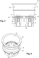
figures 3 et 4 illustrent, respectivement en vue de face et en perspective de dessus, une partie du dispositif d'assemblage desfigures 1 et 2 , - et la
figure 5 montre en détails la zone nommée A et repérée en pointillés sur lafigure 3 . - Sur les
figures 1 à 5 présentées sommairement ci-avant, il est représenté un exemple de dispositif d'assemblage 10 selon l'invention. Le dispositif d'assemblage 10 permet d'assembler un premier support 100 et un deuxième support 200 entre eux dans une configuration où le premier support 100 et le deuxième support 200 sont superposés au moins localement, c'est-à-dire au moins au niveau du dispositif d'assemblage 10 qui les maintient assemblés l'un à l'autre. En étant assemblés l'un à l'autre au moyen d'un ou plusieurs dispositifs d'assemblage 10, les deux supports 100, 200 ont pour fonction de séparer un premier environnement E1 et un deuxième environnement E2 l'un de l'autre. - La nature du premier support 100 et celle du deuxième support 200 ne sont pas vraiement limitatives en soi et, au contraire, le lecteur pourra envisager d'utiliser le dispositif d'assemblage 10 décrit dans ce document dans le cadre de nombreux domaines d'application.
- Dans un domaine particulier d'application particulièrement visé par le dispositif d'assemblage 10, mais une fois encore non limitatif, les deux supports 100, 200 ont pour fonction de séparer et d'isoler thermiquement et de manière phonique un premier environnement E1 correspondant à un compartiment moteur d'un véhicule automobile par rapport à un deuxième environnement E2 correspondant à un habitacle du véhicule automobile. Il est recherché de limiter autant que possible les transferts de chaleur, de bruits et de vibrations mécaniques du premier environnement E1 vers le deuxième environnement E2.
- Le premier support 100 peut typiquement se présenter sous la forme d'une paroi configurée pour remplir une fonction structurelle avec des propriétés idoines de rigidité et de résistance mécanique, par exemple sous la forme d'une tôle métallique. Le deuxième support 200 peut se présenter sous la forme d'un panneau isolant ayant des propriétés d'isolation thermique et/ou phonique et présentant par exemple une épaisseur 201 supérieure à l'épaisseur 101 du premier support 100 dans la zone au niveau de laquelle ils sont destinés à être assemblés grâce au dispositif d'assemblage 10.
- Le dispositif d'assemblage 10 comprend un corps d'obturation 20, essentiellement sous la forme d'un fût creux, s'étendant essentiellement selon un axe principal X et configuré de sorte à pouvoir venir obturer une ouverture 102 formée dans le premier support 100 par insertion de tout ou partie du corps d'obturation 20 dans l'ouverture 102 par un déplacement du corps d'obturation 20 orienté sensiblement parallèlement à l'axe principal X. La section du corps d'obturation 20 est complémentaire de la forme de l'ouverture, moyennant toutefois l'interposition d'un jeu fonctionnel entre les deux afin de permettre l'insertion du corps d'obturation 20 dans l'ouverture.
- Dans ce document, le terme « sensiblement parallèlement » s'interprète comme signifiant soit « exactement parallèle », soit « parallèle à 10° près ».
- Le dispositif d'assemblage 10 comprend également une entretoise 30 solidaire indirectement du corps d'obturation 20 comme il le sera expliqué plus loin, et moyennant un décalage entre eux suivant l'axe principal X. Dans la variante représentée, l'entretoise 30 est alignée avec le corps d'obturation 20 le long de l'axe principal X, mais ces dispositions ne sont pas limitatives car il peut être envisagé un décalage entre l'entretoise 30 et le corps d'obturation 20 transversalement à l'axe principal X.
- L'entretoise 30 est destinée à traverser toute l'épaisseur 201 du deuxième support 200. L'entretoise 30 permet d'éviter un écrasement local du deuxième support 200 lorsqu'il est maintenu par le dispositif d'assemblage 10 et assemblé au premier support 100. Selon un mode de réalisation non limitatif, l'entretoise 30 comprend un fût 31 creux s'étendant le long de l'axe principal X ou parallèlement à celui-ci. Ce fût 31, qui est par exemple de forme légèrement conique en diminuant de diamètre en s'approchant du corps d'obturation 20, est destiné à être à être inséré dans un orifice 202 formé dans le deuxième support 200 par un déplacement du fût 31 sensiblement parallèlement à l'axe principal X jusqu'à traverser toute l'épaisseur 201 du deuxième support 200.
- L'entretoise 30 comprend des éléments d'appui aptes à venir en appui contre le deuxième support 200 suivant l'axe principal X du côté opposé au corps d'obturation 20, pour maintenir le deuxième support 200 dans une configuration (représentée sur la
figure 2 ) où le premier support 100 et le deuxième support 200 sont situés l'un au-dessus de l'autre suivant l'axe principal X au moins au niveau du dispositif d'assemblage 10. Ces éléments d'appui solidaires de l'entretoise 30 sont destinés à venir en appui contre le deuxième support 200 suivant l'axe principal X pour former une butée pour le deuxième support 200 le long de l'axe principal X dans un sens tendant à s'opposer à un éloignement du deuxième support 200 par rapport au corps d'obturation 20 suivant l'axe principal X, et donc à s'opposer à un éloignement du deuxième support 200 par rapport au premier support 100 lui-même fixé au corps d'obturation 20 de la manière qui sera décrite plus loin. - Selon un mode de réalisation tel qu'illustré mais qui reste non limitatif, les éléments d'appui comprennent une tête supérieure 32 s'étendant en saillie transversalement à l'axe principal X autour du fût 31 et présentant des dimensions extérieures, vues dans un plan orthogonal P à l'axe principal X, strictement supérieures aux dimensions de la section de l'orifice 202 formé dans le deuxième support 200.
- Par exemple, pour conférer un maintien efficace du deuxième support 200 et une étanchéité efficace tout en facilitant la mise en place en limitant les risques de mauvais positionnement du dispositif d'assemblage 10, facilitant ainsi une mise en place intuitive et potentiellement en aveugle, la tête supérieure 32 peut se présenter sous la forme d'une collerette annulaire s'étendant radialement en saillie de l'ensemble du pourtour de l'entretoise 30. Il reste toutefois que la tête supérieure 32 peut présenter toute autre forme, potentiellement en saillie radialement autour du fût 31 de manière discontinue angulairement ou non.
- Selon un mode de réalisation non limitatif, les éléments d'appui solidaires de l'entretoise 30 comprennent un joint supérieur d'étanchéité 33 en matière élastomère déformable solidaire de la tête supérieure 32 et agencé pour venir en appui contre le deuxième support 200 lorsque celui-ci est maintenu par les éléments d'appui solidaires de l'entretoise 30. Le joint supérieur d'étanchéité 33, globalement annulaire, présente par exemple une forme évasée, par exemple en incluant une paroi de forme tronconique, qui augmente de diamètre et qui s'ouvre en s'approchant du corps d'obturation 20.
- Le joint supérieur d'étanchéité 33 peut être rendu solidaire de la tête supérieure 32 par une opération de surmoulage ou, alternativement, par une mise en place du joint supérieur d'étanchéité 33 par emboitement sur la tête supérieure 32. Dans ce dernier cas, la tête supérieure 32 et le joint supérieur d'étanchéité 33 sont respectivement équipés de premiers éléments et de seconds éléments d'un même système d'emboitement dans lequel les premiers éléments et les seconds éléments peuvent occuper un état de non coopération entre eux où la fixation du joint supérieur d'étanchéité 33 sur la tête supérieure 32 n'est pas assurée et un état de coopération où les premiers éléments et les seconds éléments coopèrent entre eux par emboitement respectif d'une manière assurant la fixation du joint supérieur d'étanchéité 33 sur la tête supérieure 32.
- Pour que l'entretoise 30 joue un rôle d'entretoisement vis-à-vis du deuxième support 200 pour éviter un écrasement local et une éventuelle détérioration, la hauteur du fût 31 le long de l'axe principal X est supérieur ou égal à l'épaisseur 201 du deuxième support 200 au niveau de l'orifice 202. Le bord inférieur du joint supérieur d'étanchéité 33 est destiné à venir en appui contre le deuxième support 200 de manière étanche. Cette mise en appui étanche peut s'accompagner d'une compression du joint supérieur d'étanchéité 33 suivant l'axe principal X éventuellement concomitante à un rapprochement du bord inférieur du joint supérieur d'étanchéité 33 vers la tête supérieure 32.
- L'étanchéité conférée par le joint supérieur d'étanchéité 33 s'entend à la fois d'une étanchéité aux fluides (que ce soit sous forme liquide ou gaz, en fonction de la nature des environnements E1, E2) susceptibles d'être présents à travers l'orifice 202 et d'une étanchéité sonore.
- En complément, de manière importante, le dispositif d'assemblage 10 comprend un système de liaison 40 reliant mécaniquement le corps d'obturation 20 et l'entretoise 30. Le système de liaison 40 est configuré pour présenter une aptitude à se déformer élastiquement le long de l'axe principal X d'une manière conférant une liaison mécanique élastiquement déformable et amortissante entre le corps d'obturation 20 et l'entretoise 30 suivant l'axe principal X. Le système de liaison 40 est essentiellement configuré de sorte que la liaison mécanique qu'il confère est telle que, sous l'effet d'efforts extérieurs susceptibles d'être appliqués au dispositif d'assemblage 10 par le premier support 100 et par le deuxième support 200 respectivement au niveau du corps d'obturation 20 et de l'entretoise 30, le corps d'obturation 20 et l'entretoise 30 ont une aptitude à se rapprocher élastiquement l'un de l'autre suivant l'axe principal X tout en amortissant les vibrations mécaniques.
- Le dispositif d'assemblage 10 permet de limiter considérablement les vibrations mécaniques entre le corps d'obturation 20 et l'entretoise 30, ce qui permet au final de limiter d'autant le transfert de vibrations mécaniques de l'environnement E1 délimité et isolé par les deux supports 100, 200 à l'autre environnement E2 délimité et isolé par les deux supports 100, 200.
- Pour limiter la quantité de matière et l'encombrement du dispositif d'assemblage 10, il peut être avantageux de prévoir que la tête supérieure 32 soit agencée à une extrémité distale de l'entretoise 30. L'extrémité distale est l'extrémité opposée suivant l'axe principal X à une extrémité proximale de l'entretoise 30 qui correspond à l'extrémité tournée du côté du corps d'obturation 20 et directement reliée mécaniquement au système de liaison 40.
- Dans un mode de réalisation particulier mais non limitatif, le corps d'obturation 20 comprend au moins une patte d'encliquetage 21 destinée à assurer une fixation par encliquetage entre le corps d'obturation 20 et le premier support 100. La combinaison de la fixation par encliquetage du premier support 100 au corps d'obturation 20 et du maintien du deuxième support 200 par appui par l'entretoise 30 permet d'assurer l'assemblage recherché des deux supports 100, 200.
- Chacune des pattes d'encliquetage 21 comprend un ergot de retenue 22 destiné à venir automatiquement s'accrocher sur le contour de l'ouverture 102 formée dans le premier support 100 de manière à conférer l'état assurant la fixation par encliquetage entre le corps d'obturation 20 et le premier support 100. Cet accrochage de l'ergot de retenue 22 résulte automatiquement d'un mouvement d'insertion du corps d'obturation 20 dans l'ouverture 102 suivant une course d'insertion supérieure ou égale à une valeur prédéterminée. Tant que la course d'insertion du corps d'obturation 20 reste inférieure à la valeur prédéterminée, l'état assurant la fixation par encliquetage n'est pas occupé.
- Comme cela est visible sur les figures, chaque patte d'encliquetage 21 se présente par exemple sous la forme d'une languette flexible avec une aptitude à se déformer transversalement à l'axe principal X. Chaque patte d'encliquetage 21 est reliée par son extrémité proximale au reste du corps d'obturation 20 à proximité de l'extrémité distale du corps d'obturation 20. L'extrémité distale du corps d'obturation 20 correspond à l'extrémité opposée, suivant l'axe principal X, à l'extrémité proximale du corps d'obturation 20 qui est tournée du côté de l'entretoise 30 et directement reliée mécaniquement au système de liaison 40. Chaque patte d'encliquetage 21 s'étend librement sensiblement parallèlement à l'axe principal X. L'ergot de retenue 22 est agencé à proximité de l'extrémité distale de la patte d'encliquetage 21 et est apte à venir en appui contre la face arrière du premier support 100, qui est la face opposée à la face avant du premier support 100 contre laquelle une tête inférieure 23 du corps d'obturation 20 vient en appui à l'issue de la course d'insertion supérieure ou égale à la valeur prédéterminée. L'aptitude de chaque patte d'encliquetage 21 à se déformer élastiquement résulte d'une aptitude de la patte d'encliquetage 21 à se déformer en flexion sur sa longueur et/ou d'une aptitude de la zone de raccordement de la patte d'encliquetage 21 au reste du corps d'obturation 20 à se déformer élastiquement en torsion. La distance comptée suivant l'axe principal X séparant le cran d'appui délimité par l'ergot de retenue 22 et la tête inférieure 23 est supérieure ou égale à l'épaisseur 101 locale du premier support 100.
- Selon un mode de réalisation non limitatif, la tête inférieure 23 s'étend en saillie transversalement à l'axe principal X autour du reste du corps d'obturation 20. La tête inférieure 23 présente des dimensions extérieures, considérées dans le plan orthogonal P à l'axe principal X, supérieures aux dimensions de la section de l'ouverture 102 formée dans le premier support 100. La tête inférieure 23 est destinée à venir en appui contre le premier support 100 suivant l'axe principal X, au niveau de sa face avant précédemment évoquée, pour former une butée pour le premier support 100 le long de l'axe principal X dans un sens tendant à s'opposer à un rapprochement du premier support 100 vers l'entretoise 30 suivant l'axe principal X, et donc à s'opposer à un rapprochement du premier support 100 en direction du deuxième support 200 lui-même maintenu axialement par les éléments d'appui solidaires de l'entretoise 30.
- Par exemple, pour conférer un appui efficace de la tête inférieure 23 sur le premier support 100 et une obturation efficace et étanche de l'ouverture 102 par le corps d'obturation 20 tout en facilitant la mise en place en limitant les risques de mauvais positionnement du dispositif d'assemblage 10, facilitant d'autant une mise en place intuitive et potentiellement en aveugle, la tête inférieure 23 peut se présenter sous la forme d'une collerette annulaire s'étendant radialement en saillie autour du corps d'obturation 20. Il reste toutefois que la tête inférieure 23 peut présenter toute autre forme, potentiellement en saillie radialement autour du corps d'obturation 20 de manière discontinue angulairement ou non.
- Pour limiter la quantité de matière et l'encombrement du dispositif d'assemblage 10, il peut être avantageux de prévoir que la tête inférieure 23 soit agencée au niveau de l'extrémité proximale du corps d'obturation 20 suivant l'axe principal X.
- Selon un mode de réalisation non limitatif, le dispositif d'assemblage 10 comprend un joint inférieur d'étanchéité 24 en matière élastomère déformable solidaire de la tête inférieure 23 et agencé pour venir en appui contre le premier support 100 lorsque le corps d'obturation 20 obture l'ouverture 102 formée dans le premier support 100, notamment lorsque le corps d'obturation 20 est fixé par encliquetage dans l'ouverture 102 du premier support 102.
- Le joint inférieur d'étanchéité 24, globalement annulaire, présente par exemple une forme évasée, par exemple en incluant une paroi de forme tronconique, qui augmente de diamètre et qui s'ouvre en s'approchant de l'extrémité distale du corps d'obturation 20.
- Le joint inférieur d'étanchéité 24 peut être rendu solidaire de la tête inférieure 23 par une opération de surmoulage ou, alternativement, par une mise en place du joint inférieur d'étanchéité 24 par emboitement sur la tête inférieure 23. Dans ce dernier cas, la tête inférieure 23 et le joint inférieur d'étanchéité 24 sont respectivement équipés de premiers éléments et de seconds éléments d'un même système d'emboitement dans lequel les premiers éléments et les seconds éléments peuvent occuper un état de non coopération entre eux où la fixation du joint inférieur d'étanchéité 24 sur la tête inférieure 23 n'est pas assurée ou un état de coopération où les premiers éléments et les seconds éléments coopèrent entre eux par emboitement respectif d'une manière assurant la fixation du joint inférieur d'étanchéité 24 sur la tête inférieure 23.
- Le bord inférieur du joint inférieur d'étanchéité 24 est destiné à venir en appui contre le premier support 100 de manière étanche. Cette mise en appui étanche peut s'accompagner d'une compression du joint inférieur d'étanchéité 24 suivant l'axe principal X concomitante à un rapprochement du bord inférieur du joint inférieur d'étanchéité 24 vers la tête inférieure 23. Ce phénomène est schématisé sur la
figure 2 qui montre que le joint inférieur d'étanchéité 24 présente une hauteur suivant l'axe principal X ayant une valeur inférieure à celle occupée par le joint inférieur d'étanchéité 24, par exemple sur lafigure 1 , lorsque celui-ci n'est pas soumis à une compression. - L'étanchéité conférée par le joint inférieur d'étanchéité 24 s'entend à la fois d'une étanchéité aux fluides (que ce soit sous forme liquide ou gaz, en fonction de la nature des environnements E1, E2) susceptibles d'être présents à travers l'ouverture 102 et d'une étanchéité sonore.
- Selon un mode de réalisation non limitatif, le système de liaison 40 comprend une pluralité de liens 41 individuels distincts les uns des autres. Chaque lien 41 relie mécaniquement l'extrémité proximale du corps d'obturation 20 et l'extrémité proximale de l'entretoise 30. Chaque lien 41 est positionné dans une zone donnée du pourtour de l'entretoise 30, ce pourtour étant considéré dans le plan orthogonal P à l'axe principal X et dans une zone donnée du pourtour du corps d'obturation 20, ce pourtour étant considéré également dans le plan orthogonal P à l'axe principal X.
- Chaque lien 41 est configuré, notamment par une adaptation de sa matière constitutive, de sa section de coupe le long de sa longueur et de la forme suivant laquelle il s'étend, de telle manière que tout ou partie de chaque lien 41 est déformable élastiquement au moins suivant l'axe principal X. Cette aptitude de déformation propre à chaque lien 41 et combinée pour l'ensemble des liens 41 présents permet de fournir un système de liaison 40 ayant les propriétés avantageuses précédemment décrites.
- A cet effet, comme cela est détaillé sur la
figure 5 , chaque lien 41 est notamment constitué d'un tenon inférieur 411 raccordé mécaniquement au corps d'obturation 20, d'un tenon supérieur 412 raccordé mécaniquement à l'entretoise 30 et d'une branche de raccordement 413 reliant mécaniquement le tenon inférieur 411 et le tenon supérieur 412 entre eux. Le tenon inférieur 411 et le tenon supérieur 412 s'étendent chacun sensiblement parallèlement à l'axe principal X en présentant un décalage Ω l'un par rapport à l'autre transversalement à l'axe principal X. La branche de raccordement 413 est avantageusement inclinée par rapport au plan orthogonal P à l'axe principal X de sorte que l'angle α formé entre la branche de raccordement 413 et le plan orthogonal P est strictement différent de 0°. - La déformation élastique de chaque lien 41 suivant l'axe principal X est obtenue par la combinaison d'une capacité de la branche de raccordement 413 à se déformer élastiquement suivant sa longueur par flexion, d'une capacité de la zone de jonction entre la branche de raccordement 413 et le tenon supérieur 412 à se déformer élastiquement par torsion à la manière d'une articulation, et d'une capacité de la zone de jonction entre la branche de raccordement 413 et le tenon inférieur 411 à se déformer élastiquement par torsion à la manière d'une articulation
- Selon un mode de réalisation non limitatif, l'angle α formé entre la branche de raccordement 413 et le plan orthogonal P à l'axe principal X est très avantageusement compris entre 10° et 25°, de préférence entre 15° et 20°. En effet, il a été déterminé par la Demanderesse, de manière empirique et par simulation numérique, que la présence d'un angle α ayant une telle valeur permet de conférer une très bonne aptitude de chaque lien 41 à se déformer élastiquement et permet au système de liaison 40 de jouer pleinement sa fonction générale d'amortissement de vibrations mécaniques telle que décrite précédemment. A titre d'exemple non limitatif, de la manière illustrée sur les figures, l'angle α est égal à 17°.
- Pour garantir un fonctionnement fiable et efficace du système de liaison 40, il est notamment important de prévoir que le nombre de liens 41 soit supérieur ou égal à 2 et que les liens 41 soient répartis autour de l'axe principal X, le long des pourtours du corps d'obturation 20 et de l'entretoise 30, selon une répartition angulaire à intervalles réguliers ou non. Dans le cas où le nombre de liens 41 est pair, par exemple égal à 4 comme c'est le cas dans l'exemple particulier non limitatif des
figures 1 à 5 , les liens 41 peuvent alors être répartis par paires en prévoyant que les deux liens 41 d'une même paire soient disposés en regard l'un de l'autre suivant une direction radiale perpendiculaire à l'axe principal X. - Dans un mode de réalisation particulier non limitatif tel que représenté, le corps d'obturation 20, l'entretoise 30 et le système de liaison 40 sont formés dans une pièce unique monobloc, c'est-à-dire d'un seul tenant, typiquement obtenue dans une matière plastique, par exemple par des opérations de moulage. Il peut aussi s'agir d'une pièce métallique. Le joint supérieur d'étanchéité 33 et le joint inférieur d'étanchéité 24 peuvent être des pièces indépendantes de la pièce unique monobloc susmentionnée et rapportées à cette dernière de manière démontable ou à demeure, par exemple respectivement par un principe d'emboitement ou par un principe de surmoulage comme cela l'a déjà été expliqué.
Claims (9)
- Dispositif d'assemblage (10) destiné à assembler un premier support (100) et un deuxième support (200) entre eux dans une configuration où les supports (100, 200) sont superposés au moins localement, le dispositif d'assemblage (10) comprenant :un corps d'obturation (20) s'étendant essentiellement selon un axe principal (X) et configuré de sorte à pouvoir venir se fixer dans une ouverture (102) formée dans le premier support (100) tout en l'obturant, par insertion de tout ou partie du corps d'obturation (20) dans l'ouverture (102) sensiblement parallèlement à l'axe principal (X),une entretoise (30) décalée par rapport au corps d'obturation (20) suivant l'axe principal (X), destinée à traverser l'épaisseur (201) du deuxième support (200) et comprenant des éléments d'appui destinés à venir en appui contre le deuxième support (200) suivant l'axe principal (X) du côté opposé au corps d'obturation (20) pour maintenir en position le deuxième support (200) dans ladite configuration où le premier support (100) et le deuxième support (200) sont situés l'un au-dessus de l'autre suivant l'axe principal (X) au moins au niveau du dispositif d'assemblage (10),et un système de liaison (40) reliant mécaniquement le corps d'obturation (20) et l'entretoise (30) et ayant une aptitude à se déformer élastiquement le long de l'axe principal (X) d'une manière conférant une liaison mécanique élastiquement déformable et amortissante entre le corps d'obturation (20) et l'entretoise (30) suivant l'axe principal (X) telle que, sous l'effet d'efforts extérieurs susceptibles d'être appliqués au dispositif d'assemblage (10) par le premier support (100) et par le deuxième support (200) respectivement au niveau du corps d'obturation (20) et de l'entretoise (30), le corps d'obturation (20) et l'entretoise (30) ont une aptitude à se rapprocher élastiquement l'un de l'autre suivant l'axe principal (X) en jouant un rôle d'amortisseur de vibrations mécaniques.caractérisé en ce que le système de liaison (40) comprend une pluralité de liens (41) individuels distincts les uns des autres, où chaque lien (41) relie mécaniquement le corps d'obturation (20) et l'entretoise (30) et où tout ou partie de chaque lien (41) est déformable élastiquement au moins suivant l'axe principal (X), chaque lien (41) étant constitué d'une part d'un tenon inférieur (411) et d'un tenon supérieur (412) respectivement raccordés mécaniquement au corps d'obturation (20) et à l'entretoise (30) et s'étendant chacun sensiblement parallèlement à l'axe principal (X) en présentant un décalage (Ω) l'un par rapport à l'autre transversalement à l'axe principal (X), d'autre part d'une branche de raccordement (413) reliant mécaniquement le tenon inférieur (411) et le tenon supérieur (412) entre eux et étant inclinée par rapport au plan orthogonal (P) à l'axe principal (X) de sorte à former un angle (α) non nul.
- Dispositif d'assemblage (10) selon la revendication 1, caractérisé en ce que pour chaque lien (41) du système de liaison (40), l'angle (a) formé entre la branche de raccordement (413) et le plan orthogonal (P) à l'axe principal (X) est compris entre 10° et 25°, de préférence entre 15° et 20°.
- Dispositif d'assemblage (10) selon l'une quelconque des revendications 1 ou 2, caractérisé en ce que le nombre de liens (41) est supérieur ou égal à 2 et les liens (41) sont répartis autour de l'axe principal (X), chaque lien (41) étant positionné dans une zone donnée du pourtour de l'entretoise (30) vu dans le plan orthogonal (P) à l'axe principal (X) et dans une zone donnée du pourtour du corps d'obturation (20) vu dans le plan orthogonal (P) à l'axe principal (X).
- Dispositif d'assemblage (10) selon l'une quelconque des revendications 1 à 3, caractérisé en ce que le corps d'obturation (20) comprend au moins une patte d'encliquetage (21) destinée à assurer une fixation par encliquetage entre le corps d'obturation (20) et le premier support (100) et en ce que ladite au moins une patte d'encliquetage (21) comprend un ergot de retenue (22) destiné à venir automatiquement s'accrocher sur le contour de l'ouverture (102) formée dans le premier support (100) de manière à conférer l'état assurant la fixation par encliquetage entre le corps d'obturation (20) et le premier support (100), cet accrochage de l'ergot de retenue (22) résultant automatiquement d'un mouvement d'insertion du corps d'obturation (20) dans l'ouverture (102) suivant une course d'insertion supérieure ou égale à une valeur prédéterminée en dessous de laquelle ledit état n'est pas obtenu.
- Dispositif d'assemblage (10) selon l'une quelconque des revendications 1 à 4, caractérisé en ce que le corps d'obturation (20) comprend une tête inférieure (23) venant en saillie transversalement à l'axe principal (X) autour du reste du corps d'obturation (20) et présentant des dimensions extérieures, vues dans un plan orthogonal (P) à l'axe principal (X), supérieures aux dimensions de la section de l'ouverture (102) formée dans le premier support (100), la tête inférieure (23) étant destinée à venir en appui contre le premier support (100) suivant l'axe principal (X) pour former une butée pour le premier support (100) le long de l'axe principal (X) dans un sens tendant à s'opposer à un rapprochement du premier support (100) vers l'entretoise (30) suivant l'axe principal (X).
- Dispositif d'assemblage (10) selon la revendication 5, caractérisé en ce qu'il comprend un joint inférieur d'étanchéité (24) en matière élastomère déformable solidaire de la tête inférieure (23) et agencé pour venir en appui contre le premier support (100) lorsque le corps d'obturation (20) obture l'ouverture (102) formée dans le premier support (100).
- Dispositif d'assemblage (10) selon l'une des revendications 1 à 6, caractérisé en ce que l'entretoise (30) comprend un fût (31) s'étendant suivant l'axe principal (X), destiné à être à être inséré dans un orifice (202) formé dans le deuxième support (200) par un déplacement du fût (31) sensiblement parallèlement à l'axe principal (X) jusqu'à traverser toute l'épaisseur (201) du deuxième support (200) et en ce que les éléments d'appui comprennent une tête supérieure (32) venant en saillie transversalement à l'axe principal (X) autour du fût (31) et présentant des dimensions extérieures, vues dans un plan orthogonal (P) à l'axe principal (X), supérieures aux dimensions de la section de l'orifice (202) formé dans le deuxième support (200).
- Dispositif d'assemblage (10) selon la revendication 7, caractérisé en ce que les éléments d'appui solidaires de l'entretoise (30) comprennent un joint supérieur d'étanchéité (33) en matière élastomère déformable solidaire de la tête supérieure (32) et agencé pour venir en appui contre le deuxième support (200) lorsque le deuxième support (200) est maintenu par les éléments d'appui solidaires de l'entretoise (30).
- Dispositif d'assemblage (10) selon l'une quelconque des revendications 1 à 8, caractérisé en ce que le corps d'obturation (20), l'entretoise (30) et le système de liaison (40) sont formés dans une pièce unique monobloc.
Applications Claiming Priority (1)
| Application Number | Priority Date | Filing Date | Title |
|---|---|---|---|
| FR1860251A FR3088093B1 (fr) | 2018-11-07 | 2018-11-07 | Dispositif d’assemblage de deux supports superposes assurant une liaison entre les supports avec une aptitude de deplacement relatif et d’amortissement |
Publications (2)
| Publication Number | Publication Date |
|---|---|
| EP3650712A1 true EP3650712A1 (fr) | 2020-05-13 |
| EP3650712B1 EP3650712B1 (fr) | 2023-03-01 |
Family
ID=65685679
Family Applications (1)
| Application Number | Title | Priority Date | Filing Date |
|---|---|---|---|
| EP19206826.0A Active EP3650712B1 (fr) | 2018-11-07 | 2019-11-04 | Dispositif d'assemblage de deux supports superposés assurant une liaison entre les supports avec une aptitude de déplacement relatif et d'amortissement |
Country Status (3)
| Country | Link |
|---|---|
| EP (1) | EP3650712B1 (fr) |
| CN (1) | CN111152738B (fr) |
| FR (1) | FR3088093B1 (fr) |
Citations (5)
| Publication number | Priority date | Publication date | Assignee | Title |
|---|---|---|---|---|
| GB1517823A (en) * | 1975-06-11 | 1978-07-12 | Mackay Silentruba Prod Pty Ltd | Fastener |
| DE3812093A1 (de) * | 1987-07-03 | 1989-01-12 | Kitagawa Ind Co Ltd | Abstandshalter fuer platten, insbesondere fuer leiterplatten |
| US7328489B2 (en) * | 2004-07-02 | 2008-02-12 | I.T.W. De France | Fastener for fixing a panel to a support and provided with a head comprising a deformable member |
| DE102012007971A1 (de) * | 2012-04-20 | 2013-10-24 | Gm Global Technology Operations, Llc | Halteclip in einem Kraftfahrzeug |
| JP2016001041A (ja) * | 2014-06-12 | 2016-01-07 | 矢崎総業株式会社 | クランプ |
Family Cites Families (6)
| Publication number | Priority date | Publication date | Assignee | Title |
|---|---|---|---|---|
| FR2885335B1 (fr) * | 2005-05-03 | 2009-04-10 | Renault Sas | Dispositif de securite d'un vehicule automobile comprenant une fixation elastiquement deformable |
| FR3003910B1 (fr) * | 2013-03-26 | 2015-08-21 | Peugeot Citroen Automobiles Sa | Dispositif de fixation comportant un pion monte reglable dans un corps, suivant deux positions axiales |
| DE202013011533U1 (de) * | 2013-12-23 | 2015-03-24 | Böllhoff Verbindungstechnik GmbH | Ringförmige Steckkupplung sowie ein Herstellungs- und ein Verbindungsverfahren dafür |
| TW201706156A (zh) * | 2015-04-15 | 2017-02-16 | 歐拓管理股份公司 | 頂蓋、扣合固定件、固定系統、模造裝置及製造扣合固定件之方法 |
| FR3044059B1 (fr) * | 2015-11-25 | 2017-11-24 | Valeo Embrayages | Dispositif d'amortissement pendulaire |
| DE202016107350U1 (de) * | 2016-12-23 | 2018-03-28 | Lear Corporation | Gedämpfte Befestigungselementanordnung |
-
2018
- 2018-11-07 FR FR1860251A patent/FR3088093B1/fr active Active
-
2019
- 2019-11-04 EP EP19206826.0A patent/EP3650712B1/fr active Active
- 2019-11-07 CN CN201911082778.0A patent/CN111152738B/zh active Active
Patent Citations (5)
| Publication number | Priority date | Publication date | Assignee | Title |
|---|---|---|---|---|
| GB1517823A (en) * | 1975-06-11 | 1978-07-12 | Mackay Silentruba Prod Pty Ltd | Fastener |
| DE3812093A1 (de) * | 1987-07-03 | 1989-01-12 | Kitagawa Ind Co Ltd | Abstandshalter fuer platten, insbesondere fuer leiterplatten |
| US7328489B2 (en) * | 2004-07-02 | 2008-02-12 | I.T.W. De France | Fastener for fixing a panel to a support and provided with a head comprising a deformable member |
| DE102012007971A1 (de) * | 2012-04-20 | 2013-10-24 | Gm Global Technology Operations, Llc | Halteclip in einem Kraftfahrzeug |
| JP2016001041A (ja) * | 2014-06-12 | 2016-01-07 | 矢崎総業株式会社 | クランプ |
Also Published As
| Publication number | Publication date |
|---|---|
| CN111152738B (zh) | 2023-09-15 |
| EP3650712B1 (fr) | 2023-03-01 |
| FR3088093B1 (fr) | 2020-10-30 |
| CN111152738A (zh) | 2020-05-15 |
| FR3088093A1 (fr) | 2020-05-08 |
Similar Documents
| Publication | Publication Date | Title |
|---|---|---|
| EP2598785B1 (fr) | Systeme de serrage pour le raccordement et le pre-montage d'un premier et d'un deuxieme tube | |
| EP3306164B1 (fr) | Systeme de serrage a position angulaire controlee pour le raccordement de deux tubes | |
| EP1306542A1 (fr) | Filtre à air, conduit d'admission et ensemble constitué d'un filtre et d'un conduit d'admission de ce genre | |
| WO2013117840A1 (fr) | Dispositif de transmission de couple pour un vehicule automobile | |
| FR2986591A1 (fr) | Dispositif d'amortissement pendulaire pour une transmission de vehicule automobile | |
| EP2060746A1 (fr) | Vanne de décharge dans une turbomachine | |
| EP0721071B1 (fr) | Perfectionnements aux manchons de support antivibratoires hydrauliques | |
| FR2576654A1 (fr) | Dispositif amortisseur de torsion a grand debattement angulaire, notamment pour vehicule automobile | |
| EP4370408A1 (fr) | Déflecteur aérodynamique destiné à être fixé contre le soubassement de caisse d'un véhicule automobile et pourvu de moyens de pré-maintien | |
| FR2930898A1 (fr) | Element de filtre et systeme de filtre notamment pour un moteur a combustion interne | |
| FR3084709A1 (fr) | Accouplement en rotation | |
| FR3039240A1 (fr) | Double volant amortisseur comportant une rondelle d'obturation apte a assurer l'etancheite du volant primaire | |
| EP3650712B1 (fr) | Dispositif d'assemblage de deux supports superposés assurant une liaison entre les supports avec une aptitude de déplacement relatif et d'amortissement | |
| EP3455535B1 (fr) | Raccord a deconnexion par traction sur une bague | |
| FR2775509A1 (fr) | Perfectionnement a un raccord encliquetable pour conduit de fluide, en particulier pour vehicule automobile | |
| EP0496657A1 (fr) | Dispositif de montage d'un boîtier, notamment d'un appareil de chauffage et/ou de climatisation, sur la carrosserie d'un véhicule automobile | |
| EP2817198A1 (fr) | Assemblage elastique d'une machoire de joint de cardan avec un arbre de colonne de direction | |
| EP3636472A1 (fr) | Panneau de carrosserie comportant des éléments de rigidification rapportés | |
| FR2933876A1 (fr) | Element de filtre et systeme de filtre, notamment pour un moteur a combustion interne | |
| WO2015082401A1 (fr) | Conduit de liaison reliant un dispositif thermique de vehicule automobile au tablier du vehicule | |
| EP4412889A1 (fr) | Renfort de doublure d'un capot et d'un auvent de véhicule automobile | |
| FR3009252A1 (fr) | Enjoliveur pour ailes de vehicules automobiles muni d'un dispositif de fixation | |
| EP0849494B1 (fr) | Support hydroélastique notamment pour la suspension d'un groupe motopropulseur dans la caisse d'un véhicule automobile | |
| EP0686780B1 (fr) | Butée pour câble de commande | |
| EP4277811A1 (fr) | Équipement à paroi adaptée au collage d'un joint adhésif sur lui-même |
Legal Events
| Date | Code | Title | Description |
|---|---|---|---|
| PUAI | Public reference made under article 153(3) epc to a published international application that has entered the european phase |
Free format text: ORIGINAL CODE: 0009012 |
|
| STAA | Information on the status of an ep patent application or granted ep patent |
Free format text: STATUS: THE APPLICATION HAS BEEN PUBLISHED |
|
| AK | Designated contracting states |
Kind code of ref document: A1 Designated state(s): AL AT BE BG CH CY CZ DE DK EE ES FI FR GB GR HR HU IE IS IT LI LT LU LV MC MK MT NL NO PL PT RO RS SE SI SK SM TR |
|
| AX | Request for extension of the european patent |
Extension state: BA ME |
|
| STAA | Information on the status of an ep patent application or granted ep patent |
Free format text: STATUS: REQUEST FOR EXAMINATION WAS MADE |
|
| 17P | Request for examination filed |
Effective date: 20200828 |
|
| RBV | Designated contracting states (corrected) |
Designated state(s): AL AT BE BG CH CY CZ DE DK EE ES FI FR GB GR HR HU IE IS IT LI LT LU LV MC MK MT NL NO PL PT RO RS SE SI SK SM TR |
|
| GRAP | Despatch of communication of intention to grant a patent |
Free format text: ORIGINAL CODE: EPIDOSNIGR1 |
|
| STAA | Information on the status of an ep patent application or granted ep patent |
Free format text: STATUS: GRANT OF PATENT IS INTENDED |
|
| INTG | Intention to grant announced |
Effective date: 20220930 |
|
| GRAS | Grant fee paid |
Free format text: ORIGINAL CODE: EPIDOSNIGR3 |
|
| GRAA | (expected) grant |
Free format text: ORIGINAL CODE: 0009210 |
|
| STAA | Information on the status of an ep patent application or granted ep patent |
Free format text: STATUS: THE PATENT HAS BEEN GRANTED |
|
| AK | Designated contracting states |
Kind code of ref document: B1 Designated state(s): AL AT BE BG CH CY CZ DE DK EE ES FI FR GB GR HR HU IE IS IT LI LT LU LV MC MK MT NL NO PL PT RO RS SE SI SK SM TR |
|
| REG | Reference to a national code |
Ref country code: GB Ref legal event code: FG4D Free format text: NOT ENGLISH |
|
| REG | Reference to a national code |
Ref country code: CH Ref legal event code: EP Ref country code: AT Ref legal event code: REF Ref document number: 1551161 Country of ref document: AT Kind code of ref document: T Effective date: 20230315 |
|
| REG | Reference to a national code |
Ref country code: DE Ref legal event code: R096 Ref document number: 602019025777 Country of ref document: DE |
|
| REG | Reference to a national code |
Ref country code: IE Ref legal event code: FG4D Free format text: LANGUAGE OF EP DOCUMENT: FRENCH |
|
| REG | Reference to a national code |
Ref country code: LT Ref legal event code: MG9D |
|
| P01 | Opt-out of the competence of the unified patent court (upc) registered |
Effective date: 20230526 |
|
| REG | Reference to a national code |
Ref country code: NL Ref legal event code: MP Effective date: 20230301 |
|
| PG25 | Lapsed in a contracting state [announced via postgrant information from national office to epo] |
Ref country code: RS Free format text: LAPSE BECAUSE OF FAILURE TO SUBMIT A TRANSLATION OF THE DESCRIPTION OR TO PAY THE FEE WITHIN THE PRESCRIBED TIME-LIMIT Effective date: 20230301 Ref country code: NO Free format text: LAPSE BECAUSE OF FAILURE TO SUBMIT A TRANSLATION OF THE DESCRIPTION OR TO PAY THE FEE WITHIN THE PRESCRIBED TIME-LIMIT Effective date: 20230601 Ref country code: LV Free format text: LAPSE BECAUSE OF FAILURE TO SUBMIT A TRANSLATION OF THE DESCRIPTION OR TO PAY THE FEE WITHIN THE PRESCRIBED TIME-LIMIT Effective date: 20230301 Ref country code: LT Free format text: LAPSE BECAUSE OF FAILURE TO SUBMIT A TRANSLATION OF THE DESCRIPTION OR TO PAY THE FEE WITHIN THE PRESCRIBED TIME-LIMIT Effective date: 20230301 Ref country code: HR Free format text: LAPSE BECAUSE OF FAILURE TO SUBMIT A TRANSLATION OF THE DESCRIPTION OR TO PAY THE FEE WITHIN THE PRESCRIBED TIME-LIMIT Effective date: 20230301 Ref country code: ES Free format text: LAPSE BECAUSE OF FAILURE TO SUBMIT A TRANSLATION OF THE DESCRIPTION OR TO PAY THE FEE WITHIN THE PRESCRIBED TIME-LIMIT Effective date: 20230301 |
|
| REG | Reference to a national code |
Ref country code: AT Ref legal event code: MK05 Ref document number: 1551161 Country of ref document: AT Kind code of ref document: T Effective date: 20230301 |
|
| PG25 | Lapsed in a contracting state [announced via postgrant information from national office to epo] |
Ref country code: SE Free format text: LAPSE BECAUSE OF FAILURE TO SUBMIT A TRANSLATION OF THE DESCRIPTION OR TO PAY THE FEE WITHIN THE PRESCRIBED TIME-LIMIT Effective date: 20230301 Ref country code: PL Free format text: LAPSE BECAUSE OF FAILURE TO SUBMIT A TRANSLATION OF THE DESCRIPTION OR TO PAY THE FEE WITHIN THE PRESCRIBED TIME-LIMIT Effective date: 20230301 Ref country code: NL Free format text: LAPSE BECAUSE OF FAILURE TO SUBMIT A TRANSLATION OF THE DESCRIPTION OR TO PAY THE FEE WITHIN THE PRESCRIBED TIME-LIMIT Effective date: 20230301 Ref country code: GR Free format text: LAPSE BECAUSE OF FAILURE TO SUBMIT A TRANSLATION OF THE DESCRIPTION OR TO PAY THE FEE WITHIN THE PRESCRIBED TIME-LIMIT Effective date: 20230602 Ref country code: FI Free format text: LAPSE BECAUSE OF FAILURE TO SUBMIT A TRANSLATION OF THE DESCRIPTION OR TO PAY THE FEE WITHIN THE PRESCRIBED TIME-LIMIT Effective date: 20230301 |
|
| PG25 | Lapsed in a contracting state [announced via postgrant information from national office to epo] |
Ref country code: SM Free format text: LAPSE BECAUSE OF FAILURE TO SUBMIT A TRANSLATION OF THE DESCRIPTION OR TO PAY THE FEE WITHIN THE PRESCRIBED TIME-LIMIT Effective date: 20230301 Ref country code: RO Free format text: LAPSE BECAUSE OF FAILURE TO SUBMIT A TRANSLATION OF THE DESCRIPTION OR TO PAY THE FEE WITHIN THE PRESCRIBED TIME-LIMIT Effective date: 20230301 Ref country code: PT Free format text: LAPSE BECAUSE OF FAILURE TO SUBMIT A TRANSLATION OF THE DESCRIPTION OR TO PAY THE FEE WITHIN THE PRESCRIBED TIME-LIMIT Effective date: 20230703 Ref country code: EE Free format text: LAPSE BECAUSE OF FAILURE TO SUBMIT A TRANSLATION OF THE DESCRIPTION OR TO PAY THE FEE WITHIN THE PRESCRIBED TIME-LIMIT Effective date: 20230301 Ref country code: CZ Free format text: LAPSE BECAUSE OF FAILURE TO SUBMIT A TRANSLATION OF THE DESCRIPTION OR TO PAY THE FEE WITHIN THE PRESCRIBED TIME-LIMIT Effective date: 20230301 Ref country code: AT Free format text: LAPSE BECAUSE OF FAILURE TO SUBMIT A TRANSLATION OF THE DESCRIPTION OR TO PAY THE FEE WITHIN THE PRESCRIBED TIME-LIMIT Effective date: 20230301 |
|
| PG25 | Lapsed in a contracting state [announced via postgrant information from national office to epo] |
Ref country code: SK Free format text: LAPSE BECAUSE OF FAILURE TO SUBMIT A TRANSLATION OF THE DESCRIPTION OR TO PAY THE FEE WITHIN THE PRESCRIBED TIME-LIMIT Effective date: 20230301 Ref country code: IS Free format text: LAPSE BECAUSE OF FAILURE TO SUBMIT A TRANSLATION OF THE DESCRIPTION OR TO PAY THE FEE WITHIN THE PRESCRIBED TIME-LIMIT Effective date: 20230701 |
|
| REG | Reference to a national code |
Ref country code: DE Ref legal event code: R097 Ref document number: 602019025777 Country of ref document: DE |
|
| PLBE | No opposition filed within time limit |
Free format text: ORIGINAL CODE: 0009261 |
|
| STAA | Information on the status of an ep patent application or granted ep patent |
Free format text: STATUS: NO OPPOSITION FILED WITHIN TIME LIMIT |
|
| PG25 | Lapsed in a contracting state [announced via postgrant information from national office to epo] |
Ref country code: SI Free format text: LAPSE BECAUSE OF FAILURE TO SUBMIT A TRANSLATION OF THE DESCRIPTION OR TO PAY THE FEE WITHIN THE PRESCRIBED TIME-LIMIT Effective date: 20230301 Ref country code: DK Free format text: LAPSE BECAUSE OF FAILURE TO SUBMIT A TRANSLATION OF THE DESCRIPTION OR TO PAY THE FEE WITHIN THE PRESCRIBED TIME-LIMIT Effective date: 20230301 |
|
| 26N | No opposition filed |
Effective date: 20231204 |
|
| PG25 | Lapsed in a contracting state [announced via postgrant information from national office to epo] |
Ref country code: IT Free format text: LAPSE BECAUSE OF FAILURE TO SUBMIT A TRANSLATION OF THE DESCRIPTION OR TO PAY THE FEE WITHIN THE PRESCRIBED TIME-LIMIT Effective date: 20230301 |
|
| REG | Reference to a national code |
Ref country code: DE Ref legal event code: R119 Ref document number: 602019025777 Country of ref document: DE |
|
| REG | Reference to a national code |
Ref country code: CH Ref legal event code: PL |
|
| PG25 | Lapsed in a contracting state [announced via postgrant information from national office to epo] |
Ref country code: MC Free format text: LAPSE BECAUSE OF FAILURE TO SUBMIT A TRANSLATION OF THE DESCRIPTION OR TO PAY THE FEE WITHIN THE PRESCRIBED TIME-LIMIT Effective date: 20230301 |
|
| PG25 | Lapsed in a contracting state [announced via postgrant information from national office to epo] |
Ref country code: LU Free format text: LAPSE BECAUSE OF NON-PAYMENT OF DUE FEES Effective date: 20231104 |
|
| PG25 | Lapsed in a contracting state [announced via postgrant information from national office to epo] |
Ref country code: CH Free format text: LAPSE BECAUSE OF NON-PAYMENT OF DUE FEES Effective date: 20231130 |
|
| GBPC | Gb: european patent ceased through non-payment of renewal fee |
Effective date: 20231104 |
|
| PG25 | Lapsed in a contracting state [announced via postgrant information from national office to epo] |
Ref country code: MC Free format text: LAPSE BECAUSE OF FAILURE TO SUBMIT A TRANSLATION OF THE DESCRIPTION OR TO PAY THE FEE WITHIN THE PRESCRIBED TIME-LIMIT Effective date: 20230301 Ref country code: LU Free format text: LAPSE BECAUSE OF NON-PAYMENT OF DUE FEES Effective date: 20231104 Ref country code: CH Free format text: LAPSE BECAUSE OF NON-PAYMENT OF DUE FEES Effective date: 20231130 |
|
| REG | Reference to a national code |
Ref country code: BE Ref legal event code: MM Effective date: 20231130 |
|
| REG | Reference to a national code |
Ref country code: IE Ref legal event code: MM4A |
|
| PG25 | Lapsed in a contracting state [announced via postgrant information from national office to epo] |
Ref country code: IE Free format text: LAPSE BECAUSE OF NON-PAYMENT OF DUE FEES Effective date: 20231104 Ref country code: DE Free format text: LAPSE BECAUSE OF NON-PAYMENT OF DUE FEES Effective date: 20240601 |
|
| PG25 | Lapsed in a contracting state [announced via postgrant information from national office to epo] |
Ref country code: GB Free format text: LAPSE BECAUSE OF NON-PAYMENT OF DUE FEES Effective date: 20231104 |
|
| PG25 | Lapsed in a contracting state [announced via postgrant information from national office to epo] |
Ref country code: BE Free format text: LAPSE BECAUSE OF NON-PAYMENT OF DUE FEES Effective date: 20231130 |
|
| PG25 | Lapsed in a contracting state [announced via postgrant information from national office to epo] |
Ref country code: IE Free format text: LAPSE BECAUSE OF NON-PAYMENT OF DUE FEES Effective date: 20231104 Ref country code: GB Free format text: LAPSE BECAUSE OF NON-PAYMENT OF DUE FEES Effective date: 20231104 Ref country code: DE Free format text: LAPSE BECAUSE OF NON-PAYMENT OF DUE FEES Effective date: 20240601 Ref country code: BE Free format text: LAPSE BECAUSE OF NON-PAYMENT OF DUE FEES Effective date: 20231130 |
|
| PG25 | Lapsed in a contracting state [announced via postgrant information from national office to epo] |
Ref country code: BG Free format text: LAPSE BECAUSE OF FAILURE TO SUBMIT A TRANSLATION OF THE DESCRIPTION OR TO PAY THE FEE WITHIN THE PRESCRIBED TIME-LIMIT Effective date: 20230301 |
|
| PG25 | Lapsed in a contracting state [announced via postgrant information from national office to epo] |
Ref country code: BG Free format text: LAPSE BECAUSE OF FAILURE TO SUBMIT A TRANSLATION OF THE DESCRIPTION OR TO PAY THE FEE WITHIN THE PRESCRIBED TIME-LIMIT Effective date: 20230301 |
|
| PG25 | Lapsed in a contracting state [announced via postgrant information from national office to epo] |
Ref country code: CY Free format text: LAPSE BECAUSE OF FAILURE TO SUBMIT A TRANSLATION OF THE DESCRIPTION OR TO PAY THE FEE WITHIN THE PRESCRIBED TIME-LIMIT; INVALID AB INITIO Effective date: 20191104 |
|
| PG25 | Lapsed in a contracting state [announced via postgrant information from national office to epo] |
Ref country code: HU Free format text: LAPSE BECAUSE OF FAILURE TO SUBMIT A TRANSLATION OF THE DESCRIPTION OR TO PAY THE FEE WITHIN THE PRESCRIBED TIME-LIMIT; INVALID AB INITIO Effective date: 20191104 |
|
| PG25 | Lapsed in a contracting state [announced via postgrant information from national office to epo] |
Ref country code: TR Free format text: LAPSE BECAUSE OF FAILURE TO SUBMIT A TRANSLATION OF THE DESCRIPTION OR TO PAY THE FEE WITHIN THE PRESCRIBED TIME-LIMIT Effective date: 20230301 |
|
| PGFP | Annual fee paid to national office [announced via postgrant information from national office to epo] |
Ref country code: FR Payment date: 20251126 Year of fee payment: 7 |