EP3650156A1 - Dispositif de soudage orbital à manipulation facilitée de la mesure de l'oxygène résiduel - Google Patents
Dispositif de soudage orbital à manipulation facilitée de la mesure de l'oxygène résiduel Download PDFInfo
- Publication number
- EP3650156A1 EP3650156A1 EP18205527.7A EP18205527A EP3650156A1 EP 3650156 A1 EP3650156 A1 EP 3650156A1 EP 18205527 A EP18205527 A EP 18205527A EP 3650156 A1 EP3650156 A1 EP 3650156A1
- Authority
- EP
- European Patent Office
- Prior art keywords
- orbital welding
- welding device
- orbital
- chamber
- oxygen sensor
- Prior art date
- Legal status (The legal status is an assumption and is not a legal conclusion. Google has not performed a legal analysis and makes no representation as to the accuracy of the status listed.)
- Granted
Links
- 238000003466 welding Methods 0.000 title claims abstract description 194
- QVGXLLKOCUKJST-UHFFFAOYSA-N atomic oxygen Chemical compound [O] QVGXLLKOCUKJST-UHFFFAOYSA-N 0.000 title claims abstract description 113
- 239000001301 oxygen Substances 0.000 title claims abstract description 113
- 229910052760 oxygen Inorganic materials 0.000 title claims abstract description 113
- 238000005259 measurement Methods 0.000 title description 13
- 239000007789 gas Substances 0.000 claims abstract description 98
- 230000001681 protective effect Effects 0.000 claims abstract description 49
- 230000003287 optical effect Effects 0.000 claims description 11
- 230000008878 coupling Effects 0.000 claims description 4
- 238000010168 coupling process Methods 0.000 claims description 4
- 238000005859 coupling reaction Methods 0.000 claims description 4
- 238000000034 method Methods 0.000 description 5
- 230000035945 sensitivity Effects 0.000 description 2
- 238000012935 Averaging Methods 0.000 description 1
- 0 CC1(*)CCCCC1 Chemical compound CC1(*)CCCCC1 0.000 description 1
- 230000005540 biological transmission Effects 0.000 description 1
- 238000010926 purge Methods 0.000 description 1
Images


Classifications
-
- B—PERFORMING OPERATIONS; TRANSPORTING
- B23—MACHINE TOOLS; METAL-WORKING NOT OTHERWISE PROVIDED FOR
- B23K—SOLDERING OR UNSOLDERING; WELDING; CLADDING OR PLATING BY SOLDERING OR WELDING; CUTTING BY APPLYING HEAT LOCALLY, e.g. FLAME CUTTING; WORKING BY LASER BEAM
- B23K9/00—Arc welding or cutting
- B23K9/02—Seam welding; Backing means; Inserts
- B23K9/028—Seam welding; Backing means; Inserts for curved planar seams
- B23K9/0282—Seam welding; Backing means; Inserts for curved planar seams for welding tube sections
- B23K9/0286—Seam welding; Backing means; Inserts for curved planar seams for welding tube sections with an electrode moving around the fixed tube during the welding operation
-
- B—PERFORMING OPERATIONS; TRANSPORTING
- B23—MACHINE TOOLS; METAL-WORKING NOT OTHERWISE PROVIDED FOR
- B23K—SOLDERING OR UNSOLDERING; WELDING; CLADDING OR PLATING BY SOLDERING OR WELDING; CUTTING BY APPLYING HEAT LOCALLY, e.g. FLAME CUTTING; WORKING BY LASER BEAM
- B23K37/00—Auxiliary devices or processes, not specially adapted to a procedure covered by only one of the preceding main groups
- B23K37/02—Carriages for supporting the welding or cutting element
- B23K37/0211—Carriages for supporting the welding or cutting element travelling on a guide member, e.g. rail, track
- B23K37/0217—Carriages for supporting the welding or cutting element travelling on a guide member, e.g. rail, track the guide member being fixed to the workpiece
-
- B—PERFORMING OPERATIONS; TRANSPORTING
- B23—MACHINE TOOLS; METAL-WORKING NOT OTHERWISE PROVIDED FOR
- B23K—SOLDERING OR UNSOLDERING; WELDING; CLADDING OR PLATING BY SOLDERING OR WELDING; CUTTING BY APPLYING HEAT LOCALLY, e.g. FLAME CUTTING; WORKING BY LASER BEAM
- B23K37/00—Auxiliary devices or processes, not specially adapted to a procedure covered by only one of the preceding main groups
- B23K37/02—Carriages for supporting the welding or cutting element
- B23K37/027—Carriages for supporting the welding or cutting element for making circular cuts or welds
-
- B—PERFORMING OPERATIONS; TRANSPORTING
- B23—MACHINE TOOLS; METAL-WORKING NOT OTHERWISE PROVIDED FOR
- B23K—SOLDERING OR UNSOLDERING; WELDING; CLADDING OR PLATING BY SOLDERING OR WELDING; CUTTING BY APPLYING HEAT LOCALLY, e.g. FLAME CUTTING; WORKING BY LASER BEAM
- B23K37/00—Auxiliary devices or processes, not specially adapted to a procedure covered by only one of the preceding main groups
- B23K37/02—Carriages for supporting the welding or cutting element
- B23K37/0276—Carriages for supporting the welding or cutting element for working on or in tubes
-
- B—PERFORMING OPERATIONS; TRANSPORTING
- B23—MACHINE TOOLS; METAL-WORKING NOT OTHERWISE PROVIDED FOR
- B23K—SOLDERING OR UNSOLDERING; WELDING; CLADDING OR PLATING BY SOLDERING OR WELDING; CUTTING BY APPLYING HEAT LOCALLY, e.g. FLAME CUTTING; WORKING BY LASER BEAM
- B23K9/00—Arc welding or cutting
- B23K9/095—Monitoring or automatic control of welding parameters
- B23K9/0956—Monitoring or automatic control of welding parameters using sensing means, e.g. optical
-
- B—PERFORMING OPERATIONS; TRANSPORTING
- B23—MACHINE TOOLS; METAL-WORKING NOT OTHERWISE PROVIDED FOR
- B23K—SOLDERING OR UNSOLDERING; WELDING; CLADDING OR PLATING BY SOLDERING OR WELDING; CUTTING BY APPLYING HEAT LOCALLY, e.g. FLAME CUTTING; WORKING BY LASER BEAM
- B23K9/00—Arc welding or cutting
- B23K9/10—Other electric circuits therefor; Protective circuits; Remote controls
- B23K9/1006—Power supply
-
- B—PERFORMING OPERATIONS; TRANSPORTING
- B23—MACHINE TOOLS; METAL-WORKING NOT OTHERWISE PROVIDED FOR
- B23K—SOLDERING OR UNSOLDERING; WELDING; CLADDING OR PLATING BY SOLDERING OR WELDING; CUTTING BY APPLYING HEAT LOCALLY, e.g. FLAME CUTTING; WORKING BY LASER BEAM
- B23K9/00—Arc welding or cutting
- B23K9/16—Arc welding or cutting making use of shielding gas
-
- B—PERFORMING OPERATIONS; TRANSPORTING
- B23—MACHINE TOOLS; METAL-WORKING NOT OTHERWISE PROVIDED FOR
- B23K—SOLDERING OR UNSOLDERING; WELDING; CLADDING OR PLATING BY SOLDERING OR WELDING; CUTTING BY APPLYING HEAT LOCALLY, e.g. FLAME CUTTING; WORKING BY LASER BEAM
- B23K9/00—Arc welding or cutting
- B23K9/32—Accessories
- B23K9/325—Devices for supplying or evacuating shielding gas
- B23K9/326—Purge gas rings, i.e. devices for supplying or evacuating shielding gas inside of hollow or tubular articles, e.g. pipes, vessels
-
- B—PERFORMING OPERATIONS; TRANSPORTING
- B23—MACHINE TOOLS; METAL-WORKING NOT OTHERWISE PROVIDED FOR
- B23K—SOLDERING OR UNSOLDERING; WELDING; CLADDING OR PLATING BY SOLDERING OR WELDING; CUTTING BY APPLYING HEAT LOCALLY, e.g. FLAME CUTTING; WORKING BY LASER BEAM
- B23K2101/00—Articles made by soldering, welding or cutting
- B23K2101/04—Tubular or hollow articles
- B23K2101/06—Tubes
Definitions
- the invention relates generally to orbital welding devices with chambers for protective gas.
- WO2014130374A1 and WO2015112242A1 shows the use of oxygen sensors, in particular optical oxygen sensors, for orbital welding, partly with an oxygen sensor arranged in the chamber for protective gas.
- an orbital welding device for welding two pipe pieces, the orbital welding device having a welding current source in a welding current source housing and an orbital welding head separate from the welding current source housing and connected to the welding current source by means of a cable, the orbital welding head having a chamber for the use of protective gas, which is preferred is set up during a welding process to surround a welding electrode of the orbital welding head and essentially to close it off from the outside, and / or wherein the orbital welding device has a forming device for using protective gas, preferably root shielding gas or purge gas, the orbital welding device has an oxygen sensor, preferably for measuring an oxygen concentration in the protective gas, the oxygen sensor in or on the welding current source housing use is arranged.
- a welding device in an inventive manner, with which it is possible to measure oxygen concentrations at different locations in a simple manner, preferably with the same oxygen sensor, in particular also in the protective gas, before it has been conducted into the chamber or the interior of the tube to the connection point of the tube pieces, ie in fresh gas, because in or on the welding current source housing the oxygen sensor is centrally located and can therefore easily be used for different purposes Measurements are used.
- the oxygen sensor is preferably set up to measure an oxygen concentration in the protective gas before it has been introduced into the chamber or (preferably via the forming device in at least one of the pipe pieces to be welded) to the connection point of the pipe pieces.
- Arranged in or on the welding current source housing preferably means that the oxygen sensor is fastened there and also remains or can remain there for the intended oxygen measurements.
- the arrangement in or on the welding current source housing also facilitates handling compared to separate hand-held devices.
- an orbital welding device for welding two pipe pieces, the orbital welding device having a welding current source in a welding current source housing and an orbital welding head separate from the welding current source housing and connected to the welding current source by means of a cable, the orbital welding head having a chamber for protective gas, which is preferred is set up to surround a welding electrode of the orbital welding head and essentially to close it off from the outside during a welding process, and / or the orbital welding device has a forming device for using protective gas, preferably root protective gas or forming gas, the orbital welding device integrating one into a component of the orbital welding device Has oxygen sensor, wherein the oxygen sensor is set up to measure an oxygen concentration in the protective gas n before it has been introduced into the chamber or (preferably via the forming device in at least one of the pipe pieces to be welded) to the connection point of the pipe pieces.
- the quality of the protective gas can be determined. If, for example, the protective gas contains too much oxygen, this source of error can be found and another gas bottle can be used.
- the protective gas for forming is the same as that used for the outer tube jacket.
- the cable preferably has a minimum length of 1 m, preferably 2 m, particularly preferably 5 m.
- the welding power source is preferably stationary, while the orbital welding head is manually portable.
- a welding current source controller is preferably arranged in or on the welding current source housing.
- the orbital welding head preferably has a tube holder and a welding electrode holder, which is rotatably mounted relative to the tube holder, for holding the welding electrode.
- the orbital welding device preferably has an electric motor, preferably controlled by a motor controller, particularly preferably the welding current source controller, of the orbital welding device, which is set up to drive the welding electrode holder and thus to rotate it relative to the pipe holder.
- the pipe holder is preferably a clamp-like clamp.
- the oxygen sensor is preferably connected to the welding current source controller via a cable or via a wireless data connection for the transmission of the measurement signal or the measurement data.
- the chamber is preferably designed in such a way that the pipe pieces which are to be welded to one another are enclosed by the chamber at the ends to be connected.
- the chamber preferably has an entrance, e.g. with a hose connection for protective gas, with which the chamber can thus be filled. The previously existing air is then forced out of the chamber through the aforementioned small gaps or openings.
- the chamber can also have a dedicated gas outlet.
- the chamber is preferably designed such that the welding electrode in the chamber can be rotated around the pipe pieces to be welded.
- the orbital welding head preferably has a housing which adjoins the chamber and which forms a handle or a housing for operating or switching elements and / or the motor, for example for a user.
- the welding current source housing preferably has a gas line in or on the welding current source housing, on which the oxygen sensor is arranged so that an oxygen concentration in the gas line can be measured, the gas line being set up, a gas source (for example a gas bottle) with the chamber or the forming device to connect, or to be a part of this connection.
- a gas source for example a gas bottle
- One or more hoses are preferably arranged along the cable, which conduct the protective gas to the chamber.
- the orbital welding device in the orbital welding head or between the orbital welding head and the gas source, e.g. along the cable, a gas line on which the oxygen sensor is arranged so that an oxygen concentration in the gas line can be measured, the gas line being set up to connect a gas source (for example a gas bottle) to the chamber, or a part of this connection to be.
- a gas source for example a gas bottle
- the orbital welding device is set up to measure an oxygen concentration in the chamber by means of the oxygen sensor.
- the orbital welding device preferably has a suction device, by means of which protective gas can be sucked out of the chamber, so that the oxygen concentration can be measured therein.
- the suction device is preferably arranged in or on the welding current source housing.
- the orbital welding device preferably has an optical coupling into the chamber, which optically couples an optical oxygen sensor to the interior of the chamber, so that the oxygen concentration can be measured in the chamber.
- the orbital welding device is set up to measure an oxygen concentration in the interior of at least one of the pipe pieces to be welded by means of the oxygen sensor.
- the oxygen concentration in the interior of the tube can be direct or indirect, for example indirectly by measuring the oxygen concentration in a gas jet emerging from the tube (e.g. guided by a downstream plug with an outlet opening) - this applies to any measurement of the oxygen concentration in the interior of the tube mentioned here.
- the orbital welding device preferably has a suction device, by means of which protective gas can be sucked in from the interior of the at least one of the pipe pieces to be welded, so that the oxygen concentration can be measured therein.
- the suction device is preferably arranged in or on the welding current source housing.
- the orbital welding device preferably has an optical coupling which optically couples an optical oxygen sensor to the interior of the at least one of the pipe sections to be welded, so that the oxygen concentration can be measured inside the at least one of the pipe sections to be welded.
- the orbital welding device preferably has different light guides, one end of which is positioned at the different locations and the other end of which is focused on the sensor of the oxygen sensor, which in this case is optical.
- the orbital welding device has various suction channels or hoses and a suction device, by means of which gas samples are sucked in from the different locations to the sensor.
- the orbital welding device is preferably set up to carry out the simultaneous measurement at different locations with a higher set sensitivity than if the sensor is used to measure only at one location, so that the averaging resulting from measurement at several locations is compensated accordingly.
- the sensitivity is doubled when measuring at two locations compared to a measurement at only one location.
- the orbital welding device has a switching device which is set up to switch between a first state and at least one further state, wherein in the first state the oxygen sensor is set up to measure the oxygen concentration in the protective gas before it has been introduced into the chamber or at least one of the pipe pieces to be welded to the junction of the pipe pieces, and wherein in the at least one further state the oxygen sensor is set up, the Measure oxygen concentration in the chamber or inside at least one of the pipe pieces to be welded.
- the oxygen concentration at at least two different measuring locations can be determined with only one oxygen sensor.
- the switching device preferably has a switching valve.
- the switching device particularly preferably has an optical switching device, by means of which optical paths can be switched on and separated.
- the orbital welding device is set up, automatically as part of a welding and measuring program carried out by an electronic computer, preferably by the welding current source controller, to first switch the switching device to the first state and the oxygen concentration in the protective gas to measure before it has been introduced into the chamber or at least one of the pipe pieces to be welded to the connection point of the pipe pieces, and after a certain time to switch the switching device into the at least one further state and the oxygen concentration in the chamber or inside at least one of the to measure welding pipe pieces.
- the orbital welding device has a further oxygen sensor, the further oxygen sensor being set up to measure the oxygen concentration in the chamber or in the interior of at least one of the pipe pieces to be welded.
- the further oxygen sensor is preferably arranged in or on the orbital welding head or in or on the forming device or the gas line leading to the forming device or the orbital welding head.
- the storage device is preferably arranged in or on the welding current source housing.
- an orbital welding device for welding two pieces of pipe, the orbital welding device having a welding current source in a welding current source housing and an orbital welding head separate from the welding current source housing and connected to the welding current source by means of a cable, the orbital welding device being a forming device for using protective gas, preferably root shielding gas or forming gas, which is connected via a gas line to a gas source, the orbital welding device having an oxygen sensor, the oxygen sensor being fastened in or on the forming device or the gas line.
- protective gas preferably root shielding gas or forming gas
- the forming device preferably has at least one stopper, the oxygen sensor being fastened to a holding device of the stopper.
- the stopper preferably centrally, has a hollow rod with an external thread. Through the hollow rod, the forming gas can flow out of the pipe again when the plug is used on the downstream side.
- the plug can be squeezed by a nut on the external thread are, so that due to the enlargement of the plug diameter caused by the pinch the plug can be positioned sealingly in the pipe.
- the oxygen sensor is preferably inserted into and / or attached to the hollow rod, for example by means of an internal thread introduced into the hollow rod.
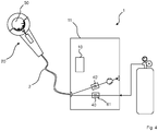
- the orbital welding device 1 has a welding current source 10 in a welding current source housing 11 and an orbital welding head 20 separate from the welding current source housing 11 and connected to the welding current source 10 by means of a cable 2, the orbital welding head 20 having a chamber 50 for protective gas, which is set up is to surround a welding electrode 23 of the orbital welding head 20 during a welding process and essentially to close off from the outside, the orbital welding device 1 optionally (dotted) having a forming device 90 for using protective gas, preferably root protective gas or forming gas, the orbital welding device 1 having one Has oxygen sensor 40, wherein the oxygen sensor 40 is arranged in or on the welding current source housing 11.
- the orbital welding device 1 has a welding current source 10 in a welding current source housing 11 and an orbital welding head 20 separate from the welding current source housing 11 and connected to the welding current source 10 by means of a cable 2, the orbital welding head 20 being a chamber 50 for protective gas which is set up to surround a welding electrode 23 of the orbital welding head 20 during a welding process and essentially to close off from the outside, the orbital welding device 1 optionally (dotted) having a forming device 90 for using protective gas, preferably root protective gas or forming gas, wherein the orbital welding device 1 has an oxygen sensor 40 integrated into another component of the orbital welding device 1, the oxygen sensor 40 being set up to measure an oxygen concentration in the protective gas before it enters the chamber 50 (or optionally also or alternatively to the connection point of the pipe pieces via the forming device 90 ) is conducted.
- the welding current source housing 11 has a gas line 61 in or on the welding current source housing 11, on which the oxygen sensor 40 is arranged such that an oxygen concentration in the gas line 61 can be measured, the gas line 61 being set up, a gas source 60 (for example a gas bottle) to be connected to the chamber 50 or optionally or alternatively to the forming device 90 or to be a part of this connection.
- a gas source 60 for example a gas bottle
- one or more hoses are arranged along the cable 2, which conduct the protective gas to the chamber 50.
- the same gas is used as the forming gas as for the protective gas in the chamber 50.
- FIG. 3a the switching device 70 is in the first state, in FIG. b in the second state.
- the configuration is such that the orbital welding device 1 is set up to measure an oxygen concentration in the chamber 50.
- the orbital welding device 1 has a suction device 80, by means of which protective gas can be sucked out of the chamber 50, so that the oxygen concentration can be measured therein.
- the configuration is such that the orbital welding device 1 has a switching device 70, which is set up to switch between a first state and a second state, wherein in the first state the oxygen sensor 40 is set up to measure the oxygen concentration in the protective gas before it enters the Chamber 50 is passed, and wherein in the second state, the oxygen sensor 40 is configured to measure the oxygen concentration in the chamber 50.
- the switching device here has a switching valve.
- the configuration is such that the orbital welding device 1 is set up to automatically switch the switching device 70 into the first state, as part of a welding and measurement program carried out by an electronic computer, here by the welding current source controller, to measure the oxygen concentration in the protective gas before it in the Chamber 50 is passed, and after a certain time to switch the switching device 70 in the second state and to measure the oxygen concentration in the chamber 50.
- FIG. 4 A more detailed description of Fig. 4 .
- the configuration is such that the orbital welding device 1 has a further oxygen sensor 40 ′, the further oxygen sensor 40 ′ being set up to measure the oxygen concentration in the chamber 50, unlike in FIG 3a and 3b .
Priority Applications (3)
| Application Number | Priority Date | Filing Date | Title |
|---|---|---|---|
| EP18205527.7A EP3650156B1 (fr) | 2018-11-09 | 2018-11-09 | Dispositif et méthode de soudage orbital à manipulation facilitée de la mesure de l'oxygène résiduel |
| PCT/US2019/059297 WO2020096872A1 (fr) | 2018-11-09 | 2019-11-01 | Dispositif de soudage orbital à manipulation plus simple de la mesure de l'oxygène résiduel |
| US17/291,066 US20210387277A1 (en) | 2018-11-09 | 2019-11-01 | Orbital welding device with simpler handling of the measurement of residual oxygen |
Applications Claiming Priority (1)
| Application Number | Priority Date | Filing Date | Title |
|---|---|---|---|
| EP18205527.7A EP3650156B1 (fr) | 2018-11-09 | 2018-11-09 | Dispositif et méthode de soudage orbital à manipulation facilitée de la mesure de l'oxygène résiduel |
Publications (2)
| Publication Number | Publication Date |
|---|---|
| EP3650156A1 true EP3650156A1 (fr) | 2020-05-13 |
| EP3650156B1 EP3650156B1 (fr) | 2023-09-06 |
Family
ID=64270758
Family Applications (1)
| Application Number | Title | Priority Date | Filing Date |
|---|---|---|---|
| EP18205527.7A Active EP3650156B1 (fr) | 2018-11-09 | 2018-11-09 | Dispositif et méthode de soudage orbital à manipulation facilitée de la mesure de l'oxygène résiduel |
Country Status (3)
| Country | Link |
|---|---|
| US (1) | US20210387277A1 (fr) |
| EP (1) | EP3650156B1 (fr) |
| WO (1) | WO2020096872A1 (fr) |
Cited By (1)
| Publication number | Priority date | Publication date | Assignee | Title |
|---|---|---|---|---|
| US20210379706A1 (en) * | 2018-11-09 | 2021-12-09 | Illinois Tool Works Inc. | Orbital welding device with improved residual oxygen measurement |
Citations (6)
| Publication number | Priority date | Publication date | Assignee | Title |
|---|---|---|---|---|
| EP0024438A1 (fr) * | 1979-03-01 | 1981-03-11 | Mitsubishi Denki Kabushiki Kaisha | Procede de soudage a l'arc |
| WO1996011765A1 (fr) * | 1994-10-18 | 1996-04-25 | Metalex A/S | Dispositif utilise pour assembler des tuyaux par soudage bout a bout |
| JP2000137023A (ja) * | 1998-11-02 | 2000-05-16 | Japan Nuclear Fuel Co Ltd<Jnf> | 溶接用不活性ガス純度計測方法及びその装置 |
| US20120140234A1 (en) * | 2009-08-10 | 2012-06-07 | Zolo Technologies, Inc. | Mitigation Of Optical Signal Noise Using A Multimode Transmit Fiber |
| DE202014100241U1 (de) * | 2014-01-21 | 2014-02-03 | Illinois Tool Works Inc. | Vorrichtung zum Messen und Sammeln von Sauerstoffkonzentrationsdaten bei Schweißprozessen |
| WO2014130374A1 (fr) | 2013-02-25 | 2014-08-28 | Illinois Tool Works Inc. | Dispositif et procédé de mesure de la teneur en oxygène dans le cadre de processus de soudure |
Family Cites Families (2)
| Publication number | Priority date | Publication date | Assignee | Title |
|---|---|---|---|---|
| US3534199A (en) * | 1968-11-12 | 1970-10-13 | Boeing Co | In-place tube welding torch |
| US3688072A (en) * | 1971-03-24 | 1972-08-29 | Weatherhead Co | Welding head inert gas supply |
-
2018
- 2018-11-09 EP EP18205527.7A patent/EP3650156B1/fr active Active
-
2019
- 2019-11-01 US US17/291,066 patent/US20210387277A1/en active Pending
- 2019-11-01 WO PCT/US2019/059297 patent/WO2020096872A1/fr active Application Filing
Patent Citations (7)
| Publication number | Priority date | Publication date | Assignee | Title |
|---|---|---|---|---|
| EP0024438A1 (fr) * | 1979-03-01 | 1981-03-11 | Mitsubishi Denki Kabushiki Kaisha | Procede de soudage a l'arc |
| WO1996011765A1 (fr) * | 1994-10-18 | 1996-04-25 | Metalex A/S | Dispositif utilise pour assembler des tuyaux par soudage bout a bout |
| JP2000137023A (ja) * | 1998-11-02 | 2000-05-16 | Japan Nuclear Fuel Co Ltd<Jnf> | 溶接用不活性ガス純度計測方法及びその装置 |
| US20120140234A1 (en) * | 2009-08-10 | 2012-06-07 | Zolo Technologies, Inc. | Mitigation Of Optical Signal Noise Using A Multimode Transmit Fiber |
| WO2014130374A1 (fr) | 2013-02-25 | 2014-08-28 | Illinois Tool Works Inc. | Dispositif et procédé de mesure de la teneur en oxygène dans le cadre de processus de soudure |
| DE202014100241U1 (de) * | 2014-01-21 | 2014-02-03 | Illinois Tool Works Inc. | Vorrichtung zum Messen und Sammeln von Sauerstoffkonzentrationsdaten bei Schweißprozessen |
| WO2015112242A1 (fr) | 2014-01-21 | 2015-07-30 | Illinois Tool Works Inc. | Dispositif de mesure et de collecte de données concernant la concentration en oxygène dans des procédés de soudage |
Cited By (1)
| Publication number | Priority date | Publication date | Assignee | Title |
|---|---|---|---|---|
| US20210379706A1 (en) * | 2018-11-09 | 2021-12-09 | Illinois Tool Works Inc. | Orbital welding device with improved residual oxygen measurement |
Also Published As
| Publication number | Publication date |
|---|---|
| EP3650156B1 (fr) | 2023-09-06 |
| WO2020096872A1 (fr) | 2020-05-14 |
| US20210387277A1 (en) | 2021-12-16 |
Similar Documents
| Publication | Publication Date | Title |
|---|---|---|
| DE4234544C2 (de) | Direkt-gekoppeltes Probenwechselsystem für Flüssigkeits-NMR-Spektroskopie und Verfahren zu dessen Betrieb | |
| DE102015106949B3 (de) | Verfahren zum Betrieb eines Geräts zur Atemgasanalyse | |
| EP0174417A1 (fr) | Sonde de prélèvement de composants volatils dans des liquides ou des gaz | |
| DE102016119713B3 (de) | Gaszuführeinheit für eine Abgasanalyseeinheit zur Messung von Abgasen von Verbrennungskraftmaschinen | |
| DE1192851B (de) | Lecksuchersonde mit einer Mischkammer | |
| EP3650156A1 (fr) | Dispositif de soudage orbital à manipulation facilitée de la mesure de l'oxygène résiduel | |
| EP3112865A1 (fr) | Dispositif d'etalonnage pour appareils d'alcool-test | |
| DE1117901B (de) | Kolorimeter-Durchflusskuevette | |
| DE102009045472A1 (de) | Sensorsystem | |
| DE60215955T2 (de) | Vorrichtung zur quantitativen analyse von atemgasen | |
| EP0301651B1 (fr) | Dispositif pour positionner un capteur | |
| DE202015009104U1 (de) | Kalibriereinrichtung für Atemalkoholmessgeräte | |
| DE102004059485A1 (de) | Lecksuchgerät | |
| DE3206337C2 (de) | Vorrichtung zur optischen Prüfung einer unter einer Isolierschicht liegenden Schweißnaht | |
| EP2224238A2 (fr) | Procédé et dispositif destinés à l'analyse élémentaire | |
| DE2127041A1 (de) | Verfahren und Vorrichtung zur Be Stimmung von Spurenelementen in festen Proben mittels optischer Emissions Spek trometne | |
| DE19812551C2 (de) | Vorrichtung zum Prüfen der mikrobiologischen Qualität eines gasförmigen Mediums | |
| AT513683B1 (de) | Kalibriereinheit für ein Abgasmessgerät | |
| DE19853900A1 (de) | Verfahren zum Einstellen der Breite des Brechspaltes bei einem Kreiselbrecher | |
| EP3650155A1 (fr) | Dispositif de soudage orbital à mesure d'oxygène résiduel améliorée | |
| WO2015140343A1 (fr) | Unité de calibrage pour un appareil de mesure des gaz d'échappement | |
| AT513681B1 (de) | Kalibriereinheit für ein Abgasmessgerät | |
| DE2236972C3 (de) | Apparatur zum Gewinnen von Proben der Abgase von mit innerer Verbrennung arbeitenden Triebwerken | |
| DE313970C (fr) | ||
| CH706490A2 (de) | Durchlauf-Mischer. |
Legal Events
| Date | Code | Title | Description |
|---|---|---|---|
| PUAI | Public reference made under article 153(3) epc to a published international application that has entered the european phase |
Free format text: ORIGINAL CODE: 0009012 |
|
| STAA | Information on the status of an ep patent application or granted ep patent |
Free format text: STATUS: THE APPLICATION HAS BEEN PUBLISHED |
|
| AK | Designated contracting states |
Kind code of ref document: A1 Designated state(s): AL AT BE BG CH CY CZ DE DK EE ES FI FR GB GR HR HU IE IS IT LI LT LU LV MC MK MT NL NO PL PT RO RS SE SI SK SM TR |
|
| AX | Request for extension of the european patent |
Extension state: BA ME |
|
| STAA | Information on the status of an ep patent application or granted ep patent |
Free format text: STATUS: REQUEST FOR EXAMINATION WAS MADE |
|
| 17P | Request for examination filed |
Effective date: 20201110 |
|
| RBV | Designated contracting states (corrected) |
Designated state(s): AL AT BE BG CH CY CZ DE DK EE ES FI FR GB GR HR HU IE IS IT LI LT LU LV MC MK MT NL NO PL PT RO RS SE SI SK SM TR |
|
| STAA | Information on the status of an ep patent application or granted ep patent |
Free format text: STATUS: EXAMINATION IS IN PROGRESS |
|
| 17Q | First examination report despatched |
Effective date: 20220422 |
|
| RIC1 | Information provided on ipc code assigned before grant |
Ipc: B23K 101/06 20060101ALN20230329BHEP Ipc: G01N 21/00 20060101ALI20230329BHEP Ipc: B23K 37/02 20060101ALI20230329BHEP Ipc: B23K 9/32 20060101ALI20230329BHEP Ipc: B23K 9/16 20060101ALI20230329BHEP Ipc: B23K 9/10 20060101ALI20230329BHEP Ipc: B23K 9/095 20060101ALI20230329BHEP Ipc: B23K 9/028 20060101AFI20230329BHEP |
|
| GRAP | Despatch of communication of intention to grant a patent |
Free format text: ORIGINAL CODE: EPIDOSNIGR1 |
|
| STAA | Information on the status of an ep patent application or granted ep patent |
Free format text: STATUS: GRANT OF PATENT IS INTENDED |
|
| RIC1 | Information provided on ipc code assigned before grant |
Ipc: B23K 101/06 20060101ALN20230428BHEP Ipc: G01N 21/00 20060101ALI20230428BHEP Ipc: B23K 37/02 20060101ALI20230428BHEP Ipc: B23K 9/32 20060101ALI20230428BHEP Ipc: B23K 9/16 20060101ALI20230428BHEP Ipc: B23K 9/10 20060101ALI20230428BHEP Ipc: B23K 9/095 20060101ALI20230428BHEP Ipc: B23K 9/028 20060101AFI20230428BHEP |
|
| INTG | Intention to grant announced |
Effective date: 20230525 |
|
| GRAS | Grant fee paid |
Free format text: ORIGINAL CODE: EPIDOSNIGR3 |
|
| GRAA | (expected) grant |
Free format text: ORIGINAL CODE: 0009210 |
|
| STAA | Information on the status of an ep patent application or granted ep patent |
Free format text: STATUS: THE PATENT HAS BEEN GRANTED |
|
| AK | Designated contracting states |
Kind code of ref document: B1 Designated state(s): AL AT BE BG CH CY CZ DE DK EE ES FI FR GB GR HR HU IE IS IT LI LT LU LV MC MK MT NL NO PL PT RO RS SE SI SK SM TR |
|
| REG | Reference to a national code |
Ref country code: GB Ref legal event code: FG4D Free format text: NOT ENGLISH |
|
| REG | Reference to a national code |
Ref country code: CH Ref legal event code: EP |
|
| P01 | Opt-out of the competence of the unified patent court (upc) registered |
Effective date: 20230821 |
|
| REG | Reference to a national code |
Ref country code: IE Ref legal event code: FG4D Free format text: LANGUAGE OF EP DOCUMENT: GERMAN |
|
| REG | Reference to a national code |
Ref country code: DE Ref legal event code: R096 Ref document number: 502018013176 Country of ref document: DE |
|
| REG | Reference to a national code |
Ref country code: NL Ref legal event code: FP |
|
| REG | Reference to a national code |
Ref country code: LT Ref legal event code: MG9D |
|
| PGFP | Annual fee paid to national office [announced via postgrant information from national office to epo] |
Ref country code: NL Payment date: 20231126 Year of fee payment: 6 |
|
| PG25 | Lapsed in a contracting state [announced via postgrant information from national office to epo] |
Ref country code: GR Free format text: LAPSE BECAUSE OF FAILURE TO SUBMIT A TRANSLATION OF THE DESCRIPTION OR TO PAY THE FEE WITHIN THE PRESCRIBED TIME-LIMIT Effective date: 20231207 |
|
| PG25 | Lapsed in a contracting state [announced via postgrant information from national office to epo] |
Ref country code: SE Free format text: LAPSE BECAUSE OF FAILURE TO SUBMIT A TRANSLATION OF THE DESCRIPTION OR TO PAY THE FEE WITHIN THE PRESCRIBED TIME-LIMIT Effective date: 20230906 Ref country code: RS Free format text: LAPSE BECAUSE OF FAILURE TO SUBMIT A TRANSLATION OF THE DESCRIPTION OR TO PAY THE FEE WITHIN THE PRESCRIBED TIME-LIMIT Effective date: 20230906 Ref country code: NO Free format text: LAPSE BECAUSE OF FAILURE TO SUBMIT A TRANSLATION OF THE DESCRIPTION OR TO PAY THE FEE WITHIN THE PRESCRIBED TIME-LIMIT Effective date: 20231206 Ref country code: LV Free format text: LAPSE BECAUSE OF FAILURE TO SUBMIT A TRANSLATION OF THE DESCRIPTION OR TO PAY THE FEE WITHIN THE PRESCRIBED TIME-LIMIT Effective date: 20230906 Ref country code: LT Free format text: LAPSE BECAUSE OF FAILURE TO SUBMIT A TRANSLATION OF THE DESCRIPTION OR TO PAY THE FEE WITHIN THE PRESCRIBED TIME-LIMIT Effective date: 20230906 Ref country code: HR Free format text: LAPSE BECAUSE OF FAILURE TO SUBMIT A TRANSLATION OF THE DESCRIPTION OR TO PAY THE FEE WITHIN THE PRESCRIBED TIME-LIMIT Effective date: 20230906 Ref country code: GR Free format text: LAPSE BECAUSE OF FAILURE TO SUBMIT A TRANSLATION OF THE DESCRIPTION OR TO PAY THE FEE WITHIN THE PRESCRIBED TIME-LIMIT Effective date: 20231207 Ref country code: FI Free format text: LAPSE BECAUSE OF FAILURE TO SUBMIT A TRANSLATION OF THE DESCRIPTION OR TO PAY THE FEE WITHIN THE PRESCRIBED TIME-LIMIT Effective date: 20230906 |
|
| PGFP | Annual fee paid to national office [announced via postgrant information from national office to epo] |
Ref country code: IT Payment date: 20231127 Year of fee payment: 6 Ref country code: IE Payment date: 20231127 Year of fee payment: 6 Ref country code: FR Payment date: 20231127 Year of fee payment: 6 Ref country code: DE Payment date: 20231129 Year of fee payment: 6 |
|
| PG25 | Lapsed in a contracting state [announced via postgrant information from national office to epo] |
Ref country code: IS Free format text: LAPSE BECAUSE OF FAILURE TO SUBMIT A TRANSLATION OF THE DESCRIPTION OR TO PAY THE FEE WITHIN THE PRESCRIBED TIME-LIMIT Effective date: 20240106 |
|
| PG25 | Lapsed in a contracting state [announced via postgrant information from national office to epo] |
Ref country code: ES Free format text: LAPSE BECAUSE OF FAILURE TO SUBMIT A TRANSLATION OF THE DESCRIPTION OR TO PAY THE FEE WITHIN THE PRESCRIBED TIME-LIMIT Effective date: 20230906 |
|
| PG25 | Lapsed in a contracting state [announced via postgrant information from national office to epo] |
Ref country code: SM Free format text: LAPSE BECAUSE OF FAILURE TO SUBMIT A TRANSLATION OF THE DESCRIPTION OR TO PAY THE FEE WITHIN THE PRESCRIBED TIME-LIMIT Effective date: 20230906 Ref country code: RO Free format text: LAPSE BECAUSE OF FAILURE TO SUBMIT A TRANSLATION OF THE DESCRIPTION OR TO PAY THE FEE WITHIN THE PRESCRIBED TIME-LIMIT Effective date: 20230906 Ref country code: IS Free format text: LAPSE BECAUSE OF FAILURE TO SUBMIT A TRANSLATION OF THE DESCRIPTION OR TO PAY THE FEE WITHIN THE PRESCRIBED TIME-LIMIT Effective date: 20240106 Ref country code: ES Free format text: LAPSE BECAUSE OF FAILURE TO SUBMIT A TRANSLATION OF THE DESCRIPTION OR TO PAY THE FEE WITHIN THE PRESCRIBED TIME-LIMIT Effective date: 20230906 Ref country code: EE Free format text: LAPSE BECAUSE OF FAILURE TO SUBMIT A TRANSLATION OF THE DESCRIPTION OR TO PAY THE FEE WITHIN THE PRESCRIBED TIME-LIMIT Effective date: 20230906 Ref country code: CZ Free format text: LAPSE BECAUSE OF FAILURE TO SUBMIT A TRANSLATION OF THE DESCRIPTION OR TO PAY THE FEE WITHIN THE PRESCRIBED TIME-LIMIT Effective date: 20230906 Ref country code: SK Free format text: LAPSE BECAUSE OF FAILURE TO SUBMIT A TRANSLATION OF THE DESCRIPTION OR TO PAY THE FEE WITHIN THE PRESCRIBED TIME-LIMIT Effective date: 20230906 Ref country code: PT Free format text: LAPSE BECAUSE OF FAILURE TO SUBMIT A TRANSLATION OF THE DESCRIPTION OR TO PAY THE FEE WITHIN THE PRESCRIBED TIME-LIMIT Effective date: 20240108 |