EP3650156A1 - Orbital welding device with easier handling of the residual oxygen measurement - Google Patents
Orbital welding device with easier handling of the residual oxygen measurement Download PDFInfo
- Publication number
- EP3650156A1 EP3650156A1 EP18205527.7A EP18205527A EP3650156A1 EP 3650156 A1 EP3650156 A1 EP 3650156A1 EP 18205527 A EP18205527 A EP 18205527A EP 3650156 A1 EP3650156 A1 EP 3650156A1
- Authority
- EP
- European Patent Office
- Prior art keywords
- orbital welding
- welding device
- orbital
- chamber
- oxygen sensor
- Prior art date
- Legal status (The legal status is an assumption and is not a legal conclusion. Google has not performed a legal analysis and makes no representation as to the accuracy of the status listed.)
- Granted
Links
- 238000003466 welding Methods 0.000 title claims abstract description 194
- QVGXLLKOCUKJST-UHFFFAOYSA-N atomic oxygen Chemical compound [O] QVGXLLKOCUKJST-UHFFFAOYSA-N 0.000 title claims abstract description 113
- 239000001301 oxygen Substances 0.000 title claims abstract description 113
- 229910052760 oxygen Inorganic materials 0.000 title claims abstract description 113
- 238000005259 measurement Methods 0.000 title description 13
- 239000007789 gas Substances 0.000 claims abstract description 98
- 230000001681 protective effect Effects 0.000 claims abstract description 49
- 230000003287 optical effect Effects 0.000 claims description 11
- 230000008878 coupling Effects 0.000 claims description 4
- 238000010168 coupling process Methods 0.000 claims description 4
- 238000005859 coupling reaction Methods 0.000 claims description 4
- 238000000034 method Methods 0.000 description 5
- 230000035945 sensitivity Effects 0.000 description 2
- 238000012935 Averaging Methods 0.000 description 1
- 0 CC1(*)CCCCC1 Chemical compound CC1(*)CCCCC1 0.000 description 1
- 230000005540 biological transmission Effects 0.000 description 1
- 238000010926 purge Methods 0.000 description 1
Images


Classifications
-
- B—PERFORMING OPERATIONS; TRANSPORTING
- B23—MACHINE TOOLS; METAL-WORKING NOT OTHERWISE PROVIDED FOR
- B23K—SOLDERING OR UNSOLDERING; WELDING; CLADDING OR PLATING BY SOLDERING OR WELDING; CUTTING BY APPLYING HEAT LOCALLY, e.g. FLAME CUTTING; WORKING BY LASER BEAM
- B23K9/00—Arc welding or cutting
- B23K9/02—Seam welding; Backing means; Inserts
- B23K9/028—Seam welding; Backing means; Inserts for curved planar seams
- B23K9/0282—Seam welding; Backing means; Inserts for curved planar seams for welding tube sections
- B23K9/0286—Seam welding; Backing means; Inserts for curved planar seams for welding tube sections with an electrode moving around the fixed tube during the welding operation
-
- B—PERFORMING OPERATIONS; TRANSPORTING
- B23—MACHINE TOOLS; METAL-WORKING NOT OTHERWISE PROVIDED FOR
- B23K—SOLDERING OR UNSOLDERING; WELDING; CLADDING OR PLATING BY SOLDERING OR WELDING; CUTTING BY APPLYING HEAT LOCALLY, e.g. FLAME CUTTING; WORKING BY LASER BEAM
- B23K37/00—Auxiliary devices or processes, not specially adapted to a procedure covered by only one of the preceding main groups
- B23K37/02—Carriages for supporting the welding or cutting element
- B23K37/0211—Carriages for supporting the welding or cutting element travelling on a guide member, e.g. rail, track
- B23K37/0217—Carriages for supporting the welding or cutting element travelling on a guide member, e.g. rail, track the guide member being fixed to the workpiece
-
- B—PERFORMING OPERATIONS; TRANSPORTING
- B23—MACHINE TOOLS; METAL-WORKING NOT OTHERWISE PROVIDED FOR
- B23K—SOLDERING OR UNSOLDERING; WELDING; CLADDING OR PLATING BY SOLDERING OR WELDING; CUTTING BY APPLYING HEAT LOCALLY, e.g. FLAME CUTTING; WORKING BY LASER BEAM
- B23K37/00—Auxiliary devices or processes, not specially adapted to a procedure covered by only one of the preceding main groups
- B23K37/02—Carriages for supporting the welding or cutting element
- B23K37/027—Carriages for supporting the welding or cutting element for making circular cuts or welds
-
- B—PERFORMING OPERATIONS; TRANSPORTING
- B23—MACHINE TOOLS; METAL-WORKING NOT OTHERWISE PROVIDED FOR
- B23K—SOLDERING OR UNSOLDERING; WELDING; CLADDING OR PLATING BY SOLDERING OR WELDING; CUTTING BY APPLYING HEAT LOCALLY, e.g. FLAME CUTTING; WORKING BY LASER BEAM
- B23K37/00—Auxiliary devices or processes, not specially adapted to a procedure covered by only one of the preceding main groups
- B23K37/02—Carriages for supporting the welding or cutting element
- B23K37/0276—Carriages for supporting the welding or cutting element for working on or in tubes
-
- B—PERFORMING OPERATIONS; TRANSPORTING
- B23—MACHINE TOOLS; METAL-WORKING NOT OTHERWISE PROVIDED FOR
- B23K—SOLDERING OR UNSOLDERING; WELDING; CLADDING OR PLATING BY SOLDERING OR WELDING; CUTTING BY APPLYING HEAT LOCALLY, e.g. FLAME CUTTING; WORKING BY LASER BEAM
- B23K9/00—Arc welding or cutting
- B23K9/095—Monitoring or automatic control of welding parameters
- B23K9/0956—Monitoring or automatic control of welding parameters using sensing means, e.g. optical
-
- B—PERFORMING OPERATIONS; TRANSPORTING
- B23—MACHINE TOOLS; METAL-WORKING NOT OTHERWISE PROVIDED FOR
- B23K—SOLDERING OR UNSOLDERING; WELDING; CLADDING OR PLATING BY SOLDERING OR WELDING; CUTTING BY APPLYING HEAT LOCALLY, e.g. FLAME CUTTING; WORKING BY LASER BEAM
- B23K9/00—Arc welding or cutting
- B23K9/10—Other electric circuits therefor; Protective circuits; Remote controls
- B23K9/1006—Power supply
-
- B—PERFORMING OPERATIONS; TRANSPORTING
- B23—MACHINE TOOLS; METAL-WORKING NOT OTHERWISE PROVIDED FOR
- B23K—SOLDERING OR UNSOLDERING; WELDING; CLADDING OR PLATING BY SOLDERING OR WELDING; CUTTING BY APPLYING HEAT LOCALLY, e.g. FLAME CUTTING; WORKING BY LASER BEAM
- B23K9/00—Arc welding or cutting
- B23K9/16—Arc welding or cutting making use of shielding gas
-
- B—PERFORMING OPERATIONS; TRANSPORTING
- B23—MACHINE TOOLS; METAL-WORKING NOT OTHERWISE PROVIDED FOR
- B23K—SOLDERING OR UNSOLDERING; WELDING; CLADDING OR PLATING BY SOLDERING OR WELDING; CUTTING BY APPLYING HEAT LOCALLY, e.g. FLAME CUTTING; WORKING BY LASER BEAM
- B23K9/00—Arc welding or cutting
- B23K9/32—Accessories
- B23K9/325—Devices for supplying or evacuating shielding gas
- B23K9/326—Purge gas rings, i.e. devices for supplying or evacuating shielding gas inside of hollow or tubular articles, e.g. pipes, vessels
-
- B—PERFORMING OPERATIONS; TRANSPORTING
- B23—MACHINE TOOLS; METAL-WORKING NOT OTHERWISE PROVIDED FOR
- B23K—SOLDERING OR UNSOLDERING; WELDING; CLADDING OR PLATING BY SOLDERING OR WELDING; CUTTING BY APPLYING HEAT LOCALLY, e.g. FLAME CUTTING; WORKING BY LASER BEAM
- B23K2101/00—Articles made by soldering, welding or cutting
- B23K2101/04—Tubular or hollow articles
- B23K2101/06—Tubes
Definitions
- the invention relates generally to orbital welding devices with chambers for protective gas.
- WO2014130374A1 and WO2015112242A1 shows the use of oxygen sensors, in particular optical oxygen sensors, for orbital welding, partly with an oxygen sensor arranged in the chamber for protective gas.
- an orbital welding device for welding two pipe pieces, the orbital welding device having a welding current source in a welding current source housing and an orbital welding head separate from the welding current source housing and connected to the welding current source by means of a cable, the orbital welding head having a chamber for the use of protective gas, which is preferred is set up during a welding process to surround a welding electrode of the orbital welding head and essentially to close it off from the outside, and / or wherein the orbital welding device has a forming device for using protective gas, preferably root shielding gas or purge gas, the orbital welding device has an oxygen sensor, preferably for measuring an oxygen concentration in the protective gas, the oxygen sensor in or on the welding current source housing use is arranged.
- a welding device in an inventive manner, with which it is possible to measure oxygen concentrations at different locations in a simple manner, preferably with the same oxygen sensor, in particular also in the protective gas, before it has been conducted into the chamber or the interior of the tube to the connection point of the tube pieces, ie in fresh gas, because in or on the welding current source housing the oxygen sensor is centrally located and can therefore easily be used for different purposes Measurements are used.
- the oxygen sensor is preferably set up to measure an oxygen concentration in the protective gas before it has been introduced into the chamber or (preferably via the forming device in at least one of the pipe pieces to be welded) to the connection point of the pipe pieces.
- Arranged in or on the welding current source housing preferably means that the oxygen sensor is fastened there and also remains or can remain there for the intended oxygen measurements.
- the arrangement in or on the welding current source housing also facilitates handling compared to separate hand-held devices.
- an orbital welding device for welding two pipe pieces, the orbital welding device having a welding current source in a welding current source housing and an orbital welding head separate from the welding current source housing and connected to the welding current source by means of a cable, the orbital welding head having a chamber for protective gas, which is preferred is set up to surround a welding electrode of the orbital welding head and essentially to close it off from the outside during a welding process, and / or the orbital welding device has a forming device for using protective gas, preferably root protective gas or forming gas, the orbital welding device integrating one into a component of the orbital welding device Has oxygen sensor, wherein the oxygen sensor is set up to measure an oxygen concentration in the protective gas n before it has been introduced into the chamber or (preferably via the forming device in at least one of the pipe pieces to be welded) to the connection point of the pipe pieces.
- the quality of the protective gas can be determined. If, for example, the protective gas contains too much oxygen, this source of error can be found and another gas bottle can be used.
- the protective gas for forming is the same as that used for the outer tube jacket.
- the cable preferably has a minimum length of 1 m, preferably 2 m, particularly preferably 5 m.
- the welding power source is preferably stationary, while the orbital welding head is manually portable.
- a welding current source controller is preferably arranged in or on the welding current source housing.
- the orbital welding head preferably has a tube holder and a welding electrode holder, which is rotatably mounted relative to the tube holder, for holding the welding electrode.
- the orbital welding device preferably has an electric motor, preferably controlled by a motor controller, particularly preferably the welding current source controller, of the orbital welding device, which is set up to drive the welding electrode holder and thus to rotate it relative to the pipe holder.
- the pipe holder is preferably a clamp-like clamp.
- the oxygen sensor is preferably connected to the welding current source controller via a cable or via a wireless data connection for the transmission of the measurement signal or the measurement data.
- the chamber is preferably designed in such a way that the pipe pieces which are to be welded to one another are enclosed by the chamber at the ends to be connected.
- the chamber preferably has an entrance, e.g. with a hose connection for protective gas, with which the chamber can thus be filled. The previously existing air is then forced out of the chamber through the aforementioned small gaps or openings.
- the chamber can also have a dedicated gas outlet.
- the chamber is preferably designed such that the welding electrode in the chamber can be rotated around the pipe pieces to be welded.
- the orbital welding head preferably has a housing which adjoins the chamber and which forms a handle or a housing for operating or switching elements and / or the motor, for example for a user.
- the welding current source housing preferably has a gas line in or on the welding current source housing, on which the oxygen sensor is arranged so that an oxygen concentration in the gas line can be measured, the gas line being set up, a gas source (for example a gas bottle) with the chamber or the forming device to connect, or to be a part of this connection.
- a gas source for example a gas bottle
- One or more hoses are preferably arranged along the cable, which conduct the protective gas to the chamber.
- the orbital welding device in the orbital welding head or between the orbital welding head and the gas source, e.g. along the cable, a gas line on which the oxygen sensor is arranged so that an oxygen concentration in the gas line can be measured, the gas line being set up to connect a gas source (for example a gas bottle) to the chamber, or a part of this connection to be.
- a gas source for example a gas bottle
- the orbital welding device is set up to measure an oxygen concentration in the chamber by means of the oxygen sensor.
- the orbital welding device preferably has a suction device, by means of which protective gas can be sucked out of the chamber, so that the oxygen concentration can be measured therein.
- the suction device is preferably arranged in or on the welding current source housing.
- the orbital welding device preferably has an optical coupling into the chamber, which optically couples an optical oxygen sensor to the interior of the chamber, so that the oxygen concentration can be measured in the chamber.
- the orbital welding device is set up to measure an oxygen concentration in the interior of at least one of the pipe pieces to be welded by means of the oxygen sensor.
- the oxygen concentration in the interior of the tube can be direct or indirect, for example indirectly by measuring the oxygen concentration in a gas jet emerging from the tube (e.g. guided by a downstream plug with an outlet opening) - this applies to any measurement of the oxygen concentration in the interior of the tube mentioned here.
- the orbital welding device preferably has a suction device, by means of which protective gas can be sucked in from the interior of the at least one of the pipe pieces to be welded, so that the oxygen concentration can be measured therein.
- the suction device is preferably arranged in or on the welding current source housing.
- the orbital welding device preferably has an optical coupling which optically couples an optical oxygen sensor to the interior of the at least one of the pipe sections to be welded, so that the oxygen concentration can be measured inside the at least one of the pipe sections to be welded.
- the orbital welding device preferably has different light guides, one end of which is positioned at the different locations and the other end of which is focused on the sensor of the oxygen sensor, which in this case is optical.
- the orbital welding device has various suction channels or hoses and a suction device, by means of which gas samples are sucked in from the different locations to the sensor.
- the orbital welding device is preferably set up to carry out the simultaneous measurement at different locations with a higher set sensitivity than if the sensor is used to measure only at one location, so that the averaging resulting from measurement at several locations is compensated accordingly.
- the sensitivity is doubled when measuring at two locations compared to a measurement at only one location.
- the orbital welding device has a switching device which is set up to switch between a first state and at least one further state, wherein in the first state the oxygen sensor is set up to measure the oxygen concentration in the protective gas before it has been introduced into the chamber or at least one of the pipe pieces to be welded to the junction of the pipe pieces, and wherein in the at least one further state the oxygen sensor is set up, the Measure oxygen concentration in the chamber or inside at least one of the pipe pieces to be welded.
- the oxygen concentration at at least two different measuring locations can be determined with only one oxygen sensor.
- the switching device preferably has a switching valve.
- the switching device particularly preferably has an optical switching device, by means of which optical paths can be switched on and separated.
- the orbital welding device is set up, automatically as part of a welding and measuring program carried out by an electronic computer, preferably by the welding current source controller, to first switch the switching device to the first state and the oxygen concentration in the protective gas to measure before it has been introduced into the chamber or at least one of the pipe pieces to be welded to the connection point of the pipe pieces, and after a certain time to switch the switching device into the at least one further state and the oxygen concentration in the chamber or inside at least one of the to measure welding pipe pieces.
- the orbital welding device has a further oxygen sensor, the further oxygen sensor being set up to measure the oxygen concentration in the chamber or in the interior of at least one of the pipe pieces to be welded.
- the further oxygen sensor is preferably arranged in or on the orbital welding head or in or on the forming device or the gas line leading to the forming device or the orbital welding head.
- the storage device is preferably arranged in or on the welding current source housing.
- an orbital welding device for welding two pieces of pipe, the orbital welding device having a welding current source in a welding current source housing and an orbital welding head separate from the welding current source housing and connected to the welding current source by means of a cable, the orbital welding device being a forming device for using protective gas, preferably root shielding gas or forming gas, which is connected via a gas line to a gas source, the orbital welding device having an oxygen sensor, the oxygen sensor being fastened in or on the forming device or the gas line.
- protective gas preferably root shielding gas or forming gas
- the forming device preferably has at least one stopper, the oxygen sensor being fastened to a holding device of the stopper.
- the stopper preferably centrally, has a hollow rod with an external thread. Through the hollow rod, the forming gas can flow out of the pipe again when the plug is used on the downstream side.
- the plug can be squeezed by a nut on the external thread are, so that due to the enlargement of the plug diameter caused by the pinch the plug can be positioned sealingly in the pipe.
- the oxygen sensor is preferably inserted into and / or attached to the hollow rod, for example by means of an internal thread introduced into the hollow rod.
- the orbital welding device 1 has a welding current source 10 in a welding current source housing 11 and an orbital welding head 20 separate from the welding current source housing 11 and connected to the welding current source 10 by means of a cable 2, the orbital welding head 20 having a chamber 50 for protective gas, which is set up is to surround a welding electrode 23 of the orbital welding head 20 during a welding process and essentially to close off from the outside, the orbital welding device 1 optionally (dotted) having a forming device 90 for using protective gas, preferably root protective gas or forming gas, the orbital welding device 1 having one Has oxygen sensor 40, wherein the oxygen sensor 40 is arranged in or on the welding current source housing 11.
- the orbital welding device 1 has a welding current source 10 in a welding current source housing 11 and an orbital welding head 20 separate from the welding current source housing 11 and connected to the welding current source 10 by means of a cable 2, the orbital welding head 20 being a chamber 50 for protective gas which is set up to surround a welding electrode 23 of the orbital welding head 20 during a welding process and essentially to close off from the outside, the orbital welding device 1 optionally (dotted) having a forming device 90 for using protective gas, preferably root protective gas or forming gas, wherein the orbital welding device 1 has an oxygen sensor 40 integrated into another component of the orbital welding device 1, the oxygen sensor 40 being set up to measure an oxygen concentration in the protective gas before it enters the chamber 50 (or optionally also or alternatively to the connection point of the pipe pieces via the forming device 90 ) is conducted.
- the welding current source housing 11 has a gas line 61 in or on the welding current source housing 11, on which the oxygen sensor 40 is arranged such that an oxygen concentration in the gas line 61 can be measured, the gas line 61 being set up, a gas source 60 (for example a gas bottle) to be connected to the chamber 50 or optionally or alternatively to the forming device 90 or to be a part of this connection.
- a gas source 60 for example a gas bottle
- one or more hoses are arranged along the cable 2, which conduct the protective gas to the chamber 50.
- the same gas is used as the forming gas as for the protective gas in the chamber 50.
- FIG. 3a the switching device 70 is in the first state, in FIG. b in the second state.
- the configuration is such that the orbital welding device 1 is set up to measure an oxygen concentration in the chamber 50.
- the orbital welding device 1 has a suction device 80, by means of which protective gas can be sucked out of the chamber 50, so that the oxygen concentration can be measured therein.
- the configuration is such that the orbital welding device 1 has a switching device 70, which is set up to switch between a first state and a second state, wherein in the first state the oxygen sensor 40 is set up to measure the oxygen concentration in the protective gas before it enters the Chamber 50 is passed, and wherein in the second state, the oxygen sensor 40 is configured to measure the oxygen concentration in the chamber 50.
- the switching device here has a switching valve.
- the configuration is such that the orbital welding device 1 is set up to automatically switch the switching device 70 into the first state, as part of a welding and measurement program carried out by an electronic computer, here by the welding current source controller, to measure the oxygen concentration in the protective gas before it in the Chamber 50 is passed, and after a certain time to switch the switching device 70 in the second state and to measure the oxygen concentration in the chamber 50.
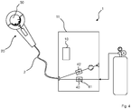
- FIG. 4 A more detailed description of Fig. 4 .
- the configuration is such that the orbital welding device 1 has a further oxygen sensor 40 ′, the further oxygen sensor 40 ′ being set up to measure the oxygen concentration in the chamber 50, unlike in FIG 3a and 3b .
Abstract
Orbitalschweißvorrichtung (1) zum Verschweißen zweier Rohrstücke, wobei die Orbitalschweißvorrichtung (1) eine Schweißstromquelle (10) in einem Schweißstromquellengehäuse (11) aufweist und einen von dem Schweißstromquellengehäuse (11) separaten, an die Schweißstromquelle (10) mittels eines Kabels (2) angeschlossenen Orbitalschweißkopf (20), wobei der Orbitalschweißkopf (20) eine Kammer (50) zur Verwendung von Schutzgas (50) aufweist und/oder die Orbitalschweißvorrichtung (1) eine Formiereinrichtung (90) zur Verwendung von Schutzgas, bevorzugt Wurzelschutzgas bzw. Formiergas, aufweist, wobei die Orbitalschweißvorrichtung (1) einen Sauerstoffsensor (40) aufweist, wobei der Sauerstoffsensor (40) in oder an dem Schweißstromquellengehäuse (11) angeordnet ist.Orbital welding device (1) for welding two pieces of pipe, the orbital welding device (1) having a welding current source (10) in a welding current source housing (11) and a separate one from the welding current source housing (11) and connected to the welding current source (10) by means of a cable (2) Orbital welding head (20), the orbital welding head (20) having a chamber (50) for using protective gas (50) and / or the orbital welding device (1) having a forming device (90) for using protective gas, preferably root shielding gas or forming gas, wherein the orbital welding device (1) has an oxygen sensor (40), the oxygen sensor (40) being arranged in or on the welding current source housing (11).
Description
Die Erfindung betrifft allgemein Orbitalschweißvorrichtungen mit Kammern für Schutzgas.The invention relates generally to orbital welding devices with chambers for protective gas.
Der Stand der Technik
Die Erfinder befanden als nachteilig, dass die Sauerstoffmessung noch nicht flexibel genug und/oder umständlich handzuhaben ist.The inventors found it disadvantageous that the oxygen measurement is not yet flexible enough and / or difficult to handle.
Die der Erfindung zu Grunde liegende Aufgabe war es, diesen Nachteil zu verbessern. Die Aufgabe wird durch die Erfindung, insbesondere wie sie in den unabhängigen Ansprüchen definiert ist, gelöst.The object underlying the invention was to improve this disadvantage. The object is achieved by the invention, in particular as defined in the independent claims.
Insbesondere wird diese Aufgabe gelöst durch eine Orbitalschweißvorrichtung zum Verschweißen zweier Rohrstücke, wobei die Orbitalschweißvorrichtung eine Schweißstromquelle in einem Schweißstromquellengehäuse aufweist und einen von dem Schweißstromquellengehäuse separaten, an die Schweißstromquelle mittels eines Kabels angeschlossenen Orbitalschweißkopf, wobei der Orbitalschweißkopf eine Kammer zur Verwendung Schutzgas aufweist, welche bevorzugt eingerichtet ist, während eines Schweißprozesses eine Schweißelektrode des Orbitalschweißkopfes zu umgeben und nach außen hin im Wesentlichen abzuschließen, und/oder wobei die Orbitalschweißvorrichtung eine Formiereinrichtung zur Verwendung von Schutzgas, bevorzugt Wurzelschutzgas bzw. Formiergas (engl. purge gas), aufweist, wobei die Orbitalschweißvorrichtung einen Sauerstoffsensor, bevorzugt zur Messung einer Sauerstoffkonzentration im Schutzgas, aufweist, wobei der Sauerstoffsensor in oder an dem Schweißstromquellengehäuse angeordnet ist.In particular, this object is achieved by an orbital welding device for welding two pipe pieces, the orbital welding device having a welding current source in a welding current source housing and an orbital welding head separate from the welding current source housing and connected to the welding current source by means of a cable, the orbital welding head having a chamber for the use of protective gas, which is preferred is set up during a welding process to surround a welding electrode of the orbital welding head and essentially to close it off from the outside, and / or wherein the orbital welding device has a forming device for using protective gas, preferably root shielding gas or purge gas, the orbital welding device has an oxygen sensor, preferably for measuring an oxygen concentration in the protective gas, the oxygen sensor in or on the welding current source housing use is arranged.
Hierdurch wird auf erfinderische Weise eine Schweißvorrichtung bereitgestellt, mit der es möglich ist in einfacher Art und Weise Sauerstoffkonzentrationen an verschiedenen Orten mit bevorzugt demselben Sauerstoffsensor zu messen, insbesondere auch im Schutzgas, bevor es in die Kammer oder das Rohrinnere zur Verbindungsstelle der Rohrstücke geleitet wurde, d.h. im Frischgas, denn in oder an dem Schweißstromquellengehäuse ist der Sauerstoffsensor zentral gelegen und kann somit einfach für verschiedene Messungen verwendet werden. Bevorzugt ist dabei der Sauerstoffsensor eingerichtet, eine Sauerstoffkonzentration im Schutzgas zu messen, bevor es in die Kammer oder (bevorzugt über die Formiereinrichtung in zumindest eines der zu verschweißenden Rohrstücke) zur Verbindungsstelle der Rohrstücke eingeleitet wurde. In oder an dem Schweißstromquellengehäuse angeordnet bedeutet bevorzugt, dass der Sauerstoffsensor dort befestigt ist und dort auch für die vorgesehenen Sauerstoffmessungen verbleibt oder verbleiben kann. Durch die Anordnung in oder an dem Schweißstromquellengehäuse wird zudem die Handhabung gegenüber separaten Handgeräten erleichtert.In this way, a welding device is provided in an inventive manner, with which it is possible to measure oxygen concentrations at different locations in a simple manner, preferably with the same oxygen sensor, in particular also in the protective gas, before it has been conducted into the chamber or the interior of the tube to the connection point of the tube pieces, ie in fresh gas, because in or on the welding current source housing the oxygen sensor is centrally located and can therefore easily be used for different purposes Measurements are used. The oxygen sensor is preferably set up to measure an oxygen concentration in the protective gas before it has been introduced into the chamber or (preferably via the forming device in at least one of the pipe pieces to be welded) to the connection point of the pipe pieces. Arranged in or on the welding current source housing preferably means that the oxygen sensor is fastened there and also remains or can remain there for the intended oxygen measurements. The arrangement in or on the welding current source housing also facilitates handling compared to separate hand-held devices.
Insbesondere wird diese Aufgabe weiterhin gelöst durch eine Orbitalschweißvorrichtung zum Verschweißen zweier Rohrstücke, wobei die Orbitalschweißvorrichtung eine Schweißstromquelle in einem Schweißstromquellengehäuse aufweist und einen von dem Schweißstromquellengehäuse separaten, an die Schweißstromquelle mittels eines Kabels angeschlossenen Orbitalschweißkopf, wobei der Orbitalschweißkopf eine Kammer für Schutzgas aufweist, welche bevorzugt eingerichtet ist, während eines Schweißprozesses eine Schweißelektrode des Orbitalschweißkopfes zu umgeben und nach außen hin im Wesentlichen abzuschließen, und/oder die Orbitalschweißvorrichtung eine Formiereinrichtung zur Verwendung von Schutzgas, bevorzugt Wurzelschutzgas bzw. Formiergas, aufweist, wobei die Orbitalschweißvorrichtung einen in eine Komponente der Orbitalschweißvorrichtung integrierten Sauerstoffsensor aufweist, wobei der Sauerstoffsensor eingerichtet ist, eine Sauerstoffkonzentration im Schutzgas zu messen, bevor es in die Kammer oder (bevorzugt über die Formiereinrichtung in zumindest eines der zu verschweißenden Rohrstücke) zur Verbindungsstelle der Rohrstücke eingeleitet wurde.In particular, this object is further achieved by an orbital welding device for welding two pipe pieces, the orbital welding device having a welding current source in a welding current source housing and an orbital welding head separate from the welding current source housing and connected to the welding current source by means of a cable, the orbital welding head having a chamber for protective gas, which is preferred is set up to surround a welding electrode of the orbital welding head and essentially to close it off from the outside during a welding process, and / or the orbital welding device has a forming device for using protective gas, preferably root protective gas or forming gas, the orbital welding device integrating one into a component of the orbital welding device Has oxygen sensor, wherein the oxygen sensor is set up to measure an oxygen concentration in the protective gas n before it has been introduced into the chamber or (preferably via the forming device in at least one of the pipe pieces to be welded) to the connection point of the pipe pieces.
Hierdurch ist die Qualität des Schutzgases bestimmbar. Wenn zum Beispiel das Schutzgas zu viel Sauerstoff enthält, kann diese Fehlerquelle gefunden werden und eine andere Gasflasche verwendet werden.In this way, the quality of the protective gas can be determined. If, for example, the protective gas contains too much oxygen, this source of error can be found and another gas bottle can be used.
Das Schutzgas zum Formieren und das Schutzgas für den Rohraußenmantel, d.h. die Kammer, können verschiedene Schutzgase, d.h. z.B. aus verschiedenen Gasflaschen, sein. Alternativ ist das Schutzgas zum Formieren dasselbe, welches auch für den Rohraußenmantel verwendet wird.The shielding gas for forming and the shielding gas for the outer pipe jacket, i.e. the chamber, various protective gases, i.e. e.g. from different gas cylinders. Alternatively, the protective gas for forming is the same as that used for the outer tube jacket.
Integriert an einer anderen Komponente bedeutet bevorzugt, dass der Sauerstoffsensor
- in oder an dem Schweißstromquellengehäuse
- oder in oder an dem Orbitalschweißkopf
- oder in oder an der Formiereinrichtung,
- oder in oder an einer Gasleitung zwischen Orbitalschweißkopf oder Formiereinrichtung und Gasquelle oder in oder an dem Kabel
- in or on the welding power source housing
- or in or on the orbital welding head
- or in or on the forming device,
- or in or on a gas line between orbital welding head or forming device and gas source or in or on the cable
Bevorzugt hat das Kabel eine Mindestlänge von 1 m, bevorzugt 2m, besonders bevorzugt 5m. Die Schweißstromquelle ist bevorzugt stationär, während der Orbitalschweißkopf manuell portabel ist. Bevorzugt ist in oder am Schweißstromquellengehäuse ein Schweißstromquellencontroller angeordnet. Bevorzugt weist der Orbitalschweißkopf eine Rohrhalterung und einen gegenüber der Rohrhalterung drehbar gelagerten Schweißelektrodenhalter zur Halterung der Schweißelektrode auf. Bevorzugt weist die Orbitalschweißvorrichtung einen, bevorzugt durch einen Motorcontroller, besonders bevorzugt den Schweißstromquellencontroller, der Orbitalschweißvorrichtung angesteuerten, bevorzugt elektrischen Motor auf, welcher eingerichtet ist, den Schweißelektrodenhalter anzutreiben und ihn so gegenüber der Rohrhalterung zu verdrehen. Die Rohrhalterung ist bevorzugt eine zangenartige Klemmhalterung.The cable preferably has a minimum length of 1 m, preferably 2 m, particularly preferably 5 m. The welding power source is preferably stationary, while the orbital welding head is manually portable. A welding current source controller is preferably arranged in or on the welding current source housing. The orbital welding head preferably has a tube holder and a welding electrode holder, which is rotatably mounted relative to the tube holder, for holding the welding electrode. The orbital welding device preferably has an electric motor, preferably controlled by a motor controller, particularly preferably the welding current source controller, of the orbital welding device, which is set up to drive the welding electrode holder and thus to rotate it relative to the pipe holder. The pipe holder is preferably a clamp-like clamp.
Der Sauerstoffsensor ist bevorzugt über ein Kabel oder über eine drahtlose Datenverbindung an den Schweißstromquellencontroller zur Übertragung des Messsignals bzw. der Messdaten angebunden.The oxygen sensor is preferably connected to the welding current source controller via a cable or via a wireless data connection for the transmission of the measurement signal or the measurement data.
Die Kammer ist bevorzugt derart ausgestaltet, dass die Rohrstücke, welche aneinandergeschweißt werden sollen, an den zu verbindenden Enden von der Kammer umschlossen sind. Die Kammer weist bevorzugt einen Eingang, z.B. mit einem Schlauchanschluss, für Schutzgas auf, mit welchem die Kammer somit gefüllt werden kann. Die vorher vorhandene Luft wird dabei dann durch die zuvor genannten kleinen Spalte oder Öffnungen aus der Kammer gedrängt. Die Kammer kann auch einen dedizierten Gasausgang aufweisen.The chamber is preferably designed in such a way that the pipe pieces which are to be welded to one another are enclosed by the chamber at the ends to be connected. The chamber preferably has an entrance, e.g. with a hose connection for protective gas, with which the chamber can thus be filled. The previously existing air is then forced out of the chamber through the aforementioned small gaps or openings. The chamber can also have a dedicated gas outlet.
Die Kammer ist bevorzugt derart gestaltet, dass die Schweißelektrode in der Kammer um die zu verschweißenden Rohrstücke gedreht werden kann.The chamber is preferably designed such that the welding electrode in the chamber can be rotated around the pipe pieces to be welded.
Bevorzugt weist der Orbitalschweißkopf ein Gehäuse auf, welches an die Kammer angrenzt und welches z.B. für einen Benutzer einen Griff oder ein Gehäuse für Bedien- oder Schaltelemente und/oder den Motor bildet.The orbital welding head preferably has a housing which adjoins the chamber and which forms a handle or a housing for operating or switching elements and / or the motor, for example for a user.
Bevorzugt weist das Schweißstromquellengehäuse in oder an dem Schweißstromquellengehäuse eine Gasleitung auf, an welcher der Sauerstoffsensor so angeordnet ist, so dass eine Sauerstoffkonzentration in der Gasleitung messbar ist, wobei die Gasleitung eingerichtet ist, eine Gasquelle (z.B. eine Gasflasche) mit der Kammer oder der Formiereinrichtung zu verbinden, bzw. ein Teilstück dieser Verbindung zu sein. Bevorzugt sind entlang des Kabels ein oder mehrere Schläuche angeordnet, welche das Schutzgas zur Kammer leiten.The welding current source housing preferably has a gas line in or on the welding current source housing, on which the oxygen sensor is arranged so that an oxygen concentration in the gas line can be measured, the gas line being set up, a gas source (for example a gas bottle) with the chamber or the forming device to connect, or to be a part of this connection. One or more hoses are preferably arranged along the cable, which conduct the protective gas to the chamber.
Alternativ oder zusätzlich weißt die Orbitalschweißvorrichtung in dem Orbitalschweißkopf oder zwischen Orbitalschweißkopf und Gasquelle, z.B. entlang des Kabels, eine Gasleitung auf, an welcher der Sauerstoffsensor so angeordnet ist, dass eine Sauerstoffkonzentration in der Gasleitung messbar ist, wobei die Gasleitung eingerichtet ist, eine Gasquelle (z.B. eine Gasflasche) mit der Kammer zu verbinden, bzw. ein Teilstück dieser Verbindung zu sein.Alternatively or additionally, the orbital welding device in the orbital welding head or between the orbital welding head and the gas source, e.g. along the cable, a gas line on which the oxygen sensor is arranged so that an oxygen concentration in the gas line can be measured, the gas line being set up to connect a gas source (for example a gas bottle) to the chamber, or a part of this connection to be.
Bei einer weiteren Orbitalschweißvorrichtung gemäß der Erfindung ist vorgesehen, dass die Orbitalschweißvorrichtung eingerichtet ist, mittels des Sauerstoffsensors eine Sauerstoffkonzentration in der Kammer zu messen.In a further orbital welding device according to the invention it is provided that the orbital welding device is set up to measure an oxygen concentration in the chamber by means of the oxygen sensor.
Bevorzugt weist die Orbitalschweißvorrichtung eine Ansaugeinrichtung auf, mittels welcher Schutzgas aus der Kammer angesaugt werden kann, so dass darin die Sauerstoffkonzentration gemessen werden kann. Die Ansaugeinrichtung ist bevorzugt in oder an dem Schweißstromquellengehäuse angeordnet.The orbital welding device preferably has a suction device, by means of which protective gas can be sucked out of the chamber, so that the oxygen concentration can be measured therein. The suction device is preferably arranged in or on the welding current source housing.
Bevorzugt weist die Orbitalschweißvorrichtung eine optische Kopplung in die Kammer auf, welche einen optischen Sauerstoffsensor mit dem Inneren der Kammer optisch koppelt, so dass in der Kammer die Sauerstoffkonzentration gemessen werden kann.The orbital welding device preferably has an optical coupling into the chamber, which optically couples an optical oxygen sensor to the interior of the chamber, so that the oxygen concentration can be measured in the chamber.
Bei einer weiteren Orbitalschweißvorrichtung gemäß der Erfindung ist vorgesehen, dass die Orbitalschweißvorrichtung eingerichtet ist, mittels des Sauerstoffsensors eine Sauerstoffkonzentration im Inneren zumindest eines der zu verschweißenden Rohrstücke zu messen. Dabei kann die Sauerstoffkonzentration im Rohrinnenraum direkt aber auch indirekt erfolgen, z.B. indirekt durch Messung der Sauerstoffkonzentration in einem aus dem Rohr austretenden (z.B. durch einen stromabwärtsseitigen Stopfen mit Austrittsöffnung geleiteten) Gasstrahl - dies gilt für jegliche hier erwähnte Messung der Sauerstoffkonzentration im Rohrinnenraum.In a further orbital welding device according to the invention it is provided that the orbital welding device is set up to measure an oxygen concentration in the interior of at least one of the pipe pieces to be welded by means of the oxygen sensor. The oxygen concentration in the interior of the tube can be direct or indirect, for example indirectly by measuring the oxygen concentration in a gas jet emerging from the tube (e.g. guided by a downstream plug with an outlet opening) - this applies to any measurement of the oxygen concentration in the interior of the tube mentioned here.
Bevorzugt weist die Orbitalschweißvorrichtung eine Ansaugeinrichtung auf, mittels welcher Schutzgas aus dem Inneren des zumindest einem der zu verschweißenden Rohrstücke angesaugt werden kann, so dass darin die Sauerstoffkonzentration gemessen werden kann. Die Ansaugeinrichtung ist bevorzugt in oder an dem Schweißstromquellengehäuse angeordnet.The orbital welding device preferably has a suction device, by means of which protective gas can be sucked in from the interior of the at least one of the pipe pieces to be welded, so that the oxygen concentration can be measured therein. The suction device is preferably arranged in or on the welding current source housing.
Bevorzugt weist die Orbitalschweißvorrichtung eine optische Kopplung auf, welche einen optischen Sauerstoffsensor mit dem Innenraum des zumindest einen der zu verschweißenden Rohrstücke optisch koppelt, so dass im Inneren des zumindest einen der zu verschweißenden Rohrstücke die Sauerstoffkonzentration gemessen werden kann.The orbital welding device preferably has an optical coupling which optically couples an optical oxygen sensor to the interior of the at least one of the pipe sections to be welded, so that the oxygen concentration can be measured inside the at least one of the pipe sections to be welded.
Bei einer weiteren Orbitalschweißvorrichtung gemäß der Erfindung ist vorgesehen, dass die Orbitalschweißvorrichtung eingerichtet ist, eine Sauerstoffkonzentration an verschiedenen Orten, gleichzeitig mittels des Sauerstoffsensors zu messen, z.B. an zwei oder mehreren der folgenden Orte
- in der Kammer, bevorzugt dort an mehreren Orten
- im Inneren zumindest eines der zu verschweißenden Rohrstücke, bevorzugt dort an mehreren Orten,
- im Schutzgas, bevor es in die Kammer oder in das Innere eines der zu verschweißenden Rohrstücke zur Verbindungsstelle der Rohrstücke strömt.
- in the chamber, preferably in several places
- inside at least one of the pipe pieces to be welded, preferably there at several locations,
- in the protective gas before it flows into the chamber or into the interior of one of the pipe pieces to be welded to the connection point of the pipe pieces.
Hierdurch ist eine kostengünstige umfassende Sauerstoffmessung möglich. Bevorzugt weist die Orbitalschweißvorrichtung verschiedene Lichtleiter auf, deren eines Ende an den verschiedenen Orten positioniert sind und deren anderes Ende auf den Sensor des in diesem Fall optischen Sauerstoffsensor gebündelt ist. Alternativ weist die Orbitalschweißvorrichtung verschiedene Ansaugkanäle oder -schläuche sowie eine Ansaugeinrichtung auf, mittels welcher Gasproben von den verschiedenen Orten zum Sensor angesaugt werden. Bevorzugt ist die Orbitalschweißvorrichtung eingerichtet, die gleichzeitige Messung an verschiedenen Orten mit einer höheren eingestellten Empfindlichkeit durchzuführen, als wenn mit dem Sensor nur an einem Ort gemessen wird, so dass die durch Messung an mehreren Orten entstehende Mittelung entsprechend kompensiert ist. Z.B. wird bei Messung an zwei Orten die Empfindlichkeit verdoppelt gegenüber einer Messung an nur einem Ort.This enables a cost-effective comprehensive oxygen measurement. The orbital welding device preferably has different light guides, one end of which is positioned at the different locations and the other end of which is focused on the sensor of the oxygen sensor, which in this case is optical. Alternatively, the orbital welding device has various suction channels or hoses and a suction device, by means of which gas samples are sucked in from the different locations to the sensor. The orbital welding device is preferably set up to carry out the simultaneous measurement at different locations with a higher set sensitivity than if the sensor is used to measure only at one location, so that the averaging resulting from measurement at several locations is compensated accordingly. E.g. the sensitivity is doubled when measuring at two locations compared to a measurement at only one location.
Bei einer weiteren Orbitalschweißvorrichtung gemäß der Erfindung ist vorgesehen, dass die Orbitalschweißvorrichtung eine Umschalteinrichtung aufweist, welche eingerichtet ist, zwischen einem ersten Zustand und mindestens einem weiteren Zustand umzuschalten, wobei in dem ersten Zustand der Sauerstoffsensor eingerichtet ist, die Sauerstoffkonzentration im Schutzgas zu messen, bevor es in die Kammer oder zumindest eines der zu verschweißenden Rohrstücke zur Verbindungsstelle der Rohrstücke eingeleitet wurde, und wobei in dem mindestens einen weiteren Zustand der Sauerstoffsensor eingerichtet ist, die Sauerstoffkonzentration in der Kammer oder im Inneren zumindest eines der zu verschweißenden Rohrstücke zu messen.In a further orbital welding device according to the invention, it is provided that the orbital welding device has a switching device which is set up to switch between a first state and at least one further state, wherein in the first state the oxygen sensor is set up to measure the oxygen concentration in the protective gas before it has been introduced into the chamber or at least one of the pipe pieces to be welded to the junction of the pipe pieces, and wherein in the at least one further state the oxygen sensor is set up, the Measure oxygen concentration in the chamber or inside at least one of the pipe pieces to be welded.
Hierdurch ist mit nur einem Sauerstoffsensor die Sauerstoffkonzentration an mindestens zwei verschiedenen Messorten bestimmbar.As a result, the oxygen concentration at at least two different measuring locations can be determined with only one oxygen sensor.
Die Umschaltvorrichtung weist bevorzugt ein Umschaltventil auf.The switching device preferably has a switching valve.
Besonders bevorzugt weist die Umschaltvorrichtung eine optische Umschaltvorrichtung auf, mittels welcher optische Pfade zugeschaltet und getrennt werden können.The switching device particularly preferably has an optical switching device, by means of which optical paths can be switched on and separated.
Bei einer weiteren Orbitalschweißvorrichtung gemäß der Erfindung ist vorgesehen, dass die Orbitalschweißvorrichtung eingerichtet ist, automatisch als Teil eines durch einen elektronischen Rechner, bevorzugt durch den Schweißstromquellencontroller, durchgeführten Schweiß- und Messprogramms - zunächst die Umschalteinrichtung in den ersten Zustand zu schalten und die Sauerstoffkonzentration im Schutzgas zu messen, bevor es in die Kammer oder zumindest eines der zu verschweißenden Rohrstücke zur Verbindungsstelle der Rohrstücke eingeleitet wurde, und nach einer bestimmten Zeit die Umschalteinrichtung in den mindestens einen weiteren Zustand zu schalten und die Sauerstoffkonzentration in der Kammer oder im Inneren zumindest eines der zu verschweißenden Rohrstücke zu messen.In a further orbital welding device according to the invention, it is provided that the orbital welding device is set up, automatically as part of a welding and measuring program carried out by an electronic computer, preferably by the welding current source controller, to first switch the switching device to the first state and the oxygen concentration in the protective gas to measure before it has been introduced into the chamber or at least one of the pipe pieces to be welded to the connection point of the pipe pieces, and after a certain time to switch the switching device into the at least one further state and the oxygen concentration in the chamber or inside at least one of the to measure welding pipe pieces.
Hierdurch wird automatisch vor dem Schweißen die Schutzgasqualität bestimmt und danach automatisch die Sauerstoffkonzentration in der Kammer oder im Rohrinnenraum gemessen.This automatically determines the shielding gas quality before welding and then automatically measures the oxygen concentration in the chamber or inside the pipe.
Bei einer weiteren Orbitalschweißvorrichtung gemäß der Erfindung ist vorgesehen, dass die Orbitalschweißvorrichtung einen weiteren Sauerstoffsensor aufweist, wobei der weitere Sauerstoffsensor eingerichtet ist, die Sauerstoffkonzentration in der Kammer oder im Inneren zumindest eines der zu verschweißenden Rohrstücke zu messen.In a further orbital welding device according to the invention it is provided that the orbital welding device has a further oxygen sensor, the further oxygen sensor being set up to measure the oxygen concentration in the chamber or in the interior of at least one of the pipe pieces to be welded.
Hierdurch wird auf alternative Weise ein Messen an mehreren Orten ermöglicht.As a result, measurement at several locations is made possible in an alternative way.
Bevorzugt ist der weitere Sauerstoffsensor in oder am Orbitalschweißkopf oder in oder an der Formiereinrichtung oder der zur Formiereinrichtung oder dem Orbitalschweißkopf führenden Gasleitung angeordnet.The further oxygen sensor is preferably arranged in or on the orbital welding head or in or on the forming device or the gas line leading to the forming device or the orbital welding head.
Bei einer weiteren Orbitalschweißvorrichtung gemäß der Erfindung ist vorgesehen, dass die Orbitalschweißvorrichtung eine Speichereinrichtung aufweist und eingerichtet ist, gemessene Restsauerstoffmesswerte
- des Schutzgases, bevor es in die Kammer oder über die Formiereinrichtung in zumindest eines der zu verschweißenden Rohrstücke zur Verbindungsstelle der Rohrstücke eingeleitet wurde, und oder
- des Schutzgases, in der Kammer oder im Inneren zumindest eines der zu verschweißenden Rohrstücke,
- of the protective gas before it has been introduced into the chamber or via the forming device in at least one of the pipe pieces to be welded to the connecting point of the pipe pieces, and or
- the protective gas, in the chamber or inside at least one of the pipe pieces to be welded,
Hierdurch können im Nachhinein die Korrektheit oder Fehleranfälligkeit von Schweißverbindungen anhand der abgespeicherten Restsauerstoffwerte überprüft werden. Außerdem ist es hierdurch möglich, die Restsauerstoffwerte bequem, ohne manuelles importieren von Daten aus mobilen, separaten Restsauerstoffmessgeräten zusammen mit den Schweißprozessprotokollen aufzubewahren oder sich anzeigen zu lassen. Bevorzugt ist die Speichereinrichtung in oder an dem Schweißstromquellengehäuse angeordnet.In this way, the correctness or susceptibility to errors of welded joints can be checked afterwards on the basis of the stored residual oxygen values. It also makes it possible to conveniently store or display the residual oxygen values without manually importing data from mobile, separate residual oxygen measuring devices together with the welding process logs. The storage device is preferably arranged in or on the welding current source housing.
Eine weitere Lösung der Aufgabe ist gegeben durch eine Orbitalschweißvorrichtung zum Verschweißen zweier Rohrstücke, wobei die Orbitalschweißvorrichtung eine Schweißstromquelle in einem Schweißstromquellengehäuse aufweist und einen von dem Schweißstromquellengehäuse separaten, an die Schweißstromquelle mittels eines Kabels angeschlossenen Orbitalschweißkopf, wobei die Orbitalschweißvorrichtung eine Formiereinrichtung zur Verwendung von Schutzgas, bevorzugt Wurzelschutzgas bzw. Formiergas, aufweist, welche über eine Gasleitung mit einer Gasquelle verbunden ist, wobei die Orbitalschweißvorrichtung einen Sauerstoffsensor aufweist, wobei der Sauerstoffsensor in oder an der Formiereinrichtung oder der Gasleitung befestigt ist.A further solution to the problem is given by an orbital welding device for welding two pieces of pipe, the orbital welding device having a welding current source in a welding current source housing and an orbital welding head separate from the welding current source housing and connected to the welding current source by means of a cable, the orbital welding device being a forming device for using protective gas, preferably root shielding gas or forming gas, which is connected via a gas line to a gas source, the orbital welding device having an oxygen sensor, the oxygen sensor being fastened in or on the forming device or the gas line.
Bevorzugt weist die Formiereinrichtung mindestens einen Stopfen auf, wobei der Sauerstoffsensor an einer Halteeinrichtung des Stopfens befestigt ist. Z.B. weist der Stopfen, bevorzugt zentral, einen Hohlstab mit Außengewinde auf. Durch den Hohlstab kann das Formiergas aus dem Rohr wieder ins Freie strömen, wenn der Stopfen stromabwärtsseitig verwendet wird. Durch eine Mutter am Außergewinde kann der Stopfen gequetscht werden, so dass aufgrund der durch die Quetschung bewirkten Vergrößerung des Stopfendurchmessers der Stopfen im Rohr dichtend positionierbar ist. Bevorzugt ist der Sauerstoffsensor in den Hohlstab eingesetzt und/oder daran befestigt, z.B. mittels eines im Hohlstab eingebrachten Innengewindes.The forming device preferably has at least one stopper, the oxygen sensor being fastened to a holding device of the stopper. For example, the stopper, preferably centrally, has a hollow rod with an external thread. Through the hollow rod, the forming gas can flow out of the pipe again when the plug is used on the downstream side. The plug can be squeezed by a nut on the external thread are, so that due to the enlargement of the plug diameter caused by the pinch the plug can be positioned sealingly in the pipe. The oxygen sensor is preferably inserted into and / or attached to the hollow rod, for example by means of an internal thread introduced into the hollow rod.
Aspekte der Erfindung sollen nun anhand von Zeichnungen beispielhaft weiter veranschaulicht werden. Hierbei zeigen:
-
Fig. 1 eine erste Ausführungsform einer erfindungsgemäßen Vorrichtung, -
Fig. 2 basierend auf der ersten Ausführungsform eine zweite Ausführungsform einer erfindungsgemäßen Vorrichtung, -
Fig. 3a und 3b basierend auf der ersten und zweiten Ausführungsform eine dritte Ausführungsform einer erfindungsgemäßen Vorrichtung, wobei 3b nur einen Ausschnitt der inFig. 3a gezeigten Ausführungsform zeigt, wobei die in den vorigen Figuren optionale Formiereinrichtung 90 nicht mehr vorhanden oder gezeigt ist, -
Fig. 4 basierend auf der ersten und zweiten Ausführungsform eine vierte Ausführungsform einer erfindungsgemäßen Vorrichtung, wobei die in den vorigen Figuren optionale Formiereinrichtung 90 nicht mehr vorhanden oder gezeigt ist.
-
Fig. 1 a first embodiment of a device according to the invention, -
Fig. 2 based on the first embodiment, a second embodiment of a device according to the invention, -
3a and 3b based on the first and second embodiment, a third embodiment of a device according to the invention, wherein 3b only a section of the inFig. 3a shown embodiment, wherein the optional forming device 90 in the previous figures is no longer present or shown, -
Fig. 4 based on the first and second embodiment, a fourth embodiment of a device according to the invention, the forming device 90 which is optional in the previous figures no longer being present or shown.
Es folgt eine detailliertere Beschreibung von
Es folgt eine detailliertere Beschreibung von
Es folgt eine detailliertere Beschreibung von
Es folgt eine detailliertere Beschreibung von
- 11
- OrbitalschweißvorrichtungOrbital welding device
- 22nd
- Kabelelectric wire
- 1010th
- SchweißstromquelleWelding power source
- 1111
- SchweißstromquellengehäuseWelding power source housing
- 2020th
- OrbitalschweißkopfOrbital welding head
- 2323
- SchweißelektrodeWelding electrode
- 4040
- SauerstoffsensorOxygen sensor
- 5050
- Kammerchamber
- 6060
- GasquelleGas source
- 6161
- GasleitungGas pipe
- 7070
- UmschalteinrichtungSwitching device
- 8080
- AnsaugeinrichtungSuction device
- 9090
- FormiereinrichtungForming device
- 40'40 '
- weiterer Sauerstoffsensoranother oxygen sensor
Claims (10)
wobei die Orbitalschweißvorrichtung (1) eine Ansaugeinrichtung (80) aufweist, mittels welcher eine Probe des Schutzgases aus der Kammer (50) oder aus dem Inneren des zumindest einen der zu verschweißenden Rohrstücke angesaugt und zu dem Sauerstoffsensor (40) geleitet werden kann, so dass in der Probe die Sauerstoffkonzentration gemessen werden kann
oder
wobei der Sauerstoffsensor (40) ein optischer Sauerstoffsensor ist und die Orbitalschweißvorrichtung (1) eine optische Kopplung aufweist, welche den Sauerstoffsensor (40) mit dem Innenraum der Kammer oder des zumindest einen der zu verschweißenden Rohrstücke optisch koppelt, so dass über die optische Kopplung die Sauerstoffkonzentration in dem entsprechenden Innenraum gemessen werden kann.Orbital welding device (1) according to claim 3 or 4,
wherein the orbital welding device (1) has a suction device (80) by means of which a sample of the protective gas can be sucked out of the chamber (50) or from the interior of the at least one of the pipe pieces to be welded and passed to the oxygen sensor (40), so that the oxygen concentration can be measured in the sample
or
wherein the oxygen sensor (40) is an optical oxygen sensor and the orbital welding device (1) has an optical coupling which optically couples the oxygen sensor (40) to the interior of the chamber or the at least one of the pipe pieces to be welded, so that the optical coupling Oxygen concentration can be measured in the corresponding interior.
Priority Applications (3)
| Application Number | Priority Date | Filing Date | Title |
|---|---|---|---|
| EP18205527.7A EP3650156B1 (en) | 2018-11-09 | 2018-11-09 | Orbital welding device and method with easier handling of the residual oxygen measurement |
| PCT/US2019/059297 WO2020096872A1 (en) | 2018-11-09 | 2019-11-01 | Orbital welding device with simpler handling of the measurement of residual oxygen |
| US17/291,066 US20210387277A1 (en) | 2018-11-09 | 2019-11-01 | Orbital welding device with simpler handling of the measurement of residual oxygen |
Applications Claiming Priority (1)
| Application Number | Priority Date | Filing Date | Title |
|---|---|---|---|
| EP18205527.7A EP3650156B1 (en) | 2018-11-09 | 2018-11-09 | Orbital welding device and method with easier handling of the residual oxygen measurement |
Publications (2)
| Publication Number | Publication Date |
|---|---|
| EP3650156A1 true EP3650156A1 (en) | 2020-05-13 |
| EP3650156B1 EP3650156B1 (en) | 2023-09-06 |
Family
ID=64270758
Family Applications (1)
| Application Number | Title | Priority Date | Filing Date |
|---|---|---|---|
| EP18205527.7A Active EP3650156B1 (en) | 2018-11-09 | 2018-11-09 | Orbital welding device and method with easier handling of the residual oxygen measurement |
Country Status (3)
| Country | Link |
|---|---|
| US (1) | US20210387277A1 (en) |
| EP (1) | EP3650156B1 (en) |
| WO (1) | WO2020096872A1 (en) |
Cited By (1)
| Publication number | Priority date | Publication date | Assignee | Title |
|---|---|---|---|---|
| US20210379706A1 (en) * | 2018-11-09 | 2021-12-09 | Illinois Tool Works Inc. | Orbital welding device with improved residual oxygen measurement |
Citations (6)
| Publication number | Priority date | Publication date | Assignee | Title |
|---|---|---|---|---|
| EP0024438A1 (en) * | 1979-03-01 | 1981-03-11 | Mitsubishi Denki Kabushiki Kaisha | Arc welding process |
| WO1996011765A1 (en) * | 1994-10-18 | 1996-04-25 | Metalex A/S | Device for use in joining pipes in a butt-welded joint |
| JP2000137023A (en) * | 1998-11-02 | 2000-05-16 | Japan Nuclear Fuel Co Ltd<Jnf> | Method and device for measuring purity in inert gas for welding |
| US20120140234A1 (en) * | 2009-08-10 | 2012-06-07 | Zolo Technologies, Inc. | Mitigation Of Optical Signal Noise Using A Multimode Transmit Fiber |
| DE202014100241U1 (en) * | 2014-01-21 | 2014-02-03 | Illinois Tool Works Inc. | Apparatus for measuring and collecting oxygen concentration data in welding processes |
| WO2014130374A1 (en) | 2013-02-25 | 2014-08-28 | Illinois Tool Works Inc. | Device and method for measuring the oxygen content in welding processes |
Family Cites Families (2)
| Publication number | Priority date | Publication date | Assignee | Title |
|---|---|---|---|---|
| US3534199A (en) * | 1968-11-12 | 1970-10-13 | Boeing Co | In-place tube welding torch |
| US3688072A (en) * | 1971-03-24 | 1972-08-29 | Weatherhead Co | Welding head inert gas supply |
-
2018
- 2018-11-09 EP EP18205527.7A patent/EP3650156B1/en active Active
-
2019
- 2019-11-01 WO PCT/US2019/059297 patent/WO2020096872A1/en active Application Filing
- 2019-11-01 US US17/291,066 patent/US20210387277A1/en active Pending
Patent Citations (7)
| Publication number | Priority date | Publication date | Assignee | Title |
|---|---|---|---|---|
| EP0024438A1 (en) * | 1979-03-01 | 1981-03-11 | Mitsubishi Denki Kabushiki Kaisha | Arc welding process |
| WO1996011765A1 (en) * | 1994-10-18 | 1996-04-25 | Metalex A/S | Device for use in joining pipes in a butt-welded joint |
| JP2000137023A (en) * | 1998-11-02 | 2000-05-16 | Japan Nuclear Fuel Co Ltd<Jnf> | Method and device for measuring purity in inert gas for welding |
| US20120140234A1 (en) * | 2009-08-10 | 2012-06-07 | Zolo Technologies, Inc. | Mitigation Of Optical Signal Noise Using A Multimode Transmit Fiber |
| WO2014130374A1 (en) | 2013-02-25 | 2014-08-28 | Illinois Tool Works Inc. | Device and method for measuring the oxygen content in welding processes |
| DE202014100241U1 (en) * | 2014-01-21 | 2014-02-03 | Illinois Tool Works Inc. | Apparatus for measuring and collecting oxygen concentration data in welding processes |
| WO2015112242A1 (en) | 2014-01-21 | 2015-07-30 | Illinois Tool Works Inc. | Device for measuring and collecting oxygen concentration data in welding processes |
Cited By (1)
| Publication number | Priority date | Publication date | Assignee | Title |
|---|---|---|---|---|
| US20210379706A1 (en) * | 2018-11-09 | 2021-12-09 | Illinois Tool Works Inc. | Orbital welding device with improved residual oxygen measurement |
Also Published As
| Publication number | Publication date |
|---|---|
| EP3650156B1 (en) | 2023-09-06 |
| US20210387277A1 (en) | 2021-12-16 |
| WO2020096872A1 (en) | 2020-05-14 |
Similar Documents
| Publication | Publication Date | Title |
|---|---|---|
| DE4234544C2 (en) | Directly coupled sample changing system for liquid NMR spectroscopy and method for its operation | |
| DE102015106949B3 (en) | Method for operating a device for breathing gas analysis | |
| EP0174417A1 (en) | Probe for sampling volatile components in liquids or gases | |
| DE102016119713B3 (en) | Gas supply unit for an exhaust gas analysis unit for measuring exhaust gases of internal combustion engines | |
| DE1192851B (en) | Leak detector probe with a mixing chamber | |
| EP3650156A1 (en) | Orbital welding device with easier handling of the residual oxygen measurement | |
| DE1673101B2 (en) | METHOD AND APPARATUS FOR APPLYING SAMPLES OF CERTAIN AMINO ACIDS TO A CHROMATOGRAPHIC COLUMN | |
| EP3112865A1 (en) | Calibrating device for breath alcohol measuring devices | |
| DE1117901B (en) | Colorimeter flow cell | |
| DE102009045472A1 (en) | sensor system | |
| DE60215955T2 (en) | DEVICE FOR THE QUANTITATIVE ANALYSIS OF BREATHING GASES | |
| DE102007033906A1 (en) | Gas i.e. human exhaled air, analyzing method, involves guiding gas sample that is isothermally conducted from gas sample accommodation into ion mobility spectrometer and is continuously warmed up at retention time | |
| DE102004059485A1 (en) | Leak Detector | |
| DE3724897A1 (en) | POSITIONING DEVICE FOR A SENSOR | |
| DE3206337C2 (en) | Device for the optical inspection of a weld seam lying under an insulating layer | |
| DE1673138C3 (en) | Method for monitoring the phase position of analysis signals in quantitative analysis and device for carrying out the method | |
| DE19812551C2 (en) | Device for checking the microbiological quality of a gaseous medium | |
| EP2071325A2 (en) | Submersible exchangeable fitting for a sensor | |
| AT513683B1 (en) | Calibration unit for an exhaust gas measuring device | |
| DE19853900A1 (en) | Adjusting width of crushing gap of rotary crusher by inserting sensor when crusher is empty and portraying image of gap on a screen to be compared with a nominal value | |
| EP3650155A1 (en) | Orbital welding device with improved residual oxygen measuring | |
| WO2015140343A1 (en) | Calibrating unit for an exhaust-gas measuring device | |
| AT513681B1 (en) | Calibration unit for an exhaust gas measuring device | |
| DE2236972C3 (en) | Apparatus for collecting samples of exhaust gases from internal combustion engines | |
| DE313970C (en) |
Legal Events
| Date | Code | Title | Description |
|---|---|---|---|
| PUAI | Public reference made under article 153(3) epc to a published international application that has entered the european phase |
Free format text: ORIGINAL CODE: 0009012 |
|
| STAA | Information on the status of an ep patent application or granted ep patent |
Free format text: STATUS: THE APPLICATION HAS BEEN PUBLISHED |
|
| AK | Designated contracting states |
Kind code of ref document: A1 Designated state(s): AL AT BE BG CH CY CZ DE DK EE ES FI FR GB GR HR HU IE IS IT LI LT LU LV MC MK MT NL NO PL PT RO RS SE SI SK SM TR |
|
| AX | Request for extension of the european patent |
Extension state: BA ME |
|
| STAA | Information on the status of an ep patent application or granted ep patent |
Free format text: STATUS: REQUEST FOR EXAMINATION WAS MADE |
|
| 17P | Request for examination filed |
Effective date: 20201110 |
|
| RBV | Designated contracting states (corrected) |
Designated state(s): AL AT BE BG CH CY CZ DE DK EE ES FI FR GB GR HR HU IE IS IT LI LT LU LV MC MK MT NL NO PL PT RO RS SE SI SK SM TR |
|
| STAA | Information on the status of an ep patent application or granted ep patent |
Free format text: STATUS: EXAMINATION IS IN PROGRESS |
|
| 17Q | First examination report despatched |
Effective date: 20220422 |
|
| RIC1 | Information provided on ipc code assigned before grant |
Ipc: B23K 101/06 20060101ALN20230329BHEP Ipc: G01N 21/00 20060101ALI20230329BHEP Ipc: B23K 37/02 20060101ALI20230329BHEP Ipc: B23K 9/32 20060101ALI20230329BHEP Ipc: B23K 9/16 20060101ALI20230329BHEP Ipc: B23K 9/10 20060101ALI20230329BHEP Ipc: B23K 9/095 20060101ALI20230329BHEP Ipc: B23K 9/028 20060101AFI20230329BHEP |
|
| GRAP | Despatch of communication of intention to grant a patent |
Free format text: ORIGINAL CODE: EPIDOSNIGR1 |
|
| STAA | Information on the status of an ep patent application or granted ep patent |
Free format text: STATUS: GRANT OF PATENT IS INTENDED |
|
| RIC1 | Information provided on ipc code assigned before grant |
Ipc: B23K 101/06 20060101ALN20230428BHEP Ipc: G01N 21/00 20060101ALI20230428BHEP Ipc: B23K 37/02 20060101ALI20230428BHEP Ipc: B23K 9/32 20060101ALI20230428BHEP Ipc: B23K 9/16 20060101ALI20230428BHEP Ipc: B23K 9/10 20060101ALI20230428BHEP Ipc: B23K 9/095 20060101ALI20230428BHEP Ipc: B23K 9/028 20060101AFI20230428BHEP |
|
| INTG | Intention to grant announced |
Effective date: 20230525 |
|
| GRAS | Grant fee paid |
Free format text: ORIGINAL CODE: EPIDOSNIGR3 |
|
| GRAA | (expected) grant |
Free format text: ORIGINAL CODE: 0009210 |
|
| STAA | Information on the status of an ep patent application or granted ep patent |
Free format text: STATUS: THE PATENT HAS BEEN GRANTED |
|
| AK | Designated contracting states |
Kind code of ref document: B1 Designated state(s): AL AT BE BG CH CY CZ DE DK EE ES FI FR GB GR HR HU IE IS IT LI LT LU LV MC MK MT NL NO PL PT RO RS SE SI SK SM TR |
|
| REG | Reference to a national code |
Ref country code: GB Ref legal event code: FG4D Free format text: NOT ENGLISH |
|
| REG | Reference to a national code |
Ref country code: CH Ref legal event code: EP |
|
| P01 | Opt-out of the competence of the unified patent court (upc) registered |
Effective date: 20230821 |
|
| REG | Reference to a national code |
Ref country code: IE Ref legal event code: FG4D Free format text: LANGUAGE OF EP DOCUMENT: GERMAN |
|
| REG | Reference to a national code |
Ref country code: DE Ref legal event code: R096 Ref document number: 502018013176 Country of ref document: DE |
|
| REG | Reference to a national code |
Ref country code: NL Ref legal event code: FP |
|
| REG | Reference to a national code |
Ref country code: LT Ref legal event code: MG9D |
|
| PGFP | Annual fee paid to national office [announced via postgrant information from national office to epo] |
Ref country code: NL Payment date: 20231126 Year of fee payment: 6 |
|
| PG25 | Lapsed in a contracting state [announced via postgrant information from national office to epo] |
Ref country code: GR Free format text: LAPSE BECAUSE OF FAILURE TO SUBMIT A TRANSLATION OF THE DESCRIPTION OR TO PAY THE FEE WITHIN THE PRESCRIBED TIME-LIMIT Effective date: 20231207 |
|
| PG25 | Lapsed in a contracting state [announced via postgrant information from national office to epo] |
Ref country code: SE Free format text: LAPSE BECAUSE OF FAILURE TO SUBMIT A TRANSLATION OF THE DESCRIPTION OR TO PAY THE FEE WITHIN THE PRESCRIBED TIME-LIMIT Effective date: 20230906 Ref country code: RS Free format text: LAPSE BECAUSE OF FAILURE TO SUBMIT A TRANSLATION OF THE DESCRIPTION OR TO PAY THE FEE WITHIN THE PRESCRIBED TIME-LIMIT Effective date: 20230906 Ref country code: NO Free format text: LAPSE BECAUSE OF FAILURE TO SUBMIT A TRANSLATION OF THE DESCRIPTION OR TO PAY THE FEE WITHIN THE PRESCRIBED TIME-LIMIT Effective date: 20231206 Ref country code: LV Free format text: LAPSE BECAUSE OF FAILURE TO SUBMIT A TRANSLATION OF THE DESCRIPTION OR TO PAY THE FEE WITHIN THE PRESCRIBED TIME-LIMIT Effective date: 20230906 Ref country code: LT Free format text: LAPSE BECAUSE OF FAILURE TO SUBMIT A TRANSLATION OF THE DESCRIPTION OR TO PAY THE FEE WITHIN THE PRESCRIBED TIME-LIMIT Effective date: 20230906 Ref country code: HR Free format text: LAPSE BECAUSE OF FAILURE TO SUBMIT A TRANSLATION OF THE DESCRIPTION OR TO PAY THE FEE WITHIN THE PRESCRIBED TIME-LIMIT Effective date: 20230906 Ref country code: GR Free format text: LAPSE BECAUSE OF FAILURE TO SUBMIT A TRANSLATION OF THE DESCRIPTION OR TO PAY THE FEE WITHIN THE PRESCRIBED TIME-LIMIT Effective date: 20231207 Ref country code: FI Free format text: LAPSE BECAUSE OF FAILURE TO SUBMIT A TRANSLATION OF THE DESCRIPTION OR TO PAY THE FEE WITHIN THE PRESCRIBED TIME-LIMIT Effective date: 20230906 |
|
| PGFP | Annual fee paid to national office [announced via postgrant information from national office to epo] |
Ref country code: IT Payment date: 20231127 Year of fee payment: 6 Ref country code: IE Payment date: 20231127 Year of fee payment: 6 Ref country code: FR Payment date: 20231127 Year of fee payment: 6 Ref country code: DE Payment date: 20231129 Year of fee payment: 6 |
|
| PG25 | Lapsed in a contracting state [announced via postgrant information from national office to epo] |
Ref country code: IS Free format text: LAPSE BECAUSE OF FAILURE TO SUBMIT A TRANSLATION OF THE DESCRIPTION OR TO PAY THE FEE WITHIN THE PRESCRIBED TIME-LIMIT Effective date: 20240106 |