EP3649894B1 - Seat with device for tensioning a seat - Google Patents
Seat with device for tensioning a seat Download PDFInfo
- Publication number
- EP3649894B1 EP3649894B1 EP19207187.6A EP19207187A EP3649894B1 EP 3649894 B1 EP3649894 B1 EP 3649894B1 EP 19207187 A EP19207187 A EP 19207187A EP 3649894 B1 EP3649894 B1 EP 3649894B1
- Authority
- EP
- European Patent Office
- Prior art keywords
- seat
- crosspiece
- guide member
- edge
- housing
- Prior art date
- Legal status (The legal status is an assumption and is not a legal conclusion. Google has not performed a legal analysis and makes no representation as to the accuracy of the status listed.)
- Active
Links
Images

Classifications
-
- A—HUMAN NECESSITIES
- A47—FURNITURE; DOMESTIC ARTICLES OR APPLIANCES; COFFEE MILLS; SPICE MILLS; SUCTION CLEANERS IN GENERAL
- A47C—CHAIRS; SOFAS; BEDS
- A47C3/00—Chairs characterised by structural features; Chairs or stools with rotatable or vertically-adjustable seats
- A47C3/04—Stackable chairs or nesting chairs
-
- A—HUMAN NECESSITIES
- A47—FURNITURE; DOMESTIC ARTICLES OR APPLIANCES; COFFEE MILLS; SPICE MILLS; SUCTION CLEANERS IN GENERAL
- A47C—CHAIRS; SOFAS; BEDS
- A47C5/00—Chairs of special materials
- A47C5/04—Metal chairs, e.g. tubular
- A47C5/06—Special adaptation of seat upholstery or fabric for attachment to tubular chairs
Definitions
- the present invention relates to the field of furniture and more particularly to the field of seats comprising a seat made of stretchable and stretched material.
- the present invention relates to seats intended for outdoor or indoor use.
- seat an object for domestic use for seating one or more people, comprising at least one seat.
- the seat may have in addition to a seat, a backrest, feet, armrests or a seat alone.
- a seat within the meaning of the invention can therefore be a chair, a sun lounger, deckchair, a sofa, a wing chair, an armchair, a sofa, a stool, a bench or even a pouf.
- the invention aims to remedy all or part of the aforementioned drawbacks by proposing a seat whose tensioning of the seat is simple, intuitive, rapid, reliable and makes it possible to maintain the integrity of the seat over the course of the time.
- the subject of the invention is a seat comprising the characteristics of claim 1.
- the edge of the seat maintains its integrity thanks to the stiffening member and its cooperation with the guide member which does not damage the material of the seat when it is pressed against the first crosspiece.
- the tensioning of the seat is carried out uniformly over the length of the first edge thanks to the elongated shape of the housing of the guide member.
- the first edge of the seat and preferably, at the first edge and the second edge of the seat, comprises a slide formed by a fold of the end of the edge of the seat, the slide being shaped to accommodate the stiffening member within it.
- the seat is made of a stretchable material, for example a canvas which can be made of synthetic material, natural material, or a mixture both.
- the seat can be made for example of polyester sheathed in polyvinyl chloride.
- the housing of the guide member is arranged in an upper portion of the guide member, relative to the direction of mounting of the guide member on the crosspiece of the seat frame.
- the housing comprises stiffening spacers arranged in the housing transversely with respect to a longitudinal direction in which the guide member extends.
- the spacers make it possible to stiffen the walls of the guide member.
- the spacers are shaped to match the shape of the stiffening member on one portion and on another adjacent portion to match the shape of a lower portion of the first crosspiece.
- a second housing part of the housing of the guide member is shaped to cooperate with the first crosspiece, and particularly with a lower portion of the first crosspiece.
- the guide member comprises at least one projecting indexing pin extending in a direction substantially perpendicular to the longitudinal direction in which the guide member extends.
- the indexing pin has a frustoconical shape, which allows easy and progressive insertion through the passage hole of the edge of the seat.
- the guide member comprises a plurality of indexing lugs distributed over the length of the guide member, which makes it possible to distribute the forces uniformly along the guide member and to guide correctly the positioning of all the fixing screws and to allow their insertion into the holes of the crosspiece almost simultaneously in order to gain speed of assembly.
- the indexing lugs are distributed regularly over the length of the guide member.
- the indexing lugs are distributed so as to each be positioned opposite a drilling provided on the crosspiece. The lugs thus inserted in the crosspiece allow mechanical retention of the guide member before it is secured by screwing.
- the indexing lugs are distributed over the length of the guide member in the housing and alternating with orifices intended for the passage of fixing screws.
- At least the first crosspiece, and preferably each crosspiece of the seat frame comprises at least one hole, and preferably a plurality of holes, shaped to receive at least one indexing pin or one screw fixation within it.
- each guide member further comprises a hook-shaped end allowing attachment to an upright of the backrest or to a base at the level of the seat frame.
- Each tensioning device 8 comprises a stiffening member 81 arranged on an edge 71, 72 of the seat 7. More particularly, the end of each edge 71, 72 of the seat 7 is folded so as to form a slide 73 in which the stiffening member 81 is inserted.
- the stiffening member 81 is preferably a rod but can be in any other form capable of being inserted into the slide 73 or capable of being secured to the end of the edge 71, 72 of seat 7.
- the stiffening member 81 extending at least partially and preferably all along the edge 71, 72.
- the stiffening member 81 of the tensioning device can be visualized at figures 9 to 11 .
- the guide member 82 comprises pins 89 configured to grip the first edge 71 of the seat 7. These pins 89 are preferably positioned around the orifices 87.
- the guide member 82 is also configured to guide the insertion of the fixing screws 50 into the crosspiece 61, 62 and thus ensure the fixing of the seat 7 on the seat frame 6 and the maintenance of tensioning the seat 7.
- the guide member 82 comprises a plurality of fixing orifices 87 through which the fixing screws 9 pass in order to secure the guide member 82 to a crosspiece 61, 62.
- These fixing orifices 87 are intended to be positioned opposite the household holes 63 on the crosspieces 61, 62.
- each guide member 82 further comprises an end 88 in the form of a hook allowing attachment to an upright of the backrest 2 or to a base 3, 4 at the level of the seat frame 6, as illustrated in figures 5 to 7 .
- a mounting tool (not visible) which cooperates with cavities 90 provided on the guide member 82 on the portion opposite the housing 83 and preferably on the second face 86b.
- the assembly of the tensioning device 8 of the seat 6 will now be described with reference to the figures 9 to 11 .
- the assembly is described for a single tensioning device 8 on the first crosspiece 61 with the first edge 71 of the seat 7. It is obvious that this assembly is applicable to the second tensioning device 8 positioned on the second crosspiece 62.
- a third step illustrated in Figure 11 the body 92 of the fixing screw 9 is fully inserted into the crosspiece 61, the indexing pin 85 is partly retracted into the crosspiece 61, a lower portion of the crosspiece 61 is housed in the second housing portion P2 of the housing 83 of the guide member 82.
- the screw 9 can be arranged in the guide member 82 from the first assembly step.
Landscapes
- Seats For Vehicles (AREA)
- Connection Of Plates (AREA)
Description
La présente invention concerne le domaine du mobilier et plus particulièrement le domaine des sièges comprenant une assise en matériau étirable et tendu. La présente invention concerne les sièges destinés à un usage extérieur ou intérieur.The present invention relates to the field of furniture and more particularly to the field of seats comprising a seat made of stretchable and stretched material. The present invention relates to seats intended for outdoor or indoor use.
Selon l'invention, on entend par siège un objet à usage domestique pour asseoir une ou plusieurs personnes, comprenant au moins une assise. En fonction des usages, le siège peut avoir en plus d'une assise, un dossier, des pieds, des accoudoirs ou une assise seule. Un siège au sens de l'invention peut donc être une chaise, un bain de soleil, transat, un sofa, une bergère, un fauteuil, un canapé, un tabouret, un banc ou encore un pouf.According to the invention, by seat is meant an object for domestic use for seating one or more people, comprising at least one seat. Depending on the uses, the seat may have in addition to a seat, a backrest, feet, armrests or a seat alone. A seat within the meaning of the invention can therefore be a chair, a sun lounger, deckchair, a sofa, a wing chair, an armchair, a sofa, a stool, a bench or even a pouf.
Généralement, il est nécessaire de fixer et de tendre l'assise d'un siège quand cette dernière est réalisée dans un matériau flexible et montée directement sur un cadre ou des piètements ne supportant que les extrémités ou la périphérie de ladite assise. Si l'assise n'est pas tendue, on ne peut s'asseoir dessus. Classiquement, l'assise est maintenue tendue par des vis fixées sur la périphérie de l'assise et qui solidarisent cette dernière au cadre ou au piètement du siège. Les vis traversent directement la matière de l'assise, ce qui abime le matériau d'assise de manière localisée et qui peut fragiliser la tenue de l'assise si un poids trop important est appliqué sur l'assise engendrant des déchirures et une usure accélérée. En outre, le vissage ne permet pas de contrôler la mise en tension de l'assise lors du premier montage ou si cette dernière se relâche au fil du temps. Par ailleurs, la fixation de l'assise n'est pas toujours optimale car il est difficile de visualiser les emplacements dédiés au vissage à travers la toile et d'effectuer de ce fait un bon positionnement de l'assise tendue et des vis maintenant l'assise tendue. Les documents
L'invention a pour but de remédier à tout ou partie des inconvénients précités en proposant un siège dont la mise en tension de l'assise est simple, intuitive, rapide, fiable et permettant de conserver l'intégrité de l'assise au fil du temps.The invention aims to remedy all or part of the aforementioned drawbacks by proposing a seat whose tensioning of the seat is simple, intuitive, rapid, reliable and makes it possible to maintain the integrity of the seat over the course of the time.
A cet effet, l'invention a pour objet un siège comprenant les caractéristiques de la revendication 1.To this end, the subject of the invention is a seat comprising the characteristics of
Avantageusement, le bord de l'assise garde son intégrité grâce à l'organe de rigidification et à sa coopération avec l'organe guide qui n'abime pas le matériau de l'assise lors de son placage contre la première traverse. En outre, la mise en tension de l'assise est réalisée de manière uniforme sur la longueur du premier bord grâce à la forme allongée du logement de l'organe guide. Enfin, l'avantage de cette configuration est de proposer un dispositif de mise en tension démontable et donc une assise démontable, permettant de contrôler la mise en tension de l'assise et de pouvoir éventuellement réajuster cette tension au fil du temps.Advantageously, the edge of the seat maintains its integrity thanks to the stiffening member and its cooperation with the guide member which does not damage the material of the seat when it is pressed against the first crosspiece. In addition, the tensioning of the seat is carried out uniformly over the length of the first edge thanks to the elongated shape of the housing of the guide member. Finally, the advantage of this configuration is to offer a removable tensioning device and therefore a removable seat, making it possible to control the tensioning of the seat and to possibly be able to readjust this tension over time.
Avantageusement, l'organe guide permet la retenue mécanique de l'ensemble avant fixation et mise en tension.Advantageously, the guide member allows the mechanical retention of the assembly before fixing and tensioning.
Selon une caractéristique de l'invention, le premier bord de l'assise et préférentiellement, au premier bord et le deuxième bord de l'assise, comporte une coulisse formée par un repli de l'extrémité du bord de l'assise, la coulisse étant conformée pour loger l'organe de rigidification en son sein.According to a characteristic of the invention, the first edge of the seat and preferably, at the first edge and the second edge of the seat, comprises a slide formed by a fold of the end of the edge of the seat, the slide being shaped to accommodate the stiffening member within it.
Selon une caractéristique de l'invention, l'organe de rigidification est un jonc. L'organe de rigidification peut être en métal ou en plastique ou en bois.According to one characteristic of the invention, the stiffening member is a rod. The stiffening member can be made of metal or plastic or wood.
Selon une caractéristique de l'invention, l'assise est réalisée dans un matériau étirable par exemple une toile qui peut être en matière synthétique, naturelle, ou un mélange des deux. En particulier, l'assise peut être réalisée par exemple en polyester gainé dans du polychlorure de vinyle.According to one characteristic of the invention, the seat is made of a stretchable material, for example a canvas which can be made of synthetic material, natural material, or a mixture both. In particular, the seat can be made for example of polyester sheathed in polyvinyl chloride.
Selon une caractéristique de l'invention, le logement se présente sous la forme d'une gorge longitudinale.According to one characteristic of the invention, the housing is in the form of a longitudinal groove.
Selon l'invention, le logement de l'organe guide est agencé dans une portion supérieure de l'organe guide, par rapport au sens du montage de l'organe guide sur la traverse du cadre d'assise.According to the invention, the housing of the guide member is arranged in an upper portion of the guide member, relative to the direction of mounting of the guide member on the crosspiece of the seat frame.
Préférentiellement, le logement comprend des entretoises de rigidification agencées dans le logement transversalement par rapport à une direction longitudinale dans laquelle s'étend l'organe guide.Preferably, the housing comprises stiffening spacers arranged in the housing transversely with respect to a longitudinal direction in which the guide member extends.
Avantageusement, les entretoises permettent de rigidifier les parois de l'organe guide. En outre, les entretoises sont conformées pour épouser sur une portion la forme de l'organe de rigidification et sur une autre portion adjacente pour épouser la forme d'une portion inférieure de la première traverse.Advantageously, the spacers make it possible to stiffen the walls of the guide member. In addition, the spacers are shaped to match the shape of the stiffening member on one portion and on another adjacent portion to match the shape of a lower portion of the first crosspiece.
Selon une caractéristique de l'invention, une première partie de logement du logement de l'organe guide est conformée pour coopérer avec l'organe de rigidification et le premier bord de l'assise.According to a characteristic of the invention, a first housing part of the housing of the guide member is shaped to cooperate with the stiffening member and the first edge of the seat.
Selon une caractéristique de l'invention, une deuxième partie de logement du logement de l'organe guide est conformée pour coopérer avec la première traverse, et particulièrement avec une portion inférieure de la première traverse.According to a characteristic of the invention, a second housing part of the housing of the guide member is shaped to cooperate with the first crosspiece, and particularly with a lower portion of the first crosspiece.
Selon une caractéristique de l'invention, l'organe guide comprend au moins un ergot d'indexage saillant s'étendant dans une direction sensiblement perpendiculaire à la direction longitudinale dans laquelle s'étend l'organe guide.According to one characteristic of the invention, the guide member comprises at least one projecting indexing pin extending in a direction substantially perpendicular to the longitudinal direction in which the guide member extends.
Selon l'invention, le au moins un ergot d'indexage aide au positionnement des vis de fixation destinées à fixer l'organe guide sur la première traverse. En outre, à mesure que l'ergot d'indexage pénètre le perçage de la première traverse, le matériau de l'assise s'étire et se tend progressivement puisqu'il est entraîné par l'ergot d'indexage. En effet, selon une caractéristique de l'invention, le premier bord et préférentiellement le premier et le deuxième bord comprend au moins un trou de passage de l'ergot d'indexage.According to the invention, the at least one indexing pin helps position the fixing screws intended to fix the guide member on the first crosspiece. In addition, as the indexing pin penetrates the bore of the first crosspiece, the material of the seat gradually stretches and tightens since it is driven by the indexing pin. Indeed, according to a characteristic of the invention, the first edge and preferably the first and the second edge comprise at least one hole for passing through the indexing pin.
Selon une caractéristique de l'invention, l'ergot d'indexage présente une forme tronconique, ce qui permet une insertion à travers le trou de passage du bord de l'assise, facilitée et progressive.According to a characteristic of the invention, the indexing pin has a frustoconical shape, which allows easy and progressive insertion through the passage hole of the edge of the seat.
Selon une caractéristique de l'invention, l'organe guide comprend une pluralité d'ergots d'indexage répartis sur la longueur de l'organe guide, ce qui permet de répartir les efforts uniformément le long de l'organe guide et de guider correctement le positionnement de toutes les vis de fixation et de permettre leur insertion dans les orifices de la traverse de manière quasi-simultanée afin de gagner en rapidité de montage.According to one characteristic of the invention, the guide member comprises a plurality of indexing lugs distributed over the length of the guide member, which makes it possible to distribute the forces uniformly along the guide member and to guide correctly the positioning of all the fixing screws and to allow their insertion into the holes of the crosspiece almost simultaneously in order to gain speed of assembly.
Avantageusement, les ergots d'indexage sont répartis régulièrement sur la longueur de l'organe guide. Selon l'invention, les ergots d'indexage sont répartis de manière être chacun positionné en regard d'un perçage ménagé sur la traverse. Les ergots ainsi insérés dans la traverse, permettent une retenue mécanique de l'organe guide avant sa solidarisation par vissage.Advantageously, the indexing lugs are distributed regularly over the length of the guide member. According to the invention, the indexing lugs are distributed so as to each be positioned opposite a drilling provided on the crosspiece. The lugs thus inserted in the crosspiece allow mechanical retention of the guide member before it is secured by screwing.
Selon une caractéristique de l'invention, les ergots d'indexage sont répartis sur la longueur de l'organe guide dans le logement et en alternance avec des orifices destinés au passage de vis de fixation.According to one characteristic of the invention, the indexing lugs are distributed over the length of the guide member in the housing and alternating with orifices intended for the passage of fixing screws.
Selon une caractéristique de l'invention, au moins la première traverse, et préférentiellement chaque traverse du cadre d'assise, comprend au moins un perçage, et préférentiellement une pluralité de perçages, conformé pour recevoir au moins un ergot d'indexage ou une vis de fixation en son sein.According to one characteristic of the invention, at least the first crosspiece, and preferably each crosspiece of the seat frame, comprises at least one hole, and preferably a plurality of holes, shaped to receive at least one indexing pin or one screw fixation within it.
Selon une caractéristique de l'invention, l'organe guide comprend une portion opposée au logement, comportant une première face, préférentiellement sensiblement plane, et une deuxième face agencée angulairement, préférentiellement sensiblement perpendiculairement, par rapport à la première face, un congé angulaire étant formé à l'intersection de la première face et la deuxième face. Avantageusement, cette portion permet l'empilement d'un siège sur un autre et a une fonction d'entretoise permettant un empilage rapide et guidé. En effet, la portion supérieure d'une traverse d'un premier siège est destinée à coopérer et plus particulièrement à se loger dans la portion opposée au logement de l'organe guide d'un deuxième siège, ledit deuxième siège étant destiné à être empilé sur le premier siège.According to one characteristic of the invention, the guide member comprises a portion opposite the housing, comprising a first face, preferably substantially flat, and a second face arranged angularly, preferably substantially perpendicular, relative to the first face, an angular fillet being formed at the intersection of the first face and the second face. Advantageously, this portion allows the stacking of one seat on another and has a spacer function allowing rapid and guided stacking. Indeed, the upper portion of a crosspiece of a first seat is intended to cooperate and more particularly to be housed in the portion opposite the housing of the guide member of a second seat, said second seat being intended to be stacked on the first seat.
Selon une caractéristique de l'invention, chaque organe de guidage comprend en outre une extrémité en forme de crochet permettant une accroche sur un montant du dossier ou sur un piètement au niveau du cadre d'assise.According to one characteristic of the invention, each guide member further comprises a hook-shaped end allowing attachment to an upright of the backrest or to a base at the level of the seat frame.
Selon une caractéristique de l'invention, le siège est équipé d'un deuxième dispositif de mise en tension selon l'invention agencé au niveau de la deuxième traverse du cadre d'assise.According to one characteristic of the invention, the seat is equipped with a second tensioning device according to the invention arranged at the level of the second crosspiece of the seat frame.
Selon une caractéristique de l'invention, les dispositifs de mise en tension sont identiques et symétriques.According to one characteristic of the invention, the tensioning devices are identical and symmetrical.
L'invention sera mieux comprise, grâce à la description ci-après, qui se rapporte à un mode de réalisation selon la présente invention, donné à titre d'exemple non limitatif et expliqué avec référence aux figures schématiques annexées. Les figures schématiques annexées sont listées ci-dessous :
- la
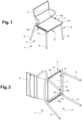
figure 1 est une vue en perspective d'un siège selon l'invention, - la
figure 2 est une vue en perspective de dessous du siège selon l'invention représenté enfigure 1 , - la
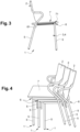
figure 3 est une vue de côté du siège illustré enfigure 1 , - la
figure 4 est une vue en perspective d'un empilement de sièges selon l'invention, - la
figure 5 est une vue en perspective selon un premier point de vue de l'organe guide du dispositif de mise en tension selon l'invention, - la
figure 6 est une vue en perspective selon un deuxième point de vue de l'organe guide du dispositif de mise en tension selon l'invention, - la
figure 7 est une vue en perspective de dessous de l'organe guide du dispositif de mise en tension selon l'invention, - la
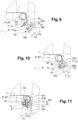
figure 8 est une vue en coupe transversale selon l'axe A-A représenté enfigure 7 , - la
figure 9 est une vue en coupe de détail d'une première étape de montage du dispositif de mise en tension selon l'invention, - la
figure 10 est une vue en coupe de détail d'une deuxième étape de montage du dispositif de mise en tension selon l'invention, - la
figure 10 est une vue en coupe de détail d'une troisième étape de montage du dispositif de mise en tension selon l'invention.
- there
figure 1 is a perspective view of a seat according to the invention, - there
figure 2 is a perspective view from below of the seat according to the invention shown infigure 1 , - there
Figure 3 is a side view of the seat shown infigure 1 , - there
Figure 4 is a perspective view of a stack of seats according to the invention, - there
Figure 5 is a perspective view from a first point of view of the guide member of the tensioning device according to the invention, - there
Figure 6 is a perspective view from a second point of view of the guide member of the tensioning device according to the invention, - there
figure 7 is a perspective view from below of the guide member of the tensioning device according to the invention, - there
figure 8 is a cross-sectional view along axis AA shown infigure 7 , - there
Figure 9 is a detailed sectional view of a first step of mounting the tensioning device according to the invention, - there
Figure 10 is a detailed sectional view of a second step of mounting the tensioning device according to the invention, - there
Figure 10 is a detailed sectional view of a third assembly step of the tensioning device according to the invention.
Le siège 1 selon l'invention est illustré aux
L'assise 7 est en matériau étirable et conformée pour couvrir au moins partiellement l'espace d'assise 63 délimité par les traverses 61, 62 du cadre d'assise 6. Par exemple, l'assise 7 est une toile qui peut être en matière synthétique, naturelle, ou un mélange des deux.The
Comme on peut le voir notamment en
Le siège 1 selon l'invention comprend en outre deux dispositifs de mise en tension 8 identiques et positionnés chacun respectivement de la première traverse 61 ou de la deuxième traverse 62 du cadre d'assise 6, comme visible en
Chaque dispositif de mise en tension 8 comprend un organe de rigidification 81 agencé sur un bord 71, 72 de l'assise 7. Plus particulièrement, l'extrémité de chaque bord 71, 72 de l'assise 7 est repliée de sorte à former une coulisse 73 dans laquelle est inséré l'organe de rigidification 81. L'organe de rigidification 81 est préférentiellement un jonc mais peut se présenter sous toute autre forme apte à être insérée dans la coulisse 73 ou apte à être solidarisée avec l'extrémité du bord 71, 72 de l'assise 7. Avantageusement, l'organe de rigidification 81 s'étendant au moins partiellement et préférentiellement tout le long du bord 71, 72. L'organe de rigidification 81 du dispositif de mise en tension peut être visualisé aux
Le dispositif de mise en tension 8 comprend en outre un organe guide 82 allongé configuré pour coopérer avec l'organe de rigidification 81. L'organe guide 82 est illustré en détail aux
Dans l'exemple illustré aux
Le logement 83 de l'organe guide 82 comprend une première partie de logement P1 du logement 83 de l'organe guide 82 est conformée pour coopérer avec l'organe de rigidification 81 et un bord 71, 72 de l'assise 7 et une deuxième de logement P2 du logement 83 de l'organe guide 82 est conformée pour coopérer avec la traverse 61, 62, et particulièrement avec une portion inférieure de la traverse 61, 62, comme illustré en
Dans l'exemple illustré en
En outre, comme illustré en
Selon l'invention, l'organe guide 82 est également configuré pour guider l'insertion des vis de fixation 50 dans la traverse 61, 62 et ainsi assurer la fixation de l'assise 7 sur le cadre d'assise 6 et le maintien de la mise en tension de l'assise 7.According to the invention, the
A cet effet, l'organe guide comprend au moins un ergot d'indexage 85, et plus préférentiellement une pluralité d'ergots d'indexage 85, comme illustré notamment en
Selon l'invention, chaque bord 71, 72 de l'assise 7 comprend au moins un trou de passage 74 dans lequel passe un ergot d'indexage 85, comme illustré en
Par ailleurs, l'organe guide 82 est également configuré pour permettre un empilement stable et simple de sièges selon l'invention.Furthermore, the
A cet effet, l'organe guide 82 comprend une portion 86 opposée au logement 83, comportant une première face 86a sensiblement plane et une deuxième face 86b agencée angulairement par rapport à la première face 86a, un congé angulaire étant formé à l'intersection de la première face 86a et la deuxième face 86b. Avantageusement, cette portion 86 permet l'empilement d'un siège 1 selon l'invention sur un autre comme illustré en
Selon l'invention, l'organe guide 82 comprend une pluralité d'orifices de fixation 87 à travers lesquels les vis de fixation 9 passent afin de solidariser l'organe guide 82 à une traverse 61, 62. Ces orifices de fixation 87 sont destinés à être positionnés en regard des perçages 63 ménages sur les traverses 61, 62.According to the invention, the
Selon l'invention, chaque organe de guidage 82 comprend en outre une extrémité 88 en forme de crochet permettant une accroche sur un montant du dossier 2 ou sur un piètement 3, 4 au niveau du cadre d'assise 6, comme illustré aux
Par ailleurs, il est possible d'utiliser un outil de montage (non visible) qui coopère avec des cavités 90 ménagés sur l'organe guide 82 sur la portion opposée au logement 83 et préférentiellement sur la deuxième face 86b.Furthermore, it is possible to use a mounting tool (not visible) which cooperates with
Le montage du dispositif de mise en tension 8 de l'assise 6 va maintenant être décrit en référence aux
Dans une première étape illustrée en
Dans une seconde étape illustrée en
Dans une étape intermédiaire, l'organe guide 82 va être déplacé dans un mouvement de rotation notamment grâce à l'appui de la paroi 83a du logement 83 sur la traverse 61 de sorte qu'à mesure que l'ergot d'indexage 85 pénètre le perçage 63 de la première traverse 61, le matériau de l'assise 7 s'étire et se tend progressivement.In an intermediate step, the
Dans une troisième étape illustrée en
En variante non représentée, la vis 9 peut être agencée dans l'organe guide 82 dès la première étape de montage.As a variant not shown, the screw 9 can be arranged in the
L'assise est avantageusement démontable en desserrant les vis et en retirant l'organe guide 82.The seat can advantageously be dismantled by loosening the screws and removing the
Bien entendu, l'invention n'est pas limitée au mode de réalisation décrit et représenté aux figures annexées. Des modifications restent possibles dans le cadre des revendications ci-jointes, notamment du point de vue de la constitution des divers éléments ou par substitution d'équivalents techniques, sans sortir pour autant du domaine de protection de l'invention.Of course, the invention is not limited to the embodiment described and represented in the appended figures. Modifications remain possible within the framework of the attached claims, in particular from the point of view of the constitution of the various elements or by substitution of technical equivalents, without departing from the scope of protection of the invention.
Claims (6)
- A seat (1) comprising:- a seat frame (6) comprising at least a first crosspiece (61) and a second crosspiece (62) positioned at a distance from the other and delimiting a seat space (63),- a seat (7) made of stretchable material and shaped to at least partially cover the seat space (63) delimited by the crosspieces (61, 62) of the seat frame (6), the seat (7) comprising at least a first edge (71) and a second opposite edge (72), the first edge (71) being positioned on the first crosspiece (61) of the seat frame (6) and the second edge (72) being positioned on the second crosspiece (62) of the seat frame (6),the seat (1) comprising at least one tensioning device comprising:- at least one stiffening member (81) arranged on the first edge (71), the stiffening member (81) extending at least partially along the first edge (71),- at least one guide member (82) fixed to the first crosspiece (61) of the seat frame (6) by fixing screws (9) received in bores (63) provided on the first crosspiece (61), the guide member (82) being elongated and being configured to cooperate with the stiffening member (81), the guide member (82) comprising a longitudinal housing (83) shaped to at least partially house the stiffening member (81), the first edge (71) of the seat (7) and at least a portion of the first crosspiece (61) of the seat frame (6), the housing (83) being arranged in an upper portion of the guide member (82) relative to the direction of mounting of the guide member (82) on the first crosspiece (61), the guide member (82) being configured to press and block the first edge (71) of the seat (7) and the stiffening member (81) against the first crosspiece (61),the guide member (82) comprises a plurality of indexing lugs (85) distributed over the length of the guide member (82), each indexing lug (85) being projecting and extending in a direction substantially perpendicular to the longitudinal direction in which the guide member (82) extends, each indexing lug (85) being configured to be positioned opposite and to be inserted into a respective through hole (74) provided on the first edge (71) of the seat (7) and in a respective bore (63) provided on the first crosspiece (61).
- The seat according to claim 1, wherein the first edge (71) of the seat (7) comprises a slide (73) formed by a fold of the end of the edge (71) of the seat (7), the slide (73) being shaped to house the stiffening member (81) within it.
- The seat according to any one of claims 1 or 2, wherein the seat (7) is made of a stretchable material, for example a canvas which can be made of synthetic or natural material, or a mixture of the two.
- The seat according to any one of claims 1 to 3, wherein a first housing part (P1) of the housing of the guide member (82) is shaped to cooperate with the stiffening member (81) and the first edge (71) of the seat and a second housing part (P2) of the housing of the guide member (82) is shaped to cooperate with the first crosspiece (61), and particularly with a lower portion of the first crosspiece (61).
- The seat according to any one of claims 1 to 4, wherein the guide member comprises a portion (86a, 86b) opposite to the housing, including a first face (86a) and a second face (86b) arranged angularly relative to the first face (86a), an angular fillet being formed at the intersection of the first face (86a) and the second face (86b), said portion opposite the housing being configured to receive a crosspiece portion (61) of another seat (1).
- The seat according to any one of claims 1 to 5, wherein the seat is equipped with a second tensioning device according to the invention arranged at the second crosspiece (62) of the seat frame (6).
Applications Claiming Priority (1)
| Application Number | Priority Date | Filing Date | Title |
|---|---|---|---|
| FR1860261A FR3088184B1 (en) | 2018-11-08 | 2018-11-08 | SEAT WITH SEAT TENSIONING DEVICE |
Publications (3)
| Publication Number | Publication Date |
|---|---|
| EP3649894A1 EP3649894A1 (en) | 2020-05-13 |
| EP3649894C0 EP3649894C0 (en) | 2024-07-10 |
| EP3649894B1 true EP3649894B1 (en) | 2024-07-10 |
Family
ID=65685681
Family Applications (1)
| Application Number | Title | Priority Date | Filing Date |
|---|---|---|---|
| EP19207187.6A Active EP3649894B1 (en) | 2018-11-08 | 2019-11-05 | Seat with device for tensioning a seat |
Country Status (3)
| Country | Link |
|---|---|
| EP (1) | EP3649894B1 (en) |
| ES (1) | ES2988833T3 (en) |
| FR (1) | FR3088184B1 (en) |
Citations (2)
| Publication number | Priority date | Publication date | Assignee | Title |
|---|---|---|---|---|
| WO2001022849A1 (en) * | 1999-09-29 | 2001-04-05 | Peter George Gordon Gregory | Chair |
| KR20090008035A (en) * | 2007-07-16 | 2009-01-21 | 듀오백코리아 주식회사 | Mesh cushion assembly of chair and assembly method thereof |
Family Cites Families (3)
| Publication number | Priority date | Publication date | Assignee | Title |
|---|---|---|---|---|
| JPS5140882Y2 (en) * | 1973-03-10 | 1976-10-06 | ||
| US5338091A (en) * | 1991-11-07 | 1994-08-16 | Miller Elmo E | Welt lock furniture construction |
| US5716101A (en) * | 1996-07-12 | 1998-02-10 | Bjip, Inc. | Seat rail attachment device |
-
2018
- 2018-11-08 FR FR1860261A patent/FR3088184B1/en active Active
-
2019
- 2019-11-05 ES ES19207187T patent/ES2988833T3/en active Active
- 2019-11-05 EP EP19207187.6A patent/EP3649894B1/en active Active
Patent Citations (2)
| Publication number | Priority date | Publication date | Assignee | Title |
|---|---|---|---|---|
| WO2001022849A1 (en) * | 1999-09-29 | 2001-04-05 | Peter George Gordon Gregory | Chair |
| KR20090008035A (en) * | 2007-07-16 | 2009-01-21 | 듀오백코리아 주식회사 | Mesh cushion assembly of chair and assembly method thereof |
Also Published As
| Publication number | Publication date |
|---|---|
| FR3088184A1 (en) | 2020-05-15 |
| EP3649894A1 (en) | 2020-05-13 |
| FR3088184B1 (en) | 2021-04-23 |
| EP3649894C0 (en) | 2024-07-10 |
| ES2988833T3 (en) | 2024-11-21 |
Similar Documents
| Publication | Publication Date | Title |
|---|---|---|
| EP0296075B1 (en) | Chair which can be dismantled | |
| EP2360322B1 (en) | Modular partition system with panels of stretched fabric | |
| FR2768034A3 (en) | BED TRANSFORMABLE | |
| WO2005005164A2 (en) | Device for tensioning and maintaining a canvas | |
| EP3649894B1 (en) | Seat with device for tensioning a seat | |
| WO2005016066A1 (en) | Backpack comprising an angular pivoting abdominal strap | |
| LU83132A1 (en) | SUPPORT ARM FOR SEAT OR ARMCHAIR COMPRISING A LIFT ARMREST | |
| FR2862579A1 (en) | SEAT FOR MOTOR VEHICLE SEAT WITH ADJUSTABLE LENGTH | |
| EP2028974B1 (en) | Collapsible rest support | |
| EP1516567B1 (en) | Retractable mezzanine bed | |
| WO2012076814A1 (en) | Retractable cover for the boot of a motor vehicle | |
| FR2959177A1 (en) | DEVICE FOR FIXING A SEAT, SUITABLE FOR CONTROLLING THE VOLUME OF THE STORAGE SPACE UNDER THIS HEADQUARTER | |
| FR3006865A1 (en) | PARASOL WITH SIDE DEPLOYMENT. | |
| EP0444106B1 (en) | System of armrests for toilets | |
| FR3055532B1 (en) | CONVERTIBLE EXTERIOR FURNITURE IN TRANSAT OR HAMMOCK | |
| FR2880640A1 (en) | Wall covering device for fixing e.g. shelf, has panels, each including anchorage unit for anchoring fixing unit of support device, and fixing screws in anchoring units fix two adjacent panels together | |
| FR3033689A1 (en) | ROLLER SUPPORT DEVICE ADAPTABLE TO THE FRONT PANEL OF ROLLING SHUTTER BOXES. | |
| WO2004033783A2 (en) | Support device for fabric items such as curtains | |
| FR2681025A1 (en) | WIPER BLADE COMPRISING LONGITUDINAL STOPPING MEANS OF THE WIPER BLADE. | |
| FR2770983A1 (en) | SEAT WITH TRIM ELEMENTS | |
| EP2067658A1 (en) | Arrangement of a sleeping system for a vehicle with a removable bedspring frame | |
| FR2542180A1 (en) | Device for removably fastening a cushion on the backrest and/or the seat of a chair | |
| EP2658416B1 (en) | Customizable armchair | |
| FR2903352A3 (en) | Motor vehicle body, has rear seat with rear edge having anchoring hooks engaged in fixation bolts respectively, when edges are driven towards front edge of projected part for maintaining base in fixed position with respect to part | |
| FR2934004A1 (en) | APRON OF OCCULTATION DEVICE, IN PARTICULAR OF SHUTTER. |
Legal Events
| Date | Code | Title | Description |
|---|---|---|---|
| PUAI | Public reference made under article 153(3) epc to a published international application that has entered the european phase |
Free format text: ORIGINAL CODE: 0009012 |
|
| STAA | Information on the status of an ep patent application or granted ep patent |
Free format text: STATUS: THE APPLICATION HAS BEEN PUBLISHED |
|
| AK | Designated contracting states |
Kind code of ref document: A1 Designated state(s): AL AT BE BG CH CY CZ DE DK EE ES FI FR GB GR HR HU IE IS IT LI LT LU LV MC MK MT NL NO PL PT RO RS SE SI SK SM TR |
|
| AX | Request for extension of the european patent |
Extension state: BA ME |
|
| STAA | Information on the status of an ep patent application or granted ep patent |
Free format text: STATUS: REQUEST FOR EXAMINATION WAS MADE |
|
| 17P | Request for examination filed |
Effective date: 20201113 |
|
| RBV | Designated contracting states (corrected) |
Designated state(s): AL AT BE BG CH CY CZ DE DK EE ES FI FR GB GR HR HU IE IS IT LI LT LU LV MC MK MT NL NO PL PT RO RS SE SI SK SM TR |
|
| STAA | Information on the status of an ep patent application or granted ep patent |
Free format text: STATUS: EXAMINATION IS IN PROGRESS |
|
| 17Q | First examination report despatched |
Effective date: 20221024 |
|
| GRAP | Despatch of communication of intention to grant a patent |
Free format text: ORIGINAL CODE: EPIDOSNIGR1 |
|
| STAA | Information on the status of an ep patent application or granted ep patent |
Free format text: STATUS: GRANT OF PATENT IS INTENDED |
|
| INTG | Intention to grant announced |
Effective date: 20240207 |
|
| GRAS | Grant fee paid |
Free format text: ORIGINAL CODE: EPIDOSNIGR3 |
|
| GRAA | (expected) grant |
Free format text: ORIGINAL CODE: 0009210 |
|
| STAA | Information on the status of an ep patent application or granted ep patent |
Free format text: STATUS: THE PATENT HAS BEEN GRANTED |
|
| AK | Designated contracting states |
Kind code of ref document: B1 Designated state(s): AL AT BE BG CH CY CZ DE DK EE ES FI FR GB GR HR HU IE IS IT LI LT LU LV MC MK MT NL NO PL PT RO RS SE SI SK SM TR |
|
| REG | Reference to a national code |
Ref country code: CH Ref legal event code: EP |
|
| REG | Reference to a national code |
Ref country code: DE Ref legal event code: R096 Ref document number: 602019054901 Country of ref document: DE |
|
| U01 | Request for unitary effect filed |
Effective date: 20240801 |
|
| U07 | Unitary effect registered |
Designated state(s): AT BE BG DE DK EE FI FR IT LT LU LV MT NL PT SE SI Effective date: 20240819 |
|
| U20 | Renewal fee for the european patent with unitary effect paid |
Year of fee payment: 6 Effective date: 20240918 |
|
| REG | Reference to a national code |
Ref country code: ES Ref legal event code: FG2A Ref document number: 2988833 Country of ref document: ES Kind code of ref document: T3 Effective date: 20241121 |
|
| PG25 | Lapsed in a contracting state [announced via postgrant information from national office to epo] |
Ref country code: GR Free format text: LAPSE BECAUSE OF FAILURE TO SUBMIT A TRANSLATION OF THE DESCRIPTION OR TO PAY THE FEE WITHIN THE PRESCRIBED TIME-LIMIT Effective date: 20241011 Ref country code: PL Free format text: LAPSE BECAUSE OF FAILURE TO SUBMIT A TRANSLATION OF THE DESCRIPTION OR TO PAY THE FEE WITHIN THE PRESCRIBED TIME-LIMIT Effective date: 20240710 |
|
| PG25 | Lapsed in a contracting state [announced via postgrant information from national office to epo] |
Ref country code: IS Free format text: LAPSE BECAUSE OF FAILURE TO SUBMIT A TRANSLATION OF THE DESCRIPTION OR TO PAY THE FEE WITHIN THE PRESCRIBED TIME-LIMIT Effective date: 20241110 |
|
| PG25 | Lapsed in a contracting state [announced via postgrant information from national office to epo] |
Ref country code: HR Free format text: LAPSE BECAUSE OF FAILURE TO SUBMIT A TRANSLATION OF THE DESCRIPTION OR TO PAY THE FEE WITHIN THE PRESCRIBED TIME-LIMIT Effective date: 20240710 |
|
| PG25 | Lapsed in a contracting state [announced via postgrant information from national office to epo] |
Ref country code: RS Free format text: LAPSE BECAUSE OF FAILURE TO SUBMIT A TRANSLATION OF THE DESCRIPTION OR TO PAY THE FEE WITHIN THE PRESCRIBED TIME-LIMIT Effective date: 20241010 |
|
| PG25 | Lapsed in a contracting state [announced via postgrant information from national office to epo] |
Ref country code: RS Free format text: LAPSE BECAUSE OF FAILURE TO SUBMIT A TRANSLATION OF THE DESCRIPTION OR TO PAY THE FEE WITHIN THE PRESCRIBED TIME-LIMIT Effective date: 20241010 Ref country code: PL Free format text: LAPSE BECAUSE OF FAILURE TO SUBMIT A TRANSLATION OF THE DESCRIPTION OR TO PAY THE FEE WITHIN THE PRESCRIBED TIME-LIMIT Effective date: 20240710 Ref country code: IS Free format text: LAPSE BECAUSE OF FAILURE TO SUBMIT A TRANSLATION OF THE DESCRIPTION OR TO PAY THE FEE WITHIN THE PRESCRIBED TIME-LIMIT Effective date: 20241110 Ref country code: HR Free format text: LAPSE BECAUSE OF FAILURE TO SUBMIT A TRANSLATION OF THE DESCRIPTION OR TO PAY THE FEE WITHIN THE PRESCRIBED TIME-LIMIT Effective date: 20240710 Ref country code: GR Free format text: LAPSE BECAUSE OF FAILURE TO SUBMIT A TRANSLATION OF THE DESCRIPTION OR TO PAY THE FEE WITHIN THE PRESCRIBED TIME-LIMIT Effective date: 20241011 |
|
| PG25 | Lapsed in a contracting state [announced via postgrant information from national office to epo] |
Ref country code: SM Free format text: LAPSE BECAUSE OF FAILURE TO SUBMIT A TRANSLATION OF THE DESCRIPTION OR TO PAY THE FEE WITHIN THE PRESCRIBED TIME-LIMIT Effective date: 20240710 |
|
| PG25 | Lapsed in a contracting state [announced via postgrant information from national office to epo] |
Ref country code: CZ Free format text: LAPSE BECAUSE OF FAILURE TO SUBMIT A TRANSLATION OF THE DESCRIPTION OR TO PAY THE FEE WITHIN THE PRESCRIBED TIME-LIMIT Effective date: 20240710 |
|
| PG25 | Lapsed in a contracting state [announced via postgrant information from national office to epo] |
Ref country code: SK Free format text: LAPSE BECAUSE OF FAILURE TO SUBMIT A TRANSLATION OF THE DESCRIPTION OR TO PAY THE FEE WITHIN THE PRESCRIBED TIME-LIMIT Effective date: 20240710 |
|
| PLBE | No opposition filed within time limit |
Free format text: ORIGINAL CODE: 0009261 |
|
| STAA | Information on the status of an ep patent application or granted ep patent |
Free format text: STATUS: NO OPPOSITION FILED WITHIN TIME LIMIT |
|
| 26N | No opposition filed |
Effective date: 20250411 |
|
| PG25 | Lapsed in a contracting state [announced via postgrant information from national office to epo] |
Ref country code: MC Free format text: LAPSE BECAUSE OF FAILURE TO SUBMIT A TRANSLATION OF THE DESCRIPTION OR TO PAY THE FEE WITHIN THE PRESCRIBED TIME-LIMIT Effective date: 20240710 |
|
| PGFP | Annual fee paid to national office [announced via postgrant information from national office to epo] |
Ref country code: GB Payment date: 20250929 Year of fee payment: 7 |
|
| PG25 | Lapsed in a contracting state [announced via postgrant information from national office to epo] |
Ref country code: IE Free format text: LAPSE BECAUSE OF NON-PAYMENT OF DUE FEES Effective date: 20241105 |
|
| U20 | Renewal fee for the european patent with unitary effect paid |
Year of fee payment: 7 Effective date: 20250930 |
|
| PG25 | Lapsed in a contracting state [announced via postgrant information from national office to epo] |
Ref country code: RO Free format text: LAPSE BECAUSE OF FAILURE TO SUBMIT A TRANSLATION OF THE DESCRIPTION OR TO PAY THE FEE WITHIN THE PRESCRIBED TIME-LIMIT Effective date: 20240710 |
|
| REG | Reference to a national code |
Ref country code: CH Ref legal event code: U11 Free format text: ST27 STATUS EVENT CODE: U-0-0-U10-U11 (AS PROVIDED BY THE NATIONAL OFFICE) Effective date: 20251201 |
|
| PGFP | Annual fee paid to national office [announced via postgrant information from national office to epo] |
Ref country code: NO Payment date: 20251121 Year of fee payment: 7 |
|
| PGFP | Annual fee paid to national office [announced via postgrant information from national office to epo] |
Ref country code: CH Payment date: 20251201 Year of fee payment: 7 |
|
| PG25 | Lapsed in a contracting state [announced via postgrant information from national office to epo] |
Ref country code: HU Free format text: LAPSE BECAUSE OF FAILURE TO SUBMIT A TRANSLATION OF THE DESCRIPTION OR TO PAY THE FEE WITHIN THE PRESCRIBED TIME-LIMIT; INVALID AB INITIO Effective date: 20191105 |
|
| PG25 | Lapsed in a contracting state [announced via postgrant information from national office to epo] |
Ref country code: CY Free format text: LAPSE BECAUSE OF FAILURE TO SUBMIT A TRANSLATION OF THE DESCRIPTION OR TO PAY THE FEE WITHIN THE PRESCRIBED TIME-LIMIT; INVALID AB INITIO Effective date: 20191105 |
|
| PGFP | Annual fee paid to national office [announced via postgrant information from national office to epo] |
Ref country code: ES Payment date: 20260211 Year of fee payment: 7 |