EP3649894B1 - Sitz mit vorrichtung zum spannen der sitzfläche - Google Patents
Sitz mit vorrichtung zum spannen der sitzfläche Download PDFInfo
- Publication number
- EP3649894B1 EP3649894B1 EP19207187.6A EP19207187A EP3649894B1 EP 3649894 B1 EP3649894 B1 EP 3649894B1 EP 19207187 A EP19207187 A EP 19207187A EP 3649894 B1 EP3649894 B1 EP 3649894B1
- Authority
- EP
- European Patent Office
- Prior art keywords
- seat
- crosspiece
- guide member
- edge
- housing
- Prior art date
- Legal status (The legal status is an assumption and is not a legal conclusion. Google has not performed a legal analysis and makes no representation as to the accuracy of the status listed.)
- Active
Links
Images

Classifications
-
- A—HUMAN NECESSITIES
- A47—FURNITURE; DOMESTIC ARTICLES OR APPLIANCES; COFFEE MILLS; SPICE MILLS; SUCTION CLEANERS IN GENERAL
- A47C—CHAIRS; SOFAS; BEDS
- A47C3/00—Chairs characterised by structural features; Chairs or stools with rotatable or vertically-adjustable seats
- A47C3/04—Stackable chairs or nesting chairs
-
- A—HUMAN NECESSITIES
- A47—FURNITURE; DOMESTIC ARTICLES OR APPLIANCES; COFFEE MILLS; SPICE MILLS; SUCTION CLEANERS IN GENERAL
- A47C—CHAIRS; SOFAS; BEDS
- A47C5/00—Chairs of special materials
- A47C5/04—Metal chairs, e.g. tubular
- A47C5/06—Special adaptation of seat upholstery or fabric for attachment to tubular chairs
Definitions
- the present invention relates to the field of furniture and more particularly to the field of seats comprising a seat made of stretchable and stretched material.
- the present invention relates to seats intended for outdoor or indoor use.
- seat an object for domestic use for seating one or more people, comprising at least one seat.
- the seat may have in addition to a seat, a backrest, feet, armrests or a seat alone.
- a seat within the meaning of the invention can therefore be a chair, a sun lounger, deckchair, a sofa, a wing chair, an armchair, a sofa, a stool, a bench or even a pouf.
- the invention aims to remedy all or part of the aforementioned drawbacks by proposing a seat whose tensioning of the seat is simple, intuitive, rapid, reliable and makes it possible to maintain the integrity of the seat over the course of the time.
- the subject of the invention is a seat comprising the characteristics of claim 1.
- the edge of the seat maintains its integrity thanks to the stiffening member and its cooperation with the guide member which does not damage the material of the seat when it is pressed against the first crosspiece.
- the tensioning of the seat is carried out uniformly over the length of the first edge thanks to the elongated shape of the housing of the guide member.
- the first edge of the seat and preferably, at the first edge and the second edge of the seat, comprises a slide formed by a fold of the end of the edge of the seat, the slide being shaped to accommodate the stiffening member within it.
- the seat is made of a stretchable material, for example a canvas which can be made of synthetic material, natural material, or a mixture both.
- the seat can be made for example of polyester sheathed in polyvinyl chloride.
- the housing of the guide member is arranged in an upper portion of the guide member, relative to the direction of mounting of the guide member on the crosspiece of the seat frame.
- the housing comprises stiffening spacers arranged in the housing transversely with respect to a longitudinal direction in which the guide member extends.
- the spacers make it possible to stiffen the walls of the guide member.
- the spacers are shaped to match the shape of the stiffening member on one portion and on another adjacent portion to match the shape of a lower portion of the first crosspiece.
- a second housing part of the housing of the guide member is shaped to cooperate with the first crosspiece, and particularly with a lower portion of the first crosspiece.
- the guide member comprises at least one projecting indexing pin extending in a direction substantially perpendicular to the longitudinal direction in which the guide member extends.
- the indexing pin has a frustoconical shape, which allows easy and progressive insertion through the passage hole of the edge of the seat.
- the guide member comprises a plurality of indexing lugs distributed over the length of the guide member, which makes it possible to distribute the forces uniformly along the guide member and to guide correctly the positioning of all the fixing screws and to allow their insertion into the holes of the crosspiece almost simultaneously in order to gain speed of assembly.
- the indexing lugs are distributed regularly over the length of the guide member.
- the indexing lugs are distributed so as to each be positioned opposite a drilling provided on the crosspiece. The lugs thus inserted in the crosspiece allow mechanical retention of the guide member before it is secured by screwing.
- the indexing lugs are distributed over the length of the guide member in the housing and alternating with orifices intended for the passage of fixing screws.
- At least the first crosspiece, and preferably each crosspiece of the seat frame comprises at least one hole, and preferably a plurality of holes, shaped to receive at least one indexing pin or one screw fixation within it.
- each guide member further comprises a hook-shaped end allowing attachment to an upright of the backrest or to a base at the level of the seat frame.
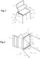
- Each tensioning device 8 comprises a stiffening member 81 arranged on an edge 71, 72 of the seat 7. More particularly, the end of each edge 71, 72 of the seat 7 is folded so as to form a slide 73 in which the stiffening member 81 is inserted.
- the stiffening member 81 is preferably a rod but can be in any other form capable of being inserted into the slide 73 or capable of being secured to the end of the edge 71, 72 of seat 7.
- the stiffening member 81 extending at least partially and preferably all along the edge 71, 72.
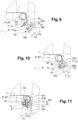
- the stiffening member 81 of the tensioning device can be visualized at figures 9 to 11 .
- the guide member 82 comprises pins 89 configured to grip the first edge 71 of the seat 7. These pins 89 are preferably positioned around the orifices 87.
- the guide member 82 is also configured to guide the insertion of the fixing screws 50 into the crosspiece 61, 62 and thus ensure the fixing of the seat 7 on the seat frame 6 and the maintenance of tensioning the seat 7.
- the guide member 82 comprises a plurality of fixing orifices 87 through which the fixing screws 9 pass in order to secure the guide member 82 to a crosspiece 61, 62.
- These fixing orifices 87 are intended to be positioned opposite the household holes 63 on the crosspieces 61, 62.
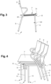
- each guide member 82 further comprises an end 88 in the form of a hook allowing attachment to an upright of the backrest 2 or to a base 3, 4 at the level of the seat frame 6, as illustrated in figures 5 to 7 .
- a mounting tool (not visible) which cooperates with cavities 90 provided on the guide member 82 on the portion opposite the housing 83 and preferably on the second face 86b.
- the assembly of the tensioning device 8 of the seat 6 will now be described with reference to the figures 9 to 11 .
- the assembly is described for a single tensioning device 8 on the first crosspiece 61 with the first edge 71 of the seat 7. It is obvious that this assembly is applicable to the second tensioning device 8 positioned on the second crosspiece 62.
- a third step illustrated in Figure 11 the body 92 of the fixing screw 9 is fully inserted into the crosspiece 61, the indexing pin 85 is partly retracted into the crosspiece 61, a lower portion of the crosspiece 61 is housed in the second housing portion P2 of the housing 83 of the guide member 82.
- the screw 9 can be arranged in the guide member 82 from the first assembly step.
Landscapes
- Seats For Vehicles (AREA)
- Connection Of Plates (AREA)
Claims (6)
- Sitz (1), der Folgendes umfasst:- einen Sitzrahmen (6), der mindestens einen ersten Querträger (61) und einen zweiten Querträger (62) umfasst, die im Abstand zueinander angeordnet sind und einen Sitzraum (63) begrenzen,- eine Sitzfläche (7) aus dehnbarem Material, die dazu ausgestaltet ist, mindestens teilweise den Sitzraum (63) abzudecken, der durch die Querträger (61, 62) des Sitzrahmens (6) begrenzt wird, wobei die Sitzfläche (7) mindestens eine erste Kante (71) und eine zweite gegenüberliegende Kante (72) umfasst, wobei die erste Kante (71) am ersten Querträger (61) des Sitzrahmens (6) positioniert ist und die zweite Kante (72) am zweiten Querträger (62) des Sitzrahmens (6) positioniert ist,wobei der Sitz (1) mindestens eine Spannvorrichtung umfasst, die Folgendes umfasst:- mindestens ein Versteifungselement (81), das an der ersten Kante (71) angeordnet ist, wobei sich das Versteifungselement (81) mindestens teilweise entlang der ersten Kante (71) erstreckt,- mindestens ein Führungselement (82), das am ersten Querträger (61) des Sitzrahmens (6) durch Befestigungsschrauben (9) befestigt ist, die in Bohrungen (63) aufgenommen sind, die am ersten Querträger (61) vorgesehen sind, wobei das Führungselement (82) langgestreckt und dazu konfiguriert ist, mit dem Versteifungselement (81) zusammenzuwirken, wobei das Führungselement (82) ein längliches Gehäuse (83) umfasst, das dazu ausgestaltet ist, das Versteifungselement (81), die erste Kante (71) der Sitzfläche (7) und mindestens einen Abschnitt des ersten Querträgers (61) des Sitzrahmens (6) mindestens teilweise aufzunehmen, wobei das Gehäuse (83) im Verhältnis zur Montagerichtung des Führungselements (82) am ersten Querträger (61) in einem oberen Abschnitt des Führungselements (82) angeordnet ist, wobei das Führungselement (82) dazu konfiguriert ist, die erste Kante (71) der Sitzfläche (7) und das Versteifungselement (81) gegen den ersten Querträger (61) zu drücken und zu blockieren,wobei das Führungselement (82) eine Vielzahl von Arretierzapfen (85) umfasst, die über die Länge des Führungselements (82) verteilt sind, wobei jeder Arretierzapfen (85) vorstehend ist und sich in eine Richtung erstreckt, die im Wesentlichen senkrecht zur Längsrichtung liegt, in der sich das Führungselement (82) erstreckt, wobei jeder Arretierzapfen (85) dazu konfiguriert ist, gegenüberliegend positioniert zu sein und in ein jeweiliges Durchtrittsloch (74), das an der ersten Kante (71) der Sitzfläche (7) vorgesehen ist, und in eine jeweilige Bohrung (63), die am ersten Querträger (61) ist, eingeführt zu werden.
- Sitz nach Anspruch 1, wobei die erste Kante (71) der Sitzfläche (7) eine Führungsschiene (73) aufweist, die durch eine Windung des Endes der Kante (71) der Sitzfläche (7) gebildet wird, wobei die Führungsschiene (73) dazu ausgestaltet ist, das Versteifungselement (81) in sich aufzunehmen.
- Sitz nach einem der Ansprüche 1 oder 2, wobei die Sitzfläche (7) aus einem dehnbaren Material, beispielsweise einem Gewebe, hergestellt wird, das aus synthetischem oder natürlichem Material oder einer Mischung aus beiden bestehen kann.
- Sitz nach einem der Ansprüche 1 bis 3, wobei ein erster Gehäuseteil (P1) des Gehäuses des Führungselements (82) dazu ausgestaltet ist, mit dem Versteifungselement (81) und der ersten Kante (71) der Sitzfläche zusammenzuwirken, und ein zweiter Gehäuseteil (P2) des Gehäuses des Führungselements (82) dazu ausgestaltet ist, mit dem ersten Querträger (61), und insbesondere mit einem unteren Abschnitt des ersten Querträgers (61), zusammenzuwirken.
- Sitz nach einem der Ansprüche 1 bis 4, wobei das Führungselement einen dem Gehäuse gegenüberliegenden Abschnitt (86a, 86b) umfasst, der eine erste Fläche (86a) und eine zweite Fläche (86b) aufweist, die im Verhältnis zur ersten Fläche (86a) winkelmäßig angeordnet sind, wobei eine eckige Ausrundung am Schnittpunkt der ersten Fläche (86a) und der zweiten Fläche (86b) gebildet wird, wobei der dem Gehäuse gegenüberliegende Abschnitt dazu konfiguriert ist, einen Abschnitt des Querträgers (61) eines anderen Sitzes (1) aufzunehmen.
- Sitz nach einem der Ansprüche 1 bis 5, wobei der Sitz mit einer zweiten Spannvorrichtung gemäß der Erfindung ausgestattet ist, die auf Höhe des zweiten Querträgers (62) des Sitzrahmens (6) angeordnet ist.
Applications Claiming Priority (1)
| Application Number | Priority Date | Filing Date | Title |
|---|---|---|---|
| FR1860261A FR3088184B1 (fr) | 2018-11-08 | 2018-11-08 | Siege avec dispositif de mise en tension d’assise |
Publications (3)
| Publication Number | Publication Date |
|---|---|
| EP3649894A1 EP3649894A1 (de) | 2020-05-13 |
| EP3649894C0 EP3649894C0 (de) | 2024-07-10 |
| EP3649894B1 true EP3649894B1 (de) | 2024-07-10 |
Family
ID=65685681
Family Applications (1)
| Application Number | Title | Priority Date | Filing Date |
|---|---|---|---|
| EP19207187.6A Active EP3649894B1 (de) | 2018-11-08 | 2019-11-05 | Sitz mit vorrichtung zum spannen der sitzfläche |
Country Status (3)
| Country | Link |
|---|---|
| EP (1) | EP3649894B1 (de) |
| ES (1) | ES2988833T3 (de) |
| FR (1) | FR3088184B1 (de) |
Citations (2)
| Publication number | Priority date | Publication date | Assignee | Title |
|---|---|---|---|---|
| WO2001022849A1 (en) * | 1999-09-29 | 2001-04-05 | Peter George Gordon Gregory | Chair |
| KR20090008035A (ko) * | 2007-07-16 | 2009-01-21 | 듀오백코리아 주식회사 | 의자의 메쉬형 쿠션 어셈블리 및 이의 조립 방법 |
Family Cites Families (3)
| Publication number | Priority date | Publication date | Assignee | Title |
|---|---|---|---|---|
| JPS5140882Y2 (de) * | 1973-03-10 | 1976-10-06 | ||
| US5338091A (en) * | 1991-11-07 | 1994-08-16 | Miller Elmo E | Welt lock furniture construction |
| US5716101A (en) * | 1996-07-12 | 1998-02-10 | Bjip, Inc. | Seat rail attachment device |
-
2018
- 2018-11-08 FR FR1860261A patent/FR3088184B1/fr active Active
-
2019
- 2019-11-05 ES ES19207187T patent/ES2988833T3/es active Active
- 2019-11-05 EP EP19207187.6A patent/EP3649894B1/de active Active
Patent Citations (2)
| Publication number | Priority date | Publication date | Assignee | Title |
|---|---|---|---|---|
| WO2001022849A1 (en) * | 1999-09-29 | 2001-04-05 | Peter George Gordon Gregory | Chair |
| KR20090008035A (ko) * | 2007-07-16 | 2009-01-21 | 듀오백코리아 주식회사 | 의자의 메쉬형 쿠션 어셈블리 및 이의 조립 방법 |
Also Published As
| Publication number | Publication date |
|---|---|
| FR3088184A1 (fr) | 2020-05-15 |
| EP3649894A1 (de) | 2020-05-13 |
| FR3088184B1 (fr) | 2021-04-23 |
| EP3649894C0 (de) | 2024-07-10 |
| ES2988833T3 (es) | 2024-11-21 |
Similar Documents
| Publication | Publication Date | Title |
|---|---|---|
| EP0296075B1 (de) | Zerlegbarer Stuhl | |
| EP2360322B1 (de) | Moduläres Trennwandsystem mit Paneelen aus gespanntem Tuch | |
| FR2768034A3 (fr) | Balancelle transformable en lit | |
| WO2005005164A2 (fr) | Dispositif apte a realiser la mise sous tension et le maintien d'une toile | |
| EP3649894B1 (de) | Sitz mit vorrichtung zum spannen der sitzfläche | |
| WO2005016066A1 (fr) | Sac a dos avec une sangle abdominale a pivotement angulaire | |
| LU83132A1 (fr) | Bras support pour siege ou fauteuil comportant un accoudoir relevable | |
| FR2862579A1 (fr) | Assise pour siege de vehicule automobile a longueur ajustable | |
| EP2028974B1 (de) | Zusammenklappbare stütze | |
| EP1516567B1 (de) | Ausziehbares Plattformbett | |
| WO2012076814A1 (fr) | Tendelet repliable pour coffre arriere pour vehicule automobile | |
| FR2959177A1 (fr) | Dispositif de fixation d'un siege, adapte au controle du volume de l'espace de rangement sous ledit siege | |
| FR3006865A1 (fr) | Parasol a deploiement lateral. | |
| EP0444106B1 (de) | Armlehnenanordnung für toiletten | |
| FR3055532B1 (fr) | Meuble d'exterieur convertible en transat ou en hamac | |
| FR2880640A1 (fr) | Dispositif de revetement de mur | |
| FR3033689A1 (fr) | Dispositif support de tringles, adaptable sur la face avant de caissons de volets roulants. | |
| WO2004033783A2 (fr) | Dispositif de maintien de pieces de tissus telles que des rideaux | |
| FR2681025A1 (fr) | Balai d'essuie-glace comportant des moyens d'arret longitudinal de la lame d'essuyage. | |
| FR2770983A1 (fr) | Siege a elements de garnissage | |
| EP2067658A1 (de) | Anordnung einer Schlafgelegenheit für Fahrzeug mit entfernbarem Bettrahmen | |
| FR2542180A1 (fr) | Dispositif pour fixer de facon amovible un coussin sur le dossier et/ou l'assise d'un siege | |
| EP2658416B1 (de) | Anpassbarer sessel | |
| FR2903352A3 (fr) | Fixation arriere pour caisse de vehicule automobile | |
| FR2934004A1 (fr) | Tablier de dispositif d'occultation, notamment de volet roulant. |
Legal Events
| Date | Code | Title | Description |
|---|---|---|---|
| PUAI | Public reference made under article 153(3) epc to a published international application that has entered the european phase |
Free format text: ORIGINAL CODE: 0009012 |
|
| STAA | Information on the status of an ep patent application or granted ep patent |
Free format text: STATUS: THE APPLICATION HAS BEEN PUBLISHED |
|
| AK | Designated contracting states |
Kind code of ref document: A1 Designated state(s): AL AT BE BG CH CY CZ DE DK EE ES FI FR GB GR HR HU IE IS IT LI LT LU LV MC MK MT NL NO PL PT RO RS SE SI SK SM TR |
|
| AX | Request for extension of the european patent |
Extension state: BA ME |
|
| STAA | Information on the status of an ep patent application or granted ep patent |
Free format text: STATUS: REQUEST FOR EXAMINATION WAS MADE |
|
| 17P | Request for examination filed |
Effective date: 20201113 |
|
| RBV | Designated contracting states (corrected) |
Designated state(s): AL AT BE BG CH CY CZ DE DK EE ES FI FR GB GR HR HU IE IS IT LI LT LU LV MC MK MT NL NO PL PT RO RS SE SI SK SM TR |
|
| STAA | Information on the status of an ep patent application or granted ep patent |
Free format text: STATUS: EXAMINATION IS IN PROGRESS |
|
| 17Q | First examination report despatched |
Effective date: 20221024 |
|
| GRAP | Despatch of communication of intention to grant a patent |
Free format text: ORIGINAL CODE: EPIDOSNIGR1 |
|
| STAA | Information on the status of an ep patent application or granted ep patent |
Free format text: STATUS: GRANT OF PATENT IS INTENDED |
|
| INTG | Intention to grant announced |
Effective date: 20240207 |
|
| GRAS | Grant fee paid |
Free format text: ORIGINAL CODE: EPIDOSNIGR3 |
|
| GRAA | (expected) grant |
Free format text: ORIGINAL CODE: 0009210 |
|
| STAA | Information on the status of an ep patent application or granted ep patent |
Free format text: STATUS: THE PATENT HAS BEEN GRANTED |
|
| AK | Designated contracting states |
Kind code of ref document: B1 Designated state(s): AL AT BE BG CH CY CZ DE DK EE ES FI FR GB GR HR HU IE IS IT LI LT LU LV MC MK MT NL NO PL PT RO RS SE SI SK SM TR |
|
| REG | Reference to a national code |
Ref country code: CH Ref legal event code: EP |
|
| REG | Reference to a national code |
Ref country code: DE Ref legal event code: R096 Ref document number: 602019054901 Country of ref document: DE |
|
| U01 | Request for unitary effect filed |
Effective date: 20240801 |
|
| U07 | Unitary effect registered |
Designated state(s): AT BE BG DE DK EE FI FR IT LT LU LV MT NL PT SE SI Effective date: 20240819 |
|
| U20 | Renewal fee for the european patent with unitary effect paid |
Year of fee payment: 6 Effective date: 20240918 |
|
| REG | Reference to a national code |
Ref country code: ES Ref legal event code: FG2A Ref document number: 2988833 Country of ref document: ES Kind code of ref document: T3 Effective date: 20241121 |
|
| PG25 | Lapsed in a contracting state [announced via postgrant information from national office to epo] |
Ref country code: GR Free format text: LAPSE BECAUSE OF FAILURE TO SUBMIT A TRANSLATION OF THE DESCRIPTION OR TO PAY THE FEE WITHIN THE PRESCRIBED TIME-LIMIT Effective date: 20241011 Ref country code: PL Free format text: LAPSE BECAUSE OF FAILURE TO SUBMIT A TRANSLATION OF THE DESCRIPTION OR TO PAY THE FEE WITHIN THE PRESCRIBED TIME-LIMIT Effective date: 20240710 |
|
| PG25 | Lapsed in a contracting state [announced via postgrant information from national office to epo] |
Ref country code: IS Free format text: LAPSE BECAUSE OF FAILURE TO SUBMIT A TRANSLATION OF THE DESCRIPTION OR TO PAY THE FEE WITHIN THE PRESCRIBED TIME-LIMIT Effective date: 20241110 |
|
| PG25 | Lapsed in a contracting state [announced via postgrant information from national office to epo] |
Ref country code: HR Free format text: LAPSE BECAUSE OF FAILURE TO SUBMIT A TRANSLATION OF THE DESCRIPTION OR TO PAY THE FEE WITHIN THE PRESCRIBED TIME-LIMIT Effective date: 20240710 |
|
| PG25 | Lapsed in a contracting state [announced via postgrant information from national office to epo] |
Ref country code: RS Free format text: LAPSE BECAUSE OF FAILURE TO SUBMIT A TRANSLATION OF THE DESCRIPTION OR TO PAY THE FEE WITHIN THE PRESCRIBED TIME-LIMIT Effective date: 20241010 |
|
| PG25 | Lapsed in a contracting state [announced via postgrant information from national office to epo] |
Ref country code: RS Free format text: LAPSE BECAUSE OF FAILURE TO SUBMIT A TRANSLATION OF THE DESCRIPTION OR TO PAY THE FEE WITHIN THE PRESCRIBED TIME-LIMIT Effective date: 20241010 Ref country code: PL Free format text: LAPSE BECAUSE OF FAILURE TO SUBMIT A TRANSLATION OF THE DESCRIPTION OR TO PAY THE FEE WITHIN THE PRESCRIBED TIME-LIMIT Effective date: 20240710 Ref country code: IS Free format text: LAPSE BECAUSE OF FAILURE TO SUBMIT A TRANSLATION OF THE DESCRIPTION OR TO PAY THE FEE WITHIN THE PRESCRIBED TIME-LIMIT Effective date: 20241110 Ref country code: HR Free format text: LAPSE BECAUSE OF FAILURE TO SUBMIT A TRANSLATION OF THE DESCRIPTION OR TO PAY THE FEE WITHIN THE PRESCRIBED TIME-LIMIT Effective date: 20240710 Ref country code: GR Free format text: LAPSE BECAUSE OF FAILURE TO SUBMIT A TRANSLATION OF THE DESCRIPTION OR TO PAY THE FEE WITHIN THE PRESCRIBED TIME-LIMIT Effective date: 20241011 |
|
| PG25 | Lapsed in a contracting state [announced via postgrant information from national office to epo] |
Ref country code: SM Free format text: LAPSE BECAUSE OF FAILURE TO SUBMIT A TRANSLATION OF THE DESCRIPTION OR TO PAY THE FEE WITHIN THE PRESCRIBED TIME-LIMIT Effective date: 20240710 |
|
| PG25 | Lapsed in a contracting state [announced via postgrant information from national office to epo] |
Ref country code: CZ Free format text: LAPSE BECAUSE OF FAILURE TO SUBMIT A TRANSLATION OF THE DESCRIPTION OR TO PAY THE FEE WITHIN THE PRESCRIBED TIME-LIMIT Effective date: 20240710 |
|
| PG25 | Lapsed in a contracting state [announced via postgrant information from national office to epo] |
Ref country code: SK Free format text: LAPSE BECAUSE OF FAILURE TO SUBMIT A TRANSLATION OF THE DESCRIPTION OR TO PAY THE FEE WITHIN THE PRESCRIBED TIME-LIMIT Effective date: 20240710 |
|
| PLBE | No opposition filed within time limit |
Free format text: ORIGINAL CODE: 0009261 |
|
| STAA | Information on the status of an ep patent application or granted ep patent |
Free format text: STATUS: NO OPPOSITION FILED WITHIN TIME LIMIT |
|
| 26N | No opposition filed |
Effective date: 20250411 |
|
| PG25 | Lapsed in a contracting state [announced via postgrant information from national office to epo] |
Ref country code: MC Free format text: LAPSE BECAUSE OF FAILURE TO SUBMIT A TRANSLATION OF THE DESCRIPTION OR TO PAY THE FEE WITHIN THE PRESCRIBED TIME-LIMIT Effective date: 20240710 |
|
| PGFP | Annual fee paid to national office [announced via postgrant information from national office to epo] |
Ref country code: GB Payment date: 20250929 Year of fee payment: 7 |
|
| PG25 | Lapsed in a contracting state [announced via postgrant information from national office to epo] |
Ref country code: IE Free format text: LAPSE BECAUSE OF NON-PAYMENT OF DUE FEES Effective date: 20241105 |
|
| U20 | Renewal fee for the european patent with unitary effect paid |
Year of fee payment: 7 Effective date: 20250930 |
|
| PG25 | Lapsed in a contracting state [announced via postgrant information from national office to epo] |
Ref country code: RO Free format text: LAPSE BECAUSE OF FAILURE TO SUBMIT A TRANSLATION OF THE DESCRIPTION OR TO PAY THE FEE WITHIN THE PRESCRIBED TIME-LIMIT Effective date: 20240710 |
|
| REG | Reference to a national code |
Ref country code: CH Ref legal event code: U11 Free format text: ST27 STATUS EVENT CODE: U-0-0-U10-U11 (AS PROVIDED BY THE NATIONAL OFFICE) Effective date: 20251201 |
|
| PGFP | Annual fee paid to national office [announced via postgrant information from national office to epo] |
Ref country code: NO Payment date: 20251121 Year of fee payment: 7 |
|
| PGFP | Annual fee paid to national office [announced via postgrant information from national office to epo] |
Ref country code: CH Payment date: 20251201 Year of fee payment: 7 |
|
| PG25 | Lapsed in a contracting state [announced via postgrant information from national office to epo] |
Ref country code: HU Free format text: LAPSE BECAUSE OF FAILURE TO SUBMIT A TRANSLATION OF THE DESCRIPTION OR TO PAY THE FEE WITHIN THE PRESCRIBED TIME-LIMIT; INVALID AB INITIO Effective date: 20191105 |
|
| PG25 | Lapsed in a contracting state [announced via postgrant information from national office to epo] |
Ref country code: CY Free format text: LAPSE BECAUSE OF FAILURE TO SUBMIT A TRANSLATION OF THE DESCRIPTION OR TO PAY THE FEE WITHIN THE PRESCRIBED TIME-LIMIT; INVALID AB INITIO Effective date: 20191105 |
|
| PGFP | Annual fee paid to national office [announced via postgrant information from national office to epo] |
Ref country code: ES Payment date: 20260211 Year of fee payment: 7 |