EP3649726B1 - Actionneur vibrotactile - Google Patents
Actionneur vibrotactile Download PDFInfo
- Publication number
- EP3649726B1 EP3649726B1 EP18734256.3A EP18734256A EP3649726B1 EP 3649726 B1 EP3649726 B1 EP 3649726B1 EP 18734256 A EP18734256 A EP 18734256A EP 3649726 B1 EP3649726 B1 EP 3649726B1
- Authority
- EP
- European Patent Office
- Prior art keywords
- network
- electromagnetic coils
- flat electromagnetic
- permanent
- magnets
- Prior art date
- Legal status (The legal status is an assumption and is not a legal conclusion. Google has not performed a legal analysis and makes no representation as to the accuracy of the status listed.)
- Active
Links
Images

Classifications
-
- H—ELECTRICITY
- H02—GENERATION; CONVERSION OR DISTRIBUTION OF ELECTRIC POWER
- H02K—DYNAMO-ELECTRIC MACHINES
- H02K33/00—Motors with reciprocating, oscillating or vibrating magnet, armature or coil system
- H02K33/02—Motors with reciprocating, oscillating or vibrating magnet, armature or coil system with armatures moved one way by energisation of a single coil system and returned by mechanical force, e.g. by springs
- H02K33/04—Motors with reciprocating, oscillating or vibrating magnet, armature or coil system with armatures moved one way by energisation of a single coil system and returned by mechanical force, e.g. by springs wherein the frequency of operation is determined by the frequency of uninterrupted AC energisation
-
- H—ELECTRICITY
- H02—GENERATION; CONVERSION OR DISTRIBUTION OF ELECTRIC POWER
- H02K—DYNAMO-ELECTRIC MACHINES
- H02K33/00—Motors with reciprocating, oscillating or vibrating magnet, armature or coil system
- H02K33/16—Motors with reciprocating, oscillating or vibrating magnet, armature or coil system with polarised armatures moving in alternate directions by reversal or energisation of a single coil system
-
- G—PHYSICS
- G06—COMPUTING OR CALCULATING; COUNTING
- G06F—ELECTRIC DIGITAL DATA PROCESSING
- G06F3/00—Input arrangements for transferring data to be processed into a form capable of being handled by the computer; Output arrangements for transferring data from processing unit to output unit, e.g. interface arrangements
- G06F3/01—Input arrangements or combined input and output arrangements for interaction between user and computer
- G06F3/016—Input arrangements with force or tactile feedback as computer generated output to the user
-
- G—PHYSICS
- G08—SIGNALLING
- G08B—SIGNALLING SYSTEMS, e.g. PERSONAL CALLING SYSTEMS; ORDER TELEGRAPHS; ALARM SYSTEMS
- G08B6/00—Tactile signalling systems, e.g. tactile personal calling systems
-
- H—ELECTRICITY
- H04—ELECTRIC COMMUNICATION TECHNIQUE
- H04M—TELEPHONIC COMMUNICATION
- H04M19/00—Current supply arrangements for telephone systems
- H04M19/02—Current supply arrangements for telephone systems providing ringing current or supervisory tones, e.g. dialling tone or busy tone
- H04M19/04—Current supply arrangements for telephone systems providing ringing current or supervisory tones, e.g. dialling tone or busy tone the ringing-current being generated at the substations
- H04M19/047—Vibrating means for incoming calls
Definitions
- the present invention relates to a vibrotactile actuator making it possible to generate vibrations from movements generated by a Halbach network interacting with an electric current.
- the invention finds applications in the field of haptic interfaces intended to reproduce tactile sensations using vibrotactile stimuli and, generally speaking, in all areas where vibrations cause sensations such as, for example, in the field of simulators or in the field of augmented reality.
- vibrotactile actuators to communicate information by touch to a human being.
- These vibrotactile actuators transform an electrical signal, generated by a machine (for example a mobile phone or a computer), into a vibration signal perceptible by touch.
- the mobile telephone is a well-known example of a device equipped with a vibrotactile actuator.
- the vibrotactile actuator generally comprises an eccentric mass driven in rotation by an electric motor, this mass generating, through its movements, vibrations due to the principle of conservation of angular momentum which inform the user of information, for example example of receiving a telephone call or a message.
- FIG. 1 Another example of a known vibrotactile actuator is that used in certain touch pads making it possible to direct, by sliding a finger, a pointer on a screen.
- touch pads the movement of the pointer is obtained by variation of a weak electric current linked to the proximity of the fingers, which by nature have easily detectable dielectric properties.
- This electrical variation also makes it possible, through brief oscillations, to simulate the “click” of a mechanical button, such as a mouse button.
- Such touchpads have been described, in particular by MacKenzie, I. Scott, and Aleks Oniszczak in the article: "The tactile touchpad", In CHI'97 Extended Abstracts on Human Factors in Computing Systems, pp. 309-310, ACM, 1997 .
- these vibrotactile actuators are not only relatively thick but also they are generally single frequency. They therefore make it possible to generate vibrations of a vibratory amplitude irremediably linked to the speed of rotation and therefore to the frequency of oscillation, which offers a unique feeling to the user.
- Another family of vibrotactile actuators are based on the resonance phenomenon of a mass-spring system and therefore have the same drawback. In other words, the user feels vibrations, but all vibrations are perceived in the same way.
- These known vibrotactile actuators cannot therefore be used in haptic applications where we seek to reproduce the rich sensations of touch.
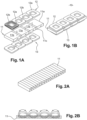
- Such a linear motor 10 comprises, as shown in the Figures 1A and 1B , a network of magnets 11 comprising a plurality of aligned magnets 11a, 11b whose polarities are alternating. This configuration of the network of magnets 11 allows a concentration of field lines, generated by said network, substantially orthogonal to the plane of the network of magnets 11.
- This linear motor 10 further comprises a first and a second sets 12, 13 electromagnetic coils, flat and rectangular.
- the sets of coils 12, 13 are each positioned in a plane parallel to the plane of the network of magnets 11, on either side of said network of magnets 11. In this way, the sets of coils 12, 13 create, under the effect of an electric current passing through them, a horizontal Laplace force, between each plane of the sets of coils and the plane of the network of magnets.
- This Laplace force has the effect of moving the sets of coils 12, 13 relative to the network of magnets 11 and, conversely, of moving the network of magnets relative to the sets of coils so as to generate a translation movement.
- One of the best-known applications of such a linear motor is the magnetic levitation train in which the relative displacements, the sets of coils and the network of magnets ensure the movement of the train along a rail.
- Another linear vibrator described in the document US 2012/104875 A1 , proposes an array of flat coils positioned parallel to an array of magnets.
- This linear vibrator has a radial magnetic structure which, due to its symmetry, causes leakage of magnetic fields on the exterior face, which requires the use of a mild steel frame which increases the thickness of the linear vibrator.
- Other radial magnetic structures are described in the documents US 2012/112565 A1 , Us 2016/226359 A1 And CN 105 680 663 A which all have the same disadvantages of leakage of magnetic fields and therefore the use of at least one mild steel element.
- certain magnet configurations have the particularity of guiding the field lines on only one side of the plane of the magnet network.
- This configuration of magnets called the Halbach network, consists of arranging the magnets so as to break the symmetry of the geometry of the path of the field lines, as shown on the Figures 2A and 2B .
- the magnets are arranged so that the polarization of adjacent magnets differs.
- the polarization of two contiguous magnets can be oriented in orthogonal directions or at angles less than 90°, as in the example of figures 2A-2B where the offset angles of the polarization directions are of the order of 45°. The smaller the angle between the polarization directions, the more the dispersion of the field lines is reduced, which allows, for the same current, a greater relative displacement in translation.
- a vibrotactile actuator comprising a linear motor with a Halbach network in which the translational movements generated by the linear motor are transformed into haptic vibrations by sliding or elastic guide means.
- the vibrotactile actuator as defined in the claims has the advantage of having a wide bandwidth allowing the generation of a large range amplitudes and frequencies of vibrations that can reproduce the sensations of touch in humans.
- This actuator also has the advantage of having a small thickness allowing it to be introduced into all kinds of devices.
- the positioning of the different elements of the actuator according to the invention will be defined in an orthogonal reference frame XYZ, in which the X axis defines the longitudinal direction of the actuator, the Y axis defines its direction transversal and the Z axis defines its vertical direction.
- the planes PA of the network of magnets and PB of the network of coils are parallel planes, defined according to the plane XY of the coordinate system XYZ.
- a vibrotactile actuator comprising a linear motor with a Halbach network in which the translational movements generated by the linear motor are transformed into haptic vibrations, is described in detail below, with reference to the accompanying drawings.
- This example illustrates the characteristics and advantages of the invention. However, it is recalled that the invention is not limited to this example.
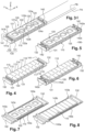
- FIG. 3A represents a vibrotactile actuator according to certain embodiments of the invention.
- This vibrotactile actuator 100 comprises a network of coils 120 and a network of magnets 110 together forming a linear motor.
- the coil array 120 includes a plurality of electromagnetic coils juxtaposed longitudinally next to each other.
- the network of coils comprises four coils, referenced 121, 122, 123, 124.
- the coils 121-124 electrically powered by a power source not visible in the figures, are connected together so as to form a linear network of coils. They are arranged so that the current flows, in the adjacent segments of two juxtaposed coils, in common directions which alternate from pair to pair.
- the coils are arranged so that the current flows in the same direction in the first segment, for example 121a, of a first coil 121 and in the second segment 122a of a second coil 122 when the first segment of the first coil is contiguous to the second segment of the second coil.
- the current in segment 121a of coil 121 and the current in segment 122a of coil 122 flow in the same first direction while the current in segment 122b of coil 122 and the current in segment 123b of coil 123 circulate in the same second direction, this second direction being opposite to the first direction.
- the current in segment 122a of coil 122 and the current in the segment 124a of coil 124 circulate in the same direction, for example the first direction.
- the coil array 120 comprises a plurality of electromagnetic coils not contiguous to each other.
- the network of coils 120 comprises coils positioned in the same plane but spaced from each other by a predefined distance.
- the network of coils 120 comprises two coils, referenced 121' and 123', spaced at a distance of the order of the width of a magnet of the network of magnets 110.
- the coils do not are not contiguous to each other and are crossed by a current whose direction is identical from one coil to the other.
- the number of coils can vary depending, for example, on the dimensions of the linear motor or the dimensions of the coils, without however modifying the configuration of the actuator described.
- the coils electrically powered by a power source not visible in the figures, are connected together so as to form a linear network of coils 120. They are arranged so that the current flows in identical directions in each of the coils. In other words, the coils are arranged so that the current flows in the opposite direction in the first segment, for example 121'a, of a first coil 121' and in the second segment 122'a of a second coil 122' when the first segment of the first coil is close to the second segment of the second coil.
- the coils 121-124 or 121'-124' are flat coils, for example of rectangular shape, positioned in the same first plane PB.
- the coils 121-124 can be mounted and fixed on a flat support 125 so as to ensure the flatness of the coil network 120.
- This support 125 can be a plate made of an insulating material providing a structural function such as ABS (Acrylonitrile Butadiene Styrene) or any other injectable plastic.
- the network of magnets 110 is a Halbach network, as shown in the figure 4 , comprising a plurality of flat permanent magnets whose polarities are oriented in more than two different directions.
- the polarity of a first magnet 118 can be oriented in the direction direction Y, that a third magnet 116 (adjacent to the second magnet) is oriented in the -X direction and that a fourth magnet 115 (adjacent to the third magnet) is oriented in a direction forming an angle of 90° with the direction -X and direction -Y.
- a Halbach network makes it possible to orient the magnetic field generated by the network of magnets on the same face of said network.
- the Halbach network 110 comprises nine permanent magnets 111-119, subsequently called simply magnets, which have four directions of different polarities.
- the number of magnets and the number of directions of the polarities can vary without however modifying the configuration of the actuator as described subsequently, the polarities of the magnets being able, for example, to be oriented in the Y or - Y directions and in all kinds of directions of the XY plane.
- the magnets 111-119 are arranged longitudinally one after the other and assembled with each other, for example by gluing, embedding or hooping. These magnets 111-119 are positioned so that two consecutive magnets have polarities of different orientations.
- the polarity of the magnet 111 is oriented in a direction at -90° relative to the X axis
- the polarity of the magnet 112 is oriented in the direction opposite to the X axis
- the polarity of the magnet 113 is oriented in a direction at 90° to the axis X
- the polarity of the magnet 114 is oriented in the direction of the axis
- the magnets of the network of magnets 110 are arranged linearly along a plane PA, parallel to the plane PB of the network of coils 120, as shown in the Figure 3A .
- the planes PA of the network of magnets and PB of the network of coils are parallel planes, defined along the axes X and Y of the coordinate system XYZ.
- the plane PA of the network of magnets 110 is distant, along the Z axis, from the plane PB of the network of coils 120 so as to generate an air gap e (along the Z axis) between the network of coils and the network of magnets.
- This air gap e is of a reduced size compared to the longitudinal and transverse dimensions of magnet and coil arrays.
- the array of coils 120 is positioned above the array of magnets 110, as shown in the Figure 3A .
- the vibrotactile actuator 100 comprises in an orderly manner the frame 130, the network of magnets 110 and the network of coils 120.
- the network of coils 120 is then directly above the network of magnets 110.
- the network of magnets 110 is positioned above the network of coils 120.
- the vibrotactile actuator 100 comprises in an orderly manner, the frame 130, the network of coils 120 and the network of magnets 110.
- the network of permanent magnets 110 is then directly above the network of coils 120.
- said network of magnets generates magnetic field lines directed towards the network of coil 120.
- an oscillating current circulates in the network of coils 120
- an oscillating Laplace force is generated along the axis linear generating relative translational movements between said network of magnets and said network of coils.
- the vibrotactile actuator comprises elastic guide means, referenced 140 on the figures 3 And 4 , adapted to ensure the longitudinal movement of the parts 110 and 120 relative to each other so that if one of them is linked to an external object any movement of the free part will result in a movement of the external object by the principle of conservation of angular momentum, transforming electrical energy into haptic vibrations.
- These elastic guide means 140 form an elastic suspension which guides one of the networks relative to the other along a substantially rectilinear trajectory.
- These elastic guide means 140 can be in the form, for example, of one or more guide and return elements, called more simply return elements, or a slide system - as described below - which aim to transform electrical energy by interaction of networks of coils 120 and magnets 110 into haptic vibrations using the force of Laplace for this purpose. Indeed, the elastic guide means 140, due to their elastic characteristic, offer a wide amplitude of vibration.
- the vibrotactile actuator comprises a frame 130 in which the network of coils 120 and the network of magnets 110 are housed at least in part.
- This frame 130 may include a longitudinal plate 131 equipped with at least one of its ends, a support arm 132.
- the plate 131 of the frame 130 includes a support arm 132 at each of its longitudinal ends.
- the elastic guide means 140 can be mounted in the frame 130 and secured with the support arms 132 and one or other of the networks of coils 120 or magnets 110.
- the network of magnets 110 is secured to the plate 131 of the frame 130 and the network of coils 120 is suspended above the network of magnets 110, via the guide means 140.
- An air gap e of fine thickness by relative to the other dimensions of the vibrotactile actuator, is then created between the network of magnets 110 and the network of coils 120.
- This air gap can be, for example, a few tens of micrometers.
- the network of coils 120 is free to move in translation in the direction ) relative to the network of magnets 110.
- the elastic guide means 140 may comprise return elements 140 provided between the network of coils 120 and the support arms 132, as shown in the figure. Figure 3A , or between the network of magnets 110 and the support arms 132, as shown in the Figure 4 .
- one of the networks (coils or magnets) is fixed on the plate 131 of the frame 130 while the other network is suspended between the return elements 140.
- the return elements 140 can be, for example, thin blades 141, 142 each positioned between the network of coils 120 or the network of magnets 110 and a support arm 132 of the frame 130.
- Each thin blade 141 can have, in the plane PA or the plane PB, an S shape with a first vertex 141a fixed on the support arm 132 and a second vertex 141b fixed at the longitudinal end of the network of coils or magnets. Examples of thin S 141 sections are shown on the figures 3 And 4 . Such thin S-shaped blades provide high torsional rigidity.
- the return elements 140 can be thin blades 142 having, in the plane PA or the plane PB, an X shape with two legs of the X 142a fixed on the support arm 132 and two other legs of the X 142b fixed to a longitudinal end of the network of coils or magnets.
- These embodiments have the advantage of producing substantially more precise guidance than that provided by the thin S-shaped blades 141.
- the thin blades 141, 142 can be made from elastomers such as polysiloxanes, from rubbers or metal strips with a high elastic limit such as certain copper alloys or steels making it possible to generate haptic vibrations from the linear mechanical energy produced. networks of coils and magnets.
- the thin blades can, in particular, be made from a copper beryllium alloy, this material having the advantage of being sufficiently flexible and elastic to offer a wide bandwidth of the order of 10 Hz to several kHz.
- the tops of the thin S-shaped blades 141 or the legs of the thin X-shaped blades 142 are fixed on the support arms 132 and/or the longitudinal ends of the network of coils or the network of magnets, by for example by gluing.
- the tops of the thin S-shaped blades 141 or the legs of the thin X-shaped blades 142 are molded, for example by injection, with the support arms 132 and/or the ends of the support 125 of the network of coils.
- the thin blades 141 or 142 are made of an electrically conductive material.
- the thin strips not only form the return elements of the actuator 100 but they also form the electrical connections which electrically connect the coils to an electrical power source.
- the network of magnets 110 has the advantage of forming a thermal bridge which promotes the dissipation of the heat produced by the Joule effect, in the coils 121-124 during the circulation of the electric current.
- the return elements 140 are slides 143a, 143b mounted sliding on slides 143c and forming, with said slides, a slide system 143. Examples of such embodiments are shown in the figures 7 and 8 .
- This slide system 143 comprises, for example, two parallel slides 143c, positioned longitudinally on either side of the network of coils 120 (example of the Figure 7 ) or the network of magnets 110 (example of the figure 8 ). These slides 143c are fixed, at each longitudinal end, in the support arms 132 of the frame 130.
- the slides 143a, 143b of the slide system 143 are designed to slide on the slides 143c.
- the slides 143a, 143b are mobile transverse elements, integral with the network of coils 120 (example of the Figure 7 ) or the network of magnets 110 (example of the figure 8 ). These slides 143a, 143b can each be fixed to a longitudinal end of the network of coils or magnets, for example by gluing, or can be formed in one piece, for example by molding, with the support 125 of the network of coils 120.
- the guidance can be provided by a rolling system where metal balls, plastic or elastomer, are constrained by raceways of a type well known to the skilled person.
- the slides 143a, 143b can be associated with compression springs, for example two, provided to recenter the slides towards a rest position.
- the slides 143a, 143b made from a pair of materials with a low coefficient of friction such as steel against sintered bronze, or steel against self-lubricating plastics, make it possible to precisely guide the movement of the moving parts resulting from the interaction of the networks of coils and magnets in haptic vibrations.
- the network of coils 120 and the network of magnets 110 are at least partially enclosed in a formwork 150, as in the example of the Figure 9 .
- This formwork 150 is fixed on the network of coils 120 (embodiment not shown) or on the network of magnets 110 (mode of embodiment of the Figure 9 ) so as to be mobile in translation relative to the plate 131 of the frame 130.
- the formwork 150 then moves linearly, simultaneously with the network (of coils or magnets) to which it is integral.
- the return elements 140 are provided between the formwork 150 and the support arms 132 of the frame 130, which allows simplified assembly of the return means 140 in the actuator 100.
- the network of coils 120 and the network of magnets 110 are positioned between the frame 130 and a movable surface 152.
- the movable surface 152 for example a flat surface such as a touch screen or a left surface, is fixed on the network d magnets 110, the network of coils 120 being fixed on the frame 130.
- the network of coils 120 and the network of magnets 110 are positioned opposite each other and spaced one from the other. other so as to allow the movement of the movable surface 152 relative to the frame 130.
- the movable surface 152 and the frame 130 are connected by elastic guide means 140, such as for example a flexible connection, which authorize the movement of said movable surface 152.
- All of the networks of coils 120 and magnets 110 thus generate haptic feedback in the movable surface 152.
- a single coil array 120 and a single magnet array 110 are positioned facing each other, substantially in the center of the movable surface 152.
- a first set of arrays of coils 120 and magnets 110 is positioned at one end of the movable surface 152, a second set of arrays of coils 120' and magnets 110' being positioned at another end of said movable surface .
- the number of sets of coil arrays and magnets and their positioning may depend on various criteria such as, for example, the dimensions and/or the mass of the moving surface, the dimensions of the networks of coils and magnets, the desired applications, etc.
- the moving mass is optimized in the vibrotactile actuator of the invention, which allows said actuator to have a dimension along the Z axis that is small compared to the dimensions along the X and Y axes.
- the vibrotactile actuator of the invention can thus have a thickness of less than 4mm, which gives it a format whose dimension ratio approaches that of a plate.
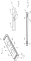
- the coils 121-124 of the network of coils 120 can be produced by means of conductive tracks etched in a multilayer printed circuit.
- An example of an actuator comprising such a network of coils is shown on the Figure 10A .
- the coil array is etched in the substrate 160 to the surface of which electronic components 161 used by the device for applications other than haptic vibrations are connected.
- the substrate 160 constitutes not only the network of coils but also the plate 131 of the frame. Support arms 132 are then fixed directly on the substrate 160 to maintain the network of magnets 110 above the etched coils.
- the actuator then has a thickness substantially equal to that of an electronic component.
- each coil 121-124 of the network of coils comprises an electric wire of round section wound, for example around a mandrel of rectangular section, so as to form a flat rectangular coil.
- each coil 121-124 of the coil array includes a wound conductive ribbon 170.
- This conductive ribbon 170 for example made of sufficiently pure copper or aluminum, is wound along its length, following a rectangular shape, so as to form a rectangular coil such as that shown on the Figure 10B .
- This coil is a flat coil whose thickness corresponds to the width of the conductive tape.
- each coil 121-124 of the network of coils comprises a stack of turns 180 as shown in the Figure 10C .
- the turns 180 are made from sheets of conductive material, cut in the form of rectangular rings and stacked one on top of the other.
- Each turn 180 is connected to the next, or the previous, for example by welding points 181 so as to form a flat, multiple-turn coil.
- Such coils with a stack of turns have the advantage of being able to be manufactured directly in a support, which allows the production of particularly fine actuators.
- the vibrotactile actuator may be advantageous to optimize the performance of the vibrotactile actuator by reducing the distance between the network of magnets 110 and the network of coils 120 to a very low value.
- the field lines of a Halbach lattice although generally orthogonal to the principal plane of the lattice in regions of symmetry, tend to diverge in adjacent regions.
- the Laplace force is not perfectly tangential to the main plane of the actuator (plane of the network of magnets and/or coils) which can cause untimely movement of the parts in relative movement in the normal direction Y.
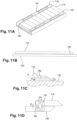
- the guide and return elements can be thin blades 151 in the form of loops positioned laterally between the frame 132 and the network of magnets 110 or the network of coils 120, as shown in the Figure 11A .
- These thin blades 151 can be formed from thin metallic ribbons or made from elastomers, such as those mentioned above, which have the advantage of great rigidity in the Y direction, normal to the planes PA, PB of the magnet networks and of coils, and great flexibility in the tangential direction Z.
- These loops 151 are connected to the moving part, for example to the network of magnets 110, on the one hand and to the frame 132 on the other hand.
- Such a constraint can be obtained by hindering means, such as a fluid 190 introduced into the interstitial space available between the network of magnets 110 and the network of coils 120, that is to say between the parts in reciprocal movement whose value desired thickness is preferably less than ten microns, as shown in the Figure 11B .
- a fluid 190 is held in place permanently thanks to the capillary force resulting from the use of a suitable fluid such as glycerin, ethylene glycol or refined mineral oil, which are not very toxic and have appropriate viscosities.
- Another embodiment of guidance in the direction normal Y to the plane PA and PB of the actuator can also consist of at least one pair of flanges 161 attached to the ends of the networks of magnets 110 and coils 120 in reciprocal movement.
- These flanges 161 can be formed from parts comprising two thin sections as illustrated by the Figure 11D .
- a quick calculation shows that if the displacement of a 2D amplitude of the networks of magnets 110 and coils 120 causes an inclination of plus or minus thirty degrees of the connecting bar 162, the variation in interstitial distance G will not exceed 14%.
- the vibrotactile actuator according to the invention can be inserted into or attached to any type of device to communicate haptic vibrations to said device. Indeed, if the plate 131 of the frame 130 is fixed to a structure to which the vibrations must be communicated, by application of the principle of conservation of angular momentum, at frequencies higher than the natural resonance frequency of the assembly made up of the mass in motion and the suspension formed by the network of magnets or the network of coils, the ratio of the speeds of the coils and the mass of the structure to be vibrated are in the inverse ratio of their reciprocal masses.
- Such an actuator due to its small dimensions, can be fixed, for example, on a watch bracelet type bracelet to communicate, by vibrations, the time to its user. It can also be fixed, for example, in a shoe sole, on clothing or on any element in contact with the user.
- the vibrotactile actuator according to the invention comprises various variants, modifications and improvements which will be obvious to those skilled in the art, it being understood that these variants , modifications and improvements are part of the scope of the invention.
Landscapes
- Engineering & Computer Science (AREA)
- Power Engineering (AREA)
- General Engineering & Computer Science (AREA)
- Physics & Mathematics (AREA)
- General Physics & Mathematics (AREA)
- Theoretical Computer Science (AREA)
- Human Computer Interaction (AREA)
- Reciprocating, Oscillating Or Vibrating Motors (AREA)
- Apparatuses For Generation Of Mechanical Vibrations (AREA)
- Signal Processing (AREA)
Applications Claiming Priority (2)
| Application Number | Priority Date | Filing Date | Title |
|---|---|---|---|
| FR1756450A FR3068840B1 (fr) | 2017-07-07 | 2017-07-07 | Actionneur vibrotactile |
| PCT/EP2018/068069 WO2019008021A1 (fr) | 2017-07-07 | 2018-07-04 | Actionneur vibrotactile |
Publications (3)
| Publication Number | Publication Date |
|---|---|
| EP3649726A1 EP3649726A1 (fr) | 2020-05-13 |
| EP3649726B1 true EP3649726B1 (fr) | 2023-11-22 |
| EP3649726C0 EP3649726C0 (fr) | 2023-11-22 |
Family
ID=60080959
Family Applications (1)
| Application Number | Title | Priority Date | Filing Date |
|---|---|---|---|
| EP18734256.3A Active EP3649726B1 (fr) | 2017-07-07 | 2018-07-04 | Actionneur vibrotactile |
Country Status (7)
| Country | Link |
|---|---|
| US (1) | US11289988B2 (https=) |
| EP (1) | EP3649726B1 (https=) |
| JP (2) | JP2020527105A (https=) |
| KR (1) | KR20200024922A (https=) |
| CA (1) | CA3068760A1 (https=) |
| FR (1) | FR3068840B1 (https=) |
| WO (1) | WO2019008021A1 (https=) |
Families Citing this family (11)
| Publication number | Priority date | Publication date | Assignee | Title |
|---|---|---|---|---|
| FR3097476B1 (fr) | 2019-06-24 | 2024-05-24 | Novares France | Boîtier d’actionnement pour fournir un retour haptique dans un véhicule |
| FR3106912A1 (fr) | 2020-01-30 | 2021-08-06 | Hap2U | Dispositif pour la création de sensations haptiques sur une surface à l’aide de vibrations elliptiques ultrasonores |
| US11483460B2 (en) | 2020-04-06 | 2022-10-25 | Apple Inc. | Multi-coil voice coil motor drive architecture |
| FR3110006B1 (fr) | 2020-04-27 | 2024-03-29 | Actronika | Dispositif haptique auto-adhésif |
| FR3109649B1 (fr) | 2020-04-27 | 2024-08-16 | Actronika | Dispositif haptique auto-adhésif |
| CN113589922B (zh) * | 2021-06-17 | 2024-03-01 | 汉得利(常州)电子股份有限公司 | 一种大行程弹片结构的触觉执行器 |
| US12099290B2 (en) * | 2021-06-23 | 2024-09-24 | New Shicoh Motor Co., Ltd | Blade driving device, camera device and electronic apparatus |
| US12576998B2 (en) * | 2021-07-13 | 2026-03-17 | Redwire Space, Inc. | Distributed drive systems and methods of use thereof |
| CN114604296B (zh) * | 2022-03-04 | 2023-10-31 | 中车青岛四方机车车辆股份有限公司 | 一种磁悬浮列车的定位系统及方法 |
| US20230305628A1 (en) * | 2022-03-22 | 2023-09-28 | City University Of Hong Kong | Bilateral vibrotactile actuator |
| US12357532B2 (en) | 2023-05-02 | 2025-07-15 | Gregory Scott Bishop | Soothing vibrotactile cuddle device |
Family Cites Families (27)
| Publication number | Priority date | Publication date | Assignee | Title |
|---|---|---|---|---|
| JPH09117721A (ja) * | 1994-09-28 | 1997-05-06 | Seiko Instr Inc | 振動モジュール |
| US6307287B1 (en) * | 1999-03-12 | 2001-10-23 | The Penn State Research Foundation | High-efficiency moving-magnet loudspeaker |
| JP3833607B2 (ja) | 2002-12-24 | 2006-10-18 | 帝国通信工業株式会社 | 振動発生器 |
| JP2005063150A (ja) * | 2003-08-12 | 2005-03-10 | Fujitsu Component Ltd | 座標入力装置 |
| JP4386807B2 (ja) * | 2004-07-29 | 2009-12-16 | 富士通コンポーネント株式会社 | 触覚パネル |
| JP2010082501A (ja) | 2008-09-29 | 2010-04-15 | Sanyo Electric Co Ltd | リニアモータおよびリニアモータを備える携帯機器 |
| KR100992264B1 (ko) | 2009-03-31 | 2010-11-05 | 삼성전기주식회사 | 리니어 진동 모터 |
| KR101090428B1 (ko) * | 2009-07-07 | 2011-12-07 | 삼성전기주식회사 | 선형 진동자 |
| KR101259683B1 (ko) * | 2010-10-27 | 2013-05-02 | 엘지이노텍 주식회사 | 수평 진동 모터 |
| US8878401B2 (en) * | 2010-11-10 | 2014-11-04 | Lg Innotek Co., Ltd. | Linear vibrator having a trembler with a magnet and a weight |
| CN102158039B (zh) | 2011-03-02 | 2013-01-09 | 上海交通大学 | 宽频微型电磁式振动能量采集器 |
| FR2984634B1 (fr) | 2011-12-19 | 2014-11-07 | Univ Pierre Et Marie Curie Paris 6 | Actionneur vitrotactile lineaire miniature |
| DE102013110029C5 (de) * | 2013-09-12 | 2017-03-16 | Bürkert Werke GmbH | Elektrodynamischer Aktor |
| US9607491B1 (en) * | 2013-09-18 | 2017-03-28 | Bruce J. P. Mortimer | Apparatus for generating a vibrational stimulus using a planar reciprocating actuator |
| CN204425641U (zh) | 2015-01-29 | 2015-06-24 | 瑞声科技(南京)有限公司 | 电磁扬声器 |
| CN104617735B (zh) * | 2015-02-02 | 2017-09-08 | 瑞声光电科技(常州)有限公司 | 扁平线性振动电机 |
| WO2016167299A1 (ja) | 2015-04-17 | 2016-10-20 | 日本電産コパル株式会社 | リニア振動モータ |
| JP6531261B2 (ja) | 2015-10-16 | 2019-06-19 | 日本電産セイミツ株式会社 | 振動モータ |
| CN205160331U (zh) | 2015-10-26 | 2016-04-13 | 南昌航空大学 | 一种新型的惯性作动器 |
| JP6748342B2 (ja) | 2015-11-13 | 2020-09-02 | ミツミ電機株式会社 | 振動アクチュエータ、ウェアラブル端末及び着信通知機能デバイス |
| JP2017108594A (ja) * | 2015-12-11 | 2017-06-15 | 日本電産株式会社 | 振動モータ |
| CN205453449U (zh) | 2016-03-16 | 2016-08-10 | 宁波赛嘉电器有限公司 | 一种电机 |
| CN105871165B (zh) * | 2016-03-31 | 2019-10-18 | 金龙机电股份有限公司 | 一种线性电机 |
| CN105680663A (zh) * | 2016-04-19 | 2016-06-15 | 金龙机电股份有限公司 | 一种线性电机 |
| CN105990927B (zh) * | 2016-06-01 | 2019-02-15 | 歌尔股份有限公司 | 用于振动马达的磁体单元及一种线性振动马达 |
| JP6113338B2 (ja) | 2016-07-26 | 2017-04-12 | ミネベアミツミ株式会社 | 振動発生器 |
| US9942663B1 (en) * | 2016-12-22 | 2018-04-10 | Apple Inc. | Electromagnetic transducer having paired Halbach arrays |
-
2017
- 2017-07-07 FR FR1756450A patent/FR3068840B1/fr active Active
-
2018
- 2018-07-04 KR KR1020207003491A patent/KR20200024922A/ko not_active Ceased
- 2018-07-04 CA CA3068760A patent/CA3068760A1/fr active Pending
- 2018-07-04 EP EP18734256.3A patent/EP3649726B1/fr active Active
- 2018-07-04 JP JP2020522782A patent/JP2020527105A/ja not_active Ceased
- 2018-07-04 WO PCT/EP2018/068069 patent/WO2019008021A1/fr not_active Ceased
- 2018-07-04 US US16/628,885 patent/US11289988B2/en active Active
-
2023
- 2023-11-30 JP JP2023202481A patent/JP2024023462A/ja active Pending
Also Published As
| Publication number | Publication date |
|---|---|
| FR3068840B1 (fr) | 2023-03-31 |
| WO2019008021A1 (fr) | 2019-01-10 |
| JP2024023462A (ja) | 2024-02-21 |
| CA3068760A1 (fr) | 2019-01-10 |
| EP3649726A1 (fr) | 2020-05-13 |
| US20200235649A1 (en) | 2020-07-23 |
| US11289988B2 (en) | 2022-03-29 |
| KR20200024922A (ko) | 2020-03-09 |
| JP2020527105A (ja) | 2020-09-03 |
| FR3068840A1 (fr) | 2019-01-11 |
| EP3649726C0 (fr) | 2023-11-22 |
Similar Documents
| Publication | Publication Date | Title |
|---|---|---|
| EP3649726B1 (fr) | Actionneur vibrotactile | |
| EP2795773B1 (fr) | Actionneur vibrotactile linéaire miniature | |
| JP7265266B2 (ja) | リニア振動アクチュエータ | |
| CN105281533B (zh) | 线性致动器 | |
| WO2010026883A1 (ja) | リニアモータおよびリニアモータを備えた携帯機器 | |
| JP5237338B2 (ja) | マグネット発振器 | |
| EP1005714A1 (fr) | Actionneur electromagnetique a deux pieces mobiles en opposition de phases | |
| JP7371926B2 (ja) | リニア振動モータ | |
| EP2862210A1 (fr) | Actionneur pour moteur ultrasonique et moteur ultrasonique comportant au moins un tel actionneur | |
| WO2015114261A1 (fr) | Actionneur electromagnetique lineaire presentant deux organes mobiles independants | |
| JP2018160999A (ja) | リニア振動モータ | |
| TW201008103A (en) | Ultrasonic linear motor | |
| CN103023266A (zh) | 线性振动器 | |
| JP2010082508A (ja) | 振動モータおよびそれを用いた携帯端末装置 | |
| WO2010026709A1 (ja) | 振動モータおよびそれを用いた携帯端末装置 | |
| CN107026556A (zh) | 双逆磁式线性震动致动器 | |
| CN107546949B (zh) | 水平线性振动电机 | |
| JP2010099642A (ja) | 振動モータおよびそれを用いた携帯端末装置 | |
| WO2011061832A1 (ja) | 駆動装置 | |
| JP2005210852A (ja) | 静電モータ | |
| JP2009044949A (ja) | 動作装置 | |
| KR101362586B1 (ko) | 소형의 기능성 진동발생장치 | |
| EP1659676A1 (fr) | Vibreur pour un objet portable | |
| CN107026554B (zh) | 可复位的双逆磁式线性震动致动器 | |
| KR101737942B1 (ko) | 박형 선형 진동자 |
Legal Events
| Date | Code | Title | Description |
|---|---|---|---|
| STAA | Information on the status of an ep patent application or granted ep patent |
Free format text: STATUS: UNKNOWN |
|
| STAA | Information on the status of an ep patent application or granted ep patent |
Free format text: STATUS: THE INTERNATIONAL PUBLICATION HAS BEEN MADE |
|
| PUAI | Public reference made under article 153(3) epc to a published international application that has entered the european phase |
Free format text: ORIGINAL CODE: 0009012 |
|
| STAA | Information on the status of an ep patent application or granted ep patent |
Free format text: STATUS: REQUEST FOR EXAMINATION WAS MADE |
|
| 17P | Request for examination filed |
Effective date: 20200203 |
|
| AK | Designated contracting states |
Kind code of ref document: A1 Designated state(s): AL AT BE BG CH CY CZ DE DK EE ES FI FR GB GR HR HU IE IS IT LI LT LU LV MC MK MT NL NO PL PT RO RS SE SI SK SM TR |
|
| AX | Request for extension of the european patent |
Extension state: BA ME |
|
| DAV | Request for validation of the european patent (deleted) | ||
| DAX | Request for extension of the european patent (deleted) | ||
| STAA | Information on the status of an ep patent application or granted ep patent |
Free format text: STATUS: EXAMINATION IS IN PROGRESS |
|
| 17Q | First examination report despatched |
Effective date: 20210211 |
|
| REG | Reference to a national code |
Ref country code: DE Ref legal event code: R079 Free format text: PREVIOUS MAIN CLASS: H02K0033040000 Ipc: H02K0033160000 Ref document number: 602018061420 Country of ref document: DE |
|
| RIC1 | Information provided on ipc code assigned before grant |
Ipc: G06F 3/01 20060101ALI20230331BHEP Ipc: H02K 33/04 20060101ALI20230331BHEP Ipc: H02K 33/16 20060101AFI20230331BHEP |
|
| GRAP | Despatch of communication of intention to grant a patent |
Free format text: ORIGINAL CODE: EPIDOSNIGR1 |
|
| STAA | Information on the status of an ep patent application or granted ep patent |
Free format text: STATUS: GRANT OF PATENT IS INTENDED |
|
| INTG | Intention to grant announced |
Effective date: 20230627 |
|
| GRAS | Grant fee paid |
Free format text: ORIGINAL CODE: EPIDOSNIGR3 |
|
| GRAA | (expected) grant |
Free format text: ORIGINAL CODE: 0009210 |
|
| STAA | Information on the status of an ep patent application or granted ep patent |
Free format text: STATUS: THE PATENT HAS BEEN GRANTED |
|
| AK | Designated contracting states |
Kind code of ref document: B1 Designated state(s): AL AT BE BG CH CY CZ DE DK EE ES FI FR GB GR HR HU IE IS IT LI LT LU LV MC MK MT NL NO PL PT RO RS SE SI SK SM TR |
|
| REG | Reference to a national code |
Ref country code: GB Ref legal event code: FG4D Free format text: NOT ENGLISH |
|
| REG | Reference to a national code |
Ref country code: CH Ref legal event code: EP |
|
| REG | Reference to a national code |
Ref country code: DE Ref legal event code: R096 Ref document number: 602018061420 Country of ref document: DE |
|
| REG | Reference to a national code |
Ref country code: IE Ref legal event code: FG4D Free format text: LANGUAGE OF EP DOCUMENT: FRENCH |
|
| U01 | Request for unitary effect filed |
Effective date: 20231208 |
|
| U07 | Unitary effect registered |
Designated state(s): AT BE BG DE DK EE FI FR IT LT LU LV MT NL PT SE SI Effective date: 20231222 |
|
| PG25 | Lapsed in a contracting state [announced via postgrant information from national office to epo] |
Ref country code: GR Free format text: LAPSE BECAUSE OF FAILURE TO SUBMIT A TRANSLATION OF THE DESCRIPTION OR TO PAY THE FEE WITHIN THE PRESCRIBED TIME-LIMIT Effective date: 20240223 |
|
| PG25 | Lapsed in a contracting state [announced via postgrant information from national office to epo] |
Ref country code: IS Free format text: LAPSE BECAUSE OF FAILURE TO SUBMIT A TRANSLATION OF THE DESCRIPTION OR TO PAY THE FEE WITHIN THE PRESCRIBED TIME-LIMIT Effective date: 20240322 |
|
| PG25 | Lapsed in a contracting state [announced via postgrant information from national office to epo] |
Ref country code: ES Free format text: LAPSE BECAUSE OF FAILURE TO SUBMIT A TRANSLATION OF THE DESCRIPTION OR TO PAY THE FEE WITHIN THE PRESCRIBED TIME-LIMIT Effective date: 20231122 |
|
| PG25 | Lapsed in a contracting state [announced via postgrant information from national office to epo] |
Ref country code: IS Free format text: LAPSE BECAUSE OF FAILURE TO SUBMIT A TRANSLATION OF THE DESCRIPTION OR TO PAY THE FEE WITHIN THE PRESCRIBED TIME-LIMIT Effective date: 20240322 Ref country code: GR Free format text: LAPSE BECAUSE OF FAILURE TO SUBMIT A TRANSLATION OF THE DESCRIPTION OR TO PAY THE FEE WITHIN THE PRESCRIBED TIME-LIMIT Effective date: 20240223 Ref country code: ES Free format text: LAPSE BECAUSE OF FAILURE TO SUBMIT A TRANSLATION OF THE DESCRIPTION OR TO PAY THE FEE WITHIN THE PRESCRIBED TIME-LIMIT Effective date: 20231122 |
|
| PG25 | Lapsed in a contracting state [announced via postgrant information from national office to epo] |
Ref country code: RS Free format text: LAPSE BECAUSE OF FAILURE TO SUBMIT A TRANSLATION OF THE DESCRIPTION OR TO PAY THE FEE WITHIN THE PRESCRIBED TIME-LIMIT Effective date: 20231122 Ref country code: PL Free format text: LAPSE BECAUSE OF FAILURE TO SUBMIT A TRANSLATION OF THE DESCRIPTION OR TO PAY THE FEE WITHIN THE PRESCRIBED TIME-LIMIT Effective date: 20231122 Ref country code: NO Free format text: LAPSE BECAUSE OF FAILURE TO SUBMIT A TRANSLATION OF THE DESCRIPTION OR TO PAY THE FEE WITHIN THE PRESCRIBED TIME-LIMIT Effective date: 20240222 Ref country code: HR Free format text: LAPSE BECAUSE OF FAILURE TO SUBMIT A TRANSLATION OF THE DESCRIPTION OR TO PAY THE FEE WITHIN THE PRESCRIBED TIME-LIMIT Effective date: 20231122 |
|
| PG25 | Lapsed in a contracting state [announced via postgrant information from national office to epo] |
Ref country code: CZ Free format text: LAPSE BECAUSE OF FAILURE TO SUBMIT A TRANSLATION OF THE DESCRIPTION OR TO PAY THE FEE WITHIN THE PRESCRIBED TIME-LIMIT Effective date: 20231122 |
|
| PG25 | Lapsed in a contracting state [announced via postgrant information from national office to epo] |
Ref country code: SK Free format text: LAPSE BECAUSE OF FAILURE TO SUBMIT A TRANSLATION OF THE DESCRIPTION OR TO PAY THE FEE WITHIN THE PRESCRIBED TIME-LIMIT Effective date: 20231122 |
|
| PG25 | Lapsed in a contracting state [announced via postgrant information from national office to epo] |
Ref country code: SM Free format text: LAPSE BECAUSE OF FAILURE TO SUBMIT A TRANSLATION OF THE DESCRIPTION OR TO PAY THE FEE WITHIN THE PRESCRIBED TIME-LIMIT Effective date: 20231122 Ref country code: SK Free format text: LAPSE BECAUSE OF FAILURE TO SUBMIT A TRANSLATION OF THE DESCRIPTION OR TO PAY THE FEE WITHIN THE PRESCRIBED TIME-LIMIT Effective date: 20231122 Ref country code: RO Free format text: LAPSE BECAUSE OF FAILURE TO SUBMIT A TRANSLATION OF THE DESCRIPTION OR TO PAY THE FEE WITHIN THE PRESCRIBED TIME-LIMIT Effective date: 20231122 Ref country code: CZ Free format text: LAPSE BECAUSE OF FAILURE TO SUBMIT A TRANSLATION OF THE DESCRIPTION OR TO PAY THE FEE WITHIN THE PRESCRIBED TIME-LIMIT Effective date: 20231122 |
|
| REG | Reference to a national code |
Ref country code: DE Ref legal event code: R097 Ref document number: 602018061420 Country of ref document: DE |
|
| U20 | Renewal fee for the european patent with unitary effect paid |
Year of fee payment: 7 Effective date: 20240729 |
|
| PLBE | No opposition filed within time limit |
Free format text: ORIGINAL CODE: 0009261 |
|
| STAA | Information on the status of an ep patent application or granted ep patent |
Free format text: STATUS: NO OPPOSITION FILED WITHIN TIME LIMIT |
|
| PGFP | Annual fee paid to national office [announced via postgrant information from national office to epo] |
Ref country code: GB Payment date: 20240827 Year of fee payment: 7 |
|
| 26N | No opposition filed |
Effective date: 20240823 |
|
| PGFP | Annual fee paid to national office [announced via postgrant information from national office to epo] |
Ref country code: IE Payment date: 20241024 Year of fee payment: 7 |
|
| PG25 | Lapsed in a contracting state [announced via postgrant information from national office to epo] |
Ref country code: MC Free format text: LAPSE BECAUSE OF FAILURE TO SUBMIT A TRANSLATION OF THE DESCRIPTION OR TO PAY THE FEE WITHIN THE PRESCRIBED TIME-LIMIT Effective date: 20231122 |
|
| REG | Reference to a national code |
Ref country code: CH Ref legal event code: PL |
|
| PG25 | Lapsed in a contracting state [announced via postgrant information from national office to epo] |
Ref country code: CH Free format text: LAPSE BECAUSE OF NON-PAYMENT OF DUE FEES Effective date: 20240731 |
|
| PG25 | Lapsed in a contracting state [announced via postgrant information from national office to epo] |
Ref country code: CY Free format text: LAPSE BECAUSE OF FAILURE TO SUBMIT A TRANSLATION OF THE DESCRIPTION OR TO PAY THE FEE WITHIN THE PRESCRIBED TIME-LIMIT; INVALID AB INITIO Effective date: 20180704 |
|
| U21 | Renewal fee for the european patent with unitary effect paid with additional fee |
Year of fee payment: 8 Effective date: 20260121 |
|
| PG25 | Lapsed in a contracting state [announced via postgrant information from national office to epo] |
Ref country code: HU Free format text: LAPSE BECAUSE OF FAILURE TO SUBMIT A TRANSLATION OF THE DESCRIPTION OR TO PAY THE FEE WITHIN THE PRESCRIBED TIME-LIMIT; INVALID AB INITIO Effective date: 20180704 |
|
| GBPC | Gb: european patent ceased through non-payment of renewal fee |
Effective date: 20250704 |
|
| PG25 | Lapsed in a contracting state [announced via postgrant information from national office to epo] |
Ref country code: GB Free format text: LAPSE BECAUSE OF NON-PAYMENT OF DUE FEES Effective date: 20250704 |