EP3648706B1 - Prosthetic heart valve devices - Google Patents
Prosthetic heart valve devices Download PDFInfo
- Publication number
- EP3648706B1 EP3648706B1 EP18740434.8A EP18740434A EP3648706B1 EP 3648706 B1 EP3648706 B1 EP 3648706B1 EP 18740434 A EP18740434 A EP 18740434A EP 3648706 B1 EP3648706 B1 EP 3648706B1
- Authority
- EP
- European Patent Office
- Prior art keywords
- extension member
- terminus
- valve
- fixation structure
- length
- Prior art date
- Legal status (The legal status is an assumption and is not a legal conclusion. Google has not performed a legal analysis and makes no representation as to the accuracy of the status listed.)
- Active
Links
- 210000003709 heart valve Anatomy 0.000 title claims description 30
- 238000004873 anchoring Methods 0.000 claims description 26
- 238000011144 upstream manufacturing Methods 0.000 claims description 12
- 230000017531 blood circulation Effects 0.000 claims description 7
- 210000004115 mitral valve Anatomy 0.000 description 54
- 238000013459 approach Methods 0.000 description 33
- 238000005516 engineering process Methods 0.000 description 24
- 238000007789 sealing Methods 0.000 description 24
- 210000002216 heart Anatomy 0.000 description 20
- 238000000034 method Methods 0.000 description 20
- 210000001765 aortic valve Anatomy 0.000 description 19
- 239000000463 material Substances 0.000 description 13
- 210000001519 tissue Anatomy 0.000 description 10
- 210000005240 left ventricle Anatomy 0.000 description 9
- 210000004971 interatrial septum Anatomy 0.000 description 7
- 210000005246 left atrium Anatomy 0.000 description 7
- 239000002184 metal Substances 0.000 description 7
- 210000005166 vasculature Anatomy 0.000 description 7
- 210000004369 blood Anatomy 0.000 description 6
- 239000008280 blood Substances 0.000 description 6
- 210000003484 anatomy Anatomy 0.000 description 5
- 208000005907 mitral valve insufficiency Diseases 0.000 description 5
- MWCLLHOVUTZFKS-UHFFFAOYSA-N Methyl cyanoacrylate Chemical compound COC(=O)C(=C)C#N MWCLLHOVUTZFKS-UHFFFAOYSA-N 0.000 description 4
- 239000004744 fabric Substances 0.000 description 4
- 230000003387 muscular Effects 0.000 description 4
- 230000001746 atrial effect Effects 0.000 description 3
- 210000003540 papillary muscle Anatomy 0.000 description 3
- 208000003430 Mitral Valve Prolapse Diseases 0.000 description 2
- 230000002159 abnormal effect Effects 0.000 description 2
- 210000002376 aorta thoracic Anatomy 0.000 description 2
- 230000009286 beneficial effect Effects 0.000 description 2
- 230000000747 cardiac effect Effects 0.000 description 2
- 210000003698 chordae tendineae Anatomy 0.000 description 2
- 238000002513 implantation Methods 0.000 description 2
- 230000003601 intercostal effect Effects 0.000 description 2
- 230000001788 irregular Effects 0.000 description 2
- 208000006887 mitral valve stenosis Diseases 0.000 description 2
- 210000005245 right atrium Anatomy 0.000 description 2
- 210000001631 vena cava inferior Anatomy 0.000 description 2
- 230000002861 ventricular Effects 0.000 description 2
- 229920004934 Dacron® Polymers 0.000 description 1
- 208000012287 Prolapse Diseases 0.000 description 1
- 239000000853 adhesive Substances 0.000 description 1
- 230000001070 adhesive effect Effects 0.000 description 1
- 210000000709 aorta Anatomy 0.000 description 1
- 210000005249 arterial vasculature Anatomy 0.000 description 1
- 210000001367 artery Anatomy 0.000 description 1
- 210000004191 axillary artery Anatomy 0.000 description 1
- 210000002302 brachial artery Anatomy 0.000 description 1
- 239000002775 capsule Substances 0.000 description 1
- 210000001715 carotid artery Anatomy 0.000 description 1
- 210000000038 chest Anatomy 0.000 description 1
- 230000001010 compromised effect Effects 0.000 description 1
- 230000008602 contraction Effects 0.000 description 1
- 230000001419 dependent effect Effects 0.000 description 1
- 238000013461 design Methods 0.000 description 1
- 230000010339 dilation Effects 0.000 description 1
- 208000037265 diseases, disorders, signs and symptoms Diseases 0.000 description 1
- 239000002934 diuretic Substances 0.000 description 1
- 229940030606 diuretics Drugs 0.000 description 1
- 230000000694 effects Effects 0.000 description 1
- 210000001105 femoral artery Anatomy 0.000 description 1
- 210000004491 foramen ovale Anatomy 0.000 description 1
- 208000019622 heart disease Diseases 0.000 description 1
- 208000028867 ischemia Diseases 0.000 description 1
- 230000007257 malfunction Effects 0.000 description 1
- 238000002324 minimally invasive surgery Methods 0.000 description 1
- 210000004165 myocardium Anatomy 0.000 description 1
- HLXZNVUGXRDIFK-UHFFFAOYSA-N nickel titanium Chemical compound [Ti].[Ti].[Ti].[Ti].[Ti].[Ti].[Ti].[Ti].[Ti].[Ti].[Ti].[Ni].[Ni].[Ni].[Ni].[Ni].[Ni].[Ni].[Ni].[Ni].[Ni].[Ni].[Ni].[Ni].[Ni] HLXZNVUGXRDIFK-UHFFFAOYSA-N 0.000 description 1
- 229910001000 nickel titanium Inorganic materials 0.000 description 1
- 239000005020 polyethylene terephthalate Substances 0.000 description 1
- 229920000642 polymer Polymers 0.000 description 1
- 210000002321 radial artery Anatomy 0.000 description 1
- 238000011084 recovery Methods 0.000 description 1
- 238000004513 sizing Methods 0.000 description 1
- 230000006641 stabilisation Effects 0.000 description 1
- 238000011105 stabilization Methods 0.000 description 1
- 238000001356 surgical procedure Methods 0.000 description 1
- 210000002435 tendon Anatomy 0.000 description 1
- 210000000115 thoracic cavity Anatomy 0.000 description 1
- 238000012549 training Methods 0.000 description 1
- 238000012546 transfer Methods 0.000 description 1
- 230000001131 transforming effect Effects 0.000 description 1
- 210000000591 tricuspid valve Anatomy 0.000 description 1
- 208000028073 tricuspid valve disease Diseases 0.000 description 1
- 230000002792 vascular Effects 0.000 description 1
- 229940124549 vasodilator Drugs 0.000 description 1
- 239000003071 vasodilator agent Substances 0.000 description 1
- 210000003462 vein Anatomy 0.000 description 1
- 210000002620 vena cava superior Anatomy 0.000 description 1
Images
Classifications
-
- A—HUMAN NECESSITIES
- A61—MEDICAL OR VETERINARY SCIENCE; HYGIENE
- A61F—FILTERS IMPLANTABLE INTO BLOOD VESSELS; PROSTHESES; DEVICES PROVIDING PATENCY TO, OR PREVENTING COLLAPSING OF, TUBULAR STRUCTURES OF THE BODY, e.g. STENTS; ORTHOPAEDIC, NURSING OR CONTRACEPTIVE DEVICES; FOMENTATION; TREATMENT OR PROTECTION OF EYES OR EARS; BANDAGES, DRESSINGS OR ABSORBENT PADS; FIRST-AID KITS
- A61F2/00—Filters implantable into blood vessels; Prostheses, i.e. artificial substitutes or replacements for parts of the body; Appliances for connecting them with the body; Devices providing patency to, or preventing collapsing of, tubular structures of the body, e.g. stents
- A61F2/02—Prostheses implantable into the body
- A61F2/24—Heart valves ; Vascular valves, e.g. venous valves; Heart implants, e.g. passive devices for improving the function of the native valve or the heart muscle; Transmyocardial revascularisation [TMR] devices; Valves implantable in the body
- A61F2/2412—Heart valves ; Vascular valves, e.g. venous valves; Heart implants, e.g. passive devices for improving the function of the native valve or the heart muscle; Transmyocardial revascularisation [TMR] devices; Valves implantable in the body with soft flexible valve members, e.g. tissue valves shaped like natural valves
- A61F2/2418—Scaffolds therefor, e.g. support stents
-
- A—HUMAN NECESSITIES
- A61—MEDICAL OR VETERINARY SCIENCE; HYGIENE
- A61B—DIAGNOSIS; SURGERY; IDENTIFICATION
- A61B5/00—Measuring for diagnostic purposes; Identification of persons
- A61B5/06—Devices, other than using radiation, for detecting or locating foreign bodies ; determining position of probes within or on the body of the patient
- A61B5/065—Determining position of the probe employing exclusively positioning means located on or in the probe, e.g. using position sensors arranged on the probe
- A61B5/068—Determining position of the probe employing exclusively positioning means located on or in the probe, e.g. using position sensors arranged on the probe using impedance sensors
-
- A—HUMAN NECESSITIES
- A61—MEDICAL OR VETERINARY SCIENCE; HYGIENE
- A61F—FILTERS IMPLANTABLE INTO BLOOD VESSELS; PROSTHESES; DEVICES PROVIDING PATENCY TO, OR PREVENTING COLLAPSING OF, TUBULAR STRUCTURES OF THE BODY, e.g. STENTS; ORTHOPAEDIC, NURSING OR CONTRACEPTIVE DEVICES; FOMENTATION; TREATMENT OR PROTECTION OF EYES OR EARS; BANDAGES, DRESSINGS OR ABSORBENT PADS; FIRST-AID KITS
- A61F2/00—Filters implantable into blood vessels; Prostheses, i.e. artificial substitutes or replacements for parts of the body; Appliances for connecting them with the body; Devices providing patency to, or preventing collapsing of, tubular structures of the body, e.g. stents
- A61F2/02—Prostheses implantable into the body
- A61F2/24—Heart valves ; Vascular valves, e.g. venous valves; Heart implants, e.g. passive devices for improving the function of the native valve or the heart muscle; Transmyocardial revascularisation [TMR] devices; Valves implantable in the body
- A61F2/2412—Heart valves ; Vascular valves, e.g. venous valves; Heart implants, e.g. passive devices for improving the function of the native valve or the heart muscle; Transmyocardial revascularisation [TMR] devices; Valves implantable in the body with soft flexible valve members, e.g. tissue valves shaped like natural valves
-
- A—HUMAN NECESSITIES
- A61—MEDICAL OR VETERINARY SCIENCE; HYGIENE
- A61F—FILTERS IMPLANTABLE INTO BLOOD VESSELS; PROSTHESES; DEVICES PROVIDING PATENCY TO, OR PREVENTING COLLAPSING OF, TUBULAR STRUCTURES OF THE BODY, e.g. STENTS; ORTHOPAEDIC, NURSING OR CONTRACEPTIVE DEVICES; FOMENTATION; TREATMENT OR PROTECTION OF EYES OR EARS; BANDAGES, DRESSINGS OR ABSORBENT PADS; FIRST-AID KITS
- A61F2/00—Filters implantable into blood vessels; Prostheses, i.e. artificial substitutes or replacements for parts of the body; Appliances for connecting them with the body; Devices providing patency to, or preventing collapsing of, tubular structures of the body, e.g. stents
- A61F2/02—Prostheses implantable into the body
- A61F2/24—Heart valves ; Vascular valves, e.g. venous valves; Heart implants, e.g. passive devices for improving the function of the native valve or the heart muscle; Transmyocardial revascularisation [TMR] devices; Valves implantable in the body
- A61F2/2427—Devices for manipulating or deploying heart valves during implantation
- A61F2/243—Deployment by mechanical expansion
-
- A—HUMAN NECESSITIES
- A61—MEDICAL OR VETERINARY SCIENCE; HYGIENE
- A61F—FILTERS IMPLANTABLE INTO BLOOD VESSELS; PROSTHESES; DEVICES PROVIDING PATENCY TO, OR PREVENTING COLLAPSING OF, TUBULAR STRUCTURES OF THE BODY, e.g. STENTS; ORTHOPAEDIC, NURSING OR CONTRACEPTIVE DEVICES; FOMENTATION; TREATMENT OR PROTECTION OF EYES OR EARS; BANDAGES, DRESSINGS OR ABSORBENT PADS; FIRST-AID KITS
- A61F2210/00—Particular material properties of prostheses classified in groups A61F2/00 - A61F2/26 or A61F2/82 or A61F9/00 or A61F11/00 or subgroups thereof
- A61F2210/0014—Particular material properties of prostheses classified in groups A61F2/00 - A61F2/26 or A61F2/82 or A61F9/00 or A61F11/00 or subgroups thereof using shape memory or superelastic materials, e.g. nitinol
-
- A—HUMAN NECESSITIES
- A61—MEDICAL OR VETERINARY SCIENCE; HYGIENE
- A61F—FILTERS IMPLANTABLE INTO BLOOD VESSELS; PROSTHESES; DEVICES PROVIDING PATENCY TO, OR PREVENTING COLLAPSING OF, TUBULAR STRUCTURES OF THE BODY, e.g. STENTS; ORTHOPAEDIC, NURSING OR CONTRACEPTIVE DEVICES; FOMENTATION; TREATMENT OR PROTECTION OF EYES OR EARS; BANDAGES, DRESSINGS OR ABSORBENT PADS; FIRST-AID KITS
- A61F2250/00—Special features of prostheses classified in groups A61F2/00 - A61F2/26 or A61F2/82 or A61F9/00 or A61F11/00 or subgroups thereof
- A61F2250/0001—Means for transferring electromagnetic energy to implants
- A61F2250/0002—Means for transferring electromagnetic energy to implants for data transfer
-
- A—HUMAN NECESSITIES
- A61—MEDICAL OR VETERINARY SCIENCE; HYGIENE
- A61F—FILTERS IMPLANTABLE INTO BLOOD VESSELS; PROSTHESES; DEVICES PROVIDING PATENCY TO, OR PREVENTING COLLAPSING OF, TUBULAR STRUCTURES OF THE BODY, e.g. STENTS; ORTHOPAEDIC, NURSING OR CONTRACEPTIVE DEVICES; FOMENTATION; TREATMENT OR PROTECTION OF EYES OR EARS; BANDAGES, DRESSINGS OR ABSORBENT PADS; FIRST-AID KITS
- A61F2250/00—Special features of prostheses classified in groups A61F2/00 - A61F2/26 or A61F2/82 or A61F9/00 or A61F11/00 or subgroups thereof
- A61F2250/0058—Additional features; Implant or prostheses properties not otherwise provided for
- A61F2250/0096—Markers and sensors for detecting a position or changes of a position of an implant, e.g. RF sensors, ultrasound markers
- A61F2250/0098—Markers and sensors for detecting a position or changes of a position of an implant, e.g. RF sensors, ultrasound markers radio-opaque, e.g. radio-opaque markers
Definitions
- the present application refers to the subject matter of (1) International Patent Application No. PCT/US2014/029549, filed March 14, 2014 , (2) International Patent Application No. PCT/US2012/061219, filed October 19, 2012 , (3) International Patent Application No. PCT/US2012/061215, filed October 19, 2012 , (4) International Patent Application No. PCT/US2012/043636, filed June 21, 2012 .
- the present application also refers to the subject matter of U.S. Application No. 15/642,834 (Attorney Docket No. C00013623.USU1), filed concurrently herewith, and U.S. Application No. 15/642,834 (Attorney Docket No. C00013493.USU2), also filed concurrently herewith.
- the present technology relates generally to prosthetic heart valve devices.
- several embodiments are directed to prosthetic mitral valves and devices for percutaneous repair and/or replacement of native mitral valves and associated systems.
- Mitral valves can be affected by mitral valve regurgitation, mitral valve prolapse and mitral valve stenosis.
- Mitral valve regurgitation is abnormal leaking of blood from the left ventricle into the left atrium caused by a disorder of the heart in which the leaflets of the mitral valve fail to coapt into apposition at peak contraction pressures.
- the mitral valve leaflets may not coapt sufficiently because heart diseases often cause dilation of the heart muscle, which in turn enlarges the native mitral valve annulus to the extent that the leaflets do not coapt during systole.
- Abnormal backflow can also occur when the papillary muscles are functionally compromised due to ischemia or other conditions. More specifically, as the left ventricle contracts during systole, the affected papillary muscles do not contract sufficiently to effect proper closure of the leaflets.
- Mitral valve prolapse is a condition when the mitral leaflets bulge abnormally up in to the left atrium. This can cause irregular behavior of the mitral valve and lead to mitral valve regurgitation.
- the leaflets may prolapse and fail to coapt because the tendons connecting the papillary muscles to the inferior side of the mitral valve leaflets (chordae tendineae) may tear or stretch.
- Mitral valve stenosis is a narrowing of the mitral valve orifice that impedes filling of the left ventricle in diastole.
- Mitral valve regurgitation is often treated using diuretics and/or vasodilators to reduce the amount of blood flowing back into the left atrium.
- Surgical approaches open and intravascular for either the repair or replacement of the valve have also been used to treat mitral valve regurgitation.
- typical repair techniques involve cinching or resecting portions of the dilated annulus. Cinching, for example, includes implanting annular or peri-annular rings that are generally secured to the annulus or surrounding tissue. Other repair procedures suture or clip the valve leaflets into partial apposition with one another.
- aortic valve replacement Less invasive approaches to aortic valve replacement have been implemented in recent years.
- pre-assembled, percutaneous prosthetic valves include, e.g., the CoreValve Revalving ® System from Medtronic/Corevalve Inc. (Irvine, CA, USA) and the Edwards-Sapien ® Valve from Edwards Lifesciences (Irvine, CA, USA). Both valve systems include an expandable frame and a tri-leaflet bioprosthetic valve attached to the expandable frame.
- the aortic valve is substantially symmetric, circular, and has a muscular annulus.
- aortic valve anatomy lends itself to an expandable frame housing a replacement valve since the aortic valve anatomy is substantially uniform, symmetric, and fairly muscular.
- Other heart valve anatomies are not uniform, symmetric or sufficiently muscular, and thus transvascular aortic valve replacement devises may not be well suited for other types of heart valves.
- the triscuspid valve on the right side of the heart although it normally has three leaflets, poses similar challenges to less invasive treatment as the mitral valve. Therefore there is a need for a better prosthesis to treat tricuspid valve disease as well.
- EP 2 695 586 A1 relates to a valve prosthesis and kit.
- WO2014/144937A2 discloses a valve prosthesis.
- distal and proximal within this description, unless otherwise specified, the terms can reference a relative position of the portions of a prosthetic valve device and/or an associated delivery device with reference to an operator and/or a location in the vasculature or heart.
- proximal can refer to a position closer to the operator of the device or an incision into the vasculature
- distal can refer to a position that is more distant from the operator of the device or further from the incision along the vasculature (e.g., the end of the catheter).
- proximal and distal can refer to the location of portions of the device with respect to the direction of blood flow.
- proximal can refer to an upstream position or a location where blood flows into the device (e.g., inflow region)
- distal can refer to a downstream position or a location where blood flows out of the device (e.g., outflow region).
- Several embodiments of the present technology are directed to mitral valve replacement devices that address the unique challenges of percutaneously replacing native mitral valves and are well-suited for navigating through the heart anatomy to the mitral valve annulus.
- percutaneous mitral valve replacement faces unique anatomical obstacles that render percutaneous mitral valve replacement significantly more challenging than aortic valve replacement.
- the mitral valve annulus has a non-circular D-shape or kidney-like shape, with a non-planar, saddle-like geometry often lacking symmetry.
- the complex and highly variable anatomy of mitral valves makes it difficult to design a mitral valve prosthesis that conforms well to the native mitral annulus of specific patients.
- the prosthesis may not fit well with the native leaflets and/or annulus, which can leave gaps that allows backflow of blood to occur.
- placement of a cylindrical valve prosthesis in a native mitral valve may leave gaps in commissural regions of the native valve through which perivalvular leaks may occur.
- a diseased mitral annulus is much larger than any available prosthetic aortic valve.
- the forces on the valve leaflets increase dramatically, so simply increasing the size of an aortic prosthesis to the size of a dilated mitral valve annulus would require dramatically thicker, taller leaflets, and might not be feasible.
- mitral valve annulus In addition to its irregular, complex shape, which changes size over the course of each heartbeat, the mitral valve annulus lacks a significant amount of radial support from surrounding tissue. Compared to aortic valves, which are completely surrounded by fibro-elastic tissue that provides sufficient support for anchoring a prosthetic valve, mitral valves are bound by muscular tissue on the outer wall only. The inner wall of the mitral valve anatomy is bound by a thin vessel wall separating the mitral valve annulus from the inferior portion of the aortic outflow tract. As a result, significant radial forces on the mitral annulus, such as those imparted by an expanding stent prostheses, could lead to collapse of the inferior portion of the aortic tract. Moreover, larger prostheses exert more force and expand to larger dimensions, which exacerbates this problem for mitral valve replacement applications.
- chordae tendineae of the left ventricle may also present an obstacle in deploying a mitral valve prosthesis.
- mitral valves Unlike aortic valves, mitral valves have a maze of cordage under the leaflets in the left ventricle that restrict the movement and position of a deployment catheter and the replacement device during implantation. As a result, deploying, positioning and anchoring a valve replacement device on the ventricular side of the native mitral valve annulus is complicated.
- Embodiments of the present technology provide systems, methods and apparatus to treat heart valves of the body, such as the mitral valve, that address the challenges associated with the anatomy of the mitral valve and provide for improved maneuverability of the device when positioned within the delivery catheter.
- the apparatus and methods enable a percutaneous approach using a catheter delivered intravascularly through a vein or artery into the heart, or through a cannula inserted through the heart wall.
- the apparatus and methods are particularly well-suited for trans-septal approaches, but can also be trans-apical, trans-atrial, and direct aortic delivery of a prosthetic replacement valve to a target location in the heart.
- the embodiments of the devices and methods as described herein can be combined with many known surgeries and procedures, such as known methods of accessing the valves of the heart (e.g., the mitral valve or triscuspid valve) with antegrade or retrograde approaches, and combinations thereof.
- known methods of accessing the valves of the heart e.g., the mitral valve or triscuspid valve
- antegrade or retrograde approaches e.g., the mitral valve or triscuspid valve
- the mitral valve or other type of atrioventricular valve can be accessed through the patient's vasculature in a percutaneous manner.
- percutaneous it is meant that a location of the vasculature remote from the heart is accessed through the skin, typically using a surgical cut down procedure or a minimally invasive procedure, such as using needle access through, for example, the Seldinger technique.
- the ability to percutaneously access the remote vasculature is well known and described in the patent and medical literature.
- access to the mitral valve may be antegrade and may rely on entry into the left atrium by crossing the inter-atrial septum (e.g., a trans-septal approach).
- access to the mitral valve can be retrograde where the left ventricle is entered through the aortic valve.
- Access to the mitral valve may also be achieved using a cannula via a trans-apical approach.
- the interventional tools and supporting catheter(s) may be advanced to the heart intravascularly and positioned adjacent the target cardiac valve in a variety of manners, as described herein.
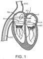
- Figure 1 illustrates a stage of a trans-septal approach for implanting a valve replacement device.
- access is via the inferior vena cava IVC or superior vena cava SVC, through the right atrium RA, across the inter-atrial septum IAS, and into the left atrium LA above the mitral valve MV.
- a catheter 1 having a needle 2 moves from the inferior vena cava IVC into the right atrium RA. Once the catheter 1 reaches the anterior side of the inter-atrial septum IAS, the needle 2 advances so that it penetrates through the septum, for example at the fossa ovalis FO or the foramen ovale into the left atrium LA.
- a guidewire replaces the needle 2 and the catheter 1 is withdrawn.
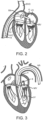
- Figure 2 illustrates a subsequent stage of a trans-septal approach in which guidewire 6 and guide catheter 4 pass through the inter-atrial septum IAS.
- the guide catheter 4 provides access to the mitral valve for implanting a valve replacement device in accordance with the technology.
- surgical access may be obtained through an intercostal incision, preferably without removing ribs, and a small puncture or incision may be made in the left atrial wall.
- a guide catheter passes through this puncture or incision directly into the left atrium, sealed by a purse string-suture.
- the antegrade or trans-septal approach to the mitral valve can be advantageous in many respects.
- antegrade approaches will usually enable more precise and effective centering and stabilization of the guide catheter and/or prosthetic valve device.
- the antegrade approach may also reduce the risk of damaging the chordae tendinae or other subvalvular structures with a catheter or other interventional tool.
- the antegrade approach may decrease risks associated with crossing the aortic valve as in retrograde approaches. This can be particularly relevant to patients with prosthetic aortic valves, which cannot be crossed at all or without substantial risk of damage.
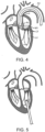
- FIGS 3 and 4 show examples of a retrograde approaches to access the mitral valve.
- Access to the mitral valve MV may be achieved from the aortic arch AA, across the aortic valve AV, and into the left ventricle LV below the mitral valve MV.
- the aortic arch AA may be accessed through a conventional femoral artery access route or through more direct approaches via the brachial artery, axillary artery, radial artery, or carotid artery. Such access may be achieved with the use of a guidewire 6. Once in place, a guide catheter 4 may be tracked over the guidewire 6.
- a surgical approach may be taken through an incision in the chest, preferably intercostally without removing ribs, and placing a guide catheter through a puncture in the aorta itself.
- the guide catheter 4 affords subsequent access to permit placement of the prosthetic valve device, as described in more detail herein.
- Retrograde approaches advantageously do not need a trans-septal puncture. Cardiologists also more commonly use retrograde approaches, and thus retrograde approaches are more familiar.
- FIG. 5 shows a trans-apical approach via a trans-apical puncture.
- access to the heart is via a thoracic incision, which can be a conventional open thoracotomy or sternotomy, or a smaller intercostal or sub-xyphoid incision or puncture.
- An access cannula is then placed through a puncture in the wall of the left ventricle at or near the apex of the heart.
- the catheters and prosthetic devices of the invention may then be introduced into the left ventricle through this access cannula.
- the trans-apical approach provides a shorter, straighter, and more direct path to the mitral or aortic valve. Further, because it does not involve intravascular access, the trans-apical approach does not require training in interventional cardiology to perform the catheterizations required in other percutaneous approaches.
- Embodiments of the present technology can treat one or more of the valves of the heart, and in particular several embodiments advantageously treat the mitral valve.
- the prosthetic valve devices of the present technology can also be suitable for replacement of other valves (e.g., a bicuspid or tricuspid valve) in the heart of the patient.
- Examples of prosthetic heart valve devices in accordance with embodiments of the present technology are described in this section with reference to Figures 6A-8B . Specific elements, substructures, advantages, uses, and/or other features of the embodiments described with reference to Figures 6A-8B can be suitably interchanged, substituted or otherwise configured with one another. Furthermore, suitable elements of the embodiments described with reference to Figures 6A-8B can be used as stand-alone and/or self-contained devices.
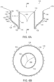
- FIG 6A is a side cross-sectional view and Figure 6B is a top plan view of a prosthetic heart valve device (“device") 100 in accordance with an embodiment of the present technology.
- the device 100 includes a valve support 110, an anchoring member 120 attached to the valve support 110, and a prosthetic valve assembly 150 within the valve support 110.
- the valve support 110 has an inflow region 112 and an outflow region 114.
- the prosthetic valve assembly 150 is arranged within the valve support 110 to allow blood to flow from the inflow region 112 through the outflow region 114 (arrows BF), but prevent blood from flowing in a direction from the outflow region 114 through the inflow region 112.
- the anchoring member 120 includes a base 122 attached to the outflow region 114 of the valve support 110 and a plurality of arms 124 projecting laterally outward from the base 122.
- the anchoring member 120 also includes a fixation structure 130 extending from the arms 124.
- the fixation structure 130 can include a first portion 132 and a second portion 134.
- the first portion 132 of the fixation structure 130 can be an upstream region of the fixation structure 130 that, in a deployed configuration as shown in Figure 6A , is spaced laterally outward apart from the inflow region 112 of the valve support 110 by a gap G.
- the second portion 134 of the fixation structure 130 can be a downstream-most portion of the fixation structure 130.
- the fixation structure 130 can be a cylindrical ring (e.g., straight cylinder or conical), and the outer surface of the fixation structure 130 can define an annular engagement surface configured to press outwardly against the native annulus.
- the fixation structure 130 can further include a plurality of fixation elements 136 that project radially outward and are inclined toward an upstream direction.
- the fixation elements 136 can be barbs, hooks, or other elements that are inclined only in the upstream direction (e.g., a direction extending away from the downstream portion of the device 100).
- the anchoring member 120 has a smooth bend 140 between the arms 124 and the fixation structure 130.
- the second portion 134 of the fixation structure 130 extends from the arms 124 at the smooth bend 140.
- the arms 124 and the fixation structure 130 can be formed integrally from a continuous strut or support element such that the smooth bend 140 is a bent portion of the continuous strut.
- the smooth bend 140 can be a separate component with respect to either the arms 124 or the fixation structure 130.
- the smooth bend 140 can be attached to the arms 124 and/or the fixation structure 130 using a weld, adhesive or other technique that forms a smooth connection.
- the smooth bend 140 is configured such that the device 100 can be recaptured in a capsule or other container after the device 100 has been at least partially deployed.
- the device 100 can further include a first sealing member 162 on the valve support 110 and a second sealing member 164 on the anchoring member 120.
- the first and second sealing members 162, 164 can be made from a flexible material, such as Dacron ® or another type of polymeric material.
- the first sealing member 162 can cover the interior and/or exterior surfaces of the valve support 110.
- the first sealing member 162 is attached to the interior surface of the valve support 110
- the prosthetic valve assembly 150 is attached to the first sealing member 162 and commissure portions of the valve support 110.
- the second sealing member 164 is attached to the inner surface of the anchoring member 120.
- the device 100 further includes an extension member 170.
- the extension member 170 can be an extension of the second sealing member 164, or it can be a separate component attached to the second sealing member 164 and/or the first portion 132 of the fixation structure 130.
- the extension member 170 can be a flexible member that, in a deployed state as shown in Figure 6A , flexes relative to the first portion 132 of the fixation structure 130. In operation, the extension member 170 guides the device 100 during implantation such that the device is located at a desired elevation and centered relative to the native annulus.
- one or more components of the extension member 170 can be made of or include a radiopaque material.
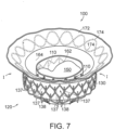
- Figure 7 is a top isometric view of an example of the device 100.
- the valve support 110 defines a first frame (e.g., an inner frame) and fixation structure 130 of the anchoring member 120 defines a second frame (e.g., an outer frame) that each include a plurality of structural elements.
- the fixation structure 130 more specifically, includes structural elements 137 arranged in diamond-shaped cells 138 that together form at least a substantially cylindrical ring when freely and fully expanded as shown in Figure 7 .
- the structural elements 137 can be struts or other structural features formed from metal, polymers, or other suitable materials that can self-expand or be expanded by a balloon or other type of mechanical expander.
- fixation structure 130 can be a generally cylindrical fixation ring having an outwardly facing engagement surface.
- the outer surfaces of the structural elements 137 define an annular engagement surface configured to press outwardly against the native annulus in the deployed state.
- the fixation structure 130 In a fully expanded state without any restrictions, the fixation structure 130 is at least substantially parallel to the valve support 110.
- the fixation structure 130 can flex inwardly (arrow I) in the deployed state when it presses radially outwardly against the inner surface of the native annulus of a heart valve.
- the embodiment of the device 100 shown in Figure 7 includes the first sealing member 162 lining the interior surface of the valve support 110, and the second sealing member 164 along the inner surface of the fixation structure 130.
- the extension member 170 has a flexible web 172 (e.g., a fabric) and a support member 174 (e.g., metal or polymeric strands) attached to the flexible web 172.
- the flexible web 172 can extend from the second sealing member 164 without a metal-to-metal connection between the fixation structure 130 and the support member 174.
- the extension member 170 can be a continuation of the material of the second sealing member 164.
- the support member 174 can have a variety of configurations and be made from a variety of materials, such as a double-serpentine structure made from Nitinol.
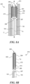
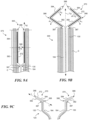
- Figures 8A-8D show one embodiment of a prosthetic heart valve device 200 ("the device 200") having an extension member 270 configured to fold or bend onto itself in the delivery configuration ( Figures 8A and 8B ) and unfurl to an extended configuration when deployed ( Figures 8C and 8D ).
- the collapsible extension member 270 reduces the total length of the device 200 in the delivery configuration without sacrificing the lateral coverage of the extension member 270 in the deployed or extended configuration (as compared to a similar device having a non-folded extension member in the delivery configuration).
- the reduced length of the device 200 improves the maneuverability of the catheter C when the device 200 is positioned within the catheter lumen, which is especially beneficial when navigating the tortuous intravascular and/or intracardiac path to the mitral valve annulus.
- Such improved maneuverability for example, can be particularly advantageous for making the sharp turn towards the mitral valve annulus after crossing the inter-atrial septum IAS during a trans-septal approach (discussed above with reference to Figures 1 and 2 ).
- the device 200 shown in Figures 8A-8D can include components that are generally similar in structure and function to those of the device 100 in Figures 6A-7 .
- the device 200 includes the valve support 110 (not shown for ease of illustration), the anchoring member 120 ( Figure 8D only), the prosthetic valve assembly 150 (not shown for ease of illustration), and preferably the second sealing member 164 (not shown for ease of illustration), all of which are generally similar to those discussed above with reference to Figures 6A-7 .
- common acts and structures and/or sub-structures are identified by the same reference numbers, and only significant differences in operation and structure are described below.
- Figure 8A shows a distal portion of the device 200 in a delivery configuration within a catheter C.
- the extension member 270 has a flexible web 272 and a support member 274 attached to the flexible web 272.
- the flexible web 272 is a continuation of the material of the second sealing member 164, and the support member 274 is spaced apart from the fixation structure 130 along the second sealing member 164.
- the flexible web 272 is not integral with the second sealing member 164 (e.g., the flexible web 272 is a separate piece of fabric), and/or the support member 274 is integral with the fixation structure 130.
- the support member 274 may be positioned at a surface of the web 272.
- the support member 274 may be positioned on an atrial surface 272a (see Figure 8D ) of the web 272, and in other embodiments the support member 274 may be positioned on a ventricular surface 272b (see Figure 8D ) of the web 272.
- Figure 8B is an enlarged, isolated view of a portion of the extension member 270 and fixation structure 130 shown in Figure 8A .
- the extension member 270 has a longitudinal axis L E , a first terminus 287 at the fixation structure 130, a free second terminus 288, and a length measured along the longitudinal axis L E ( Figure 8B ) between the first and second termini 287, 288.
- the extension member 270 also has a first portion 282 and a second portion 284 extending along its longitudinal axis L E ( Figure 8B ). The first portion 282 meets or is otherwise coupled to the second portion 284 at a joint 286.
- the first portion 282 has a length measured between the first terminus 287 of the extension member 270 and the joint 286, and the second portion 284 has a length measured between the joint 286 and the second terminus 288 of the extension member 270.
- the support member 274 extends along the longitudinal axis L E from a first location along the first portion 282 to a second location along the second portion 284. As discussed in greater detail below, the support member 274 is configured to preferentially bend at the joint 286 of the extension member 270. In certain embodiments, the support member 274 extends only a portion of the length of the extension member 270, and in some embodiments the support member 274 extends the entire length of the extension member 270.
- the support member 274 can have a variety of configurations and be made from a variety of materials.
- the extension member 270 When positioned in the delivery configuration within the catheter C (e.g., Figure 8A ), the extension member 270 may be folded back on itself such that at least a portion of the first portion 282 overlaps at least a portion of the second portion 284 and the extension member 270 includes a folded or bent edge at the joint 286.
- the first portion 282 extends distally from the fixation structure 130 and/or first terminus 287 to the joint 286, and the second portion 284 extends proximally from the joint 286 to the second terminus 288.
- the extension member 270 may be folded or configured to fold at a single location along the longitudinal axis of the support member 274 and/or extension member 270, thereby dividing the extension member 270 into the first and second portions 282, 284.
- the extension member 270 may be folded and/or configured to fold or bend at multiple locations along the longitudinal axis of the support member 274 and/or extension member 270 (e.g., like an accordion), thereby dividing the extension member 270 into more than two portions.
- the second portion 284 is shown positioned radially inward of the first portion 282 in Figures 8A and 8B , in other embodiments the second portion 284 can be positioned radially outward of the first portion 282 in the delivery configuration.
- the length of the first portion 282 is greater than the length of the second portion 284 such that the free second terminus 288 is distal of the first terminus 287 along the longitudinal axis L D ( Figure 8A ) of the device 200 when the device 200 is in the delivery configuration.
- the length of the first portion 282 is substantially the same as the length of the second portion 284 such that the free second terminus 288 is adjacent or aligned with the first terminus 287 along the longitudinal axis L D of the device 200 when the device 200 is in the delivery configuration.
- the length of the first portion 282 can be less than the length of the second portion 284 such that the second terminus 288 is proximal of the first terminus 287 along the longitudinal axis L D of the device 200 when the device 200 is in the delivery configuration.
- Figure 8C is a cross-sectional view of the extension member 270 as it releases from a distal end of the delivery catheter C and transforms from the delivery configuration to a deployed or extended configuration.
- Figure 8D is a cross-sectional, isolated view of the anchoring member 120, second sealing member 164, and extension member 270 when the device 200 is in a deployed configuration.
- the first portion 282 rotates radially away from a central longitudinal axis L D of the device 200 (indicated by arrows A 1 in Figure 8C ) around the first terminus 287, while the second portion 284 rotates radially away from the longitudinal axis L D around the joint 286 (indicated by arrows A 2 in Figure 8C ) until the longitudinal axis's of the first and second portions 282, 284 are generally aligned (e.g., the first and second portions 282, 284 are generally within the same plane along their lengths) unless otherwise constrained by the anatomy.
- the extension member 270 may be configured such that the second portion 284 is positioned at an angle with respect to the first portion 282 when the device 200 is in the deployed configuration.
- the distance between the first terminus 287 and the second terminus 288 of the extension member 270 is less when the extension member 270 is in the delivery configuration than when the extension member 270 is in the deployed configuration, thereby improving the maneuverability of the delivery system without sacrificing the lateral coverage of the extension member 270 in the deployed or extended configuration.
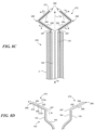
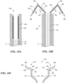
- Figures 9A-9C show another embodiment of a prosthetic heart valve device 300 ("the device 300") having an extension member 370 configured to fold or bend onto itself in the deployed configuration ( Figure 9C ).
- the device 300 shown in Figures 9A-9C can include components that are generally similar in structure and function to those of the device 100 in Figures 6A-7 .
- the device 300 includes the valve support 110 (not shown for ease of illustration), the anchoring member 120 ( Figure 9C only), the prosthetic valve assembly 150 (not shown for ease of illustration), and preferably the second sealing member 164 (not shown for ease of illustration), all of which are generally similar to those discussed above with reference to Figures 6A-7 .
- common acts and structures and/or sub-structures are identified by the same reference numbers, and only significant differences in operation and structure are described below.
- Figure 9A shows a distal portion of the device 300 in a delivery configuration within a catheter C.
- the extension member 370 has a flexible web 372 and a support member 374 attached to the flexible web 372.
- the flexible web 372 is a continuation of the material of the second sealing member 164, and the support member 374 is spaced apart from the fixation structure 130 along the second sealing member 164.
- the flexible web 372 is not integral with the second sealing member 164 (e.g., the flexible web 372 is a separate piece of material), and/or the support member 374 is integral with the fixation structure 130.
- the support member 374 may be positioned at a surface of the web 372.
- the extension member 370 has a first terminus 387 at the fixation structure 130, a free second terminus 388, and a length measured along its longitudinal axis L E between the first and second termini 387, 388.
- the extension member 370 also has a first portion 382 and a second portion 384 extending along its longitudinal axis L E .
- the first portion 382 meets or is otherwise coupled to the second portion 384 at a joint 386.
- the first portion 382 has a length measured between the first terminus 387 of the extension member 370 and the joint 386
- the second portion 384 has a length measured between the joint 386 and the second terminus 388 of the extension member 370.
- the support member 374 extends along the longitudinal axis L E of the extension member 370 from a first location along the first portion 382 to a second location along the second portion 384, and the support member 374 is configured to preferentially bend at the joint 386 of the extension member 370, as discussed in greater detail below. In certain embodiments the support member 374 extends only a portion of the length of the extension member 370, but in other embodiments the support member 374 extends the entire length of the extension member 370.
- the support member 374 can have a variety of configurations and be made from a variety of materials.
- the extension member 370 in the delivery configuration, can be generally straight such that the first portion 382 extends distally from the fixation structure 130, and the second portion 384 extends distally from the joint 386.
- the free second terminus 388 is spaced apart from the first terminus 387 by a distance measured along a longitudinal axis L E of the extension member 370 that is at least the combined lengths of the first portion 382 and the second portion 384.
- the joint 386 of extension member 370 provides an articulation and/or flexing point that improves the flexibility of the distal portion of the delivery system (i.e., delivery catheter C and device 300 loaded therein), at least as compared to an extension member that does not include a joint along its length.
- the joint 386 improves the maneuverability of the catheter C when the device 200 is positioned within the catheter lumen, which is especially beneficial when navigating the tortuous intravascular and/or intracardiac path to the mitral valve annulus, as discussed above with reference to Figures 8A-D .
- the joint 386 additionally improves the flexibility of the extension member 370 when the device 300 is positioned at the annulus, thereby allowing the device 300 to better adapt and conform to the local anatomy.
- Figure 9B is a cross-sectional view of the extension member 370 as it releases from a distal end of the delivery catheter C and transforms from the delivery configuration to a deployed or folded configuration
- Figure 9C is a cross-sectional, isolated view of the anchoring member 120, second sealing member 164, and extension member 370 when the device 300 is in a deployed configuration.
- the extension member 370 when the extension member 370 is released from a distal end of the delivery catheter C, the extension member 370 folds back on itself such that the first portion 382 rotates radially away from the central longitudinal axis L D of the device 300 (indicated by arrows A 1 in Figure 9B ) about the first terminus 387, and the second portion 384 rotates radially toward the central longitudinal axis L D (indicated by arrows As in Figure 9B ) about the joint 386.
- the second portion 384 overlaps at least a portion of the first portion 382 and the joint 386 therebetween forms a folded or bent edge.
- the second portion 384 rotates towards the fixation structure 130 in an upstream direction (indicated by arrows As in Figure 9B ) such that the second portion 384 is positioned upstream of the first portion 382 in the expanded configuration.
- the second portion 384 rotates towards the fixation structure 130 in a downstream direction (indicated by arrows A 4 in Figure 10B ) such that the second portion 384 is positioned downstream of the first portion 382 in the expanded configuration.
- the extension member 370 is folded or configured to fold at a single location along the longitudinal axis of the support member 374, thereby dividing the extension member 370 into the first and second portions 382, 384.
- the extension member 370 may be folded and/or configured to fold or bend at multiple locations along the longitudinal axis of the support member 374 (e.g., like an accordion), thereby dividing the extension member 370 into more than two portions.
- the length of the first portion 382 is substantially the same as the length of the second portion 384 such that the second free terminus 388 is adjacent or aligned with the first terminus 387 along a line L ( Figure 9C ) substantially parallel to the longitudinal axis of the first portion 382 when the device 300 is expanded.
- the distance between the second terminus 388 and the first terminus 387 along the line L is substantially zero.
- the length of the first portion 382 can be greater than the length of the second portion 384 such that the second terminus 388 is radially outward of and spaced apart from the first terminus 387 along the line L when the device 300 is expanded.
- the length of the first portion 382 can be less than the length of the second portion 384 such that the second terminus 388 is radially inward of and spaced apart from the first terminus 387 along the line L when the device 300 is expanded.
- the extension member may include one or more impedance sensors for detecting or otherwise assessing contact between the extension member and adjacent tissue (e.g., the leaflets, the atrial floor, etc.) while the prosthetic heart valve device is being positioned within the mitral annulus.
- the support member may be formed of a metal wire coated or otherwise surrounded by an insulative material.
- the support member can include one or more impedance sensors comprising portions of the metal wire exposed through corresponding openings in the insulative material.
- the wire may be electrically coupled to a conductive member that extends proximally from the prosthetic heart valve device to a proximal portion (e.g., a handle) of the delivery system.
- the metal wire may be directly coupled to the conductive member (i.e., in direct contact), and in other embodiments the metal wire may be indirectly coupled to the conductive member via the anchoring member and/or another conductive component of the device.
Description
- The present application claims priority to
U.S. Patent Application No. 15/643,011, filed July 6, 2017 - The present application refers to the subject matter of (1) International Patent Application No.
PCT/US2014/029549, filed March 14, 2014 , (2) International Patent Application No.PCT/US2012/061219, filed October 19, 2012 , (3) International Patent Application No.PCT/US2012/061215, filed October 19, 2012 , (4) International Patent Application No.PCT/US2012/043636, filed June 21, 2012 . The present application also refers to the subject matter ofU.S. Application No. 15/642,834 (Attorney Docket No. C00013623.USU1), filed concurrently herewith, andU.S. Application No. 15/642,834 (Attorney Docket No. C00013493.USU2), also filed concurrently herewith. - The present technology relates generally to prosthetic heart valve devices. In particular, several embodiments are directed to prosthetic mitral valves and devices for percutaneous repair and/or replacement of native mitral valves and associated systems.
- Heart valves can be affected by several conditions. For example, mitral valves can be affected by mitral valve regurgitation, mitral valve prolapse and mitral valve stenosis. Mitral valve regurgitation is abnormal leaking of blood from the left ventricle into the left atrium caused by a disorder of the heart in which the leaflets of the mitral valve fail to coapt into apposition at peak contraction pressures. The mitral valve leaflets may not coapt sufficiently because heart diseases often cause dilation of the heart muscle, which in turn enlarges the native mitral valve annulus to the extent that the leaflets do not coapt during systole. Abnormal backflow can also occur when the papillary muscles are functionally compromised due to ischemia or other conditions. More specifically, as the left ventricle contracts during systole, the affected papillary muscles do not contract sufficiently to effect proper closure of the leaflets.
- Mitral valve prolapse is a condition when the mitral leaflets bulge abnormally up in to the left atrium. This can cause irregular behavior of the mitral valve and lead to mitral valve regurgitation. The leaflets may prolapse and fail to coapt because the tendons connecting the papillary muscles to the inferior side of the mitral valve leaflets (chordae tendineae) may tear or stretch. Mitral valve stenosis is a narrowing of the mitral valve orifice that impedes filling of the left ventricle in diastole.
- Mitral valve regurgitation is often treated using diuretics and/or vasodilators to reduce the amount of blood flowing back into the left atrium. Surgical approaches (open and intravascular) for either the repair or replacement of the valve have also been used to treat mitral valve regurgitation. For example, typical repair techniques involve cinching or resecting portions of the dilated annulus. Cinching, for example, includes implanting annular or peri-annular rings that are generally secured to the annulus or surrounding tissue. Other repair procedures suture or clip the valve leaflets into partial apposition with one another.
- Alternatively, more invasive procedures replace the entire valve itself by implanting mechanical valves or biological tissue into the heart in place of the native mitral valve. These invasive procedures conventionally require large open thoracotomies and are thus very painful, have significant morbidity, and require long recovery periods. Moreover, with many repair and replacement procedures, the durability of the devices or improper sizing of annuloplasty rings or replacement valves may cause additional problems for the patient. Repair procedures also require a highly skilled cardiac surgeon because poorly or inaccurately placed sutures may affect the success of procedures.
- Less invasive approaches to aortic valve replacement have been implemented in recent years. Examples of pre-assembled, percutaneous prosthetic valves include, e.g., the CoreValve Revalving® System from Medtronic/Corevalve Inc. (Irvine, CA, USA) and the Edwards-Sapien® Valve from Edwards Lifesciences (Irvine, CA, USA). Both valve systems include an expandable frame and a tri-leaflet bioprosthetic valve attached to the expandable frame. The aortic valve is substantially symmetric, circular, and has a muscular annulus. The expandable frames in aortic applications have a symmetric, circular shape at the aortic valve annulus to match the native anatomy, but also because tri-leaflet prosthetic valves require circular symmetry for proper coaptation of the prosthetic leaflets. Thus, aortic valve anatomy lends itself to an expandable frame housing a replacement valve since the aortic valve anatomy is substantially uniform, symmetric, and fairly muscular. Other heart valve anatomies, however, are not uniform, symmetric or sufficiently muscular, and thus transvascular aortic valve replacement devises may not be well suited for other types of heart valves.
- The triscuspid valve on the right side of the heart, although it normally has three leaflets, poses similar challenges to less invasive treatment as the mitral valve. Therefore there is a need for a better prosthesis to treat tricuspid valve disease as well.
- Given the difficulties associated with current procedures, there remains the need for simple, effective, and less invasive devices and methods for treating dysfunctional heart valves.
EP 2 695 586 A1WO2014/144937A2 , discloses a valve prosthesis. - Many aspects of the present disclosure can be better understood with reference to the following drawings. The components in the drawings are not necessarily to scale, and instead emphasis is placed on illustrating clearly the principles of the present disclosure. Furthermore, components can be shown as transparent in certain views for clarity of illustration only and not to indicate that the illustrated component is necessarily transparent. For ease of reference, throughout this disclosure identical reference numbers and/or letters are used to identify similar or analogous components or features, but the use of the same reference number does not imply that the parts should be construed to be identical. Indeed, in many examples described herein, identically numbered components refer to different embodiments that are distinct in structure and/or function. The headings provided herein are for convenience only. The claimed inventions are defined in
independent claims 1 and 9. Further aspects and preferred embodiments are defined in the dependent claims. -
Figure 1 is a schematic, cross-sectional illustration of the heart showing an antegrade approach to the native mitral valve from the venous vasculature in accordance with various embodiments of the present technology. -
Figure 2 is a schematic, cross-sectional illustration of the heart showing access through the inter-atrial septum (IAS) maintained by the placement of a guide catheter over a guidewire in accordance with various embodiments of the present technology. -
Figures 3 and4 are schematic, cross-sectional illustrations of the heart showing retrograde approaches to the native mitral valve through the aortic valve and arterial vasculature in accordance with various embodiments of the present technology. -
Figure 5 is a schematic, cross-sectional illustration of the heart showing an approach to the native mitral valve using a trans-apical puncture in accordance with various embodiments of the present technology. -
Figure 6A is a cross-sectional side view andFigure 6B is a top view schematically illustrating a prosthetic heart valve device in accordance with an embodiment of the present technology. -
Figure 7 is a top isometric view of a prosthetic heart valve device in accordance with an embodiment of the present technology, shown in a deployed configuration. -
Figure 8A is a schematic cross-sectional view of a portion of a prosthetic heart valve device in accordance with an embodiment of the present technology, shown in a delivery configuration within a delivery catheter. -
Figure 8B is an enlarged view of a portion of the extension member shown inFigure 8A . -
Figure 8C is a cross-sectional view of the portion of the prosthetic heart valve device ofFigure 8A , shown as the extension member is being released from the distal end of the delivery catheter and transforming from the delivery configuration to a deployed configuration. -
Figure 8D is a cross-sectional view of the prosthetic heart valve device ofFigure 8A , shown in a deployed configuration. -
Figure 9A is a schematic cross-sectional view of a portion of a prosthetic heart valve device shown in a delivery configuration within a delivery catheter in accordance with an embodiment of the present technology. -
Figure 9B is a cross-sectional view of the portion of the prosthetic heart valve device ofFigure 9A showing the extension member as it releases from the distal end of the delivery catheter and transforms from the delivery configuration to a deployed configuration. -
Figure 9C is a cross-sectional view of the prosthetic heart valve device ofFigure 9A , shown in a deployed configuration. -
Figure 10A is a schematic cross-sectional view of a portion of a prosthetic heart valve device shown in a delivery configuration within a delivery catheter in accordance with an embodiment of the present technology. -
Figure 10B is a cross-sectional view of a portion of a prosthetic heart valve device in accordance with an embodiment of the present technology showing the extension member as it releases from the distal end of the delivery catheter and transforms from the delivery configuration to a deployed configuration. -
Figure 10C is a cross-sectional view of the prosthetic heart valve device ofFigure 10A , shown in a deployed configuration. - Specific details of several embodiments of the technology are described below with reference to
Figures 1-10C . Although many of the embodiments are described below with respect to prosthetic valve devices, systems, and methods for percutaneous replacement of a native mitral valve, other applications and other embodiments in addition to those described herein are within the scope of the technology. Additionally, several other embodiments of the technology can have different configurations, components, or procedures than those described herein. A person of ordinary skill in the art, therefore, will accordingly understand that the technology can have other embodiments with additional elements, or the technology can have other embodiments without several of the features shown and described below with reference toFigures 1-10C . - With regard to the terms "distal" and "proximal" within this description, unless otherwise specified, the terms can reference a relative position of the portions of a prosthetic valve device and/or an associated delivery device with reference to an operator and/or a location in the vasculature or heart. For example, in referring to a delivery catheter suitable to deliver and position various prosthetic valve devices described herein, "proximal" can refer to a position closer to the operator of the device or an incision into the vasculature, and "distal" can refer to a position that is more distant from the operator of the device or further from the incision along the vasculature (e.g., the end of the catheter). With respect to a prosthetic heart valve device, the terms "proximal" and "distal" can refer to the location of portions of the device with respect to the direction of blood flow. For example, proximal can refer to an upstream position or a location where blood flows into the device (e.g., inflow region), and distal can refer to a downstream position or a location where blood flows out of the device (e.g., outflow region).
- Several embodiments of the present technology are directed to mitral valve replacement devices that address the unique challenges of percutaneously replacing native mitral valves and are well-suited for navigating through the heart anatomy to the mitral valve annulus. Compared to replacing aortic valves, percutaneous mitral valve replacement faces unique anatomical obstacles that render percutaneous mitral valve replacement significantly more challenging than aortic valve replacement. First, unlike relatively symmetric and uniform aortic valves, the mitral valve annulus has a non-circular D-shape or kidney-like shape, with a non-planar, saddle-like geometry often lacking symmetry. The complex and highly variable anatomy of mitral valves makes it difficult to design a mitral valve prosthesis that conforms well to the native mitral annulus of specific patients. As a result, the prosthesis may not fit well with the native leaflets and/or annulus, which can leave gaps that allows backflow of blood to occur. For example, placement of a cylindrical valve prosthesis in a native mitral valve may leave gaps in commissural regions of the native valve through which perivalvular leaks may occur.
- Current prosthetic valves developed for percutaneous aortic valve replacement are unsuitable for use in mitral valves. First, many of these devices require a direct, structural connection between the stent-like structure that contacts the annulus and/or leaflets and the prosthetic valve. In several devices, the stent posts which support the prosthetic valve also contact the annulus or other surrounding tissue. These types of devices directly transfer the forces exerted by the tissue and blood as the heart contracts to the valve support and the prosthetic leaflets, which in turn distorts the valve support from its desired cylindrical shape. This is a concern because most cardiac replacement devices use tri-leaflet valves, which require a substantially symmetric, cylindrical support around the prosthetic valve for proper opening and closing of the three leaflets over years of life. As a result, when these devices are subject to movement and forces from the annulus and other surrounding tissues, the prostheses may be compressed and/or distorted causing the prosthetic leaflets to malfunction. Moreover, a diseased mitral annulus is much larger than any available prosthetic aortic valve. As the size of the valve increases, the forces on the valve leaflets increase dramatically, so simply increasing the size of an aortic prosthesis to the size of a dilated mitral valve annulus would require dramatically thicker, taller leaflets, and might not be feasible.
- In addition to its irregular, complex shape, which changes size over the course of each heartbeat, the mitral valve annulus lacks a significant amount of radial support from surrounding tissue. Compared to aortic valves, which are completely surrounded by fibro-elastic tissue that provides sufficient support for anchoring a prosthetic valve, mitral valves are bound by muscular tissue on the outer wall only. The inner wall of the mitral valve anatomy is bound by a thin vessel wall separating the mitral valve annulus from the inferior portion of the aortic outflow tract. As a result, significant radial forces on the mitral annulus, such as those imparted by an expanding stent prostheses, could lead to collapse of the inferior portion of the aortic tract. Moreover, larger prostheses exert more force and expand to larger dimensions, which exacerbates this problem for mitral valve replacement applications.
- The chordae tendineae of the left ventricle may also present an obstacle in deploying a mitral valve prosthesis. Unlike aortic valves, mitral valves have a maze of cordage under the leaflets in the left ventricle that restrict the movement and position of a deployment catheter and the replacement device during implantation. As a result, deploying, positioning and anchoring a valve replacement device on the ventricular side of the native mitral valve annulus is complicated.
- Embodiments of the present technology provide systems, methods and apparatus to treat heart valves of the body, such as the mitral valve, that address the challenges associated with the anatomy of the mitral valve and provide for improved maneuverability of the device when positioned within the delivery catheter. The apparatus and methods enable a percutaneous approach using a catheter delivered intravascularly through a vein or artery into the heart, or through a cannula inserted through the heart wall. For example, the apparatus and methods are particularly well-suited for trans-septal approaches, but can also be trans-apical, trans-atrial, and direct aortic delivery of a prosthetic replacement valve to a target location in the heart. Additionally, the embodiments of the devices and methods as described herein can be combined with many known surgeries and procedures, such as known methods of accessing the valves of the heart (e.g., the mitral valve or triscuspid valve) with antegrade or retrograde approaches, and combinations thereof.
- To better understand the structure and operation of valve replacement devices in accordance with the present technology, it is helpful to first understand approaches for implanting the devices. The mitral valve or other type of atrioventricular valve can be accessed through the patient's vasculature in a percutaneous manner. By percutaneous it is meant that a location of the vasculature remote from the heart is accessed through the skin, typically using a surgical cut down procedure or a minimally invasive procedure, such as using needle access through, for example, the Seldinger technique. The ability to percutaneously access the remote vasculature is well known and described in the patent and medical literature. Depending on the point of vascular access, access to the mitral valve may be antegrade and may rely on entry into the left atrium by crossing the inter-atrial septum (e.g., a trans-septal approach). Alternatively, access to the mitral valve can be retrograde where the left ventricle is entered through the aortic valve. Access to the mitral valve may also be achieved using a cannula via a trans-apical approach. Depending on the approach, the interventional tools and supporting catheter(s) may be advanced to the heart intravascularly and positioned adjacent the target cardiac valve in a variety of manners, as described herein.
-
Figure 1 illustrates a stage of a trans-septal approach for implanting a valve replacement device. In a trans-septal approach, access is via the inferior vena cava IVC or superior vena cava SVC, through the right atrium RA, across the inter-atrial septum IAS, and into the left atrium LA above the mitral valve MV. As shown inFigure 1 , acatheter 1 having aneedle 2 moves from the inferior vena cava IVC into the right atrium RA. Once thecatheter 1 reaches the anterior side of the inter-atrial septum IAS, theneedle 2 advances so that it penetrates through the septum, for example at the fossa ovalis FO or the foramen ovale into the left atrium LA. At this point, a guidewire replaces theneedle 2 and thecatheter 1 is withdrawn. -
Figure 2 illustrates a subsequent stage of a trans-septal approach in which guidewire 6 and guidecatheter 4 pass through the inter-atrial septum IAS. Theguide catheter 4 provides access to the mitral valve for implanting a valve replacement device in accordance with the technology. - In an alternative antegrade approach (not shown), surgical access may be obtained through an intercostal incision, preferably without removing ribs, and a small puncture or incision may be made in the left atrial wall. A guide catheter passes through this puncture or incision directly into the left atrium, sealed by a purse string-suture.
- The antegrade or trans-septal approach to the mitral valve, as described above, can be advantageous in many respects. For example, antegrade approaches will usually enable more precise and effective centering and stabilization of the guide catheter and/or prosthetic valve device. The antegrade approach may also reduce the risk of damaging the chordae tendinae or other subvalvular structures with a catheter or other interventional tool. Additionally, the antegrade approach may decrease risks associated with crossing the aortic valve as in retrograde approaches. This can be particularly relevant to patients with prosthetic aortic valves, which cannot be crossed at all or without substantial risk of damage.
-
Figures 3 and4 show examples of a retrograde approaches to access the mitral valve. Access to the mitral valve MV may be achieved from the aortic arch AA, across the aortic valve AV, and into the left ventricle LV below the mitral valve MV. The aortic arch AA may be accessed through a conventional femoral artery access route or through more direct approaches via the brachial artery, axillary artery, radial artery, or carotid artery. Such access may be achieved with the use of a guidewire 6. Once in place, aguide catheter 4 may be tracked over the guidewire 6. Alternatively, a surgical approach may be taken through an incision in the chest, preferably intercostally without removing ribs, and placing a guide catheter through a puncture in the aorta itself. Theguide catheter 4 affords subsequent access to permit placement of the prosthetic valve device, as described in more detail herein. Retrograde approaches advantageously do not need a trans-septal puncture. Cardiologists also more commonly use retrograde approaches, and thus retrograde approaches are more familiar. -
Figure 5 shows a trans-apical approach via a trans-apical puncture. In this approach, access to the heart is via a thoracic incision, which can be a conventional open thoracotomy or sternotomy, or a smaller intercostal or sub-xyphoid incision or puncture. An access cannula is then placed through a puncture in the wall of the left ventricle at or near the apex of the heart. The catheters and prosthetic devices of the invention may then be introduced into the left ventricle through this access cannula. The trans-apical approach provides a shorter, straighter, and more direct path to the mitral or aortic valve. Further, because it does not involve intravascular access, the trans-apical approach does not require training in interventional cardiology to perform the catheterizations required in other percutaneous approaches. - Embodiments of the present technology can treat one or more of the valves of the heart, and in particular several embodiments advantageously treat the mitral valve. The prosthetic valve devices of the present technology can also be suitable for replacement of other valves (e.g., a bicuspid or tricuspid valve) in the heart of the patient. Examples of prosthetic heart valve devices in accordance with embodiments of the present technology are described in this section with reference to
Figures 6A-8B . Specific elements, substructures, advantages, uses, and/or other features of the embodiments described with reference toFigures 6A-8B can be suitably interchanged, substituted or otherwise configured with one another. Furthermore, suitable elements of the embodiments described with reference toFigures 6A-8B can be used as stand-alone and/or self-contained devices. -
Figure 6A is a side cross-sectional view andFigure 6B is a top plan view of a prosthetic heart valve device ("device") 100 in accordance with an embodiment of the present technology. Thedevice 100 includes avalve support 110, an anchoringmember 120 attached to thevalve support 110, and aprosthetic valve assembly 150 within thevalve support 110. Referring toFigure 6A , thevalve support 110 has aninflow region 112 and anoutflow region 114. Theprosthetic valve assembly 150 is arranged within thevalve support 110 to allow blood to flow from theinflow region 112 through the outflow region 114 (arrows BF), but prevent blood from flowing in a direction from theoutflow region 114 through theinflow region 112. - In the embodiment shown in
Figure 6A , the anchoringmember 120 includes a base 122 attached to theoutflow region 114 of thevalve support 110 and a plurality ofarms 124 projecting laterally outward from thebase 122. The anchoringmember 120 also includes afixation structure 130 extending from thearms 124. Thefixation structure 130 can include afirst portion 132 and asecond portion 134. Thefirst portion 132 of thefixation structure 130, for example, can be an upstream region of thefixation structure 130 that, in a deployed configuration as shown inFigure 6A , is spaced laterally outward apart from theinflow region 112 of thevalve support 110 by a gap G. Thesecond portion 134 of thefixation structure 130 can be a downstream-most portion of thefixation structure 130. Thefixation structure 130 can be a cylindrical ring (e.g., straight cylinder or conical), and the outer surface of thefixation structure 130 can define an annular engagement surface configured to press outwardly against the native annulus. Thefixation structure 130 can further include a plurality offixation elements 136 that project radially outward and are inclined toward an upstream direction. Thefixation elements 136, for example, can be barbs, hooks, or other elements that are inclined only in the upstream direction (e.g., a direction extending away from the downstream portion of the device 100). - Referring still to
Figure 6A , the anchoringmember 120 has asmooth bend 140 between thearms 124 and thefixation structure 130. For example, thesecond portion 134 of thefixation structure 130 extends from thearms 124 at thesmooth bend 140. Thearms 124 and thefixation structure 130 can be formed integrally from a continuous strut or support element such that thesmooth bend 140 is a bent portion of the continuous strut. In other embodiments, thesmooth bend 140 can be a separate component with respect to either thearms 124 or thefixation structure 130. For example, thesmooth bend 140 can be attached to thearms 124 and/or thefixation structure 130 using a weld, adhesive or other technique that forms a smooth connection. Thesmooth bend 140 is configured such that thedevice 100 can be recaptured in a capsule or other container after thedevice 100 has been at least partially deployed. - The
device 100 can further include afirst sealing member 162 on thevalve support 110 and asecond sealing member 164 on the anchoringmember 120. The first andsecond sealing members first sealing member 162 can cover the interior and/or exterior surfaces of thevalve support 110. In the embodiment illustrated inFigure 6A , thefirst sealing member 162 is attached to the interior surface of thevalve support 110, and theprosthetic valve assembly 150 is attached to thefirst sealing member 162 and commissure portions of thevalve support 110. Thesecond sealing member 164 is attached to the inner surface of the anchoringmember 120. As a result, the outer annular engagement surface of thefixation structure 130 is not covered by thesecond sealing member 164 so that the outer annular engagement surface of thefixation structure 130 directly contacts the tissue of the native annulus. - The
device 100 further includes anextension member 170. Theextension member 170 can be an extension of thesecond sealing member 164, or it can be a separate component attached to thesecond sealing member 164 and/or thefirst portion 132 of thefixation structure 130. Theextension member 170 can be a flexible member that, in a deployed state as shown inFigure 6A , flexes relative to thefirst portion 132 of thefixation structure 130. In operation, theextension member 170 guides thedevice 100 during implantation such that the device is located at a desired elevation and centered relative to the native annulus. In some embodiments, one or more components of theextension member 170 can be made of or include a radiopaque material. -
Figure 7 is a top isometric view of an example of thedevice 100. In this embodiment, thevalve support 110 defines a first frame (e.g., an inner frame) andfixation structure 130 of the anchoringmember 120 defines a second frame (e.g., an outer frame) that each include a plurality of structural elements. Thefixation structure 130, more specifically, includesstructural elements 137 arranged in diamond-shapedcells 138 that together form at least a substantially cylindrical ring when freely and fully expanded as shown inFigure 7 . Thestructural elements 137 can be struts or other structural features formed from metal, polymers, or other suitable materials that can self-expand or be expanded by a balloon or other type of mechanical expander. - Several embodiments of the
fixation structure 130 can be a generally cylindrical fixation ring having an outwardly facing engagement surface. For example, in the embodiment shown inFigure 7 , the outer surfaces of thestructural elements 137 define an annular engagement surface configured to press outwardly against the native annulus in the deployed state. In a fully expanded state without any restrictions, thefixation structure 130 is at least substantially parallel to thevalve support 110. However, thefixation structure 130 can flex inwardly (arrow I) in the deployed state when it presses radially outwardly against the inner surface of the native annulus of a heart valve. - The embodiment of the
device 100 shown inFigure 7 includes thefirst sealing member 162 lining the interior surface of thevalve support 110, and thesecond sealing member 164 along the inner surface of thefixation structure 130. Theextension member 170 has a flexible web 172 (e.g., a fabric) and a support member 174 (e.g., metal or polymeric strands) attached to theflexible web 172. Theflexible web 172 can extend from thesecond sealing member 164 without a metal-to-metal connection between thefixation structure 130 and thesupport member 174. For example, theextension member 170 can be a continuation of the material of thesecond sealing member 164. Several embodiments of theextension member 170 are thus a floppy structure that can readily flex with respect to thefixation structure 130. Thesupport member 174 can have a variety of configurations and be made from a variety of materials, such as a double-serpentine structure made from Nitinol. -
Figures 8A-8D show one embodiment of a prosthetic heart valve device 200 ("thedevice 200") having anextension member 270 configured to fold or bend onto itself in the delivery configuration (Figures 8A and 8B ) and unfurl to an extended configuration when deployed (Figures 8C and 8D ). As such, thecollapsible extension member 270 reduces the total length of thedevice 200 in the delivery configuration without sacrificing the lateral coverage of theextension member 270 in the deployed or extended configuration (as compared to a similar device having a non-folded extension member in the delivery configuration). The reduced length of thedevice 200 improves the maneuverability of the catheter C when thedevice 200 is positioned within the catheter lumen, which is especially beneficial when navigating the tortuous intravascular and/or intracardiac path to the mitral valve annulus. Such improved maneuverability, for example, can be particularly advantageous for making the sharp turn towards the mitral valve annulus after crossing the inter-atrial septum IAS during a trans-septal approach (discussed above with reference toFigures 1 and2 ). - The
device 200 shown inFigures 8A-8D can include components that are generally similar in structure and function to those of thedevice 100 inFigures 6A-7 . For example, thedevice 200 includes the valve support 110 (not shown for ease of illustration), the anchoring member 120 (Figure 8D only), the prosthetic valve assembly 150 (not shown for ease of illustration), and preferably the second sealing member 164 (not shown for ease of illustration), all of which are generally similar to those discussed above with reference toFigures 6A-7 . As such, common acts and structures and/or sub-structures are identified by the same reference numbers, and only significant differences in operation and structure are described below. -
Figure 8A shows a distal portion of thedevice 200 in a delivery configuration within a catheter C. Theextension member 270 has aflexible web 272 and asupport member 274 attached to theflexible web 272. In the embodiment shown inFigures 8A-8D , theflexible web 272 is a continuation of the material of thesecond sealing member 164, and thesupport member 274 is spaced apart from thefixation structure 130 along thesecond sealing member 164. In other embodiments, theflexible web 272 is not integral with the second sealing member 164 (e.g., theflexible web 272 is a separate piece of fabric), and/or thesupport member 274 is integral with thefixation structure 130. Moreover, although the embodiment shown inFigure 8A shows thesupport member 274 disposed at an interior region of the flexible web 272 (e.g., between two layers of fabric), in other embodiments thesupport member 274 may be positioned at a surface of theweb 272. For example, in some embodiments thesupport member 274 may be positioned on anatrial surface 272a (seeFigure 8D ) of theweb 272, and in other embodiments thesupport member 274 may be positioned on aventricular surface 272b (seeFigure 8D ) of theweb 272. -
Figure 8B is an enlarged, isolated view of a portion of theextension member 270 andfixation structure 130 shown inFigure 8A . Referring toFigures 8A and 8B together, theextension member 270 has a longitudinal axis LE, afirst terminus 287 at thefixation structure 130, a freesecond terminus 288, and a length measured along the longitudinal axis LE (Figure 8B ) between the first andsecond termini extension member 270 also has afirst portion 282 and asecond portion 284 extending along its longitudinal axis LE (Figure 8B ). Thefirst portion 282 meets or is otherwise coupled to thesecond portion 284 at a joint 286. Thefirst portion 282 has a length measured between thefirst terminus 287 of theextension member 270 and the joint 286, and thesecond portion 284 has a length measured between the joint 286 and thesecond terminus 288 of theextension member 270. Thesupport member 274 extends along the longitudinal axis LE from a first location along thefirst portion 282 to a second location along thesecond portion 284. As discussed in greater detail below, thesupport member 274 is configured to preferentially bend at the joint 286 of theextension member 270. In certain embodiments, thesupport member 274 extends only a portion of the length of theextension member 270, and in some embodiments thesupport member 274 extends the entire length of theextension member 270. Thesupport member 274 can have a variety of configurations and be made from a variety of materials. - When positioned in the delivery configuration within the catheter C (e.g.,
Figure 8A ), theextension member 270 may be folded back on itself such that at least a portion of thefirst portion 282 overlaps at least a portion of thesecond portion 284 and theextension member 270 includes a folded or bent edge at the joint 286. For example, in the embodiment shown inFigure 8A , thefirst portion 282 extends distally from thefixation structure 130 and/orfirst terminus 287 to the joint 286, and thesecond portion 284 extends proximally from the joint 286 to thesecond terminus 288. As shown, theextension member 270 may be folded or configured to fold at a single location along the longitudinal axis of thesupport member 274 and/orextension member 270, thereby dividing theextension member 270 into the first andsecond portions extension member 270 may be folded and/or configured to fold or bend at multiple locations along the longitudinal axis of thesupport member 274 and/or extension member 270 (e.g., like an accordion), thereby dividing theextension member 270 into more than two portions. Although thesecond portion 284 is shown positioned radially inward of thefirst portion 282 inFigures 8A and 8B , in other embodiments thesecond portion 284 can be positioned radially outward of thefirst portion 282 in the delivery configuration. - In the embodiment shown in
Figures 8A and 8B , the length of thefirst portion 282 is greater than the length of thesecond portion 284 such that the freesecond terminus 288 is distal of thefirst terminus 287 along the longitudinal axis LD (Figure 8A ) of thedevice 200 when thedevice 200 is in the delivery configuration. In other embodiments, the length of thefirst portion 282 is substantially the same as the length of thesecond portion 284 such that the freesecond terminus 288 is adjacent or aligned with thefirst terminus 287 along the longitudinal axis LD of thedevice 200 when thedevice 200 is in the delivery configuration. In yet other embodiments, the length of thefirst portion 282 can be less than the length of thesecond portion 284 such that thesecond terminus 288 is proximal of thefirst terminus 287 along the longitudinal axis LD of thedevice 200 when thedevice 200 is in the delivery configuration. -
Figure 8C is a cross-sectional view of theextension member 270 as it releases from a distal end of the delivery catheter C and transforms from the delivery configuration to a deployed or extended configuration.Figure 8D is a cross-sectional, isolated view of the anchoringmember 120, second sealingmember 164, andextension member 270 when thedevice 200 is in a deployed configuration. Referring toFigures 8C and 8D together, as theextension member 270 releases from the distal end of the delivery catheter C, thefirst portion 282 rotates radially away from a central longitudinal axis LD of the device 200 (indicated by arrows A1 inFigure 8C ) around thefirst terminus 287, while thesecond portion 284 rotates radially away from the longitudinal axis LD around the joint 286 (indicated by arrows A2 inFigure 8C ) until the longitudinal axis's of the first andsecond portions second portions first portion 282 extends radially outwardly from thefixation structure 130, and thesecond portion 284 extends radially outwardly from thefirst portion 282. In other embodiments, theextension member 270 may be configured such that thesecond portion 284 is positioned at an angle with respect to thefirst portion 282 when thedevice 200 is in the deployed configuration. In any of the above embodiments, the distance between thefirst terminus 287 and thesecond terminus 288 of theextension member 270 is less when theextension member 270 is in the delivery configuration than when theextension member 270 is in the deployed configuration, thereby improving the maneuverability of the delivery system without sacrificing the lateral coverage of theextension member 270 in the deployed or extended configuration. -
Figures 9A-9C show another embodiment of a prosthetic heart valve device 300 ("thedevice 300") having anextension member 370 configured to fold or bend onto itself in the deployed configuration (Figure 9C ). Thedevice 300 shown inFigures 9A-9C can include components that are generally similar in structure and function to those of thedevice 100 inFigures 6A-7 . For example, thedevice 300 includes the valve support 110 (not shown for ease of illustration), the anchoring member 120 (Figure 9C only), the prosthetic valve assembly 150 (not shown for ease of illustration), and preferably the second sealing member 164 (not shown for ease of illustration), all of which are generally similar to those discussed above with reference toFigures 6A-7 . As such, common acts and structures and/or sub-structures are identified by the same reference numbers, and only significant differences in operation and structure are described below. -
Figure 9A shows a distal portion of thedevice 300 in a delivery configuration within a catheter C. Theextension member 370 has aflexible web 372 and asupport member 374 attached to theflexible web 372. In the embodiment shown inFigures 9A-9C , theflexible web 372 is a continuation of the material of thesecond sealing member 164, and thesupport member 374 is spaced apart from thefixation structure 130 along thesecond sealing member 164. In other embodiments, theflexible web 372 is not integral with the second sealing member 164 (e.g., theflexible web 372 is a separate piece of material), and/or thesupport member 374 is integral with thefixation structure 130. Moreover, although the embodiment shown inFigure 9A shows thesupport member 374 disposed at an interior region of the flexible web 372 (e.g., between two layers of fabric), in other embodiments thesupport member 374 may be positioned at a surface of theweb 372. - As shown in
Figure 9A , theextension member 370 has afirst terminus 387 at thefixation structure 130, a freesecond terminus 388, and a length measured along its longitudinal axis LE between the first andsecond termini extension member 370 also has afirst portion 382 and asecond portion 384 extending along its longitudinal axis LE. Thefirst portion 382 meets or is otherwise coupled to thesecond portion 384 at a joint 386. Thefirst portion 382 has a length measured between thefirst terminus 387 of theextension member 370 and the joint 386, and thesecond portion 384 has a length measured between the joint 386 and thesecond terminus 388 of theextension member 370. Thesupport member 374 extends along the longitudinal axis LE of theextension member 370 from a first location along thefirst portion 382 to a second location along thesecond portion 384, and thesupport member 374 is configured to preferentially bend at the joint 386 of theextension member 370, as discussed in greater detail below. In certain embodiments thesupport member 374 extends only a portion of the length of theextension member 370, but in other embodiments thesupport member 374 extends the entire length of theextension member 370. Thesupport member 374 can have a variety of configurations and be made from a variety of materials. - As shown in
Figure 9A , in the delivery configuration, theextension member 370 can be generally straight such that thefirst portion 382 extends distally from thefixation structure 130, and thesecond portion 384 extends distally from the joint 386. As such, the freesecond terminus 388 is spaced apart from thefirst terminus 387 by a distance measured along a longitudinal axis LE of theextension member 370 that is at least the combined lengths of thefirst portion 382 and thesecond portion 384. Advantageously, the joint 386 ofextension member 370 provides an articulation and/or flexing point that improves the flexibility of the distal portion of the delivery system (i.e., delivery catheter C anddevice 300 loaded therein), at least as compared to an extension member that does not include a joint along its length. As such, the joint 386 improves the maneuverability of the catheter C when thedevice 200 is positioned within the catheter lumen, which is especially beneficial when navigating the tortuous intravascular and/or intracardiac path to the mitral valve annulus, as discussed above with reference toFigures 8A-D . The joint 386 additionally improves the flexibility of theextension member 370 when thedevice 300 is positioned at the annulus, thereby allowing thedevice 300 to better adapt and conform to the local anatomy. -
Figure 9B is a cross-sectional view of theextension member 370 as it releases from a distal end of the delivery catheter C and transforms from the delivery configuration to a deployed or folded configuration, andFigure 9C is a cross-sectional, isolated view of the anchoringmember 120, second sealingmember 164, andextension member 370 when thedevice 300 is in a deployed configuration. Referring toFigures 9B and 9C together, when theextension member 370 is released from a distal end of the delivery catheter C, theextension member 370 folds back on itself such that thefirst portion 382 rotates radially away from the central longitudinal axis LD of the device 300 (indicated by arrows A1 inFigure 9B ) about thefirst terminus 387, and thesecond portion 384 rotates radially toward the central longitudinal axis LD (indicated by arrows As inFigure 9B ) about the joint 386. As such, in the deployed configuration, at least a portion of thesecond portion 384 overlaps at least a portion of thefirst portion 382 and the joint 386 therebetween forms a folded or bent edge. - In the illustrated embodiment, the
second portion 384 rotates towards thefixation structure 130 in an upstream direction (indicated by arrows As inFigure 9B ) such that thesecond portion 384 is positioned upstream of thefirst portion 382 in the expanded configuration. In other embodiments, such as the device 300' shown inFigures 10A-10C , thesecond portion 384 rotates towards thefixation structure 130 in a downstream direction (indicated by arrows A4 inFigure 10B ) such that thesecond portion 384 is positioned downstream of thefirst portion 382 in the expanded configuration. Moreover, in the embodiment shown inFigures 9B and 9C , theextension member 370 is folded or configured to fold at a single location along the longitudinal axis of thesupport member 374, thereby dividing theextension member 370 into the first andsecond portions extension member 370 may be folded and/or configured to fold or bend at multiple locations along the longitudinal axis of the support member 374 (e.g., like an accordion), thereby dividing theextension member 370 into more than two portions. - In any of the embodiments disclosed herein, the length of the
first portion 382 is substantially the same as the length of thesecond portion 384 such that the secondfree terminus 388 is adjacent or aligned with thefirst terminus 387 along a line L (Figure 9C ) substantially parallel to the longitudinal axis of thefirst portion 382 when thedevice 300 is expanded. In such embodiments, the distance between thesecond terminus 388 and thefirst terminus 387 along the line L is substantially zero. In other embodiments, the length of thefirst portion 382 can be greater than the length of thesecond portion 384 such that thesecond terminus 388 is radially outward of and spaced apart from thefirst terminus 387 along the line L when thedevice 300 is expanded. In yet other embodiments, the length of thefirst portion 382 can be less than the length of thesecond portion 384 such that thesecond terminus 388 is radially inward of and spaced apart from thefirst terminus 387 along the line L when thedevice 300 is expanded. - In any of the foregoing embodiments, the extension member may include one or more impedance sensors for detecting or otherwise assessing contact between the extension member and adjacent tissue (e.g., the leaflets, the atrial floor, etc.) while the prosthetic heart valve device is being positioned within the mitral annulus. For example, in some embodiments the support member may be formed of a metal wire coated or otherwise surrounded by an insulative material. The support member can include one or more impedance sensors comprising portions of the metal wire exposed through corresponding openings in the insulative material. The wire may be electrically coupled to a conductive member that extends proximally from the prosthetic heart valve device to a proximal portion (e.g., a handle) of the delivery system. For example, in some embodiments the metal wire may be directly coupled to the conductive member (i.e., in direct contact), and in other embodiments the metal wire may be indirectly coupled to the conductive member via the anchoring member and/or another conductive component of the device.
Claims (14)
- A prosthetic heart valve device (200) comprising:an anchoring member (120) having an annular fixation structure (130) with an upstream portion and a downstream portion;a tubular valve support (110) having a first portion coupled to the downstream portion of the anchoring member and a second portion spaced radially inward from the upstream portion of the anchoring member;a valve assembly (150) coupled to the valve support and having at least one leaflet movable from a closed position in which blood flow is blocked through the valve support and an open position in which blood flow is allowed through the valve support in a downstream direction; andan extension member (270) having an annular first portion (282) coupled to thefixation structure and a second portion (284) coupled to the first portion, whereinthe extension member folds back on itself in a delivery configuration such that the first portion extends distally from the fixation structure and the second portion extends back proximally from the first portion, andwhen the extension member is in a deployed configuration, the first portion extends radially outwardly from the fixation structure and the second portion extends radially outwardly from the first portion.
- The device of claim 1 wherein the second portion of the extension member is positioned radially inwardly of the first portion of the extension member in the delivery configuration.
- The device of claim 1 wherein the second portion of the extension member is positioned radially outwardly of the first portion of the extension member in the delivery configuration.
- The device of any of the claims 1-3 wherein the extension member has a first terminus (287) at the anchoring member and a free second terminus (288), wherein a length of the first portion of the extension member is substantially the same as a length of the second portion of the extension member such that, when the device is in the delivery configuration, the free second terminus is axially aligned with the first terminus along a line substantially parallel to the longitudinal axis of the device.
- The device of any of the claims 1-3 wherein the extension member has a first terminus at the anchoring member and a free second terminus, and wherein a length of the first portion of the extension member is greater than a length of the second portion of the extension member such that, when the device is in the delivery configuration, the second terminus is distal of the first terminus along a line substantially parallel to the longitudinal axis of the device.
- The device of any of the claims 1-3 wherein the extension member has a first terminus at the anchoring member and a free second terminus, and wherein a length of the first portion of the extension member is less than a length of the second portion of the extension member such that, when the device is in the delivery configuration, the second terminus is proximal of a first terminus along a line substantially parallel to the longitudinal axis of the device.
- The device of any of the claims 1-6 wherein, in an expanded configuration, the first portion of the extension member and the second portion of the extension member have a straight configuration such that the first portion of the extension member is not at an angle with respect to the second portion of the extension member.
- The device of any of the claims 1-7 wherein the extension member includes one or more impedance sensors.
- A prosthetic heart valve device (300) comprising:an anchoring member (120) having an annular fixation structure (130) with an upstream portion and a downstream portion;a tubular valve support (110) having a first portion coupled to the downstream portion of the anchoring member and a second portion spaced radially inward from the upstream portion of the anchoring member;a valve assembly (150) coupled to the valve support and having at least one leaflet movable from a closed position in which blood flow is blocked through the valve support and an open position in which blood flow is allowed through the valve support in a downstream direction; andan extension member (370) having an annular first portion (382) coupled to the fixation structure and a second portion (384) coupled to the first portion, whereinthe extension member is generally linear in a delivery configuration such that the first portion extends distally from the fixation structure and the second portion extends distally from the first portion, and the extension member folds back on itself in a deployed configuration such that the first portion extends radially outwardly from the fixation structure and the second portion extends back towards the fixation structure.
- The device of claim 9 wherein the second portion of the extension member extends back towards the fixation structure in an upstream direction such that the second portion of the extension member is positioned upstream of the first portion of the extension member in the deployed configuration.
- The device of claim 9 wherein the second portion of the extension member extends back towards the fixation structure in a downstream direction such that the second portion of the extension member is positioned downstream of the first portion of the extension member in the deployed configuration.
- The device of any of the claims 9-11 wherein the extension member has a first terminus (387) at the anchoring member and a free second terminus (388), wherein a length of the first portion of the extension member is substantially the same as a length of the second portion of the extension member such that, when the device is expanded, the second terminus is axially aligned with the first terminus along a line substantially parallel to the longitudinal axis of the first portion of the extension member.
- The device of any of the claims 9-11 wherein the extension member has a first terminus at the anchoring member and a free second terminus, and wherein a length of the first portion of the extension member is greater than a length of the second portion of the extension member such that, when the device is expanded, the second terminus is radially outward of and spaced apart from the first terminus along a line substantially parallel to the longitudinal axis of the first portion of the extension member.
- The device of any of the claims 9-11 wherein the extension member has a first terminus at the anchoring member and a free second terminus, and wherein a length of the first portion of the extension member is less than a length of the second portion of the extension member such that, when the device is expanded, the second terminus is radially inward of and spaced apart from the first terminus along a line substantially parallel to the longitudinal axis of the first portion of the extension member.
Applications Claiming Priority (2)
| Application Number | Priority Date | Filing Date | Title |
|---|---|---|---|
| US15/643,011 US10786352B2 (en) | 2017-07-06 | 2017-07-06 | Prosthetic heart valve devices and associated systems and methods |
| PCT/US2018/038847 WO2019010011A1 (en) | 2017-07-06 | 2018-06-21 | Prosthetic heart valve devices and associated systems and methods |
Publications (2)
| Publication Number | Publication Date |
|---|---|
| EP3648706A1 EP3648706A1 (en) | 2020-05-13 |
| EP3648706B1 true EP3648706B1 (en) | 2023-05-03 |
Family
ID=62904623
Family Applications (1)
| Application Number | Title | Priority Date | Filing Date |
|---|---|---|---|
| EP18740434.8A Active EP3648706B1 (en) | 2017-07-06 | 2018-06-21 | Prosthetic heart valve devices |
Country Status (6)
| Country | Link |
|---|---|
| US (2) | US10786352B2 (en) |
| EP (1) | EP3648706B1 (en) |
| JP (1) | JP7357547B2 (en) |
| CN (1) | CN110944601B (en) |
| AU (1) | AU2018297211B2 (en) |
| WO (1) | WO2019010011A1 (en) |
Families Citing this family (27)
| Publication number | Priority date | Publication date | Assignee | Title |
|---|---|---|---|---|
| CN101919752B (en) | 2009-03-30 | 2014-04-09 | 苏州杰成医疗科技有限公司 | Valve prosthesis with movably attached claspers with apex |
| US9345573B2 (en) | 2012-05-30 | 2016-05-24 | Neovasc Tiara Inc. | Methods and apparatus for loading a prosthesis onto a delivery system |
| US10307241B2 (en) | 2013-03-14 | 2019-06-04 | Suzhou Jiecheng Medical Technology Co., Ltd. | Embolic protection devices and methods of use |
| US11406497B2 (en) | 2013-03-14 | 2022-08-09 | Jc Medical, Inc. | Heart valve prosthesis |
| US11259923B2 (en) | 2013-03-14 | 2022-03-01 | Jc Medical, Inc. | Methods and devices for delivery of a prosthetic valve |
| US10729541B2 (en) | 2017-07-06 | 2020-08-04 | Twelve, Inc. | Prosthetic heart valve devices and associated systems and methods |
| WO2019036810A1 (en) | 2017-08-25 | 2019-02-28 | Neovasc Tiara Inc. | Sequentially deployed transcatheter mitral valve prosthesis |
| US10959838B2 (en) * | 2017-10-31 | 2021-03-30 | W. L. Gore & Associates, Inc. | Suture guard for a prosthetic valve |
| US11357626B2 (en) | 2018-01-07 | 2022-06-14 | Jc Medical, Inc. | Heart valve prosthesis delivery system |
| WO2019136294A1 (en) | 2018-01-07 | 2019-07-11 | Suzhou Jiecheng Medical Technology Co., Ltd. | Prosthetic heart valve delivery system |
| WO2019195860A2 (en) | 2018-04-04 | 2019-10-10 | Vdyne, Llc | Devices and methods for anchoring transcatheter heart valve |
| US11344413B2 (en) | 2018-09-20 | 2022-05-31 | Vdyne, Inc. | Transcatheter deliverable prosthetic heart valves and methods of delivery |
| CA3118599A1 (en) | 2018-11-08 | 2020-05-14 | Neovasc Tiara Inc. | Ventricular deployment of a transcatheter mitral valve prosthesis |
| US11273032B2 (en) * | 2019-01-26 | 2022-03-15 | Vdyne, Inc. | Collapsible inner flow control component for side-deliverable transcatheter heart valve prosthesis |
| CN113543750A (en) | 2019-03-05 | 2021-10-22 | 维迪内股份有限公司 | Tricuspid valve regurgitation control apparatus for orthogonal transcatheter heart valve prosthesis |
| EP3946163A4 (en) | 2019-04-01 | 2022-12-21 | Neovasc Tiara Inc. | Controllably deployable prosthetic valve |
| JP2022530764A (en) | 2019-05-04 | 2022-07-01 | ブイダイン,インコーポレイテッド | Tightening device and method for deploying a laterally delivered artificial heart valve with a native annulus. |
| EP3972673A4 (en) | 2019-05-20 | 2023-06-07 | Neovasc Tiara Inc. | Introducer with hemostasis mechanism |
| AU2020295566B2 (en) | 2019-06-20 | 2023-07-20 | Neovasc Tiara Inc. | Low profile prosthetic mitral valve |
| CN114599316A (en) | 2019-08-20 | 2022-06-07 | 维迪内股份有限公司 | Delivery and retrieval devices and methods for sidedly deliverable transcatheter prosthetic valves |
| WO2021040996A1 (en) | 2019-08-26 | 2021-03-04 | Vdyne, Inc. | Side-deliverable transcatheter prosthetic valves and methods for delivering and anchoring the same |
| IL295253A (en) * | 2020-02-06 | 2022-10-01 | Laplace Interventional Inc | Transcatheter heart valve prosthesis assembled inside heart chambers or blood vessels |
| US11318013B2 (en) | 2020-04-21 | 2022-05-03 | Medtronic, Inc. | Compact prosthetic heart valve device |
| US20230025890A1 (en) * | 2021-07-20 | 2023-01-26 | Tendyne Holdings, Inc. | Transcatheter Valve To Treat Small Native Mitral Anatomy |
| WO2023144671A1 (en) * | 2022-01-28 | 2023-08-03 | Medtronic, Inc. | Systems for transcatheter valve replacement and methods |
| US11510777B1 (en) | 2022-02-10 | 2022-11-29 | Laplace Interventional Inc. | Prosthetic heart valves |
| US11638643B1 (en) | 2022-07-20 | 2023-05-02 | Laplace Interventional Inc. | Prosthetic heart valves |
Family Cites Families (779)
| Publication number | Priority date | Publication date | Assignee | Title |
|---|---|---|---|---|
| US3526219A (en) | 1967-07-21 | 1970-09-01 | Ultrasonic Systems | Method and apparatus for ultrasonically removing tissue from a biological organism |
| NL145136C (en) | 1967-07-25 | 1900-01-01 | ||
| US3565062A (en) | 1968-06-13 | 1971-02-23 | Ultrasonic Systems | Ultrasonic method and apparatus for removing cholesterol and other deposits from blood vessels and the like |
| US3667474A (en) | 1970-01-05 | 1972-06-06 | Konstantin Vasilievich Lapkin | Dilator for performing mitral and tricuspidal commissurotomy per atrium cordis |
| US3739402A (en) | 1970-10-15 | 1973-06-19 | Cutter Lab | Bicuspid fascia lata valve |
| DE2219790C3 (en) | 1972-04-22 | 1974-11-07 | R Pohlman | Device for generating brittle fractures in hard stones |
| US3861391A (en) | 1972-07-02 | 1975-01-21 | Blackstone Corp | Apparatus for disintegration of urinary calculi |
| DE2242863A1 (en) | 1972-08-31 | 1974-03-14 | Karl Storz | SURGICAL ELEMENT FOR CRUSHING STONES IN THE HUMAN BODY BY ULTRASOUND |
| US4188952A (en) | 1973-12-28 | 1980-02-19 | Loschilov Vladimir I | Surgical instrument for ultrasonic separation of biological tissue |
| US4042979A (en) | 1976-07-12 | 1977-08-23 | Angell William W | Valvuloplasty ring and prosthetic method |
| US4388735A (en) | 1980-11-03 | 1983-06-21 | Shiley Inc. | Low profile prosthetic xenograft heart valve |
| IT1144379B (en) | 1981-07-14 | 1986-10-29 | Sorin Biomedica Spa | CARDIAC VALVE PROSTHESIS |
| US4431006A (en) | 1982-01-07 | 1984-02-14 | Technicare Corporation | Passive ultrasound needle probe locator |
| EP0084395B1 (en) | 1982-01-20 | 1986-08-13 | Martin Morris Black | Artificial heart valves |
| US4445509A (en) | 1982-02-04 | 1984-05-01 | Auth David C | Method and apparatus for removal of enclosed abnormal deposits |
| JPS58173931U (en) | 1982-05-14 | 1983-11-21 | アルパイン株式会社 | car radio receiver |
| US4484579A (en) | 1982-07-19 | 1984-11-27 | University Of Pittsburgh | Commissurotomy catheter apparatus and method |
| DE3230858C2 (en) | 1982-08-19 | 1985-01-24 | Ahmadi, Ali, Dr. med., 7809 Denzlingen | Ring prosthesis |
| US4587958A (en) | 1983-04-04 | 1986-05-13 | Sumitomo Bakelite Company Limited | Ultrasonic surgical device |
| IT1159433B (en) | 1983-07-25 | 1987-02-25 | Sorin Biomedica Spa | PROCEDURE AND EQUIPMENT FOR THE MANUFACTURE OF VALVE FLAPS FOR CARDIAC VALVE PROSTHESIS AND CARDIAC VALVE PROSTHESIS PROVIDED WITH SUCH FLAPS |
| US5387247A (en) | 1983-10-25 | 1995-02-07 | Sorin Biomedia S.P.A. | Prosthetic device having a biocompatible carbon film thereon and a method of and apparatus for forming such device |
| US4629459A (en) | 1983-12-28 | 1986-12-16 | Shiley Inc. | Alternate stent covering for tissue valves |
| IT1208326B (en) | 1984-03-16 | 1989-06-12 | Sorin Biomedica Spa | CARDIAC VALVE PROSTHESIS PROVIDED WITH VALVES OF ORGANIC FABRIC |
| CA1237482A (en) | 1984-03-09 | 1988-05-31 | Frank B. Stiles | Catheter for effecting removal of obstructions from a biological duct |
| US4646736A (en) | 1984-09-10 | 1987-03-03 | E. R. Squibb & Sons, Inc. | Transluminal thrombectomy apparatus |
| US4960411A (en) | 1984-09-18 | 1990-10-02 | Medtronic Versaflex, Inc. | Low profile sterrable soft-tip catheter |
| US4589419A (en) | 1984-11-01 | 1986-05-20 | University Of Iowa Research Foundation | Catheter for treating arterial occlusion |
| DE3583431D1 (en) | 1984-12-20 | 1991-08-14 | Matsushita Electric Ind Co Ltd | MICROWAVE OVEN. |
| US4750902A (en) | 1985-08-28 | 1988-06-14 | Sonomed Technology, Inc. | Endoscopic ultrasonic aspirators |
| DE3685873T2 (en) | 1985-11-26 | 1992-12-17 | Sorin Biomedica Spa | PRODUCTION OF A PROSTHESIS DEVICE. |
| US5084151A (en) | 1985-11-26 | 1992-01-28 | Sorin Biomedica S.P.A. | Method and apparatus for forming prosthetic device having a biocompatible carbon film thereon |
| CH668192A5 (en) | 1985-11-29 | 1988-12-15 | Schneider Medintag Ag | CATHETER FOR TREATING NARROW BODIES, FOR EXAMPLE IN A BLOOD VESSEL. |
| CA1293663C (en) | 1986-01-06 | 1991-12-31 | David Christopher Auth | Transluminal microdissection device |
| US4653577A (en) | 1986-01-23 | 1987-03-31 | Shiley, Inc. | Unitary heat exchanger and debubbler for a liquid |
| US4679556A (en) | 1986-04-16 | 1987-07-14 | Shiley Inc. | Releasable holder and method of use |
| US4777951A (en) | 1986-09-19 | 1988-10-18 | Mansfield Scientific, Inc. | Procedure and catheter instrument for treating patients for aortic stenosis |
| US4747821A (en) | 1986-10-22 | 1988-05-31 | Intravascular Surgical Instruments, Inc. | Catheter with high speed moving working head |
| US5314407A (en) | 1986-11-14 | 1994-05-24 | Heart Technology, Inc. | Clinically practical rotational angioplasty system |
| US4808153A (en) | 1986-11-17 | 1989-02-28 | Ultramed Corporation | Device for removing plaque from arteries |
| EP0293472B1 (en) | 1986-11-27 | 1994-04-13 | Sumitomo Bakelite Company Limited | Ultrasonic surgical apparatus |
| IT1196836B (en) | 1986-12-12 | 1988-11-25 | Sorin Biomedica Spa | Polymeric or metal alloy prosthesis with biocompatible carbon coating |
| US4878495A (en) | 1987-05-15 | 1989-11-07 | Joseph Grayzel | Valvuloplasty device with satellite expansion means |
| US4841977A (en) | 1987-05-26 | 1989-06-27 | Inter Therapy, Inc. | Ultra-thin acoustic transducer and balloon catheter using same in imaging array subassembly |
| US4796629A (en) | 1987-06-03 | 1989-01-10 | Joseph Grayzel | Stiffened dilation balloon catheter device |
| US4898575A (en) | 1987-08-31 | 1990-02-06 | Medinnovations, Inc. | Guide wire following tunneling catheter system and method for transluminal arterial atherectomy |
| US4819751A (en) | 1987-10-16 | 1989-04-11 | Baxter Travenol Laboratories, Inc. | Valvuloplasty catheter and method |
| US4870953A (en) | 1987-11-13 | 1989-10-03 | Donmicheal T Anthony | Intravascular ultrasonic catheter/probe and method for treating intravascular blockage |
| IT1218947B (en) | 1988-01-12 | 1990-04-24 | Sorin Biomedica Spa | CARDIAC VALVE PROSTHESIS |
| US4892540A (en) | 1988-04-21 | 1990-01-09 | Sorin Biomedica S.P.A. | Two-leaflet prosthetic heart valve |
| US4909252A (en) | 1988-05-26 | 1990-03-20 | The Regents Of The Univ. Of California | Perfusion balloon catheter |
| US4920954A (en) | 1988-08-05 | 1990-05-01 | Sonic Needle Corporation | Ultrasonic device for applying cavitation forces |
| US4919133A (en) | 1988-08-18 | 1990-04-24 | Chiang Tien Hon | Catheter apparatus employing shape memory alloy structures |
| US5904679A (en) | 1989-01-18 | 1999-05-18 | Applied Medical Resources Corporation | Catheter with electrosurgical cutter |
| US4936281A (en) | 1989-04-13 | 1990-06-26 | Everest Medical Corporation | Ultrasonically enhanced RF ablation catheter |
| US4986830A (en) | 1989-09-22 | 1991-01-22 | Schneider (U.S.A.) Inc. | Valvuloplasty catheter with balloon which remains stable during inflation |
| US5076276A (en) | 1989-11-01 | 1991-12-31 | Olympus Optical Co., Ltd. | Ultrasound type treatment apparatus |
| US5069664A (en) | 1990-01-25 | 1991-12-03 | Inter Therapy, Inc. | Intravascular ultrasonic angioplasty probe |
| IT1240110B (en) | 1990-02-21 | 1993-11-27 | Sorin Biomedica Spa | CARDIAC VALVE PROSTHESIS |
| US5344426A (en) | 1990-04-25 | 1994-09-06 | Advanced Cardiovascular Systems, Inc. | Method and system for stent delivery |
| DK124690D0 (en) | 1990-05-18 | 1990-05-18 | Henning Rud Andersen | FAT PROTECTION FOR IMPLEMENTATION IN THE BODY FOR REPLACEMENT OF NATURAL FLEET AND CATS FOR USE IN IMPLEMENTING A SUCH FAT PROTECTION |
| US5411552A (en) | 1990-05-18 | 1995-05-02 | Andersen; Henning R. | Valve prothesis for implantation in the body and a catheter for implanting such valve prothesis |
| US5106302A (en) | 1990-09-26 | 1992-04-21 | Ormco Corporation | Method of fracturing interfaces with an ultrasonic tool |
| US5269291A (en) | 1990-12-10 | 1993-12-14 | Coraje, Inc. | Miniature ultrasonic transducer for plaque ablation |
| US5248296A (en) | 1990-12-24 | 1993-09-28 | Sonic Needle Corporation | Ultrasonic device having wire sheath |
| US5957882A (en) | 1991-01-11 | 1999-09-28 | Advanced Cardiovascular Systems, Inc. | Ultrasound devices for ablating and removing obstructive matter from anatomical passageways and blood vessels |
| US5916192A (en) | 1991-01-11 | 1999-06-29 | Advanced Cardiovascular Systems, Inc. | Ultrasonic angioplasty-atherectomy catheter and method of use |
| US5267954A (en) | 1991-01-11 | 1993-12-07 | Baxter International Inc. | Ultra-sound catheter for removing obstructions from tubular anatomical structures such as blood vessels |
| US5304115A (en) | 1991-01-11 | 1994-04-19 | Baxter International Inc. | Ultrasonic angioplasty device incorporating improved transmission member and ablation probe |
| DE69215722T3 (en) | 1991-03-22 | 2001-03-08 | Katsuro Tachibana | Amplifiers for ultrasound therapy of diseases and liquid pharmaceutical compositions containing them |
| US5295958A (en) | 1991-04-04 | 1994-03-22 | Shturman Cardiology Systems, Inc. | Method and apparatus for in vivo heart valve decalcification |
| IT1245750B (en) | 1991-05-24 | 1994-10-14 | Sorin Biomedica Emodialisi S R | CARDIAC VALVE PROSTHESIS, PARTICULARLY FOR REPLACING THE AORTIC VALVE |
| US5489297A (en) | 1992-01-27 | 1996-02-06 | Duran; Carlos M. G. | Bioprosthetic heart valve with absorbable stent |
| US5332402A (en) | 1992-05-12 | 1994-07-26 | Teitelbaum George P | Percutaneously-inserted cardiac valve |
| US5382261A (en) | 1992-09-01 | 1995-01-17 | Expandable Grafts Partnership | Method and apparatus for occluding vessels |
| US5318014A (en) | 1992-09-14 | 1994-06-07 | Coraje, Inc. | Ultrasonic ablation/dissolution transducer |
| US5356418A (en) | 1992-10-28 | 1994-10-18 | Shturman Cardiology Systems, Inc. | Apparatus and method for rotational atherectomy |
| US5397293A (en) | 1992-11-25 | 1995-03-14 | Misonix, Inc. | Ultrasonic device with sheath and transverse motion damping |
| US5352199A (en) | 1993-05-28 | 1994-10-04 | Numed, Inc. | Balloon catheter |
| US5989280A (en) | 1993-10-22 | 1999-11-23 | Scimed Lifesystems, Inc | Stent delivery apparatus and method |
| AU1301095A (en) | 1993-12-13 | 1995-07-03 | Brigham And Women's Hospital | Aortic valve supporting device |
| US5449373A (en) | 1994-03-17 | 1995-09-12 | Medinol Ltd. | Articulated stent |
| US5609151A (en) | 1994-09-08 | 1997-03-11 | Medtronic, Inc. | Method for R-F ablation |
| WO1996010366A1 (en) | 1994-10-03 | 1996-04-11 | Heart Technology, Inc. | Transluminal thrombectomy apparatus |
| IT1268777B1 (en) | 1994-10-05 | 1997-03-06 | Fogazzi Di Venturelli Andrea & | HYDRAULIC STENT INTRODUCER |
| US6689086B1 (en) | 1994-10-27 | 2004-02-10 | Advanced Cardiovascular Systems, Inc. | Method of using a catheter for delivery of ultrasonic energy and medicament |
| US5827229A (en) | 1995-05-24 | 1998-10-27 | Boston Scientific Corporation Northwest Technology Center, Inc. | Percutaneous aspiration thrombectomy catheter system |
| US5681336A (en) | 1995-09-07 | 1997-10-28 | Boston Scientific Corporation | Therapeutic device for treating vien graft lesions |
| US5725494A (en) | 1995-11-30 | 1998-03-10 | Pharmasonics, Inc. | Apparatus and methods for ultrasonically enhanced intraluminal therapy |
| DE19605042A1 (en) | 1996-02-12 | 1998-01-15 | Figulla Hans Reiner Prof Dr Me | Vessel implant for bridging vascular weaknesses |
| US8865788B2 (en) | 1996-02-13 | 2014-10-21 | The General Hospital Corporation | Radiation and melt treated ultra high molecular weight polyethylene prosthetic devices |
| WO1997029701A1 (en) | 1996-02-15 | 1997-08-21 | Biosense Inc. | Catheter based surgery |
| US5972004A (en) | 1996-02-23 | 1999-10-26 | Cardiovascular Technologies, Llc. | Wire fasteners for use in minimally invasive surgery and apparatus and methods for handling those fasteners |
| IT1285308B1 (en) | 1996-03-12 | 1998-06-03 | Sorin Biomedica Cardio Spa | PROCEDURE FOR THE PREPARATION OF BIOLOGICAL MATERIAL FOR PLANT |
| US5853422A (en) | 1996-03-22 | 1998-12-29 | Scimed Life Systems, Inc. | Apparatus and method for closing a septal defect |
| US5855601A (en) | 1996-06-21 | 1999-01-05 | The Trustees Of Columbia University In The City Of New York | Artificial heart valve and method and device for implanting the same |
| US5897566A (en) | 1996-07-15 | 1999-04-27 | Shturman Cardiology Systems, Inc. | Rotational atherectomy device |
| US5662671A (en) | 1996-07-17 | 1997-09-02 | Embol-X, Inc. | Atherectomy device having trapping and excising means for removal of plaque from the aorta and other arteries |
| US6080170A (en) | 1996-07-26 | 2000-06-27 | Kensey Nash Corporation | System and method of use for revascularizing stenotic bypass grafts and other occluded blood vessels |
| US5782931A (en) | 1996-07-30 | 1998-07-21 | Baxter International Inc. | Methods for mitigating calcification and improving durability in glutaraldehyde-fixed bioprostheses and articles manufactured by such methods |
| CA2213948C (en) | 1996-09-19 | 2006-06-06 | United States Surgical Corporation | Ultrasonic dissector |
| US5868781A (en) | 1996-10-22 | 1999-02-09 | Scimed Life Systems, Inc. | Locking stent |
| US6217595B1 (en) | 1996-11-18 | 2001-04-17 | Shturman Cardiology Systems, Inc. | Rotational atherectomy device |
| EP0850607A1 (en) | 1996-12-31 | 1998-07-01 | Cordis Corporation | Valve prosthesis for implantation in body channels |
| US6183411B1 (en) | 1998-09-21 | 2001-02-06 | Myocor, Inc. | External stress reduction device and method |
| US5873811A (en) | 1997-01-10 | 1999-02-23 | Sci-Med Life Systems | Composition containing a radioactive component for treatment of vessel wall |
| US6129734A (en) | 1997-01-21 | 2000-10-10 | Shturman Cardiology Systems, Inc. | Rotational atherectomy device with radially expandable prime mover coupling |
| US5827321A (en) | 1997-02-07 | 1998-10-27 | Cornerstone Devices, Inc. | Non-Foreshortening intraluminal prosthesis |
| HU221536B (en) | 1997-02-10 | 2002-11-28 | Takeda Chemical Industries Limited | Agriculturally usable, stable aqueous suspension containing a guanidine derivative, method for producing and using thereof |
| US5817101A (en) | 1997-03-13 | 1998-10-06 | Schneider (Usa) Inc | Fluid actuated stent delivery system |
| US5989208A (en) | 1997-05-16 | 1999-11-23 | Nita; Henry | Therapeutic ultrasound system |
| CA2264561C (en) | 1997-06-27 | 2013-04-09 | The Trustees Of Columbia University In The City Of New York | Method and apparatus for circulatory valve repair |
| EP0996393B1 (en) | 1997-07-22 | 2005-05-18 | Edwards Lifesciences Corporation | Expandable annuloplasty ring |
| US6132444A (en) | 1997-08-14 | 2000-10-17 | Shturman Cardiology Systems, Inc. | Eccentric drive shaft for atherectomy device and method for manufacture |
| US6494890B1 (en) | 1997-08-14 | 2002-12-17 | Shturman Cardiology Systems, Inc. | Eccentric rotational atherectomy device |
| FR2768324B1 (en) | 1997-09-12 | 1999-12-10 | Jacques Seguin | SURGICAL INSTRUMENT FOR PERCUTANEOUSLY FIXING TWO AREAS OF SOFT TISSUE, NORMALLY MUTUALLY REMOTE, TO ONE ANOTHER |
| DE69841333D1 (en) | 1997-12-29 | 2010-01-07 | Cleveland Clinic Foundation | SYSTEM FOR THE MINIMAL INVASIVE INTRODUCTION OF A HEARTLAP BIOPROTHESIS |
| US6530952B2 (en) | 1997-12-29 | 2003-03-11 | The Cleveland Clinic Foundation | Bioprosthetic cardiovascular valve system |
| US6254635B1 (en) | 1998-02-02 | 2001-07-03 | St. Jude Medical, Inc. | Calcification-resistant medical articles |
| EP1054634A4 (en) | 1998-02-10 | 2006-03-29 | Artemis Medical Inc | Entrapping apparatus and method for use |
| US6423032B2 (en) | 1998-03-13 | 2002-07-23 | Arteria Medical Science, Inc. | Apparatus and methods for reducing embolization during treatment of carotid artery disease |
| US6047700A (en) | 1998-03-30 | 2000-04-11 | Arthrocare Corporation | Systems and methods for electrosurgical removal of calcified deposits |
| AU4834999A (en) | 1998-06-26 | 2000-01-17 | Incyte Pharmaceuticals, Inc. | Human signal peptide-containing proteins |
| US6085754A (en) | 1998-07-13 | 2000-07-11 | Acorn Cardiovascular, Inc. | Cardiac disease treatment method |
| US6113608A (en) | 1998-11-20 | 2000-09-05 | Scimed Life Systems, Inc. | Stent delivery device |
| US6425916B1 (en) | 1999-02-10 | 2002-07-30 | Michi E. Garrison | Methods and devices for implanting cardiac valves |
| US6855123B2 (en) | 2002-08-02 | 2005-02-15 | Flow Cardia, Inc. | Therapeutic ultrasound system |
| US6752813B2 (en) | 1999-04-09 | 2004-06-22 | Evalve, Inc. | Methods and devices for capturing and fixing leaflets in valve repair |
| ATE492219T1 (en) | 1999-04-09 | 2011-01-15 | Evalve Inc | DEVICE FOR HEART VALVE OPERATION |
| US20040044350A1 (en) | 1999-04-09 | 2004-03-04 | Evalve, Inc. | Steerable access sheath and methods of use |
| US7666204B2 (en) | 1999-04-09 | 2010-02-23 | Evalve, Inc. | Multi-catheter steerable guiding system and methods of use |
| GB2349824B (en) | 1999-05-04 | 2003-03-12 | Medtronic Inc | Apparatus for inhibiting or minimizing calcification of aortic valves |
| US6648854B1 (en) | 1999-05-14 | 2003-11-18 | Scimed Life Systems, Inc. | Single lumen balloon-tipped micro catheter with reinforced shaft |
| US6287339B1 (en) * | 1999-05-27 | 2001-09-11 | Sulzer Carbomedics Inc. | Sutureless heart valve prosthesis |
| US7628803B2 (en) | 2001-02-05 | 2009-12-08 | Cook Incorporated | Implantable vascular device |
| US6626899B2 (en) | 1999-06-25 | 2003-09-30 | Nidus Medical, Llc | Apparatus and methods for treating tissue |
| US6997951B2 (en) | 1999-06-30 | 2006-02-14 | Edwards Lifesciences Ag | Method and device for treatment of mitral insufficiency |
| US6168579B1 (en) | 1999-08-04 | 2001-01-02 | Scimed Life Systems, Inc. | Filter flush system and methods of use |
| US9694121B2 (en) | 1999-08-09 | 2017-07-04 | Cardiokinetix, Inc. | Systems and methods for improving cardiac function |
| US6231561B1 (en) | 1999-09-20 | 2001-05-15 | Appriva Medical, Inc. | Method and apparatus for closing a body lumen |
| IT1307268B1 (en) | 1999-09-30 | 2001-10-30 | Sorin Biomedica Cardio Spa | DEVICE FOR HEART VALVE REPAIR OR REPLACEMENT. |
| US6626930B1 (en) | 1999-10-21 | 2003-09-30 | Edwards Lifesciences Corporation | Minimally invasive mitral valve repair method and apparatus |
| US6440164B1 (en) | 1999-10-21 | 2002-08-27 | Scimed Life Systems, Inc. | Implantable prosthetic valve |
| US8579966B2 (en) | 1999-11-17 | 2013-11-12 | Medtronic Corevalve Llc | Prosthetic valve for transluminal delivery |
| US7018406B2 (en) | 1999-11-17 | 2006-03-28 | Corevalve Sa | Prosthetic valve for transluminal delivery |
| US6458153B1 (en) | 1999-12-31 | 2002-10-01 | Abps Venture One, Ltd. | Endoluminal cardiac and venous valve prostheses and methods of manufacture and delivery thereof |
| US6494891B1 (en) | 1999-12-30 | 2002-12-17 | Advanced Cardiovascular Systems, Inc. | Ultrasonic angioplasty transmission member |
| US6402781B1 (en) | 2000-01-31 | 2002-06-11 | Mitralife | Percutaneous mitral annuloplasty and cardiac reinforcement |
| US7011682B2 (en) | 2000-01-31 | 2006-03-14 | Edwards Lifesciences Ag | Methods and apparatus for remodeling an extravascular tissue structure |
| EP1251803B1 (en) | 2000-02-02 | 2005-06-01 | Robert V. Snyders | Artificial heart valve |
| CA2402504A1 (en) | 2000-03-10 | 2001-09-20 | Paracor Surgical, Inc. | Expandable cardiac harness for treating congestive heart failure |
| US20040243162A1 (en) | 2000-04-05 | 2004-12-02 | Pathway Medical Technologies, Inc. | Interventional catheter assemblies and control systems |
| US6565588B1 (en) | 2000-04-05 | 2003-05-20 | Pathway Medical Technologies, Inc. | Intralumenal material removal using an expandable cutting device |
| US10092313B2 (en) | 2000-04-05 | 2018-10-09 | Boston Scientific Limited | Medical sealed tubular structures |
| US7344546B2 (en) | 2000-04-05 | 2008-03-18 | Pathway Medical Technologies | Intralumenal material removal using a cutting device for differential cutting |
| ATE333300T1 (en) | 2000-04-05 | 2006-08-15 | Pathway Medical Technologies I | SYSTEMS AND METHODS FOR REMOVAL OF INTRALUMINAL MATTER |
| US8475484B2 (en) | 2000-04-05 | 2013-07-02 | Medrad, Inc. | Liquid seal assembly for a rotating torque tube |
| US6454799B1 (en) | 2000-04-06 | 2002-09-24 | Edwards Lifesciences Corporation | Minimally-invasive heart valves and methods of use |
| US6616689B1 (en) | 2000-05-03 | 2003-09-09 | Advanced Cardiovascular Systems, Inc. | Intravascular stent |
| EP1512383B1 (en) | 2000-06-26 | 2013-02-20 | Rex Medical, L.P. | A vascular system for valve leaflet apposition |
| US7077861B2 (en) | 2000-07-06 | 2006-07-18 | Medtentia Ab | Annuloplasty instrument |
| US6419696B1 (en) | 2000-07-06 | 2002-07-16 | Paul A. Spence | Annuloplasty devices and related heart valve repair methods |
| US8956407B2 (en) | 2000-09-20 | 2015-02-17 | Mvrx, Inc. | Methods for reshaping a heart valve annulus using a tensioning implant |
| US8784482B2 (en) | 2000-09-20 | 2014-07-22 | Mvrx, Inc. | Method of reshaping a heart valve annulus using an intravascular device |
| US20080091264A1 (en) | 2002-11-26 | 2008-04-17 | Ample Medical, Inc. | Devices, systems, and methods for reshaping a heart valve annulus, including the use of magnetic tools |
| US6893459B1 (en) | 2000-09-20 | 2005-05-17 | Ample Medical, Inc. | Heart valve annulus device and method of using same |
| US20090287179A1 (en) | 2003-10-01 | 2009-11-19 | Ample Medical, Inc. | Devices, systems, and methods for reshaping a heart valve annulus, including the use of magnetic tools |
| US6699278B2 (en) | 2000-09-22 | 2004-03-02 | Cordis Corporation | Stent with optimal strength and radiopacity characteristics |
| US6461382B1 (en) | 2000-09-22 | 2002-10-08 | Edwards Lifesciences Corporation | Flexible heart valve having moveable commissures |
| AU2001296442A1 (en) | 2000-09-29 | 2002-04-08 | Tricardia, L.L.C. | Venous valvuloplasty device |
| WO2002028421A1 (en) | 2000-10-06 | 2002-04-11 | University Of Washington | Methods of inhibition of stenosis and/or sclerosis of the aortic valve |
| US7608704B2 (en) | 2000-11-08 | 2009-10-27 | Incyte Corporation | Secreted proteins |
| AU2002217770A1 (en) | 2000-11-16 | 2002-05-27 | Geoff Briggs | Automatic suture fixation apparatus and method |
| US6974476B2 (en) | 2003-05-05 | 2005-12-13 | Rex Medical, L.P. | Percutaneous aortic valve |
| US6579308B1 (en) | 2000-11-28 | 2003-06-17 | Scimed Life Systems, Inc. | Stent devices with detachable distal or proximal wires |
| US6623452B2 (en) | 2000-12-19 | 2003-09-23 | Scimed Life Systems, Inc. | Drug delivery catheter having a highly compliant balloon with infusion holes |
| US6893456B2 (en) | 2000-12-22 | 2005-05-17 | Advanced Cardiovascular Systems, Inc. | Catheter and method for making the same |
| US6733525B2 (en) | 2001-03-23 | 2004-05-11 | Edwards Lifesciences Corporation | Rolled minimally-invasive heart valves and methods of use |
| US7186264B2 (en) | 2001-03-29 | 2007-03-06 | Viacor, Inc. | Method and apparatus for improving mitral valve function |
| US8202315B2 (en) | 2001-04-24 | 2012-06-19 | Mitralign, Inc. | Catheter-based annuloplasty using ventricularly positioned catheter |
| US7935145B2 (en) | 2001-05-17 | 2011-05-03 | Edwards Lifesciences Corporation | Annuloplasty ring for ischemic mitral valve insuffuciency |
| US6562067B2 (en) | 2001-06-08 | 2003-05-13 | Cordis Corporation | Stent with interlocking elements |
| ATE278367T1 (en) | 2001-06-11 | 2004-10-15 | Sorin Biomedica Cardio Spa | ANNULOPLASTY PROSTHESIS AND PRODUCTION METHOD THEREOF |
| US8623077B2 (en) | 2001-06-29 | 2014-01-07 | Medtronic, Inc. | Apparatus for replacing a cardiac valve |
| FR2826863B1 (en) | 2001-07-04 | 2003-09-26 | Jacques Seguin | ASSEMBLY FOR PLACING A PROSTHETIC VALVE IN A BODY CONDUIT |
| DK1423066T3 (en) | 2001-09-07 | 2008-11-17 | Mardil Inc | Method and apparatus for external cardiac stabilization |
| US20030064095A1 (en) | 2001-09-14 | 2003-04-03 | Imedd, Inc. | Microfabricated nanopore device for sustained release of therapeutic agent |
| US20040057955A1 (en) | 2001-10-05 | 2004-03-25 | O'brien Kevin D. | Methods of inhibition of stenosis and/or sclerosis of the aortic valve |
| US6893460B2 (en) | 2001-10-11 | 2005-05-17 | Percutaneous Valve Technologies Inc. | Implantable prosthetic valve |
| US6852118B2 (en) | 2001-10-19 | 2005-02-08 | Shturman Cardiology Systems, Inc. | Self-indexing coupling for rotational angioplasty device |
| US7052487B2 (en) | 2001-10-26 | 2006-05-30 | Cohn William E | Method and apparatus for reducing mitral regurgitation |
| GB0125925D0 (en) | 2001-10-29 | 2001-12-19 | Univ Glasgow | Mitral valve prosthesis |
| WO2003043685A2 (en) | 2001-11-19 | 2003-05-30 | Cardiovascular Systems, Inc | High torque, low profile intravascular guidewire system |
| US20080249504A1 (en) | 2007-04-06 | 2008-10-09 | Lattouf Omar M | Instrument port |
| US6811801B2 (en) | 2001-12-12 | 2004-11-02 | Abbott Laboratories | Methods and compositions for brightening the color of thermally processed nutritionals |
| US20030120340A1 (en) | 2001-12-26 | 2003-06-26 | Jan Liska | Mitral and tricuspid valve repair |
| WO2003105670A2 (en) | 2002-01-10 | 2003-12-24 | Guided Delivery Systems, Inc. | Devices and methods for heart valve repair |
| US7018404B2 (en) | 2002-01-24 | 2006-03-28 | St. Jude Medical, Inc. | Conduit for aorta or pulmonary artery replacement |
| US7125420B2 (en) | 2002-02-05 | 2006-10-24 | Viacor, Inc. | Method and apparatus for improving mitral valve function |
| EP2153799B1 (en) | 2002-03-27 | 2011-08-03 | Sorin Biomedica Cardio S.r.l. | A prosthesis for annuloplasty comprising a perforated element |
| US7753922B2 (en) | 2003-09-04 | 2010-07-13 | Guided Delivery Systems, Inc. | Devices and methods for cardiac annulus stabilization and treatment |
| US7588582B2 (en) | 2002-06-13 | 2009-09-15 | Guided Delivery Systems Inc. | Methods for remodeling cardiac tissue |
| US8641727B2 (en) | 2002-06-13 | 2014-02-04 | Guided Delivery Systems, Inc. | Devices and methods for heart valve repair |
| US8348963B2 (en) | 2002-07-03 | 2013-01-08 | Hlt, Inc. | Leaflet reinforcement for regurgitant valves |
| US6686820B1 (en) | 2002-07-11 | 2004-02-03 | Intel Corporation | Microelectromechanical (MEMS) switching apparatus |
| US7101393B2 (en) | 2002-07-22 | 2006-09-05 | Sarac Timur P | Percutaneous endovascular apparatus for repair of aneurysms and arterial blockages |
| AU2003265354A1 (en) | 2002-08-01 | 2004-02-23 | The General Hospital Corporation | Cardiac devices and methods for minimally invasive repair of ischemic mitral regurgitation |
| US8172856B2 (en) | 2002-08-02 | 2012-05-08 | Cedars-Sinai Medical Center | Methods and apparatus for atrioventricular valve repair |
| US6702748B1 (en) | 2002-09-20 | 2004-03-09 | Flowcardia, Inc. | Connector for securing ultrasound catheter to transducer |
| EP1402826B1 (en) | 2002-08-20 | 2013-06-12 | Nipro Corporation | Thrombus capture catheter |
| AU2003268220B8 (en) | 2002-08-28 | 2010-01-21 | Hlt, Inc. | Method and device for treating diseased valve |
| EP1531762B1 (en) | 2002-08-29 | 2010-04-14 | St. Jude Medical, Cardiology Division, Inc. | Implantable devices for controlling the internal circumference of an anatomic orifice or lumen |
| CO5500017A1 (en) | 2002-09-23 | 2005-03-31 | 3F Therapeutics Inc | MITRAL PROTESTIC VALVE |
| CN100553590C (en) | 2002-10-01 | 2009-10-28 | 安普尔医药公司 | The device of finishing semilunar valve annulus |
| US8512252B2 (en) | 2002-10-07 | 2013-08-20 | Integrated Sensing Systems Inc. | Delivery method and system for monitoring cardiovascular pressures |
| US20050119735A1 (en) | 2002-10-21 | 2005-06-02 | Spence Paul A. | Tissue fastening systems and methods utilizing magnetic guidance |
| US20040082910A1 (en) | 2002-10-29 | 2004-04-29 | Constantz Brent R. | Devices and methods for treating aortic valve stenosis |
| US7404824B1 (en) | 2002-11-15 | 2008-07-29 | Advanced Cardiovascular Systems, Inc. | Valve aptation assist device |
| US6746463B1 (en) | 2003-01-27 | 2004-06-08 | Scimed Life Systems, Inc | Device for percutaneous cutting and dilating a stenosis of the aortic valve |
| US7381210B2 (en) | 2003-03-14 | 2008-06-03 | Edwards Lifesciences Corporation | Mitral valve repair system and method for use |
| SE0300854D0 (en) | 2003-03-26 | 2003-03-26 | Oeyvind Reitan | Device for the treatment of a heart valve insufficiency |
| US8083707B2 (en) | 2003-04-17 | 2011-12-27 | Tosaya Carol A | Non-contact damage-free ultrasonic cleaning of implanted or natural structures having moving parts and located in a living body |
| US7175656B2 (en) | 2003-04-18 | 2007-02-13 | Alexander Khairkhahan | Percutaneous transcatheter heart valve replacement |
| US7279002B2 (en) | 2003-04-25 | 2007-10-09 | Boston Scientific Scimed, Inc. | Cutting stent and balloon |
| US20040260394A1 (en) | 2003-06-20 | 2004-12-23 | Medtronic Vascular, Inc. | Cardiac valve annulus compressor system |
| BRPI0412362A (en) | 2003-07-08 | 2006-09-05 | Ventor Technologies Ltd | prosthetic implant devices particularly for transarterial transport in the treatment of aortic stenoses and implantation methods for such devices |
| US7201772B2 (en) | 2003-07-08 | 2007-04-10 | Ventor Technologies, Ltd. | Fluid flow prosthetic device |
| EP1646332B1 (en) | 2003-07-18 | 2015-06-17 | Edwards Lifesciences AG | Remotely activated mitral annuloplasty system |
| US7744620B2 (en) | 2003-07-18 | 2010-06-29 | Intervalve, Inc. | Valvuloplasty catheter |
| EP1653888B1 (en) | 2003-07-21 | 2009-09-09 | The Trustees of The University of Pennsylvania | Percutaneous heart valve |
| EP1670545B1 (en) | 2003-07-22 | 2012-02-22 | Corazon Technologies, Inc. | Devices for treating aortic valve stenosis |
| DE10334868B4 (en) | 2003-07-29 | 2013-10-17 | Pfm Medical Ag | Implantable device as a replacement organ valve, its manufacturing process and basic body and membrane element for it |
| US20050075729A1 (en) | 2003-10-06 | 2005-04-07 | Nguyen Tuoc Tan | Minimally invasive valve replacement system |
| US10219899B2 (en) | 2004-04-23 | 2019-03-05 | Medtronic 3F Therapeutics, Inc. | Cardiac valve replacement systems |
| US7261732B2 (en) | 2003-12-22 | 2007-08-28 | Henri Justino | Stent mounted valve |
| US7780725B2 (en) | 2004-06-16 | 2010-08-24 | Sadra Medical, Inc. | Everting heart valve |
| US8864822B2 (en) | 2003-12-23 | 2014-10-21 | Mitralign, Inc. | Devices and methods for introducing elements into tissue |
| US8343213B2 (en) | 2003-12-23 | 2013-01-01 | Sadra Medical, Inc. | Leaflet engagement elements and methods for use thereof |
| US7431726B2 (en) | 2003-12-23 | 2008-10-07 | Mitralign, Inc. | Tissue fastening systems and methods utilizing magnetic guidance |
| US7381219B2 (en) | 2003-12-23 | 2008-06-03 | Sadra Medical, Inc. | Low profile heart valve and delivery system |
| US7748389B2 (en) | 2003-12-23 | 2010-07-06 | Sadra Medical, Inc. | Leaflet engagement elements and methods for use thereof |
| EP2526898B1 (en) | 2003-12-23 | 2013-04-17 | Sadra Medical, Inc. | Repositionable heart valve |
| US8182528B2 (en) | 2003-12-23 | 2012-05-22 | Sadra Medical, Inc. | Locking heart valve anchor |
| US20050137691A1 (en) | 2003-12-23 | 2005-06-23 | Sadra Medical | Two piece heart valve and anchor |
| US8052749B2 (en) | 2003-12-23 | 2011-11-08 | Sadra Medical, Inc. | Methods and apparatus for endovascular heart valve replacement comprising tissue grasping elements |
| US7445631B2 (en) | 2003-12-23 | 2008-11-04 | Sadra Medical, Inc. | Methods and apparatus for endovascularly replacing a patient's heart valve |
| US7871435B2 (en) | 2004-01-23 | 2011-01-18 | Edwards Lifesciences Corporation | Anatomically approximate prosthetic mitral heart valve |
| ITTO20040135A1 (en) | 2004-03-03 | 2004-06-03 | Sorin Biomedica Cardio Spa | CARDIAC VALVE PROSTHESIS |
| CA2558247A1 (en) | 2004-03-03 | 2005-10-06 | Nmt Medical, Inc. | Delivery/recovery system for septal occluder |
| EP2308425B2 (en) | 2004-03-11 | 2023-10-18 | Percutaneous Cardiovascular Solutions Pty Limited | Percutaneous Heart Valve Prosthesis |
| JP4503331B2 (en) | 2004-03-30 | 2010-07-14 | 西松建設株式会社 | Granular filling device and filling method |
| US20050228477A1 (en) | 2004-04-09 | 2005-10-13 | Xtent, Inc. | Topographic coatings and coating methods for medical devices |
| CA2578595C (en) | 2004-06-29 | 2013-02-19 | Fertin Pharma A/S | Tobacco alkaloid releasing chewing gum |
| US20060052867A1 (en) * | 2004-09-07 | 2006-03-09 | Medtronic, Inc | Replacement prosthetic heart valve, system and method of implant |
| EP1796597B1 (en) | 2004-09-14 | 2013-01-09 | Edwards Lifesciences AG | Device for treatment of heart valve regurgitation |
| US6951571B1 (en) | 2004-09-30 | 2005-10-04 | Rohit Srivastava | Valve implanting device |
| US20090043381A1 (en) | 2004-10-05 | 2009-02-12 | Macoviak John A | Atrioventricular valve annulus repair systems and methods including retro-chordal anchors |
| WO2006063199A2 (en) | 2004-12-09 | 2006-06-15 | The Foundry, Inc. | Aortic valve repair |
| CA2593652A1 (en) | 2005-01-21 | 2006-08-17 | Innovia, Llc | Stent-valve and deployment catheter for use therewith |
| US8470028B2 (en) | 2005-02-07 | 2013-06-25 | Evalve, Inc. | Methods, systems and devices for cardiac valve repair |
| WO2006086434A1 (en) | 2005-02-07 | 2006-08-17 | Evalve, Inc. | Methods, systems and devices for cardiac valve repair |
| US20100298929A1 (en) | 2005-02-07 | 2010-11-25 | Thornton Troy L | Methods, systems and devices for cardiac valve repair |
| ITTO20050074A1 (en) | 2005-02-10 | 2006-08-11 | Sorin Biomedica Cardio Srl | CARDIAC VALVE PROSTHESIS |
| EP1850796B1 (en) | 2005-02-18 | 2015-12-09 | The Cleveland Clinic Foundation | Apparatus for replacing a cardiac valve |
| DE102006039823A1 (en) | 2005-02-25 | 2008-03-20 | Strecker, Ernst Peter, Prof. Dr. med. | Catheter-stent-device for treatment of e.g. body hollow organ, has catheter surrounding stent, where catheter and stent are movable by difference of pressure developed by pressuring medium consisting of liquid or gas for implanting stent |
| US8608797B2 (en) | 2005-03-17 | 2013-12-17 | Valtech Cardio Ltd. | Mitral valve treatment techniques |
| EP1868663B1 (en) | 2005-03-23 | 2011-11-16 | Abbott Laboratories | Delivery of highly lipophilic agents via medical devices |
| US8062359B2 (en) | 2005-04-06 | 2011-11-22 | Edwards Lifesciences Corporation | Highly flexible heart valve connecting band |
| SE531468C2 (en) | 2005-04-21 | 2009-04-14 | Edwards Lifesciences Ag | An apparatus for controlling blood flow |
| EP1887940B1 (en) | 2005-05-06 | 2013-06-26 | Vasonova, Inc. | Apparatus for endovascular device guiding and positioning |
| ATE534346T1 (en) | 2005-05-06 | 2011-12-15 | Sorin Biomedica Cardio Srl | ANNULOPLASTY PROSTHESIS |
| JP4912395B2 (en) | 2005-05-24 | 2012-04-11 | エドワーズ ライフサイエンシーズ コーポレイション | Rapid placement prosthetic heart valve |
| US8951285B2 (en) | 2005-07-05 | 2015-02-10 | Mitralign, Inc. | Tissue anchor, anchoring system and methods of using the same |
| US7776084B2 (en) | 2005-07-13 | 2010-08-17 | Edwards Lifesciences Corporation | Prosthetic mitral heart valve having a contoured sewing ring |
| US7530253B2 (en) | 2005-09-09 | 2009-05-12 | Edwards Lifesciences Corporation | Prosthetic valve crimping device |
| CA2660892A1 (en) | 2005-09-09 | 2007-03-15 | Edwards Lifesciences Corporation | Device and method for reshaping mitral valve annulus |
| US20070073391A1 (en) | 2005-09-28 | 2007-03-29 | Henry Bourang | System and method for delivering a mitral valve repair device |
| US8167932B2 (en) | 2005-10-18 | 2012-05-01 | Edwards Lifesciences Corporation | Heart valve delivery system with valve catheter |
| US8449606B2 (en) | 2005-10-26 | 2013-05-28 | Cardiosolutions, Inc. | Balloon mitral spacer |
| US7785366B2 (en) | 2005-10-26 | 2010-08-31 | Maurer Christopher W | Mitral spacer |
| DE102005052628B4 (en) | 2005-11-04 | 2014-06-05 | Jenavalve Technology Inc. | Self-expanding, flexible wire mesh with integrated valvular prosthesis for the transvascular heart valve replacement and a system with such a device and a delivery catheter |
| AU2006315812B2 (en) | 2005-11-10 | 2013-03-28 | Cardiaq Valve Technologies, Inc. | Balloon-expandable, self-expanding, vascular prosthesis connecting stent |
| US7632308B2 (en) | 2005-11-23 | 2009-12-15 | Didier Loulmet | Methods, devices, and kits for treating mitral valve prolapse |
| WO2007067820A2 (en) | 2005-12-09 | 2007-06-14 | Edwards Lifesciences Corporation | Improved anchoring system for medical implant |
| CA2668988A1 (en) | 2005-12-15 | 2007-09-07 | Georgia Tech Research Corporation | Systems and methods for enabling heart valve replacement |
| WO2007100408A2 (en) | 2005-12-15 | 2007-09-07 | Georgia Tech Research Corporation | Papillary muscle position control devices, systems & methods |
| US20070213813A1 (en) | 2005-12-22 | 2007-09-13 | Symetis Sa | Stent-valves for valve replacement and associated methods and systems for surgery |
| DE602005015238D1 (en) | 2005-12-28 | 2009-08-13 | Sorin Biomedica Cardio Srl | Denture for annuloplasty with auxetic structure |
| EP1991168B1 (en) | 2006-02-16 | 2016-01-27 | Transcatheter Technologies GmbH | Minimally invasive heart valve replacement |
| US8403981B2 (en) | 2006-02-27 | 2013-03-26 | CardiacMC, Inc. | Methods and devices for delivery of prosthetic heart valves and other prosthetics |
| US7806926B2 (en) | 2006-04-14 | 2010-10-05 | Edwards Lifesciences Corporation | Holders for prosthetic aortic heart valves |
| US8551161B2 (en) | 2006-04-25 | 2013-10-08 | Medtronic Vascular, Inc. | Cardiac valve annulus restraining device |
| DE102006020035A1 (en) | 2006-04-26 | 2007-10-31 | B. Braun Melsungen Ag | Preparation and use of poly (hydroxyethyl starch) chitin and poly (carboxymethyl starch) chitin compounds |
| EP1849440A1 (en) | 2006-04-28 | 2007-10-31 | Younes Boudjemline | Vascular stents with varying diameter |
| US20140276782A1 (en) | 2013-03-15 | 2014-09-18 | Larry D. Paskar | Catheter system |
| US8932348B2 (en) | 2006-05-18 | 2015-01-13 | Edwards Lifesciences Corporation | Device and method for improving heart valve function |
| US20070282429A1 (en) | 2006-06-01 | 2007-12-06 | Hauser David L | Prosthetic insert for improving heart valve function |
| US8920411B2 (en) | 2006-06-28 | 2014-12-30 | Kardium Inc. | Apparatus and method for intra-cardiac mapping and ablation |
| US8449605B2 (en) | 2006-06-28 | 2013-05-28 | Kardium Inc. | Method for anchoring a mitral valve |
| US20090306768A1 (en) | 2006-07-28 | 2009-12-10 | Cardiaq Valve Technologies, Inc. | Percutaneous valve prosthesis and system and method for implanting same |
| WO2008022077A2 (en) | 2006-08-14 | 2008-02-21 | Buch Wally S | Methods and apparatus for mitral valve repair |
| US8876894B2 (en) | 2006-09-19 | 2014-11-04 | Medtronic Ventor Technologies Ltd. | Leaflet-sensitive valve fixation member |
| FR2906454B1 (en) | 2006-09-28 | 2009-04-10 | Perouse Soc Par Actions Simpli | IMPLANT INTENDED TO BE PLACED IN A BLOOD CIRCULATION CONDUIT. |
| US8068920B2 (en) | 2006-10-03 | 2011-11-29 | Vincent A Gaudiani | Transcoronary sinus pacing system, LV summit pacing, early mitral closure pacing, and methods therefor |
| US8029556B2 (en) | 2006-10-04 | 2011-10-04 | Edwards Lifesciences Corporation | Method and apparatus for reshaping a ventricle |
| FR2906998B1 (en) | 2006-10-16 | 2009-04-10 | Perouse Soc Par Actions Simpli | IMPLANT INTENDED TO BE PLACED IN A BLOOD CIRCULATION CONDUIT. |
| DE102006052564B3 (en) | 2006-11-06 | 2007-12-13 | Georg Lutter | Mitral valve stent for surgical implantation and fixation of heart valve prosthesis to heart, has stent clips arranged distally, where one of stent clips forms section that is externally rolled in unfolded condition of stent |
| US8211171B2 (en) | 2006-11-14 | 2012-07-03 | The United States Of America, As Represented By The Secretary Of The Department Of Health And Human Services | Transcatheter coronary sinus mitral valve annuloplasty procedure and coronary artery and myocardial protection device |
| JP5593545B2 (en) | 2006-12-06 | 2014-09-24 | メドトロニック シーブイ ルクセンブルク エス.アー.エール.エル. | System and method for transapical delivery of a self-expanding valve secured to an annulus |
| DE602006013167D1 (en) | 2006-12-19 | 2010-05-06 | Sorin Biomedica Cardio Srl | Instrument for in situ insertion of heart valve prostheses |
| US8070799B2 (en) | 2006-12-19 | 2011-12-06 | Sorin Biomedica Cardio S.R.L. | Instrument and method for in situ deployment of cardiac valve prostheses |
| EP1935378B1 (en) | 2006-12-19 | 2014-09-17 | Sorin Group Italia S.r.l. | Instrument for in situ positioning of cardiac valve prostheses |
| FR2910269B1 (en) | 2006-12-22 | 2009-02-27 | Corevalve Inc | TREATMENT EQUIPMENT FOR A CARDIAC VALVE, IN PARTICULAR A MITRAL VALVE |
| US9107750B2 (en) | 2007-01-03 | 2015-08-18 | St. Jude Medical, Cardiology Division, Inc. | Implantable devices for controlling the size and shape of an anatomical structure or lumen |
| US9192471B2 (en) | 2007-01-08 | 2015-11-24 | Millipede, Inc. | Device for translumenal reshaping of a mitral valve annulus |
| US9510943B2 (en) | 2007-01-19 | 2016-12-06 | Medtronic, Inc. | Stented heart valve devices and methods for atrioventricular valve replacement |
| WO2008091614A1 (en) | 2007-01-23 | 2008-07-31 | Cvdevices, Llc | Systems and methods for valve annulus remodeling |
| US9504568B2 (en) | 2007-02-16 | 2016-11-29 | Medtronic, Inc. | Replacement prosthetic heart valves and methods of implantation |
| US8070802B2 (en) | 2007-02-23 | 2011-12-06 | The Trustees Of The University Of Pennsylvania | Mitral valve system |
| US20080208328A1 (en) | 2007-02-23 | 2008-08-28 | Endovalve, Inc. | Systems and Methods For Placement of Valve Prosthesis System |
| US20080228265A1 (en) | 2007-03-13 | 2008-09-18 | Mitralign, Inc. | Tissue anchors, systems and methods, and devices |
| US7896915B2 (en) | 2007-04-13 | 2011-03-01 | Jenavalve Technology, Inc. | Medical device for treating a heart valve insufficiency |
| FR2915087B1 (en) | 2007-04-20 | 2021-11-26 | Corevalve Inc | IMPLANT FOR TREATMENT OF A HEART VALVE, IN PARTICULAR OF A MITRAL VALVE, EQUIPMENT INCLUDING THIS IMPLANT AND MATERIAL FOR PLACING THIS IMPLANT. |
| US20080262603A1 (en) | 2007-04-23 | 2008-10-23 | Sorin Biomedica Cardio | Prosthetic heart valve holder |
| FR2915678B1 (en) | 2007-05-02 | 2010-04-16 | Lapeyre Ind Llc | MECHANICAL PROTHETIC CARDIAC VALVE |
| US8758431B2 (en) | 2007-06-04 | 2014-06-24 | Mor Research Applications Ltd. | Cardiac valve leaflet augmentation |
| WO2008148389A1 (en) | 2007-06-05 | 2008-12-11 | Jensen Vivi Aakjaer | Container unit for storage and disinfection |
| JP5660890B2 (en) | 2007-06-26 | 2015-01-28 | バソノバ・インコーポレイテッドVasonova, Inc. | Vascular access and guidance system |
| DE602007009082D1 (en) | 2007-07-12 | 2010-10-21 | Sorin Biomedica Cardio Srl | Compression device for an expandable heart valve prosthesis |
| US8006535B2 (en) | 2007-07-12 | 2011-08-30 | Sorin Biomedica Cardio S.R.L. | Expandable prosthetic valve crimping device |
| EP2026280B1 (en) | 2007-07-23 | 2013-10-23 | Esaote S.p.A. | Method and corresponding apparatus for quantitative measurements on sequences of images, particularly ultrasonic images |
| US9566178B2 (en) | 2010-06-24 | 2017-02-14 | Edwards Lifesciences Cardiaq Llc | Actively controllable stent, stent graft, heart valve and method of controlling same |
| US9814611B2 (en) * | 2007-07-31 | 2017-11-14 | Edwards Lifesciences Cardiaq Llc | Actively controllable stent, stent graft, heart valve and method of controlling same |
| FR2919798B1 (en) | 2007-08-09 | 2010-08-27 | Univ Haute Alsace | VALVULAR ENDOPROTHESIS |
| EP2033593B1 (en) | 2007-09-07 | 2012-10-31 | Sorin Biomedica Cardio S.R.L. | "Microprocessor controlled delivery system for cardiac valve prosthesis" |
| US8114154B2 (en) | 2007-09-07 | 2012-02-14 | Sorin Biomedica Cardio S.R.L. | Fluid-filled delivery system for in situ deployment of cardiac valve prostheses |
| EP2033581A1 (en) | 2007-09-07 | 2009-03-11 | Sorin Biomedica Cardio S.R.L. | Prosthetic valve delivery system including retrograde/antegrade approch |
| DE602007013225D1 (en) | 2007-09-07 | 2011-04-28 | Mayo Foundation | Fluid-filled delivery system for in situ use of heart valve prostheses |
| US8808367B2 (en) | 2007-09-07 | 2014-08-19 | Sorin Group Italia S.R.L. | Prosthetic valve delivery system including retrograde/antegrade approach |
| DE102007043830A1 (en) | 2007-09-13 | 2009-04-02 | Lozonschi, Lucian, Madison | Heart valve stent |
| EP3443938B1 (en) | 2007-09-26 | 2024-01-24 | St. Jude Medical, LLC | Collapsible prosthetic heart valves |
| WO2009045331A1 (en) | 2007-09-28 | 2009-04-09 | St. Jude Medical, Inc. | Two-stage collapsible/expandable prosthetic heart valves and anchoring systems |
| US9532868B2 (en) | 2007-09-28 | 2017-01-03 | St. Jude Medical, Inc. | Collapsible-expandable prosthetic heart valves with structures for clamping native tissue |
| WO2009045334A1 (en) | 2007-09-28 | 2009-04-09 | St. Jude Medical, Inc. | Collapsible/expandable prosthetic heart valves with native calcified leaflet retention features |
| EP3782556B1 (en) | 2007-10-03 | 2024-04-17 | Bioventrix, Inc. | System for treating dysfunctional cardiac tissue |
| US9848981B2 (en) | 2007-10-12 | 2017-12-26 | Mayo Foundation For Medical Education And Research | Expandable valve prosthesis with sealing mechanism |
| WO2009052188A1 (en) | 2007-10-15 | 2009-04-23 | Edwards Lifesciences Corporation | Transcatheter heart valve with micro-anchors |
| US8197464B2 (en) | 2007-10-19 | 2012-06-12 | Cordis Corporation | Deflecting guide catheter for use in a minimally invasive medical procedure for the treatment of mitral valve regurgitation |
| US8597347B2 (en) | 2007-11-15 | 2013-12-03 | Cardiosolutions, Inc. | Heart regurgitation method and apparatus |
| US8679176B2 (en) | 2007-12-18 | 2014-03-25 | Cormatrix Cardiovascular, Inc | Prosthetic tissue valve |
| US8257434B2 (en) | 2007-12-18 | 2012-09-04 | Cormatrix Cardiovascular, Inc. | Prosthetic tissue valve |
| US9131928B2 (en) | 2007-12-20 | 2015-09-15 | Mor Research Applications Ltd. | Elongated body for deployment in a heart |
| JP5591120B2 (en) | 2008-01-16 | 2014-09-17 | セント ジュード メディカル インコーポレイテッド | Collapsible / expandable prosthetic heart valve delivery and retrieval system |
| US8628566B2 (en) | 2008-01-24 | 2014-01-14 | Medtronic, Inc. | Stents for prosthetic heart valves |
| MX2010008171A (en) | 2008-01-24 | 2010-12-07 | Medtronic Inc | Stents for prosthetic heart valves. |
| US8317858B2 (en) | 2008-02-26 | 2012-11-27 | Jenavalve Technology, Inc. | Stent for the positioning and anchoring of a valvular prosthesis in an implantation site in the heart of a patient |
| US8398704B2 (en) | 2008-02-26 | 2013-03-19 | Jenavalve Technology, Inc. | Stent for the positioning and anchoring of a valvular prosthesis in an implantation site in the heart of a patient |
| US8968393B2 (en) | 2008-02-28 | 2015-03-03 | Medtronic, Inc. | System and method for percutaneous mitral valve repair |
| US9241792B2 (en) | 2008-02-29 | 2016-01-26 | Edwards Lifesciences Corporation | Two-step heart valve implantation |
| US8313525B2 (en) | 2008-03-18 | 2012-11-20 | Medtronic Ventor Technologies, Ltd. | Valve suturing and implantation procedures |
| US8430927B2 (en) | 2008-04-08 | 2013-04-30 | Medtronic, Inc. | Multiple orifice implantable heart valve and methods of implantation |
| US20100121435A1 (en) | 2008-04-16 | 2010-05-13 | Cardiovascular Technologies, Llc | Percutaneous transvalvular intrannular band for mitral valve repair |
| FR2930137B1 (en) | 2008-04-18 | 2010-04-23 | Corevalve Inc | TREATMENT EQUIPMENT FOR A CARDIAC VALVE, IN PARTICULAR A MITRAL VALVE. |
| DK3967274T3 (en) | 2008-04-23 | 2022-10-03 | Medtronic Inc | HEART VALVE DEVICES WITH STENT |
| US20090276040A1 (en) | 2008-05-01 | 2009-11-05 | Edwards Lifesciences Corporation | Device and method for replacing mitral valve |
| US20090287304A1 (en) | 2008-05-13 | 2009-11-19 | Kardium Inc. | Medical Device for Constricting Tissue or a Bodily Orifice, for example a mitral valve |
| ES2386239T3 (en) | 2008-05-16 | 2012-08-14 | Sorin Biomedica Cardio S.R.L. | Atraumatic cardiovalvular prosthesis |
| AU2009260414A1 (en) | 2008-05-30 | 2009-12-23 | University Of Cincinnati | Use of zinc chelators to inhibit biofilm formation |
| CA2726807C (en) | 2008-06-05 | 2016-05-31 | Medtronic, Inc. | Connection systems for two piece prosthetic heart valve assemblies and methods for making and using them |
| US8591460B2 (en) | 2008-06-13 | 2013-11-26 | Cardiosolutions, Inc. | Steerable catheter and dilator and system and method for implanting a heart implant |
| US8323335B2 (en) | 2008-06-20 | 2012-12-04 | Edwards Lifesciences Corporation | Retaining mechanisms for prosthetic valves and methods for using |
| US8647254B2 (en) | 2008-07-01 | 2014-02-11 | Maquet Cardiovascular Llc | Epicardial clip |
| ES2616743T3 (en) | 2008-07-15 | 2017-06-14 | St. Jude Medical, Llc | Collapsible and re-expandable prosthetic heart valve sleeve designs and complementary technological applications |
| EP2331016B8 (en) | 2008-07-15 | 2020-06-03 | St. Jude Medical, LLC | Axially anchoring collapsible and re-expandable prosthetic heart valves for various disease states |
| EP2309949B1 (en) | 2008-07-17 | 2013-07-03 | Nvt Ag | Cardiac valve prosthesis system |
| US7951193B2 (en) | 2008-07-23 | 2011-05-31 | Boston Scientific Scimed, Inc. | Drug-eluting stent |
| US20100030330A1 (en) | 2008-08-01 | 2010-02-04 | Edwards Lifesciences Corporation | Device and method for mitral valve repair |
| US8778016B2 (en) | 2008-08-14 | 2014-07-15 | Edwards Lifesciences Corporation | Method and apparatus for repairing or replacing chordae tendinae |
| US8652202B2 (en) | 2008-08-22 | 2014-02-18 | Edwards Lifesciences Corporation | Prosthetic heart valve and delivery apparatus |
| EP4018967A1 (en) | 2008-09-15 | 2022-06-29 | Medtronic Ventor Technologies Ltd | Prosthetic heart valve having identifiers for aiding in radiographic positioning |
| US9314335B2 (en) | 2008-09-19 | 2016-04-19 | Edwards Lifesciences Corporation | Prosthetic heart valve configured to receive a percutaneous prosthetic heart valve implantation |
| US20100076376A1 (en) | 2008-09-19 | 2010-03-25 | Sorin Biomedica Cardio S. r. l. | Surgical tool for vascular exposure and access |
| ATE520357T1 (en) | 2008-09-19 | 2011-09-15 | Sorin Biomedica Cardio Srl | SURGICAL TOOL FOR VESSEL EXPOSURE AND ACCESS |
| EP2901966B1 (en) | 2008-09-29 | 2016-06-29 | Edwards Lifesciences CardiAQ LLC | Heart valve |
| US8137398B2 (en) | 2008-10-13 | 2012-03-20 | Medtronic Ventor Technologies Ltd | Prosthetic valve having tapered tip when compressed for delivery |
| EP3613383B1 (en) | 2008-11-21 | 2023-08-30 | Percutaneous Cardiovascular Solutions Pty Limited | Heart valve prosthesis |
| AU2009327369B2 (en) | 2008-12-19 | 2012-10-11 | Cardiac Pacemakers, Inc. | Devices, methods, and systems including cardiac pacing |
| US8308798B2 (en) | 2008-12-19 | 2012-11-13 | Edwards Lifesciences Corporation | Quick-connect prosthetic heart valve and methods |
| US8834563B2 (en) | 2008-12-23 | 2014-09-16 | Sorin Group Italia S.R.L. | Expandable prosthetic valve having anchoring appendages |
| US8974445B2 (en) | 2009-01-09 | 2015-03-10 | Recor Medical, Inc. | Methods and apparatus for treatment of cardiac valve insufficiency |
| US9402720B2 (en) | 2009-01-12 | 2016-08-02 | Valve Medical Ltd. | Modular percutaneous valve structure and delivery method |
| US20100217382A1 (en) | 2009-02-25 | 2010-08-26 | Edwards Lifesciences | Mitral valve replacement with atrial anchoring |
| BRPI1008902A2 (en) | 2009-02-27 | 2016-03-15 | St Jude Medical | prosthetic heart valve. |
| US8715207B2 (en) | 2009-03-19 | 2014-05-06 | Sorin Group Italia S.R.L. | Universal valve annulus sizing device |
| EP2410947B1 (en) | 2009-03-26 | 2015-05-20 | Sorin Group USA, Inc. | Annuloplasty sizers for minimally invasive procedures |
| CN101919752B (en) | 2009-03-30 | 2014-04-09 | 苏州杰成医疗科技有限公司 | Valve prosthesis with movably attached claspers with apex |
| CA2758156A1 (en) | 2009-04-10 | 2010-10-14 | Lon Sutherland Annest | An implantable scaffolding containing an orifice for use with a prosthetic or bio-prosthetic valve |
| US9011522B2 (en) | 2009-04-10 | 2015-04-21 | Lon Sutherland ANNEST | Device and method for temporary or permanent suspension of an implantable scaffolding containing an orifice for placement of a prosthetic or bio-prosthetic valve |
| US8414644B2 (en) | 2009-04-15 | 2013-04-09 | Cardiaq Valve Technologies, Inc. | Vascular implant and delivery system |
| ES2523218T3 (en) | 2009-04-27 | 2014-11-24 | Sorin Group Italia S.R.L. | Prosthetic vascular duct |
| NZ624106A (en) | 2009-04-29 | 2015-12-24 | Cleveland Clinic Foundation | Apparatus and method for replacing a diseased cardiac valve |
| ES2549429T3 (en) | 2009-05-13 | 2015-10-28 | Sorin Group Italia S.R.L. | On-site delivery device for heart valves |
| EP2250970B1 (en) | 2009-05-13 | 2012-12-26 | Sorin Biomedica Cardio S.r.l. | Device for surgical interventions |
| US8403982B2 (en) | 2009-05-13 | 2013-03-26 | Sorin Group Italia S.R.L. | Device for the in situ delivery of heart valves |
| US8353953B2 (en) | 2009-05-13 | 2013-01-15 | Sorin Biomedica Cardio, S.R.L. | Device for the in situ delivery of heart valves |
| EP2263747B1 (en) | 2009-06-15 | 2015-08-26 | Sorin CRM SAS | Implantable cardiac prosthesis comprising means for analysing patient's tolerance of stimulation mode aiming at spontaneous atrio-ventricular conduction |
| WO2011002996A2 (en) | 2009-07-02 | 2011-01-06 | The Cleveland Clinic Foundation | Apparatus and method for replacing a diseased cardiac valve |
| US8845722B2 (en) | 2009-08-03 | 2014-09-30 | Shlomo Gabbay | Heart valve prosthesis and method of implantation thereof |
| CN102573703B (en) | 2009-08-27 | 2014-12-10 | 麦德托尼克公司 | Transcatheter valve delivery systems and methods |
| WO2011025981A1 (en) | 2009-08-28 | 2011-03-03 | 3F Therapeutics, Inc. | Transapical delivery device and method of use |
| EP2482749B1 (en) | 2009-10-01 | 2017-08-30 | Kardium Inc. | Kit for constricting tissue or a bodily orifice, for example, a mitral valve |
| WO2011047168A1 (en) | 2009-10-14 | 2011-04-21 | Cardiovascular Technologies, Llc | Percutaneous transvalvular intraannular band for mitral valve repair |
| AU2010311811B2 (en) | 2009-11-02 | 2015-09-17 | Symetis Sa | Aortic bioprosthesis and systems for delivery thereof |
| AU2010315030B2 (en) | 2009-11-05 | 2016-03-10 | The Trustees Of The University Of Pennsylvania | Valve prosthesis |
| EP2327366B1 (en) | 2009-11-30 | 2012-03-14 | Sorin CRM SAS | Kit for piercing the cardiac septum and implanting a transseptal probe, in particular a probe for detection/stimulation of a left cavity of the heart |
| US8449599B2 (en) | 2009-12-04 | 2013-05-28 | Edwards Lifesciences Corporation | Prosthetic valve for replacing mitral valve |
| US20130190861A1 (en) | 2012-01-23 | 2013-07-25 | Tendyne Holdings, Inc. | Prosthetic Valve for Replacing Mitral Valve |
| EP3300695B1 (en) | 2009-12-08 | 2023-05-24 | Avalon Medical Ltd. | Device and system for transcatheter mitral valve replacement |
| US8870950B2 (en) | 2009-12-08 | 2014-10-28 | Mitral Tech Ltd. | Rotation-based anchoring of an implant |
| US9504562B2 (en) | 2010-01-12 | 2016-11-29 | Valve Medical Ltd. | Self-assembling modular percutaneous valve and methods of folding, assembly and delivery |
| US8812431B2 (en) | 2010-02-03 | 2014-08-19 | Siemens Aktiengesellschaft | Method and system for medical decision support using organ models and learning based discriminative distance functions |
| US20110208293A1 (en) | 2010-02-23 | 2011-08-25 | Medtronic, Inc. | Catheter-Based Heart Valve Therapy System with Sizing Balloon |
| US9522062B2 (en) | 2010-02-24 | 2016-12-20 | Medtronic Ventor Technologies, Ltd. | Mitral prosthesis and methods for implantation |
| US10433956B2 (en) | 2010-02-24 | 2019-10-08 | Medtronic Ventor Technologies Ltd. | Mitral prosthesis and methods for implantation |
| US8579788B2 (en) | 2010-03-08 | 2013-11-12 | Wilmo Orejola | Auto-regulated R-wave synchronized intraventricular balloon pump heart assist device |
| US20110224785A1 (en) | 2010-03-10 | 2011-09-15 | Hacohen Gil | Prosthetic mitral valve with tissue anchors |
| SE535690C2 (en) | 2010-03-25 | 2012-11-13 | Jan Otto Solem | An implantable device and cardiac support kit, comprising means for generating longitudinal movement of the mitral valve |
| SE535140C2 (en) | 2010-03-25 | 2012-04-24 | Jan Otto Solem | An implantable device, kit and system for improving cardiac function, including means for generating longitudinal movement of the mitral valve |
| US8652204B2 (en) | 2010-04-01 | 2014-02-18 | Medtronic, Inc. | Transcatheter valve with torsion spring fixation and related systems and methods |
| CN104997574B (en) | 2010-04-13 | 2017-06-06 | 森特里心脏股份有限公司 | For the method and apparatus to Cardiac interventional and placing device |
| EP3384879B1 (en) | 2010-04-23 | 2020-09-30 | Medtronic, Inc. | Delivery systems for prosthetic heart valves |
| CN102917668B (en) | 2010-04-27 | 2015-01-28 | 美敦力公司 | Transcatheter prosthetic heart valve delivery device with biased release features |
| US8579964B2 (en) | 2010-05-05 | 2013-11-12 | Neovasc Inc. | Transcatheter mitral valve prosthesis |
| IT1400327B1 (en) | 2010-05-21 | 2013-05-24 | Sorin Biomedica Cardio Srl | SUPPORT DEVICE FOR VALVULAR PROSTHESIS AND CORRESPONDING CORRESPONDENT. |
| IT1400544B1 (en) | 2010-06-09 | 2013-06-11 | Sorin Biomedica Cardio Srl | PROCESS OF DETOXIFICATION OF BIOLOGICAL FABRIC. |
| US8828043B2 (en) | 2010-06-10 | 2014-09-09 | Jeffrey W. Chambers | Systems and methods for preventing formation of blood clots in the left atrium |
| US20130190860A1 (en) | 2010-06-15 | 2013-07-25 | Mayo Foundation For Medical Education And Research | Percutaneously deliverable valves |
| US8496671B1 (en) | 2010-06-16 | 2013-07-30 | Cardica, Inc. | Mitral valve treatment |
| EP4018966A1 (en) | 2010-06-21 | 2022-06-29 | Edwards Lifesciences CardiAQ LLC | Replacement heart valve |
| US8657872B2 (en) | 2010-07-19 | 2014-02-25 | Jacques Seguin | Cardiac valve repair system and methods of use |
| IT1401060B1 (en) | 2010-07-20 | 2013-07-12 | Global Engineering Const S R L | WATER WASTE SYSTEM OF THE SEA WAVES IN TUBS TO EXPLOIT THE ENERGY OF THE WILD MOTORCYCLE TO PRODUCE ELECTRICITY BY MEANS OF HYDRAULIC TURBINES AND CURRENT GENERATORS. |
| US9763657B2 (en) | 2010-07-21 | 2017-09-19 | Mitraltech Ltd. | Techniques for percutaneous mitral valve replacement and sealing |
| US8992604B2 (en) | 2010-07-21 | 2015-03-31 | Mitraltech Ltd. | Techniques for percutaneous mitral valve replacement and sealing |
| WO2012012660A2 (en) | 2010-07-21 | 2012-01-26 | Accola Kevin D | Prosthetic heart valves and devices, systems, and methods for deploying prosthetic heart valves |
| US9132009B2 (en) | 2010-07-21 | 2015-09-15 | Mitraltech Ltd. | Guide wires with commissural anchors to advance a prosthetic valve |
| WO2012019052A2 (en) | 2010-08-04 | 2012-02-09 | Micardia Corporation | Percutaneous transcatheter repair of heart valves |
| US9700411B2 (en) | 2010-08-17 | 2017-07-11 | St. Jude Medical, Inc. | Delivery system for collapsible heart valve |
| US20120053680A1 (en) | 2010-08-24 | 2012-03-01 | Bolling Steven F | Reconfiguring Heart Features |
| US9039759B2 (en) | 2010-08-24 | 2015-05-26 | St. Jude Medical, Cardiology Division, Inc. | Repositioning of prosthetic heart valve and deployment |
| CA2809909A1 (en) | 2010-09-01 | 2012-03-08 | Julie A. Logan | Cardiac valve support structure |
| US10105224B2 (en) | 2010-09-01 | 2018-10-23 | Mvalve Technologies Ltd. | Cardiac valve support structure |
| WO2012030598A2 (en) | 2010-09-01 | 2012-03-08 | Medtronic Vascular Galway Limited | Prosthetic valve support structure |
| FR2964855B1 (en) | 2010-09-17 | 2013-10-18 | Ct Hospitalier Regional Universitaire D Amiens | IMPLANT INTENDED TO BE PLACED IN AURICULO-VENTRICULAR BLOOD PASSAGE |
| US9579193B2 (en) | 2010-09-23 | 2017-02-28 | Transmural Systems Llc | Methods and systems for delivering prostheses using rail techniques |
| EP3459500B1 (en) | 2010-09-23 | 2020-09-16 | Edwards Lifesciences CardiAQ LLC | Replacement heart valves and delivery devices |
| US20120078360A1 (en) | 2010-09-23 | 2012-03-29 | Nasser Rafiee | Prosthetic devices, systems and methods for replacing heart valves |
| US10321998B2 (en) | 2010-09-23 | 2019-06-18 | Transmural Systems Llc | Methods and systems for delivering prostheses using rail techniques |
| JP5926265B2 (en) | 2010-09-24 | 2016-05-25 | シメティス・ソシエテ・アノニムSymetis Sa | Stent valve, delivery device, and delivery method |
| US8845720B2 (en) | 2010-09-27 | 2014-09-30 | Edwards Lifesciences Corporation | Prosthetic heart valve frame with flexible commissures |
| US8792699B2 (en) | 2010-09-29 | 2014-07-29 | Siemens Aktiengesellschaft | Motion tracking for clinical parameter derivation and adaptive flow acquisition in magnetic resonance imaging |
| US8712133B2 (en) | 2010-09-29 | 2014-04-29 | Siemens Aktiengesellschaft | Cardiac chamber volume computation from contours and base plane in cardiac MR Cine images |
| CN103153230B (en) | 2010-09-29 | 2015-12-16 | TauPNU医疗有限公司 | Coronary sinus vein and Tricuspid valve organization protection utensil, tie the annulus of mitral valve transmitting utensil and comprise them and to prick the hand art device |
| US8532352B2 (en) | 2010-10-06 | 2013-09-10 | Siemens Aktiengesellschaft | Method and system for intraoperative guidance using physiological image fusion |
| EP2629699B1 (en) | 2010-10-21 | 2017-01-04 | Medtronic, Inc. | Mitral bioprosthesis with low ventricular profile |
| GB201017921D0 (en) | 2010-10-22 | 2010-12-01 | Ucl Business Plc | Prothesis delivery system |
| WO2012055498A1 (en) | 2010-10-26 | 2012-05-03 | Osio Universitetssykehus Hf | Method for myocardial segment work analysis |
| RU2016101964A (en) | 2010-11-09 | 2018-11-21 | Айронвуд Фармасьютикалз, Инк. | SGC STIMULANTS |
| EP2654624B1 (en) | 2010-12-23 | 2023-10-04 | Twelve, Inc. | System for mitral valve repair and replacement |
| EP2663257B1 (en) | 2011-01-11 | 2016-10-26 | Hans Reiner Figulla | Valve prosthesis for replacing an atrioventricular valve of the heart |
| EP2474287A1 (en) | 2011-01-11 | 2012-07-11 | Symetis Sa | Delivery catheter for stent-valve, and sub-assembly therefor |
| EP2478868A1 (en) | 2011-01-25 | 2012-07-25 | The Provost, Fellows, Foundation Scholars, and the other Members of Board, of the College of the Holy and Undivided Trinity of Queen Elizabeth | Implant device |
| US8845717B2 (en) | 2011-01-28 | 2014-09-30 | Middle Park Medical, Inc. | Coaptation enhancement implant, system, and method |
| US8888843B2 (en) | 2011-01-28 | 2014-11-18 | Middle Peak Medical, Inc. | Device, system, and method for transcatheter treatment of valve regurgitation |
| WO2012106602A2 (en) | 2011-02-04 | 2012-08-09 | Annest Lon Sutherland | A device and method for temporaty or permanent suspension of an implantable scaffolding containing an orifice for placement of a prosthetic or bio-prosthetic valve |
| ES2641902T3 (en) | 2011-02-14 | 2017-11-14 | Sorin Group Italia S.R.L. | Sutureless anchoring device for cardiac valve prostheses |
| EP2486894B1 (en) | 2011-02-14 | 2021-06-09 | Sorin Group Italia S.r.l. | Sutureless anchoring device for cardiac valve prostheses |
| US8454656B2 (en) | 2011-03-01 | 2013-06-04 | Medtronic Ventor Technologies Ltd. | Self-suturing anchors |
| US9445898B2 (en) | 2011-03-01 | 2016-09-20 | Medtronic Ventor Technologies Ltd. | Mitral valve repair |
| EP2680791B1 (en) | 2011-03-03 | 2016-05-04 | Empire Technology Development LLC | Temporary perfusion channel percutaneous delivery of balloon-expandable stents |
| WO2012127309A1 (en) | 2011-03-21 | 2012-09-27 | Ontorfano Matteo | Disk-based valve apparatus and method for the treatment of valve dysfunction |
| US9072511B2 (en) | 2011-03-25 | 2015-07-07 | Kardium Inc. | Medical kit for constricting tissue or a bodily orifice, for example, a mitral valve |
| EP2697721B1 (en) | 2011-04-15 | 2019-09-18 | Heartstitch, Inc. | Suturing devices for suturing an anatomic valve |
| US9554897B2 (en) | 2011-04-28 | 2017-01-31 | Neovasc Tiara Inc. | Methods and apparatus for engaging a valve prosthesis with tissue |
| US9308087B2 (en) | 2011-04-28 | 2016-04-12 | Neovasc Tiara Inc. | Sequentially deployed transcatheter mitral valve prosthesis |
| EP2522307B1 (en) | 2011-05-08 | 2020-09-30 | ITSO Medical AB | Device for delivery of medical devices to a cardiac valve |
| CN102883662B (en) | 2011-05-11 | 2015-04-08 | 株式会社东芝 | Medical image processing device and method for same |
| US20120303048A1 (en) | 2011-05-24 | 2012-11-29 | Sorin Biomedica Cardio S.R.I. | Transapical valve replacement |
| US8696744B2 (en) | 2011-05-27 | 2014-04-15 | Cormatrix Cardiovascular, Inc. | Extracellular matrix material valve conduit and methods of making thereof |
| WO2012175483A1 (en) | 2011-06-20 | 2012-12-27 | Jacques Seguin | Prosthetic leaflet assembly for repairing a defective cardiac valve and methods of using the same |
| CA2840084C (en) | 2011-06-21 | 2019-11-05 | Foundry Newco Xii, Inc. | Prosthetic heart valve devices and associated systems and methods |
| EP2723272A4 (en) | 2011-06-24 | 2015-01-28 | Inceptus Medical LLC | Percutaneously implantable artificial heart valve system and associated methods and devices |
| WO2013003228A1 (en) | 2011-06-27 | 2013-01-03 | University Of Maryland, Baltimore | Transapical mitral valve repair device |
| US20140172076A1 (en) | 2011-08-03 | 2014-06-19 | Aeeg Ab | Delivery Device For Medical Implant And Medical Procedure |
| US20140324164A1 (en) | 2011-08-05 | 2014-10-30 | Mitraltech Ltd. | Techniques for percutaneous mitral valve replacement and sealing |
| WO2013021375A2 (en) | 2011-08-05 | 2013-02-14 | Mitraltech Ltd. | Percutaneous mitral valve replacement and sealing |
| WO2013021374A2 (en) | 2011-08-05 | 2013-02-14 | Mitraltech Ltd. | Techniques for percutaneous mitral valve replacement and sealing |
| US8852272B2 (en) | 2011-08-05 | 2014-10-07 | Mitraltech Ltd. | Techniques for percutaneous mitral valve replacement and sealing |
| EP2741711B1 (en) | 2011-08-11 | 2018-05-30 | Tendyne Holdings, Inc. | Improvements for prosthetic valves and related inventions |
| EP2755562B8 (en) | 2011-09-12 | 2017-01-25 | Highlife SAS | Treatment catheter system |
| DE102014102725A1 (en) | 2014-02-28 | 2015-09-17 | Highlife Sas | Transcatheter valve prosthesis |
| US9387075B2 (en) | 2011-09-12 | 2016-07-12 | Highlife Sas | Transcatheter valve prosthesis |
| DE102014102721A1 (en) | 2014-02-28 | 2015-09-03 | Highlife Sas | Transcatheter valve prosthesis |
| US9662206B2 (en) | 2011-09-12 | 2017-05-30 | Highlife Sas | Transcatheter valve prosthesis |
| US10080651B2 (en) | 2011-09-12 | 2018-09-25 | Highlife Sas | Transcatheter valve prosthesis |
| DE102014102653A1 (en) | 2014-02-28 | 2015-09-03 | Highlife Sas | Transcatheter valve prosthesis |
| US9549817B2 (en) | 2011-09-22 | 2017-01-24 | Transmural Systems Llc | Devices, systems and methods for repairing lumenal systems |
| WO2015020971A1 (en) | 2013-08-04 | 2015-02-12 | Mehr Medical Llc | Devices, systems and methods for repairing lumenal systems |
| US8900295B2 (en) | 2011-09-26 | 2014-12-02 | Edwards Lifesciences Corporation | Prosthetic valve with ventricular tethers |
| EA201400481A1 (en) * | 2011-10-19 | 2014-10-30 | Твелв, Инк. | ARTIFICIAL HEART VALVE DEVICES, ARTIFICIAL MITRAL VALVES AND RELATED SYSTEMS AND METHODS |
| EA201400478A1 (en) | 2011-10-19 | 2014-10-30 | Твелв, Инк. | DEVICES, SYSTEMS AND METHODS OF PROTESIZING THE HEART VALVE |
| US9039757B2 (en) | 2011-10-19 | 2015-05-26 | Twelve, Inc. | Prosthetic heart valve devices, prosthetic mitral valves and associated systems and methods |
| WO2014144937A2 (en) * | 2013-03-15 | 2014-09-18 | Twelve, Inc. | Prosthetic heart valve devices, prosthetic mitral valves and associated systems and methods |
| US9655722B2 (en) * | 2011-10-19 | 2017-05-23 | Twelve, Inc. | Prosthetic heart valve devices, prosthetic mitral valves and associated systems and methods |
| EP2586492B1 (en) | 2011-10-24 | 2014-06-18 | St. Jude Medical AB | Pacing sequence optimization |
| EP2757962B1 (en) | 2011-11-23 | 2017-06-07 | Occlutech Holding AG | Medical occlusion device |
| US20140350669A1 (en) | 2011-12-01 | 2014-11-27 | The Trustees if The University of Pennsylvania | Percutaneous valve replacement devices |
| EP2881083B1 (en) | 2011-12-12 | 2017-03-22 | David Alon | Heart valve repair device |
| US9827092B2 (en) | 2011-12-16 | 2017-11-28 | Tendyne Holdings, Inc. | Tethers for prosthetic mitral valve |
| EP2793751B1 (en) | 2011-12-21 | 2019-08-07 | The Trustees of The University of Pennsylvania | Platforms for mitral valve replacement |
| ES2523223T3 (en) | 2011-12-29 | 2014-11-24 | Sorin Group Italia S.R.L. | A kit for the implantation of prosthetic vascular ducts |
| WO2013103612A1 (en) | 2012-01-04 | 2013-07-11 | Tendyne Holdings, Inc. | Improved multi-component cuff designs for transcatheter mitral valve replacement, subvalvular sealing apparatus for transcatheter mitral valves and wire framed leaflet assembly |
| FR2986149B1 (en) | 2012-01-26 | 2014-12-26 | Ct Hospitalier Universitaire De Clermont Fd | DEVICE FOR REPLACING AT LEAST ONE CORDAGE OF THE MITRAL VALVE AND KIT COMPRISING AT LEAST TWO DEVICES |
| US20130197354A1 (en) | 2012-01-30 | 2013-08-01 | Siemens Aktiengesellschaft | Minimally invasive treatment of mitral regurgitation |
| CN110403735A (en) | 2012-01-31 | 2019-11-05 | 米特拉尔维尔福科技有限责任公司 | Bicuspid valve parking device, system and method |
| AU2013221670A1 (en) | 2012-02-13 | 2014-10-02 | Mitraspan, Inc | Method and apparatus for repairing a mitral valve |
| CA2865013C (en) | 2012-02-22 | 2020-12-15 | Syntheon Cardiology, Llc | Actively controllable stent, stent graft, heart valve and method of controlling same |
| US20130304197A1 (en) | 2012-02-28 | 2013-11-14 | Mvalve Technologies Ltd. | Cardiac valve modification device |
| US20150094802A1 (en) | 2012-02-28 | 2015-04-02 | Mvalve Technologies Ltd. | Single-ring cardiac valve support |
| CA2865074A1 (en) | 2012-02-28 | 2013-09-06 | Mvalve Technologies Ltd. | Single-ring cardiac valve support structure |
| EP2819617A4 (en) | 2012-02-28 | 2015-11-25 | Mvalve Technologies Ltd | Cardiac valve support structure |
| US9180008B2 (en) | 2012-02-29 | 2015-11-10 | Valcare, Inc. | Methods, devices, and systems for percutaneously anchoring annuloplasty rings |
| US9839519B2 (en) | 2012-02-29 | 2017-12-12 | Valcare, Inc. | Percutaneous annuloplasty system with anterior-posterior adjustment |
| US9579198B2 (en) | 2012-03-01 | 2017-02-28 | Twelve, Inc. | Hydraulic delivery systems for prosthetic heart valve devices and associated methods |
| EP2822473B1 (en) | 2012-03-06 | 2018-08-22 | Highlife SAS | Treatment catheter member with encircling function |
| GB2500432A (en) | 2012-03-22 | 2013-09-25 | Stephen Brecker | Replacement heart valve with resiliently deformable securing means |
| ES2675936T3 (en) | 2012-03-23 | 2018-07-13 | Sorin Group Italia S.R.L. | Folding valve prosthesis |
| US9023098B2 (en) | 2012-03-28 | 2015-05-05 | Medtronic, Inc. | Dual valve prosthesis for transcatheter valve implantation |
| EP2644158A1 (en) | 2012-03-28 | 2013-10-02 | Sorin Group Italia S.r.l. | A kit for the manipulation of implantable medical devices |
| US9295547B2 (en) | 2012-03-28 | 2016-03-29 | Medtronic Vascular Galway | Prosthesis for transcatheter valve implantation |
| US9066800B2 (en) | 2012-03-28 | 2015-06-30 | Medtronic, Inc. | Dual valve prosthesis for transcatheter valve implantation |
| US8926694B2 (en) | 2012-03-28 | 2015-01-06 | Medtronic Vascular Galway Limited | Dual valve prosthesis for transcatheter valve implantation |
| EP2647354B1 (en) | 2012-04-04 | 2015-10-07 | Sorin Group Italia S.r.l. | A support device for heart valve prostheses |
| WO2013152161A1 (en) | 2012-04-04 | 2013-10-10 | The Trustees Of The University Of Pennsylvania | Treatment of mitral regurgitation |
| WO2013150512A1 (en) | 2012-04-05 | 2013-10-10 | Mvalve Technologies Ltd. | Cardiac valve support structure |
| US9259261B2 (en) | 2012-04-12 | 2016-02-16 | Vanderbilt University | Ablation catheter having temperature-controlled anchor and related methods |
| US9011515B2 (en) | 2012-04-19 | 2015-04-21 | Caisson Interventional, LLC | Heart valve assembly systems and methods |
| US9427315B2 (en) | 2012-04-19 | 2016-08-30 | Caisson Interventional, LLC | Valve replacement systems and methods |
| US20130289699A1 (en) | 2012-04-30 | 2013-10-31 | St. Jude Medical, Cardiology Division, Inc. | Aortic valve holder with stent protection and/or ability to decrease valve profile |
| US10004600B2 (en) | 2012-05-02 | 2018-06-26 | Renzo Cecere | Device for soft tissue support and method for anchoring |
| US9271855B2 (en) | 2012-05-09 | 2016-03-01 | Abbott Cardiovascular Systems Inc. | Catheter having hydraulic actuator with tandem chambers |
| US20130304180A1 (en) | 2012-05-09 | 2013-11-14 | Michael L. Green | Catheter having dual balloon hydraulic actuator |
| US9474605B2 (en) | 2012-05-16 | 2016-10-25 | Edwards Lifesciences Corporation | Devices and methods for reducing cardiac valve regurgitation |
| WO2013173587A1 (en) | 2012-05-16 | 2013-11-21 | Edwards Lifesciences Corporation | Devices and methods for reducing cardiac valve regurgitation |
| EP2849680B1 (en) | 2012-05-16 | 2019-01-09 | Edwards Lifesciences Corporation | Coaptation element for reducing cardiac valve regurgitation |
| WO2013171039A1 (en) | 2012-05-16 | 2013-11-21 | Feops Bvba | Pre -operative simulation of trans - catheter valve implantation |
| US20130310436A1 (en) | 2012-05-18 | 2013-11-21 | The Regents Of The University Of Colorado, A Body Corporate | Methods for predicting response to beta-blocker therapy in non-ischemic heart failure patients |
| WO2013175468A2 (en) | 2012-05-20 | 2013-11-28 | Tel Hashomer Medical Research Infrastructure And Services Ltd. | Prosthetic mitral valve |
| RU2508918C2 (en) | 2012-05-24 | 2014-03-10 | Закрытое Акционерное Общество Научно-Производственное Предприятие "Мединж" | Flexible atrioventricular valve prosthesis |
| US9526610B2 (en) | 2012-06-12 | 2016-12-27 | Medtronic, Inc. | Method and device for percutaneous valve annuloplasty |
| US9883941B2 (en) | 2012-06-19 | 2018-02-06 | Boston Scientific Scimed, Inc. | Replacement heart valve |
| WO2013192107A1 (en) | 2012-06-22 | 2013-12-27 | Middle Peak Medical, Inc. | Device, system, and method for transcatheter treatment of valve regurgitation |
| JP5892657B2 (en) | 2012-07-17 | 2016-03-23 | 富士通株式会社 | Display processing program, display processing method, and display processing apparatus |
| US20140046436A1 (en) | 2012-07-27 | 2014-02-13 | The Regents Of The University Of California | Implantable prosthetic valves and methods |
| WO2014022124A1 (en) | 2012-07-28 | 2014-02-06 | Tendyne Holdings, Inc. | Improved multi-component designs for heart valve retrieval device, sealing structures and stent assembly |
| WO2014021905A1 (en) | 2012-07-30 | 2014-02-06 | Tendyne Holdings, Inc. | Improved delivery systems and methods for transcatheter prosthetic valves |
| US9693862B2 (en) | 2012-07-31 | 2017-07-04 | Edwards Lifesciences Corporation | Holders for prosthetic heart valves |
| EP2695586B1 (en) | 2012-08-10 | 2019-05-08 | Sorin Group Italia S.r.l. | A valve prosthesis and kit |
| US9468525B2 (en) | 2012-08-13 | 2016-10-18 | Medtronic, Inc. | Heart valve prosthesis |
| CN102805676B (en) | 2012-08-14 | 2015-06-17 | 杭州启明医疗器械有限公司 | Compression device for artificial valve replacement device |
| US9445899B2 (en) | 2012-08-22 | 2016-09-20 | Joseph M. Arcidi | Method and apparatus for mitral valve annuloplasty |
| US20140066895A1 (en) | 2012-08-29 | 2014-03-06 | Robert Kipperman | Anatomic device delivery and positioning system and method of use |
| US9510946B2 (en) | 2012-09-06 | 2016-12-06 | Edwards Lifesciences Corporation | Heart valve sealing devices |
| US9610156B2 (en) | 2012-09-14 | 2017-04-04 | Millipede, Inc. | Mitral valve inversion prostheses |
| US9309235B2 (en) | 2012-09-18 | 2016-04-12 | Ironwood Pharmaceuticals, Inc. | SGC stimulators |
| US9487508B2 (en) | 2012-09-19 | 2016-11-08 | Ironwood Pharmaceuticals, Inc. | SGC stimulators |
| WO2014055981A1 (en) | 2012-10-05 | 2014-04-10 | Board Of Regents, The University Of Texas System | System and method for scoring the left ventricular endocardium to increase left ventricular compliance |
| EP2906151B1 (en) | 2012-10-12 | 2023-06-21 | Mardil, Inc. | Cardiac treatment system |
| US20140257473A1 (en) | 2012-10-22 | 2014-09-11 | Nalini Marie Rajamannan | Methods for inhibiting stenosis, obstruction, or calcification of a stented heart valve or bioprosthesis |
| US20140114407A1 (en) | 2012-10-22 | 2014-04-24 | ConcieValve LLC | Methods for inhibiting stenosis, obstruction, or calcification of a stented heart valve |
| EP3517052A1 (en) | 2012-10-23 | 2019-07-31 | Valtech Cardio, Ltd. | Controlled steering functionality for implant-delivery tool |
| US9023099B2 (en) | 2012-10-31 | 2015-05-05 | Medtronic Vascular Galway Limited | Prosthetic mitral valve and delivery method |
| WO2014089424A1 (en) | 2012-12-07 | 2014-06-12 | Valcare, Inc. | Methods, devices, and systems for percutaneously anchoring annuloplasty rings |
| US20140163652A1 (en) | 2012-12-10 | 2014-06-12 | Thomas Witzel | Method for treating and repairing mitral valve annulus |
| CH707319A1 (en) | 2012-12-11 | 2014-06-13 | Carag Ag | Stent applicator. |
| US10499941B2 (en) | 2012-12-14 | 2019-12-10 | Mayo Foundation For Medical Education And Research | Mitral valve repair devices |
| CN103908729B (en) | 2012-12-28 | 2016-12-28 | 米特拉利根公司 | Energy aid in tissue sting device and using method thereof |
| US20140200662A1 (en) | 2013-01-16 | 2014-07-17 | Mvalve Technologies Ltd. | Anchoring elements for intracardiac devices |
| EP2948094B1 (en) | 2013-01-22 | 2018-06-27 | Frederick Guy | Tooth and bone restoration via plasma deposition |
| WO2014116502A1 (en) | 2013-01-23 | 2014-07-31 | Rox Medical, Inc. | Methods, systems and devices for treating cardiac arrhythmias |
| US9681952B2 (en) | 2013-01-24 | 2017-06-20 | Mitraltech Ltd. | Anchoring of prosthetic valve supports |
| KR20150140634A (en) | 2013-01-25 | 2015-12-16 | 메드텐티아 인터내셔날 엘티디 오와이 | A medical device and method for facilitating selection of an annuloplasty implant |
| WO2014114795A1 (en) | 2013-01-25 | 2014-07-31 | Medtentia International Ltd Oy | A valve for short time replacement, for taking over the function of and/or for temporary or partial support of a native valve in a heart and a method for delivery therefor |
| KR102370065B1 (en) | 2013-01-25 | 2022-03-04 | 메드텐티아 인터내셔날 엘티디 오와이 | A system for cardiac valve repair |
| US10130471B2 (en) | 2013-01-25 | 2018-11-20 | Medtentia International Ltd. Oy | Medical system, a device for collecting chordae and/or leaflets and a method therefor |
| US20140222040A1 (en) | 2013-02-01 | 2014-08-07 | Jin S. Park | Method and Device for Connecting a Conduit to a Hollow Organ |
| US9439763B2 (en) * | 2013-02-04 | 2016-09-13 | Edwards Lifesciences Corporation | Prosthetic valve for replacing mitral valve |
| JP6280932B2 (en) | 2013-02-04 | 2018-02-14 | トゥエルヴ, インコーポレイテッド | Hydraulic delivery system and related methods for prosthetic heart valve devices |
| WO2014128705A1 (en) | 2013-02-20 | 2014-08-28 | Mvalve Technologies Ltd. | Delivery systems for cardiac valve support devices |
| US9326850B2 (en) | 2013-02-25 | 2016-05-03 | St. Jude Medical, Cardiology Division, Inc. | Sutureless prosthetic device |
| US20140243954A1 (en) | 2013-02-27 | 2014-08-28 | Donald Shannon | Transcatheter mitral valve prosthesis |
| US10034667B2 (en) | 2013-02-28 | 2018-07-31 | St. Jude Medical, Cardiology Division, Inc. | Apparatus and method for heart valve repair |
| WO2014134277A1 (en) | 2013-02-28 | 2014-09-04 | Guided Interventions, Inc. | Ultrasound imaging sheath and associated method for guided percutaneous trans-catheter therapy |
| US9844435B2 (en) | 2013-03-01 | 2017-12-19 | St. Jude Medical, Cardiology Division, Inc. | Transapical mitral valve replacement |
| EP2964152B1 (en) | 2013-03-07 | 2021-04-28 | Medtronic Vascular Galway | Prosthesis for transcatheter valve implantation |
| US10105221B2 (en) | 2013-03-07 | 2018-10-23 | Cedars-Sinai Medical Center | Method and apparatus for percutaneous delivery and deployment of a cardiovascular prosthesis |
| US10080657B2 (en) | 2013-03-07 | 2018-09-25 | Cedars-Sinai Medical Center | Catheter based apical approach heart prostheses delivery system |
| US9119713B2 (en) | 2013-03-11 | 2015-09-01 | St. Jude Medical, Cardiology Division, Inc. | Transcatheter valve replacement |
| US10583002B2 (en) | 2013-03-11 | 2020-03-10 | Neovasc Tiara Inc. | Prosthetic valve with anti-pivoting mechanism |
| US20140277408A1 (en) | 2013-03-12 | 2014-09-18 | Boston Scientific Scimed, Inc. | Prosthetic Heart Valve System |
| US9333043B2 (en) | 2013-03-12 | 2016-05-10 | Fetal Care Consultants, LLC | Fetal intervention using magnetically-guided navigation |
| US9999425B2 (en) | 2013-03-13 | 2018-06-19 | St. Jude Medical, Cardiology Division, Inc. | Mitral valve leaflet clip |
| US20160030169A1 (en) | 2013-03-13 | 2016-02-04 | Aortic Innovations, Llc | Dual frame stent and valve devices and implantation |
| US9539094B2 (en) | 2013-03-13 | 2017-01-10 | St. Jude Medical, Cardiology Division, Inc. | Simulated environment for transcatheter heart valve repair |
| US9730791B2 (en) | 2013-03-14 | 2017-08-15 | Edwards Lifesciences Cardiaq Llc | Prosthesis for atraumatically grasping intralumenal tissue and methods of delivery |
| US9681951B2 (en) | 2013-03-14 | 2017-06-20 | Edwards Lifesciences Cardiaq Llc | Prosthesis with outer skirt and anchors |
| US9687346B2 (en) | 2013-03-14 | 2017-06-27 | Edwards Lifesciences Corporation | Multi-stranded heat set annuloplasty rings |
| EP2777616B1 (en) | 2013-03-14 | 2020-08-19 | Edwards Lifesciences CardiAQ LLC | Prosthesis for atraumatically grasping intralumenal tissue |
| CA2904815A1 (en) | 2013-03-14 | 2014-10-09 | Cardioart Technologies Ltd. | System and method for personalized hemodynamics modeling and monitoring |
| US9232998B2 (en) | 2013-03-15 | 2016-01-12 | Cardiosolutions Inc. | Trans-apical implant systems, implants and methods |
| EP3998260B1 (en) | 2013-03-15 | 2023-11-01 | Cyclerion Therapeutics, Inc. | Sgc stimulators |
| EP2968847B1 (en) | 2013-03-15 | 2023-03-08 | Edwards Lifesciences Corporation | Translation catheter systems |
| KR20220104302A (en) | 2013-03-15 | 2022-07-26 | 네비게이트 카디악 스트럭쳐스, 인크. | Catheter-guided replacement valves apparatus and methods |
| US9289297B2 (en) | 2013-03-15 | 2016-03-22 | Cardiosolutions, Inc. | Mitral valve spacer and system and method for implanting the same |
| EP2777617B1 (en) | 2013-03-15 | 2022-09-14 | Edwards Lifesciences CardiAQ LLC | Prosthesis with outer skirt |
| FR2998167B1 (en) | 2013-03-20 | 2015-01-09 | Marco Vola | DEVICE FOR PERFORMING AN ANNULOPLASTY BY THE TRANSAPICAL PATH OF THE MITRAL VALVE |
| US9089414B2 (en) | 2013-03-22 | 2015-07-28 | Edwards Lifesciences Corporation | Device and method for increasing flow through the left atrial appendage |
| WO2014162306A2 (en) | 2013-04-02 | 2014-10-09 | Tendyne Holdings, Inc. | Improved devices and methods for transcatheter prosthetic heart valves |
| US20140296971A1 (en) | 2013-04-02 | 2014-10-02 | Tendyne Holdings | Alignment Device for Asymmetric Transcatheter Valve |
| US20140296970A1 (en) | 2013-04-02 | 2014-10-02 | Tendyne Holdings, Inc. | Positioning Tool for Transcatheter Valve Delivery |
| US9486306B2 (en) | 2013-04-02 | 2016-11-08 | Tendyne Holdings, Inc. | Inflatable annular sealing device for prosthetic mitral valve |
| US20140296969A1 (en) | 2013-04-02 | 2014-10-02 | Tendyne Holdlings, Inc. | Anterior Leaflet Clip Device for Prosthetic Mitral Valve |
| US10463489B2 (en) | 2013-04-02 | 2019-11-05 | Tendyne Holdings, Inc. | Prosthetic heart valve and systems and methods for delivering the same |
| ES2720486T3 (en) | 2013-04-05 | 2019-07-22 | Lillbacka Powerco Oy | Beading Machine System |
| FR3004336A1 (en) | 2013-04-12 | 2014-10-17 | St George Medical Inc | MITRAL HEART VALVE PROSTHESIS AND RELIEF CATHETER |
| DE102013208038B4 (en) | 2013-05-02 | 2016-09-08 | Michael Siegenthaler | Catheter-based cardiac assist system |
| CN105377192A (en) | 2013-05-09 | 2016-03-02 | 米塔埃瑟斯医疗有限公司 | Heart valve assistive prosthesis |
| US10111747B2 (en) | 2013-05-20 | 2018-10-30 | Twelve, Inc. | Implantable heart valve devices, mitral valve repair devices and associated systems and methods |
| CA3134578C (en) | 2013-05-20 | 2024-01-02 | Edwards Lifesciences Corporation | Prosthetic heart valve delivery apparatus |
| US10813751B2 (en) | 2013-05-22 | 2020-10-27 | Valcare, Inc. | Transcatheter prosthetic valve for mitral or tricuspid valve replacement |
| EP2999433B1 (en) | 2013-05-22 | 2019-07-10 | ValCare, Inc. | Transcatheter prosthetic valve for mitral or tricuspid valve replacement |
| EP3003187B1 (en) | 2013-05-24 | 2023-11-08 | Valcare, Inc. | Heart and peripheral vascular valve replacement in conjunction with a support ring |
| JP2016523606A (en) | 2013-05-29 | 2016-08-12 | ムバルブ・テクノロジーズ・リミテッド | Heart valve support device with leaflets attached |
| US9610159B2 (en) | 2013-05-30 | 2017-04-04 | Tendyne Holdings, Inc. | Structural members for prosthetic mitral valves |
| US20140358224A1 (en) | 2013-05-30 | 2014-12-04 | Tendyne Holdlings, Inc. | Six cell inner stent device for prosthetic mitral valves |
| US9968445B2 (en) | 2013-06-14 | 2018-05-15 | The Regents Of The University Of California | Transcatheter mitral valve |
| WO2014201384A1 (en) | 2013-06-14 | 2014-12-18 | The Regents Of The University Of California | Transcatheter mitral valve |
| AU2014277902A1 (en) | 2013-06-14 | 2016-02-04 | Cardiosolutions, Inc. | Mitral valve spacer and system and method for implanting the same |
| AU2014280833B2 (en) | 2013-06-14 | 2019-04-18 | Organ Transport Pty Ltd | Cardiac function evaluation system |
| US20140371844A1 (en) | 2013-06-18 | 2014-12-18 | St. Jude Medical, Cardiology Division, Inc. | Transcatheter mitral valve and delivery system |
| CA2914856C (en) | 2013-06-25 | 2021-03-09 | Chad Perrin | Thrombus management and structural compliance features for prosthetic heart valves |
| US20140379076A1 (en) | 2013-06-25 | 2014-12-25 | Tendyne Holdings, Inc. | Halo Wire Fluid Seal Device for Prosthetic Mitral Valves |
| US10368852B2 (en) | 2013-06-26 | 2019-08-06 | Strait Access Technologies Holdings (Pty) Ltd | Orientation device for use in mitral valve repair |
| US20150005874A1 (en) | 2013-06-27 | 2015-01-01 | Tendyne Holdings, Inc. | Atrial Thrombogenic Sealing Pockets for Prosthetic Mitral Valves |
| WO2014210299A1 (en) | 2013-06-27 | 2014-12-31 | Bridges Charles R | Device, system, and method for implanting a prosthetic heart valve |
| US8870948B1 (en) | 2013-07-17 | 2014-10-28 | Cephea Valve Technologies, Inc. | System and method for cardiac valve repair and replacement |
| US9895219B2 (en) | 2013-07-31 | 2018-02-20 | Medtronic Vascular Galway | Mitral valve prosthesis for transcatheter valve implantation |
| CA2919379C (en) | 2013-08-01 | 2021-03-30 | Tendyne Holdings, Inc. | Epicardial anchor devices and methods |
| EP2835112B1 (en) | 2013-08-08 | 2021-01-27 | Sorin Group Italia S.r.l. | Heart valve prosthesis |
| JP6328242B2 (en) | 2013-08-14 | 2018-05-23 | マイトラル・ヴァルヴ・テクノロジーズ・エス・アー・エール・エル | System for heart valve replacement |
| ES2660196T3 (en) | 2013-08-14 | 2018-03-21 | Sorin Group Italia S.R.L. | String replacement device |
| EP2839815A1 (en) | 2013-08-20 | 2015-02-25 | Biotronik AG | Catheter system with movable sleeve |
| WO2015028986A1 (en) | 2013-08-29 | 2015-03-05 | June-Hong Kim | Rvot wire capturing (rwc) system in mitral valve cerclage annuloplasty |
| WO2015048738A1 (en) | 2013-09-30 | 2015-04-02 | The Cleveland Clinic Foundation | Apparatus and method for treating a regurgitant heart valve |
| US9839511B2 (en) | 2013-10-05 | 2017-12-12 | Sino Medical Sciences Technology Inc. | Device and method for mitral valve regurgitation treatment |
| US9393111B2 (en) | 2014-01-15 | 2016-07-19 | Sino Medical Sciences Technology Inc. | Device and method for mitral valve regurgitation treatment |
| WO2015057407A1 (en) | 2013-10-05 | 2015-04-23 | Sino Medical Sciences Technology, Inc. | Device and method for mitral valve regurgitation method |
| US20150100116A1 (en) | 2013-10-07 | 2015-04-09 | Medizinische Universitat Wien | Implant and method for improving coaptation of an atrioventricular valve |
| CN105848610B (en) | 2013-10-08 | 2018-12-28 | 特拉维夫医疗中心医学研究基础设施和保健服务基金会 | Cardiorrhaphy object and its deployment |
| WO2015051430A1 (en) | 2013-10-10 | 2015-04-16 | Neves Filho Antonio Francisco | Arrangement applied to supporting element for heart-valve replacement or plasty |
| US10226333B2 (en) | 2013-10-15 | 2019-03-12 | Cedars-Sinai Medical Center | Anatomically-orientated and self-positioning transcatheter mitral valve |
| US10543078B2 (en) | 2013-10-16 | 2020-01-28 | Cedars-Sinai Medical Center | Modular dis-assembly of transcatheter valve replacement devices and uses thereof |
| WO2015058039A1 (en) | 2013-10-17 | 2015-04-23 | Robert Vidlund | Apparatus and methods for alignment and deployment of intracardiac devices |
| CN110075355A (en) | 2013-10-22 | 2019-08-02 | 康斯瓦维有限责任公司 | Method for inhibiting support rack type heart valve or the narrow of bioprosthesis, obstruction or calcification |
| US9421094B2 (en) | 2013-10-23 | 2016-08-23 | Caisson Interventional, LLC | Methods and systems for heart valve therapy |
| US9662202B2 (en) | 2013-10-24 | 2017-05-30 | Medtronic, Inc. | Heart valve prosthesis |
| US10166098B2 (en) | 2013-10-25 | 2019-01-01 | Middle Peak Medical, Inc. | Systems and methods for transcatheter treatment of valve regurgitation |
| US9526611B2 (en) | 2013-10-29 | 2016-12-27 | Tendyne Holdings, Inc. | Apparatus and methods for delivery of transcatheter prosthetic valves |
| US9700409B2 (en) | 2013-11-06 | 2017-07-11 | St. Jude Medical, Cardiology Division, Inc. | Reduced profile prosthetic heart valve |
| CN106456320B (en) | 2013-11-11 | 2020-01-21 | 爱德华兹生命科学卡迪尔克有限责任公司 | System and method for manufacturing stent frames |
| EP2870933B1 (en) | 2013-11-12 | 2017-07-19 | St. Jude Medical, Cardiology Division, Inc. | Transfemoral mitral valve repair delivery device |
| US9848880B2 (en) | 2013-11-20 | 2017-12-26 | James E. Coleman | Adjustable heart valve implant |
| WO2015092554A2 (en) | 2013-12-03 | 2015-06-25 | Mark Lynn Jenson | Transcatheter mitral valve replacement apparatus |
| US20150173898A1 (en) | 2013-12-03 | 2015-06-25 | William Joseph Drasler | Transcatheter Mitral Valve Replacement Apparatus |
| WO2015081775A1 (en) | 2013-12-05 | 2015-06-11 | 中国科学院过程工程研究所 | Method for comprehensively using high-chromium-content vanadium-titanium magnetite concentrate |
| CN105764447A (en) | 2013-12-11 | 2016-07-13 | 雪松-西奈医学中心 | Methods, devices and systems for transcatheter mitral valve replacement in a double-orifice mitral valve |
| US9901444B2 (en) | 2013-12-17 | 2018-02-27 | Edwards Lifesciences Corporation | Inverted valve structure |
| CA3160505A1 (en) | 2014-02-04 | 2015-08-13 | Innovheart S.R.L. | Prosthetic device for a heart valve |
| WO2015120122A2 (en) | 2014-02-05 | 2015-08-13 | Robert Vidlund | Apparatus and methods for transfemoral delivery of prosthetic mitral valve |
| US9986993B2 (en) | 2014-02-11 | 2018-06-05 | Tendyne Holdings, Inc. | Adjustable tether and epicardial pad system for prosthetic heart valve |
| EP2907479A1 (en) | 2014-02-18 | 2015-08-19 | Medtentia International Ltd Oy | A system and a method for delivery of an annuloplasty implant |
| SG11201606836TA (en) | 2014-02-20 | 2016-09-29 | Mitral Valve Technologies Sarl | Coiled anchor for supporting prosthetic heart valve, prosthetic heart valve, and deployment device |
| CA2938614C (en) | 2014-02-21 | 2024-01-23 | Edwards Lifesciences Cardiaq Llc | Delivery device for controlled deployement of a replacement valve |
| EP3782585B1 (en) | 2014-02-21 | 2023-06-28 | Mitral Valve Technologies Sàrl | Prosthetic mitral valve and anchoring device |
| WO2015128747A2 (en) | 2014-02-28 | 2015-09-03 | Highlife Sas | Transcatheter valve prosthesis |
| US10064719B2 (en) | 2014-03-11 | 2018-09-04 | Highlife Sas | Transcatheter valve prosthesis |
| WO2015128741A2 (en) | 2014-02-28 | 2015-09-03 | Highlife Sas | Transcatheter valve prosthesis |
| US9763779B2 (en) | 2014-03-11 | 2017-09-19 | Highlife Sas | Transcatheter valve prosthesis |
| US20150250590A1 (en) | 2014-03-10 | 2015-09-10 | St. Jude Medical, Cardiology Division, Inc. | Transapical mitral chordae replacement |
| US9687343B2 (en) | 2014-03-11 | 2017-06-27 | Highlife Sas | Transcatheter valve prosthesis |
| BR102014006114B1 (en) | 2014-03-14 | 2022-05-10 | Antônio Francisco Neves Filho | Mechanical or biological heart valve stent for minimally invasive valve replacement procedure and stent delivery device |
| US10390943B2 (en) | 2014-03-17 | 2019-08-27 | Evalve, Inc. | Double orifice device for transcatheter mitral valve replacement |
| CR20160398A (en) | 2014-03-18 | 2016-11-10 | St Jude Medical Cardiology Div Inc | TILT / ALTERNATE CELL FIXER / CLAMP FOR MITRAL VALVE REPLACEMENT |
| WO2015148241A1 (en) | 2014-03-26 | 2015-10-01 | St. Jude Medical, Cardiology Division, Inc. | Transcatheter mitral valve stent frames |
| EP3139865A4 (en) | 2014-05-07 | 2018-03-28 | Baylor College of Medicine | Artificial, flexible valves and methods of fabricating and serially expanding the same |
| JP6503454B2 (en) | 2014-05-09 | 2019-04-17 | フォルダックス, インコーポレイテッド | Replacement heart valves and methods of their use and manufacture |
| EP3142603B1 (en) | 2014-05-14 | 2018-03-07 | Sorin Group Italia S.r.l. | Implant device and implantation kit |
| CA3161000A1 (en) | 2014-05-19 | 2015-11-26 | Edwards Lifesciences Cardiaq Llc | Replacement mitral valve with annular flap |
| US9757232B2 (en) | 2014-05-22 | 2017-09-12 | Edwards Lifesciences Corporation | Crimping apparatus for crimping prosthetic valve with protruding anchors |
| US9532870B2 (en) | 2014-06-06 | 2017-01-03 | Edwards Lifesciences Corporation | Prosthetic valve for replacing a mitral valve |
| US20150351611A1 (en) | 2014-06-10 | 2015-12-10 | Edward A. HLOZEK | Direct view optical cardiac catheter |
| US10111749B2 (en) | 2014-06-11 | 2018-10-30 | Medtronic Vascular, Inc. | Prosthetic valve with flow director |
| US9662203B2 (en) | 2014-06-11 | 2017-05-30 | Medtronic Vascular, Inc. | Prosthetic valve with vortice-inducing baffle |
| US9974647B2 (en) | 2014-06-12 | 2018-05-22 | Caisson Interventional, LLC | Two stage anchor and mitral valve assembly |
| CA2958061A1 (en) | 2014-06-18 | 2015-12-23 | Middle Peak Medical, Inc. | Mitral valve implants for the treatment of valvular regurgitation |
| US9345824B2 (en) | 2014-07-07 | 2016-05-24 | Assistocor Gmbh & Co Kg | Ventricular assist device |
| FR3023703B1 (en) | 2014-07-17 | 2021-01-29 | Cormove | BLOOD CIRCULATION DUCT TREATMENT DEVICE |
| US9180005B1 (en) | 2014-07-17 | 2015-11-10 | Millipede, Inc. | Adjustable endolumenal mitral valve ring |
| EP3174503A1 (en) | 2014-08-03 | 2017-06-07 | Mvalve Technologies Ltd. | Sealing elements for intracardiac devices |
| EP2982336A1 (en) | 2014-08-04 | 2016-02-10 | Alvimedica Tibb Ürünler San. Ve Dis Tic. A.S. | Mitral valve prosthesis, particularly suitable for transcatheter implantation |
| US20160038283A1 (en) | 2014-08-06 | 2016-02-11 | The University Of Iowa Research Foundation | Systems and methods utilizing expandable transcatheter valve |
| US10881461B2 (en) | 2014-08-07 | 2021-01-05 | Henry Ford Health System | Method of analyzing hollow anatomical structures for percutaneous implantation |
| EP3182933A1 (en) | 2014-08-21 | 2017-06-28 | Mvalve Technologies Ltd. | Cardiac valve support devices having improved compatibility with transcatheter prosthetic valves |
| US10016272B2 (en) | 2014-09-12 | 2018-07-10 | Mitral Valve Technologies Sarl | Mitral repair and replacement devices and methods |
| WO2016046599A1 (en) | 2014-09-24 | 2016-03-31 | Sorin Group Italia S.R.L. | A holder for heart valve prostheses, corresponding storage arrangement, delivery instrument and kit |
| FR3027212A1 (en) | 2014-10-16 | 2016-04-22 | Seguin Jacques | INTERVALVULAR IMPLANT FOR MITRAL VALVE |
| US9750607B2 (en) | 2014-10-23 | 2017-09-05 | Caisson Interventional, LLC | Systems and methods for heart valve therapy |
| US9750605B2 (en) | 2014-10-23 | 2017-09-05 | Caisson Interventional, LLC | Systems and methods for heart valve therapy |
| JP6504516B2 (en) | 2014-10-24 | 2019-04-24 | Toto株式会社 | Hot water storage type electric water heater |
| US20160120643A1 (en) | 2014-11-05 | 2016-05-05 | Tara Kupumbati | Transcatheter cardiac valve prosthetic |
| WO2016083551A1 (en) | 2014-11-26 | 2016-06-02 | Konstantinos Spargias | Transcatheter prosthetic heart valve and delivery system |
| US10869755B2 (en) | 2014-12-09 | 2020-12-22 | Cephea Valve Technologies, Inc. | Replacement cardiac valves and methods of use and manufacture |
| EP3037064B1 (en) | 2014-12-23 | 2018-03-14 | Venus MedTech (HangZhou), Inc. | Minimally invasive mitral valve replacement with brim |
| JP2017538540A (en) | 2014-12-19 | 2017-12-28 | 杭州啓明医療器械有限公司Venus Medtech (Hangzhou), Inc. | Minimally invasive brachial mitral valve replacement |
| WO2016108181A1 (en) | 2014-12-30 | 2016-07-07 | Tel Hashomer Medical Research, Infrastructure And Services Ltd. | Cardiac prostheses |
| US9861477B2 (en) | 2015-01-26 | 2018-01-09 | Boston Scientific Scimed Inc. | Prosthetic heart valve square leaflet-leaflet stitch |
| WO2016130991A1 (en) | 2015-02-13 | 2016-08-18 | Millipede, Inc. | Valve replacement using rotational anchors |
| EP3258886B1 (en) | 2015-02-17 | 2023-03-29 | Medtronic Vascular Inc. | Catheter for anchoring a heart valve prosthesis |
| CN112603597A (en) | 2015-02-20 | 2021-04-06 | 4C医学技术有限公司 | Devices, systems, and methods for cardiac therapy |
| CN107613908B (en) | 2015-03-19 | 2020-03-10 | 凯森因特万逊奈尔有限公司 | Systems and methods for heart valve therapy |
| JP6829692B2 (en) | 2015-03-20 | 2021-02-10 | イェーナヴァルヴ テクノロジー インコーポレイテッド | Heart valve prosthesis delivery system and method for delivering the heart valve prosthesis through the introducer sheath |
| WO2016154172A2 (en) | 2015-03-24 | 2016-09-29 | St. Jude Medical, Cardiology Division, Inc. | Mitral heart valve replacement |
| EP3294221B1 (en) | 2015-05-14 | 2024-03-06 | Cephea Valve Technologies, Inc. | Replacement mitral valves |
| WO2016201024A1 (en) | 2015-06-12 | 2016-12-15 | St. Jude Medical, Cardiology Division, Inc. | Heart valve repair and replacement |
| CA2990872C (en) | 2015-06-22 | 2022-03-22 | Edwards Lifescience Cardiaq Llc | Actively controllable heart valve implant and methods of controlling same |
| US9974650B2 (en) | 2015-07-14 | 2018-05-22 | Edwards Lifesciences Corporation | Prosthetic heart valve |
| ITUB20152409A1 (en) | 2015-07-22 | 2017-01-22 | Sorin Group Italia Srl | VALVE SLEEVE FOR VALVULAR PROSTHESIS AND CORRESPONDING DEVICE |
| CA2995603C (en) | 2015-08-14 | 2023-10-31 | Caisson Interventional Llc | Systems and methods for heart valve therapy |
| US10327894B2 (en) | 2015-09-18 | 2019-06-25 | Tendyne Holdings, Inc. | Methods for delivery of prosthetic mitral valves |
| US10238495B2 (en) | 2015-10-09 | 2019-03-26 | Evalve, Inc. | Delivery catheter handle and methods of use |
| US11259920B2 (en) | 2015-11-03 | 2022-03-01 | Edwards Lifesciences Corporation | Adapter for prosthesis delivery device and methods of use |
| CN109172045B (en) * | 2015-11-06 | 2021-04-06 | 麦克尔有限公司 | Mitral valve prosthesis |
| US10376364B2 (en) | 2015-11-10 | 2019-08-13 | Edwards Lifesciences Corporation | Implant delivery capsule |
| CA3005908A1 (en) | 2015-12-03 | 2017-06-08 | Tendyne Holdings, Inc. | Frame features for prosthetic mitral valves |
| CN105581858B (en) | 2015-12-15 | 2018-04-10 | 先健科技(深圳)有限公司 | Prosthetic heart valve holder and heart valve prosthesis |
| DK3389557T3 (en) | 2015-12-15 | 2022-08-01 | Neovasc Tiara Inc | Transseptalt leveringssystem |
| PL3184081T3 (en) | 2015-12-22 | 2021-10-04 | Medira Ag | Prosthetic mitral valve coaptation enhancement device |
| US10265166B2 (en) | 2015-12-30 | 2019-04-23 | Caisson Interventional, LLC | Systems and methods for heart valve therapy |
| DE202017007326U1 (en) | 2016-01-29 | 2020-10-20 | Neovasc Tiara Inc. | Valve prosthesis to prevent flow obstruction |
| JP2019503813A (en) | 2016-02-04 | 2019-02-14 | ミリピード, インコーポレイテッドMillipede, Inc. | Mitral valve reversal prosthesis |
| US10667904B2 (en) | 2016-03-08 | 2020-06-02 | Edwards Lifesciences Corporation | Valve implant with integrated sensor and transmitter |
| DE102016204345A1 (en) | 2016-03-16 | 2017-09-21 | Bayerische Motoren Werke Aktiengesellschaft | Remote laser processing system and method for operating a remote laser processing system |
| US11612749B2 (en) | 2016-04-01 | 2023-03-28 | Livanova Usa, Inc. | Vagus nerve stimulation patient selection |
| DE102016106575A1 (en) | 2016-04-11 | 2017-10-12 | Biotronik Ag | Heart valve prosthesis |
| US10470877B2 (en) | 2016-05-03 | 2019-11-12 | Tendyne Holdings, Inc. | Apparatus and methods for anterior valve leaflet management |
| US10172710B2 (en) | 2016-05-10 | 2019-01-08 | William Joseph Drasler | Two component mitral valve |
| EP3454787A1 (en) | 2016-05-12 | 2019-03-20 | St. Jude Medical, Cardiology Division, Inc. | Mitral heart valve replacement |
| WO2017196977A1 (en) | 2016-05-13 | 2017-11-16 | Cardiosolutions, Inc. | Heart valve implant and methods for delivering and implanting same |
| WO2017197064A1 (en) | 2016-05-13 | 2017-11-16 | St. Jude Medical, Cardiology Division, Inc. | Mitral valve delivery device |
| CN107847318B (en) | 2016-06-15 | 2021-08-10 | 索林集团意大利有限责任公司 | Two-part mitral valve and method of implantation |
| US20170360558A1 (en) | 2016-06-16 | 2017-12-21 | Jianlu Ma | Method and design for a mitral regurgitation treatment device |
| US10350062B2 (en) | 2016-07-21 | 2019-07-16 | Edwards Lifesciences Corporation | Replacement heart valve prosthesis |
| US10856975B2 (en) | 2016-08-10 | 2020-12-08 | Cardiovalve Ltd. | Prosthetic valve with concentric frames |
| US10688308B2 (en) | 2016-12-12 | 2020-06-23 | Sorin Crm Sas | System and method for extra cardiac defibrillation |
| US10869758B2 (en) | 2017-02-06 | 2020-12-22 | Caisson Interventional Llc | Systems and methods for heart valve therapy |
| WO2018167536A1 (en) | 2017-03-15 | 2018-09-20 | Sorin Group Italia S.R.L. | Implantable material and method for preserving |
| US10702378B2 (en) | 2017-04-18 | 2020-07-07 | Twelve, Inc. | Prosthetic heart valve device and associated systems and methods |
| WO2018217338A1 (en) | 2017-05-26 | 2018-11-29 | Caisson Interventional, LLC | Systems and methods for heart valve therapy |
| US10729541B2 (en) | 2017-07-06 | 2020-08-04 | Twelve, Inc. | Prosthetic heart valve devices and associated systems and methods |
| EP3691541A1 (en) | 2017-10-07 | 2020-08-12 | Sorin Group Italia S.r.l. | Bendable cardiac surgery instruments |
| WO2019209927A1 (en) | 2018-04-24 | 2019-10-31 | Caisson Interventional, LLC | Systems and methods for heart valve therapy |
-
2017
- 2017-07-06 US US15/643,011 patent/US10786352B2/en active Active
-
2018
- 2018-06-21 JP JP2019572483A patent/JP7357547B2/en active Active
- 2018-06-21 AU AU2018297211A patent/AU2018297211B2/en active Active
- 2018-06-21 WO PCT/US2018/038847 patent/WO2019010011A1/en unknown
- 2018-06-21 EP EP18740434.8A patent/EP3648706B1/en active Active
- 2018-06-21 CN CN201880048561.5A patent/CN110944601B/en active Active
-
2020
- 2020-09-28 US US17/034,422 patent/US20210007844A1/en active Pending
Also Published As
| Publication number | Publication date |
|---|---|
| JP2020525218A (en) | 2020-08-27 |
| US10786352B2 (en) | 2020-09-29 |
| CN110944601A (en) | 2020-03-31 |
| AU2018297211A1 (en) | 2020-02-06 |
| JP7357547B2 (en) | 2023-10-06 |
| EP3648706A1 (en) | 2020-05-13 |
| AU2018297211B2 (en) | 2023-12-07 |
| CN110944601B (en) | 2022-02-08 |
| WO2019010011A1 (en) | 2019-01-10 |
| US20190008636A1 (en) | 2019-01-10 |
| US20210007844A1 (en) | 2021-01-14 |
Similar Documents
| Publication | Publication Date | Title |
|---|---|---|
| EP3648706B1 (en) | Prosthetic heart valve devices | |
| US11654021B2 (en) | Prosthetic heart valve device and associated systems and methods | |
| US11877926B2 (en) | Prosthetic heart valve devices and associated systems and methods | |
| US11737873B2 (en) | Hydraulic systems for delivering prosthetic heart valve devices and associated methods | |
| US11559398B2 (en) | Delivery systems with telescoping capsules for deploying prosthetic heart valve devices and associated methods | |
| US11786370B2 (en) | Delivery systems for delivering prosthetic heart valve devices and associated methods |
Legal Events
| Date | Code | Title | Description |
|---|---|---|---|
| STAA | Information on the status of an ep patent application or granted ep patent |
Free format text: STATUS: UNKNOWN |
|
| STAA | Information on the status of an ep patent application or granted ep patent |
Free format text: STATUS: THE INTERNATIONAL PUBLICATION HAS BEEN MADE |
|
| PUAI | Public reference made under article 153(3) epc to a published international application that has entered the european phase |
Free format text: ORIGINAL CODE: 0009012 |
|
| STAA | Information on the status of an ep patent application or granted ep patent |
Free format text: STATUS: REQUEST FOR EXAMINATION WAS MADE |
|
| 17P | Request for examination filed |
Effective date: 20200110 |
|
| AK | Designated contracting states |
Kind code of ref document: A1 Designated state(s): AL AT BE BG CH CY CZ DE DK EE ES FI FR GB GR HR HU IE IS IT LI LT LU LV MC MK MT NL NO PL PT RO RS SE SI SK SM TR |
|
| AX | Request for extension of the european patent |
Extension state: BA ME |
|
| RIN1 | Information on inventor provided before grant (corrected) |
Inventor name: MIYASHIRO, KATHERINE Inventor name: ROBERTSON, SCOTT Inventor name: LALLY, MARIAN Inventor name: FRISBY, PARAIC Inventor name: FRANCIS, RICHARD |
|
| DAV | Request for validation of the european patent (deleted) | ||
| DAX | Request for extension of the european patent (deleted) | ||
| STAA | Information on the status of an ep patent application or granted ep patent |
Free format text: STATUS: EXAMINATION IS IN PROGRESS |
|
| 17Q | First examination report despatched |
Effective date: 20211201 |
|
| GRAP | Despatch of communication of intention to grant a patent |
Free format text: ORIGINAL CODE: EPIDOSNIGR1 |
|
| STAA | Information on the status of an ep patent application or granted ep patent |
Free format text: STATUS: GRANT OF PATENT IS INTENDED |
|
| INTG | Intention to grant announced |
Effective date: 20220719 |
|
| GRAJ | Information related to disapproval of communication of intention to grant by the applicant or resumption of examination proceedings by the epo deleted |
Free format text: ORIGINAL CODE: EPIDOSDIGR1 |
|
| STAA | Information on the status of an ep patent application or granted ep patent |
Free format text: STATUS: EXAMINATION IS IN PROGRESS |
|
| GRAP | Despatch of communication of intention to grant a patent |
Free format text: ORIGINAL CODE: EPIDOSNIGR1 |
|
| STAA | Information on the status of an ep patent application or granted ep patent |
Free format text: STATUS: GRANT OF PATENT IS INTENDED |
|
| INTC | Intention to grant announced (deleted) | ||
| INTG | Intention to grant announced |
Effective date: 20221212 |
|
| GRAS | Grant fee paid |
Free format text: ORIGINAL CODE: EPIDOSNIGR3 |
|
| GRAA | (expected) grant |
Free format text: ORIGINAL CODE: 0009210 |
|
| STAA | Information on the status of an ep patent application or granted ep patent |
Free format text: STATUS: THE PATENT HAS BEEN GRANTED |
|
| AK | Designated contracting states |
Kind code of ref document: B1 Designated state(s): AL AT BE BG CH CY CZ DE DK EE ES FI FR GB GR HR HU IE IS IT LI LT LU LV MC MK MT NL NO PL PT RO RS SE SI SK SM TR |
|
| REG | Reference to a national code |
Ref country code: GB Ref legal event code: FG4D |
|
| REG | Reference to a national code |
Ref country code: DE Ref legal event code: R096 Ref document number: 602018049219 Country of ref document: DE |
|
| REG | Reference to a national code |
Ref country code: AT Ref legal event code: REF Ref document number: 1563953 Country of ref document: AT Kind code of ref document: T Effective date: 20230515 Ref country code: CH Ref legal event code: EP |
|
| REG | Reference to a national code |
Ref country code: IE Ref legal event code: FG4D |
|
| RAP4 | Party data changed (patent owner data changed or rights of a patent transferred) |
Owner name: TWELVE, INC. |
|
| PGFP | Annual fee paid to national office [announced via postgrant information from national office to epo] |
Ref country code: IE Payment date: 20230622 Year of fee payment: 6 Ref country code: FR Payment date: 20230621 Year of fee payment: 6 Ref country code: DE Payment date: 20230523 Year of fee payment: 6 |
|
| REG | Reference to a national code |
Ref country code: LT Ref legal event code: MG9D |
|
| REG | Reference to a national code |
Ref country code: NL Ref legal event code: MP Effective date: 20230503 |
|
| REG | Reference to a national code |
Ref country code: AT Ref legal event code: MK05 Ref document number: 1563953 Country of ref document: AT Kind code of ref document: T Effective date: 20230503 |
|
| PG25 | Lapsed in a contracting state [announced via postgrant information from national office to epo] |
Ref country code: SE Free format text: LAPSE BECAUSE OF FAILURE TO SUBMIT A TRANSLATION OF THE DESCRIPTION OR TO PAY THE FEE WITHIN THE PRESCRIBED TIME-LIMIT Effective date: 20230503 Ref country code: PT Free format text: LAPSE BECAUSE OF FAILURE TO SUBMIT A TRANSLATION OF THE DESCRIPTION OR TO PAY THE FEE WITHIN THE PRESCRIBED TIME-LIMIT Effective date: 20230904 Ref country code: NO Free format text: LAPSE BECAUSE OF FAILURE TO SUBMIT A TRANSLATION OF THE DESCRIPTION OR TO PAY THE FEE WITHIN THE PRESCRIBED TIME-LIMIT Effective date: 20230803 Ref country code: NL Free format text: LAPSE BECAUSE OF FAILURE TO SUBMIT A TRANSLATION OF THE DESCRIPTION OR TO PAY THE FEE WITHIN THE PRESCRIBED TIME-LIMIT Effective date: 20230503 Ref country code: ES Free format text: LAPSE BECAUSE OF FAILURE TO SUBMIT A TRANSLATION OF THE DESCRIPTION OR TO PAY THE FEE WITHIN THE PRESCRIBED TIME-LIMIT Effective date: 20230503 Ref country code: AT Free format text: LAPSE BECAUSE OF FAILURE TO SUBMIT A TRANSLATION OF THE DESCRIPTION OR TO PAY THE FEE WITHIN THE PRESCRIBED TIME-LIMIT Effective date: 20230503 |
|
| PGFP | Annual fee paid to national office [announced via postgrant information from national office to epo] |
Ref country code: GB Payment date: 20230620 Year of fee payment: 6 |
|
| PG25 | Lapsed in a contracting state [announced via postgrant information from national office to epo] |
Ref country code: RS Free format text: LAPSE BECAUSE OF FAILURE TO SUBMIT A TRANSLATION OF THE DESCRIPTION OR TO PAY THE FEE WITHIN THE PRESCRIBED TIME-LIMIT Effective date: 20230503 Ref country code: PL Free format text: LAPSE BECAUSE OF FAILURE TO SUBMIT A TRANSLATION OF THE DESCRIPTION OR TO PAY THE FEE WITHIN THE PRESCRIBED TIME-LIMIT Effective date: 20230503 Ref country code: LV Free format text: LAPSE BECAUSE OF FAILURE TO SUBMIT A TRANSLATION OF THE DESCRIPTION OR TO PAY THE FEE WITHIN THE PRESCRIBED TIME-LIMIT Effective date: 20230503 Ref country code: LT Free format text: LAPSE BECAUSE OF FAILURE TO SUBMIT A TRANSLATION OF THE DESCRIPTION OR TO PAY THE FEE WITHIN THE PRESCRIBED TIME-LIMIT Effective date: 20230503 Ref country code: IS Free format text: LAPSE BECAUSE OF FAILURE TO SUBMIT A TRANSLATION OF THE DESCRIPTION OR TO PAY THE FEE WITHIN THE PRESCRIBED TIME-LIMIT Effective date: 20230903 Ref country code: HR Free format text: LAPSE BECAUSE OF FAILURE TO SUBMIT A TRANSLATION OF THE DESCRIPTION OR TO PAY THE FEE WITHIN THE PRESCRIBED TIME-LIMIT Effective date: 20230503 Ref country code: GR Free format text: LAPSE BECAUSE OF FAILURE TO SUBMIT A TRANSLATION OF THE DESCRIPTION OR TO PAY THE FEE WITHIN THE PRESCRIBED TIME-LIMIT Effective date: 20230804 |
|
| PG25 | Lapsed in a contracting state [announced via postgrant information from national office to epo] |
Ref country code: FI Free format text: LAPSE BECAUSE OF FAILURE TO SUBMIT A TRANSLATION OF THE DESCRIPTION OR TO PAY THE FEE WITHIN THE PRESCRIBED TIME-LIMIT Effective date: 20230503 |
|
| PG25 | Lapsed in a contracting state [announced via postgrant information from national office to epo] |
Ref country code: SK Free format text: LAPSE BECAUSE OF FAILURE TO SUBMIT A TRANSLATION OF THE DESCRIPTION OR TO PAY THE FEE WITHIN THE PRESCRIBED TIME-LIMIT Effective date: 20230503 |
|
| PG25 | Lapsed in a contracting state [announced via postgrant information from national office to epo] |
Ref country code: SM Free format text: LAPSE BECAUSE OF FAILURE TO SUBMIT A TRANSLATION OF THE DESCRIPTION OR TO PAY THE FEE WITHIN THE PRESCRIBED TIME-LIMIT Effective date: 20230503 Ref country code: SK Free format text: LAPSE BECAUSE OF FAILURE TO SUBMIT A TRANSLATION OF THE DESCRIPTION OR TO PAY THE FEE WITHIN THE PRESCRIBED TIME-LIMIT Effective date: 20230503 Ref country code: RO Free format text: LAPSE BECAUSE OF FAILURE TO SUBMIT A TRANSLATION OF THE DESCRIPTION OR TO PAY THE FEE WITHIN THE PRESCRIBED TIME-LIMIT Effective date: 20230503 Ref country code: EE Free format text: LAPSE BECAUSE OF FAILURE TO SUBMIT A TRANSLATION OF THE DESCRIPTION OR TO PAY THE FEE WITHIN THE PRESCRIBED TIME-LIMIT Effective date: 20230503 Ref country code: DK Free format text: LAPSE BECAUSE OF FAILURE TO SUBMIT A TRANSLATION OF THE DESCRIPTION OR TO PAY THE FEE WITHIN THE PRESCRIBED TIME-LIMIT Effective date: 20230503 Ref country code: CZ Free format text: LAPSE BECAUSE OF FAILURE TO SUBMIT A TRANSLATION OF THE DESCRIPTION OR TO PAY THE FEE WITHIN THE PRESCRIBED TIME-LIMIT Effective date: 20230503 |
|
| REG | Reference to a national code |
Ref country code: CH Ref legal event code: PL |
|
| REG | Reference to a national code |
Ref country code: DE Ref legal event code: R097 Ref document number: 602018049219 Country of ref document: DE |
|
| REG | Reference to a national code |
Ref country code: BE Ref legal event code: MM Effective date: 20230630 |
|
| PG25 | Lapsed in a contracting state [announced via postgrant information from national office to epo] |
Ref country code: MC Free format text: LAPSE BECAUSE OF FAILURE TO SUBMIT A TRANSLATION OF THE DESCRIPTION OR TO PAY THE FEE WITHIN THE PRESCRIBED TIME-LIMIT Effective date: 20230503 |
|
| PG25 | Lapsed in a contracting state [announced via postgrant information from national office to epo] |
Ref country code: MC Free format text: LAPSE BECAUSE OF FAILURE TO SUBMIT A TRANSLATION OF THE DESCRIPTION OR TO PAY THE FEE WITHIN THE PRESCRIBED TIME-LIMIT Effective date: 20230503 |
|
| PG25 | Lapsed in a contracting state [announced via postgrant information from national office to epo] |
Ref country code: LU Free format text: LAPSE BECAUSE OF NON-PAYMENT OF DUE FEES Effective date: 20230621 |
|
| PLBE | No opposition filed within time limit |
Free format text: ORIGINAL CODE: 0009261 |
|
| STAA | Information on the status of an ep patent application or granted ep patent |
Free format text: STATUS: NO OPPOSITION FILED WITHIN TIME LIMIT |
|
| PG25 | Lapsed in a contracting state [announced via postgrant information from national office to epo] |
Ref country code: LU Free format text: LAPSE BECAUSE OF NON-PAYMENT OF DUE FEES Effective date: 20230621 |
|
| 26N | No opposition filed |
Effective date: 20240206 |