JP5660890B2 - Vascular access and guidance system - Google Patents
Vascular access and guidance system Download PDFInfo
- Publication number
- JP5660890B2 JP5660890B2 JP2010515139A JP2010515139A JP5660890B2 JP 5660890 B2 JP5660890 B2 JP 5660890B2 JP 2010515139 A JP2010515139 A JP 2010515139A JP 2010515139 A JP2010515139 A JP 2010515139A JP 5660890 B2 JP5660890 B2 JP 5660890B2
- Authority
- JP
- Japan
- Prior art keywords
- intravascular
- signal
- lead
- ecg
- electrocardiogram
- Prior art date
- Legal status (The legal status is an assumption and is not a legal conclusion. Google has not performed a legal analysis and makes no representation as to the accuracy of the status listed.)
- Active
Links
- 230000002792 vascular Effects 0.000 title claims description 63
- 238000000034 method Methods 0.000 claims description 172
- 210000004204 blood vessel Anatomy 0.000 claims description 139
- 238000002604 ultrasonography Methods 0.000 claims description 137
- 238000003384 imaging method Methods 0.000 claims description 60
- 210000002216 heart Anatomy 0.000 claims description 52
- 230000008569 process Effects 0.000 claims description 49
- 210000004369 blood Anatomy 0.000 claims description 42
- 239000008280 blood Substances 0.000 claims description 42
- 238000001514 detection method Methods 0.000 claims description 36
- 210000002620 vena cava superior Anatomy 0.000 claims description 33
- 239000000523 sample Substances 0.000 claims description 29
- 230000006870 function Effects 0.000 claims description 26
- 230000008320 venous blood flow Effects 0.000 claims description 23
- 230000033001 locomotion Effects 0.000 claims description 16
- 210000003205 muscle Anatomy 0.000 claims description 14
- 210000001519 tissue Anatomy 0.000 claims description 14
- 210000004556 brain Anatomy 0.000 claims description 11
- 230000006378 damage Effects 0.000 claims description 11
- 239000002184 metal Substances 0.000 claims description 11
- 230000003287 optical effect Effects 0.000 claims description 9
- 239000011248 coating agent Substances 0.000 claims description 5
- 238000000576 coating method Methods 0.000 claims description 5
- 230000004044 response Effects 0.000 claims description 5
- 229910001285 shape-memory alloy Inorganic materials 0.000 claims description 4
- 230000005540 biological transmission Effects 0.000 claims description 3
- 238000012545 processing Methods 0.000 description 113
- 230000017531 blood circulation Effects 0.000 description 81
- 230000000694 effects Effects 0.000 description 37
- 210000001013 sinoatrial node Anatomy 0.000 description 32
- 238000004422 calculation algorithm Methods 0.000 description 24
- 210000005166 vasculature Anatomy 0.000 description 24
- 238000011282 treatment Methods 0.000 description 20
- 230000000875 corresponding effect Effects 0.000 description 19
- 238000000718 qrs complex Methods 0.000 description 17
- 230000008859 change Effects 0.000 description 16
- 210000004731 jugular vein Anatomy 0.000 description 16
- 210000003462 vein Anatomy 0.000 description 16
- 210000005245 right atrium Anatomy 0.000 description 14
- 230000008901 benefit Effects 0.000 description 12
- 238000005259 measurement Methods 0.000 description 12
- 210000001631 vena cava inferior Anatomy 0.000 description 12
- 230000008878 coupling Effects 0.000 description 11
- 238000010168 coupling process Methods 0.000 description 11
- 238000005859 coupling reaction Methods 0.000 description 11
- 230000006399 behavior Effects 0.000 description 10
- 239000003814 drug Substances 0.000 description 10
- 206010003658 Atrial Fibrillation Diseases 0.000 description 8
- 230000001746 atrial effect Effects 0.000 description 8
- 229940079593 drug Drugs 0.000 description 8
- 210000001321 subclavian vein Anatomy 0.000 description 8
- 238000003780 insertion Methods 0.000 description 7
- 230000037431 insertion Effects 0.000 description 7
- 230000029058 respiratory gaseous exchange Effects 0.000 description 7
- 238000013459 approach Methods 0.000 description 6
- 239000004020 conductor Substances 0.000 description 6
- 239000000463 material Substances 0.000 description 6
- 229910001000 nickel titanium Inorganic materials 0.000 description 6
- HLXZNVUGXRDIFK-UHFFFAOYSA-N nickel titanium Chemical compound [Ti].[Ti].[Ti].[Ti].[Ti].[Ti].[Ti].[Ti].[Ti].[Ti].[Ti].[Ni].[Ni].[Ni].[Ni].[Ni].[Ni].[Ni].[Ni].[Ni].[Ni].[Ni].[Ni].[Ni].[Ni] HLXZNVUGXRDIFK-UHFFFAOYSA-N 0.000 description 6
- 238000001228 spectrum Methods 0.000 description 6
- 238000001356 surgical procedure Methods 0.000 description 6
- 230000001225 therapeutic effect Effects 0.000 description 6
- 210000000709 aorta Anatomy 0.000 description 5
- 230000023555 blood coagulation Effects 0.000 description 5
- 230000000747 cardiac effect Effects 0.000 description 5
- 238000006243 chemical reaction Methods 0.000 description 5
- 210000003748 coronary sinus Anatomy 0.000 description 5
- 238000005516 engineering process Methods 0.000 description 5
- 238000001631 haemodialysis Methods 0.000 description 5
- 230000000322 hemodialysis Effects 0.000 description 5
- 230000007246 mechanism Effects 0.000 description 5
- 210000003492 pulmonary vein Anatomy 0.000 description 5
- 230000010349 pulsation Effects 0.000 description 5
- 230000003595 spectral effect Effects 0.000 description 5
- 239000010935 stainless steel Substances 0.000 description 5
- 229910001220 stainless steel Inorganic materials 0.000 description 5
- 230000002123 temporal effect Effects 0.000 description 5
- 239000013598 vector Substances 0.000 description 5
- 230000000007 visual effect Effects 0.000 description 5
- 238000009530 blood pressure measurement Methods 0.000 description 4
- 238000000502 dialysis Methods 0.000 description 4
- 238000009826 distribution Methods 0.000 description 4
- 210000005246 left atrium Anatomy 0.000 description 4
- 238000012544 monitoring process Methods 0.000 description 4
- 229920000642 polymer Polymers 0.000 description 4
- 238000003672 processing method Methods 0.000 description 4
- 230000005855 radiation Effects 0.000 description 4
- 238000003860 storage Methods 0.000 description 4
- 230000001360 synchronised effect Effects 0.000 description 4
- 230000001960 triggered effect Effects 0.000 description 4
- 230000009471 action Effects 0.000 description 3
- 238000004458 analytical method Methods 0.000 description 3
- 210000001367 artery Anatomy 0.000 description 3
- 230000002457 bidirectional effect Effects 0.000 description 3
- 239000013060 biological fluid Substances 0.000 description 3
- 230000000052 comparative effect Effects 0.000 description 3
- 238000012790 confirmation Methods 0.000 description 3
- 238000010586 diagram Methods 0.000 description 3
- 239000012530 fluid Substances 0.000 description 3
- 210000003709 heart valve Anatomy 0.000 description 3
- 238000001802 infusion Methods 0.000 description 3
- 230000004807 localization Effects 0.000 description 3
- 238000012986 modification Methods 0.000 description 3
- 230000004048 modification Effects 0.000 description 3
- 230000000737 periodic effect Effects 0.000 description 3
- 230000002093 peripheral effect Effects 0.000 description 3
- 210000002796 renal vein Anatomy 0.000 description 3
- 238000007493 shaping process Methods 0.000 description 3
- 238000012935 Averaging Methods 0.000 description 2
- 239000004642 Polyimide Substances 0.000 description 2
- FAPWRFPIFSIZLT-UHFFFAOYSA-M Sodium chloride Chemical compound [Na+].[Cl-] FAPWRFPIFSIZLT-UHFFFAOYSA-M 0.000 description 2
- 206010046996 Varicose vein Diseases 0.000 description 2
- 239000000853 adhesive Substances 0.000 description 2
- 230000001070 adhesive effect Effects 0.000 description 2
- 210000005249 arterial vasculature Anatomy 0.000 description 2
- 210000001992 atrioventricular node Anatomy 0.000 description 2
- 210000003129 brachiocephalic vein Anatomy 0.000 description 2
- 210000001715 carotid artery Anatomy 0.000 description 2
- 239000003795 chemical substances by application Substances 0.000 description 2
- 230000006854 communication Effects 0.000 description 2
- 238000004891 communication Methods 0.000 description 2
- 230000002596 correlated effect Effects 0.000 description 2
- 239000000032 diagnostic agent Substances 0.000 description 2
- 229940039227 diagnostic agent Drugs 0.000 description 2
- 238000002405 diagnostic procedure Methods 0.000 description 2
- 230000001747 exhibiting effect Effects 0.000 description 2
- 238000000605 extraction Methods 0.000 description 2
- 238000001914 filtration Methods 0.000 description 2
- 238000002594 fluoroscopy Methods 0.000 description 2
- 210000002837 heart atrium Anatomy 0.000 description 2
- 230000010365 information processing Effects 0.000 description 2
- 238000009434 installation Methods 0.000 description 2
- 238000001990 intravenous administration Methods 0.000 description 2
- 238000002955 isolation Methods 0.000 description 2
- WABPQHHGFIMREM-UHFFFAOYSA-N lead(0) Chemical group [Pb] WABPQHHGFIMREM-UHFFFAOYSA-N 0.000 description 2
- 238000013507 mapping Methods 0.000 description 2
- 229920001721 polyimide Polymers 0.000 description 2
- 239000002861 polymer material Substances 0.000 description 2
- 239000004810 polytetrafluoroethylene Substances 0.000 description 2
- 229920001343 polytetrafluoroethylene Polymers 0.000 description 2
- 230000002980 postoperative effect Effects 0.000 description 2
- 210000001147 pulmonary artery Anatomy 0.000 description 2
- 230000000541 pulsatile effect Effects 0.000 description 2
- 239000011780 sodium chloride Substances 0.000 description 2
- 229940124597 therapeutic agent Drugs 0.000 description 2
- 238000002560 therapeutic procedure Methods 0.000 description 2
- 238000012546 transfer Methods 0.000 description 2
- 208000027185 varicose disease Diseases 0.000 description 2
- 206010002091 Anaesthesia Diseases 0.000 description 1
- OKTJSMMVPCPJKN-UHFFFAOYSA-N Carbon Chemical compound [C] OKTJSMMVPCPJKN-UHFFFAOYSA-N 0.000 description 1
- 208000006017 Cardiac Tamponade Diseases 0.000 description 1
- 208000036829 Device dislocation Diseases 0.000 description 1
- 239000004593 Epoxy Substances 0.000 description 1
- 241000124008 Mammalia Species 0.000 description 1
- 201000002451 Overnutrition Diseases 0.000 description 1
- 206010067171 Regurgitation Diseases 0.000 description 1
- 208000006011 Stroke Diseases 0.000 description 1
- 238000002679 ablation Methods 0.000 description 1
- 238000011298 ablation treatment Methods 0.000 description 1
- 230000004520 agglutination Effects 0.000 description 1
- 230000037005 anaesthesia Effects 0.000 description 1
- 210000003484 anatomy Anatomy 0.000 description 1
- 239000003242 anti bacterial agent Substances 0.000 description 1
- 229940088710 antibiotic agent Drugs 0.000 description 1
- 239000002246 antineoplastic agent Substances 0.000 description 1
- 230000000712 assembly Effects 0.000 description 1
- 238000000429 assembly Methods 0.000 description 1
- 238000002555 auscultation Methods 0.000 description 1
- 238000005452 bending Methods 0.000 description 1
- 230000007175 bidirectional communication Effects 0.000 description 1
- 229920000249 biocompatible polymer Polymers 0.000 description 1
- 230000004397 blinking Effects 0.000 description 1
- 239000010836 blood and blood product Substances 0.000 description 1
- 230000036772 blood pressure Effects 0.000 description 1
- 229940125691 blood product Drugs 0.000 description 1
- 238000009529 body temperature measurement Methods 0.000 description 1
- 238000004364 calculation method Methods 0.000 description 1
- 210000004004 carotid artery internal Anatomy 0.000 description 1
- 238000002512 chemotherapy Methods 0.000 description 1
- 210000003109 clavicle Anatomy 0.000 description 1
- 230000015271 coagulation Effects 0.000 description 1
- 238000005345 coagulation Methods 0.000 description 1
- 239000003086 colorant Substances 0.000 description 1
- 150000001875 compounds Chemical class 0.000 description 1
- 238000005520 cutting process Methods 0.000 description 1
- 229940127089 cytotoxic agent Drugs 0.000 description 1
- 238000013500 data storage Methods 0.000 description 1
- 230000003111 delayed effect Effects 0.000 description 1
- 238000003745 diagnosis Methods 0.000 description 1
- 238000012377 drug delivery Methods 0.000 description 1
- 230000005611 electricity Effects 0.000 description 1
- 230000010102 embolization Effects 0.000 description 1
- 210000001105 femoral artery Anatomy 0.000 description 1
- 238000001595 flow curve Methods 0.000 description 1
- 239000003365 glass fiber Substances 0.000 description 1
- 229910002804 graphite Inorganic materials 0.000 description 1
- 239000010439 graphite Substances 0.000 description 1
- 230000036541 health Effects 0.000 description 1
- 230000004217 heart function Effects 0.000 description 1
- 238000001727 in vivo Methods 0.000 description 1
- 238000002347 injection Methods 0.000 description 1
- 239000007924 injection Substances 0.000 description 1
- 239000011810 insulating material Substances 0.000 description 1
- 230000003993 interaction Effects 0.000 description 1
- 230000002452 interceptive effect Effects 0.000 description 1
- 238000002608 intravascular ultrasound Methods 0.000 description 1
- 230000000622 irritating effect Effects 0.000 description 1
- 210000003127 knee Anatomy 0.000 description 1
- 210000002414 leg Anatomy 0.000 description 1
- 230000007774 longterm Effects 0.000 description 1
- 239000007769 metal material Substances 0.000 description 1
- 210000004115 mitral valve Anatomy 0.000 description 1
- 239000012811 non-conductive material Substances 0.000 description 1
- 230000037311 normal skin Effects 0.000 description 1
- 235000015097 nutrients Nutrition 0.000 description 1
- 238000005457 optimization Methods 0.000 description 1
- 235000020823 overnutrition Nutrition 0.000 description 1
- 235000016236 parenteral nutrition Nutrition 0.000 description 1
- 238000003909 pattern recognition Methods 0.000 description 1
- 230000000149 penetrating effect Effects 0.000 description 1
- 230000035515 penetration Effects 0.000 description 1
- 230000010412 perfusion Effects 0.000 description 1
- 210000005259 peripheral blood Anatomy 0.000 description 1
- 239000011886 peripheral blood Substances 0.000 description 1
- 230000010363 phase shift Effects 0.000 description 1
- 230000037081 physical activity Effects 0.000 description 1
- 230000001766 physiological effect Effects 0.000 description 1
- 238000003825 pressing Methods 0.000 description 1
- 238000007639 printing Methods 0.000 description 1
- 230000009467 reduction Effects 0.000 description 1
- 230000002787 reinforcement Effects 0.000 description 1
- 230000003014 reinforcing effect Effects 0.000 description 1
- 238000002271 resection Methods 0.000 description 1
- 230000000241 respiratory effect Effects 0.000 description 1
- 230000002441 reversible effect Effects 0.000 description 1
- 238000005070 sampling Methods 0.000 description 1
- 238000000926 separation method Methods 0.000 description 1
- 239000012781 shape memory material Substances 0.000 description 1
- 239000000243 solution Substances 0.000 description 1
- 230000000638 stimulation Effects 0.000 description 1
- 230000026676 system process Effects 0.000 description 1
- 238000012285 ultrasound imaging Methods 0.000 description 1
- 210000000689 upper leg Anatomy 0.000 description 1
- 230000004218 vascular function Effects 0.000 description 1
- 201000002282 venous insufficiency Diseases 0.000 description 1
- 238000012795 verification Methods 0.000 description 1
Images


Classifications
-
- A—HUMAN NECESSITIES
- A61—MEDICAL OR VETERINARY SCIENCE; HYGIENE
- A61B—DIAGNOSIS; SURGERY; IDENTIFICATION
- A61B8/00—Diagnosis using ultrasonic, sonic or infrasonic waves
- A61B8/46—Ultrasonic, sonic or infrasonic diagnostic devices with special arrangements for interfacing with the operator or the patient
- A61B8/461—Displaying means of special interest
- A61B8/463—Displaying means of special interest characterised by displaying multiple images or images and diagnostic data on one display
-
- A—HUMAN NECESSITIES
- A61—MEDICAL OR VETERINARY SCIENCE; HYGIENE
- A61B—DIAGNOSIS; SURGERY; IDENTIFICATION
- A61B34/00—Computer-aided surgery; Manipulators or robots specially adapted for use in surgery
- A61B34/20—Surgical navigation systems; Devices for tracking or guiding surgical instruments, e.g. for frameless stereotaxis
-
- A—HUMAN NECESSITIES
- A61—MEDICAL OR VETERINARY SCIENCE; HYGIENE
- A61B—DIAGNOSIS; SURGERY; IDENTIFICATION
- A61B5/00—Measuring for diagnostic purposes; Identification of persons
- A61B5/02—Detecting, measuring or recording pulse, heart rate, blood pressure or blood flow; Combined pulse/heart-rate/blood pressure determination; Evaluating a cardiovascular condition not otherwise provided for, e.g. using combinations of techniques provided for in this group with electrocardiography or electroauscultation; Heart catheters for measuring blood pressure
- A61B5/0205—Simultaneously evaluating both cardiovascular conditions and different types of body conditions, e.g. heart and respiratory condition
-
- A—HUMAN NECESSITIES
- A61—MEDICAL OR VETERINARY SCIENCE; HYGIENE
- A61B—DIAGNOSIS; SURGERY; IDENTIFICATION
- A61B5/00—Measuring for diagnostic purposes; Identification of persons
- A61B5/02—Detecting, measuring or recording pulse, heart rate, blood pressure or blood flow; Combined pulse/heart-rate/blood pressure determination; Evaluating a cardiovascular condition not otherwise provided for, e.g. using combinations of techniques provided for in this group with electrocardiography or electroauscultation; Heart catheters for measuring blood pressure
- A61B5/026—Measuring blood flow
-
- A—HUMAN NECESSITIES
- A61—MEDICAL OR VETERINARY SCIENCE; HYGIENE
- A61B—DIAGNOSIS; SURGERY; IDENTIFICATION
- A61B5/00—Measuring for diagnostic purposes; Identification of persons
- A61B5/06—Devices, other than using radiation, for detecting or locating foreign bodies ; determining position of probes within or on the body of the patient
- A61B5/061—Determining position of a probe within the body employing means separate from the probe, e.g. sensing internal probe position employing impedance electrodes on the surface of the body
-
- A—HUMAN NECESSITIES
- A61—MEDICAL OR VETERINARY SCIENCE; HYGIENE
- A61B—DIAGNOSIS; SURGERY; IDENTIFICATION
- A61B5/00—Measuring for diagnostic purposes; Identification of persons
- A61B5/06—Devices, other than using radiation, for detecting or locating foreign bodies ; determining position of probes within or on the body of the patient
- A61B5/065—Determining position of the probe employing exclusively positioning means located on or in the probe, e.g. using position sensors arranged on the probe
-
- A—HUMAN NECESSITIES
- A61—MEDICAL OR VETERINARY SCIENCE; HYGIENE
- A61B—DIAGNOSIS; SURGERY; IDENTIFICATION
- A61B5/00—Measuring for diagnostic purposes; Identification of persons
- A61B5/24—Detecting, measuring or recording bioelectric or biomagnetic signals of the body or parts thereof
- A61B5/25—Bioelectric electrodes therefor
- A61B5/279—Bioelectric electrodes therefor specially adapted for particular uses
- A61B5/28—Bioelectric electrodes therefor specially adapted for particular uses for electrocardiography [ECG]
- A61B5/283—Invasive
-
- A—HUMAN NECESSITIES
- A61—MEDICAL OR VETERINARY SCIENCE; HYGIENE
- A61B—DIAGNOSIS; SURGERY; IDENTIFICATION
- A61B5/00—Measuring for diagnostic purposes; Identification of persons
- A61B5/24—Detecting, measuring or recording bioelectric or biomagnetic signals of the body or parts thereof
- A61B5/316—Modalities, i.e. specific diagnostic methods
- A61B5/318—Heart-related electrical modalities, e.g. electrocardiography [ECG]
- A61B5/346—Analysis of electrocardiograms
- A61B5/349—Detecting specific parameters of the electrocardiograph cycle
- A61B5/352—Detecting R peaks, e.g. for synchronising diagnostic apparatus; Estimating R-R interval
-
- A—HUMAN NECESSITIES
- A61—MEDICAL OR VETERINARY SCIENCE; HYGIENE
- A61B—DIAGNOSIS; SURGERY; IDENTIFICATION
- A61B5/00—Measuring for diagnostic purposes; Identification of persons
- A61B5/24—Detecting, measuring or recording bioelectric or biomagnetic signals of the body or parts thereof
- A61B5/316—Modalities, i.e. specific diagnostic methods
- A61B5/318—Heart-related electrical modalities, e.g. electrocardiography [ECG]
- A61B5/346—Analysis of electrocardiograms
- A61B5/349—Detecting specific parameters of the electrocardiograph cycle
- A61B5/366—Detecting abnormal QRS complex, e.g. widening
-
- A—HUMAN NECESSITIES
- A61—MEDICAL OR VETERINARY SCIENCE; HYGIENE
- A61B—DIAGNOSIS; SURGERY; IDENTIFICATION
- A61B5/00—Measuring for diagnostic purposes; Identification of persons
- A61B5/24—Detecting, measuring or recording bioelectric or biomagnetic signals of the body or parts thereof
- A61B5/316—Modalities, i.e. specific diagnostic methods
- A61B5/369—Electroencephalography [EEG]
-
- A—HUMAN NECESSITIES
- A61—MEDICAL OR VETERINARY SCIENCE; HYGIENE
- A61B—DIAGNOSIS; SURGERY; IDENTIFICATION
- A61B5/00—Measuring for diagnostic purposes; Identification of persons
- A61B5/24—Detecting, measuring or recording bioelectric or biomagnetic signals of the body or parts thereof
- A61B5/316—Modalities, i.e. specific diagnostic methods
- A61B5/389—Electromyography [EMG]
-
- A—HUMAN NECESSITIES
- A61—MEDICAL OR VETERINARY SCIENCE; HYGIENE
- A61B—DIAGNOSIS; SURGERY; IDENTIFICATION
- A61B5/00—Measuring for diagnostic purposes; Identification of persons
- A61B5/68—Arrangements of detecting, measuring or recording means, e.g. sensors, in relation to patient
- A61B5/6846—Arrangements of detecting, measuring or recording means, e.g. sensors, in relation to patient specially adapted to be brought in contact with an internal body part, i.e. invasive
- A61B5/6847—Arrangements of detecting, measuring or recording means, e.g. sensors, in relation to patient specially adapted to be brought in contact with an internal body part, i.e. invasive mounted on an invasive device
- A61B5/6852—Catheters
- A61B5/6853—Catheters with a balloon
-
- A—HUMAN NECESSITIES
- A61—MEDICAL OR VETERINARY SCIENCE; HYGIENE
- A61B—DIAGNOSIS; SURGERY; IDENTIFICATION
- A61B5/00—Measuring for diagnostic purposes; Identification of persons
- A61B5/74—Details of notification to user or communication with user or patient ; user input means
- A61B5/7405—Details of notification to user or communication with user or patient ; user input means using sound
-
- A—HUMAN NECESSITIES
- A61—MEDICAL OR VETERINARY SCIENCE; HYGIENE
- A61B—DIAGNOSIS; SURGERY; IDENTIFICATION
- A61B5/00—Measuring for diagnostic purposes; Identification of persons
- A61B5/74—Details of notification to user or communication with user or patient ; user input means
- A61B5/742—Details of notification to user or communication with user or patient ; user input means using visual displays
-
- A—HUMAN NECESSITIES
- A61—MEDICAL OR VETERINARY SCIENCE; HYGIENE
- A61B—DIAGNOSIS; SURGERY; IDENTIFICATION
- A61B7/00—Instruments for auscultation
- A61B7/02—Stethoscopes
- A61B7/04—Electric stethoscopes
-
- A—HUMAN NECESSITIES
- A61—MEDICAL OR VETERINARY SCIENCE; HYGIENE
- A61B—DIAGNOSIS; SURGERY; IDENTIFICATION
- A61B8/00—Diagnosis using ultrasonic, sonic or infrasonic waves
- A61B8/02—Measuring pulse or heart rate
-
- A—HUMAN NECESSITIES
- A61—MEDICAL OR VETERINARY SCIENCE; HYGIENE
- A61B—DIAGNOSIS; SURGERY; IDENTIFICATION
- A61B8/00—Diagnosis using ultrasonic, sonic or infrasonic waves
- A61B8/06—Measuring blood flow
-
- A—HUMAN NECESSITIES
- A61—MEDICAL OR VETERINARY SCIENCE; HYGIENE
- A61B—DIAGNOSIS; SURGERY; IDENTIFICATION
- A61B8/00—Diagnosis using ultrasonic, sonic or infrasonic waves
- A61B8/08—Detecting organic movements or changes, e.g. tumours, cysts, swellings
- A61B8/0833—Detecting organic movements or changes, e.g. tumours, cysts, swellings involving detecting or locating foreign bodies or organic structures
- A61B8/0841—Detecting organic movements or changes, e.g. tumours, cysts, swellings involving detecting or locating foreign bodies or organic structures for locating instruments
-
- A—HUMAN NECESSITIES
- A61—MEDICAL OR VETERINARY SCIENCE; HYGIENE
- A61B—DIAGNOSIS; SURGERY; IDENTIFICATION
- A61B8/00—Diagnosis using ultrasonic, sonic or infrasonic waves
- A61B8/12—Diagnosis using ultrasonic, sonic or infrasonic waves in body cavities or body tracts, e.g. by using catheters
-
- A—HUMAN NECESSITIES
- A61—MEDICAL OR VETERINARY SCIENCE; HYGIENE
- A61B—DIAGNOSIS; SURGERY; IDENTIFICATION
- A61B8/00—Diagnosis using ultrasonic, sonic or infrasonic waves
- A61B8/42—Details of probe positioning or probe attachment to the patient
-
- A—HUMAN NECESSITIES
- A61—MEDICAL OR VETERINARY SCIENCE; HYGIENE
- A61B—DIAGNOSIS; SURGERY; IDENTIFICATION
- A61B8/00—Diagnosis using ultrasonic, sonic or infrasonic waves
- A61B8/44—Constructional features of the ultrasonic, sonic or infrasonic diagnostic device
- A61B8/4444—Constructional features of the ultrasonic, sonic or infrasonic diagnostic device related to the probe
- A61B8/445—Details of catheter construction
-
- A—HUMAN NECESSITIES
- A61—MEDICAL OR VETERINARY SCIENCE; HYGIENE
- A61B—DIAGNOSIS; SURGERY; IDENTIFICATION
- A61B8/00—Diagnosis using ultrasonic, sonic or infrasonic waves
- A61B8/46—Ultrasonic, sonic or infrasonic diagnostic devices with special arrangements for interfacing with the operator or the patient
- A61B8/461—Displaying means of special interest
-
- A—HUMAN NECESSITIES
- A61—MEDICAL OR VETERINARY SCIENCE; HYGIENE
- A61B—DIAGNOSIS; SURGERY; IDENTIFICATION
- A61B8/00—Diagnosis using ultrasonic, sonic or infrasonic waves
- A61B8/48—Diagnostic techniques
- A61B8/488—Diagnostic techniques involving Doppler signals
-
- G—PHYSICS
- G09—EDUCATION; CRYPTOGRAPHY; DISPLAY; ADVERTISING; SEALS
- G09B—EDUCATIONAL OR DEMONSTRATION APPLIANCES; APPLIANCES FOR TEACHING, OR COMMUNICATING WITH, THE BLIND, DEAF OR MUTE; MODELS; PLANETARIA; GLOBES; MAPS; DIAGRAMS
- G09B23/00—Models for scientific, medical, or mathematical purposes, e.g. full-sized devices for demonstration purposes
- G09B23/28—Models for scientific, medical, or mathematical purposes, e.g. full-sized devices for demonstration purposes for medicine
- G09B23/288—Models for scientific, medical, or mathematical purposes, e.g. full-sized devices for demonstration purposes for medicine for artificial respiration or heart massage
-
- A—HUMAN NECESSITIES
- A61—MEDICAL OR VETERINARY SCIENCE; HYGIENE
- A61B—DIAGNOSIS; SURGERY; IDENTIFICATION
- A61B17/00—Surgical instruments, devices or methods, e.g. tourniquets
- A61B2017/00017—Electrical control of surgical instruments
- A61B2017/00022—Sensing or detecting at the treatment site
- A61B2017/00039—Electric or electromagnetic phenomena other than conductivity, e.g. capacity, inductivity, Hall effect
- A61B2017/00044—Sensing electrocardiography, i.e. ECG
-
- A—HUMAN NECESSITIES
- A61—MEDICAL OR VETERINARY SCIENCE; HYGIENE
- A61B—DIAGNOSIS; SURGERY; IDENTIFICATION
- A61B17/00—Surgical instruments, devices or methods, e.g. tourniquets
- A61B2017/00017—Electrical control of surgical instruments
- A61B2017/00022—Sensing or detecting at the treatment site
- A61B2017/00106—Sensing or detecting at the treatment site ultrasonic
-
- A—HUMAN NECESSITIES
- A61—MEDICAL OR VETERINARY SCIENCE; HYGIENE
- A61B—DIAGNOSIS; SURGERY; IDENTIFICATION
- A61B17/00—Surgical instruments, devices or methods, e.g. tourniquets
- A61B2017/00017—Electrical control of surgical instruments
- A61B2017/00115—Electrical control of surgical instruments with audible or visual output
-
- A—HUMAN NECESSITIES
- A61—MEDICAL OR VETERINARY SCIENCE; HYGIENE
- A61B—DIAGNOSIS; SURGERY; IDENTIFICATION
- A61B17/00—Surgical instruments, devices or methods, e.g. tourniquets
- A61B17/22—Implements for squeezing-off ulcers or the like on the inside of inner organs of the body; Implements for scraping-out cavities of body organs, e.g. bones; Calculus removers; Calculus smashing apparatus; Apparatus for removing obstructions in blood vessels, not otherwise provided for
- A61B2017/22051—Implements for squeezing-off ulcers or the like on the inside of inner organs of the body; Implements for scraping-out cavities of body organs, e.g. bones; Calculus removers; Calculus smashing apparatus; Apparatus for removing obstructions in blood vessels, not otherwise provided for with an inflatable part, e.g. balloon, for positioning, blocking, or immobilisation
- A61B2017/22065—Functions of balloons
- A61B2017/22067—Blocking; Occlusion
-
- A—HUMAN NECESSITIES
- A61—MEDICAL OR VETERINARY SCIENCE; HYGIENE
- A61B—DIAGNOSIS; SURGERY; IDENTIFICATION
- A61B34/00—Computer-aided surgery; Manipulators or robots specially adapted for use in surgery
- A61B34/20—Surgical navigation systems; Devices for tracking or guiding surgical instruments, e.g. for frameless stereotaxis
- A61B2034/2046—Tracking techniques
- A61B2034/2051—Electromagnetic tracking systems
-
- A—HUMAN NECESSITIES
- A61—MEDICAL OR VETERINARY SCIENCE; HYGIENE
- A61B—DIAGNOSIS; SURGERY; IDENTIFICATION
- A61B34/00—Computer-aided surgery; Manipulators or robots specially adapted for use in surgery
- A61B34/20—Surgical navigation systems; Devices for tracking or guiding surgical instruments, e.g. for frameless stereotaxis
- A61B2034/2046—Tracking techniques
- A61B2034/2055—Optical tracking systems
-
- A—HUMAN NECESSITIES
- A61—MEDICAL OR VETERINARY SCIENCE; HYGIENE
- A61B—DIAGNOSIS; SURGERY; IDENTIFICATION
- A61B34/00—Computer-aided surgery; Manipulators or robots specially adapted for use in surgery
- A61B34/25—User interfaces for surgical systems
- A61B2034/252—User interfaces for surgical systems indicating steps of a surgical procedure
-
- A—HUMAN NECESSITIES
- A61—MEDICAL OR VETERINARY SCIENCE; HYGIENE
- A61B—DIAGNOSIS; SURGERY; IDENTIFICATION
- A61B90/00—Instruments, implements or accessories specially adapted for surgery or diagnosis and not covered by any of the groups A61B1/00 - A61B50/00, e.g. for luxation treatment or for protecting wound edges
- A61B90/06—Measuring instruments not otherwise provided for
- A61B2090/062—Measuring instruments not otherwise provided for penetration depth
-
- A—HUMAN NECESSITIES
- A61—MEDICAL OR VETERINARY SCIENCE; HYGIENE
- A61B—DIAGNOSIS; SURGERY; IDENTIFICATION
- A61B90/00—Instruments, implements or accessories specially adapted for surgery or diagnosis and not covered by any of the groups A61B1/00 - A61B50/00, e.g. for luxation treatment or for protecting wound edges
- A61B90/06—Measuring instruments not otherwise provided for
- A61B2090/064—Measuring instruments not otherwise provided for for measuring force, pressure or mechanical tension
-
- A—HUMAN NECESSITIES
- A61—MEDICAL OR VETERINARY SCIENCE; HYGIENE
- A61B—DIAGNOSIS; SURGERY; IDENTIFICATION
- A61B90/00—Instruments, implements or accessories specially adapted for surgery or diagnosis and not covered by any of the groups A61B1/00 - A61B50/00, e.g. for luxation treatment or for protecting wound edges
- A61B90/36—Image-producing devices or illumination devices not otherwise provided for
- A61B90/37—Surgical systems with images on a monitor during operation
- A61B2090/378—Surgical systems with images on a monitor during operation using ultrasound
-
- A—HUMAN NECESSITIES
- A61—MEDICAL OR VETERINARY SCIENCE; HYGIENE
- A61B—DIAGNOSIS; SURGERY; IDENTIFICATION
- A61B34/00—Computer-aided surgery; Manipulators or robots specially adapted for use in surgery
- A61B34/25—User interfaces for surgical systems
-
- A—HUMAN NECESSITIES
- A61—MEDICAL OR VETERINARY SCIENCE; HYGIENE
- A61B—DIAGNOSIS; SURGERY; IDENTIFICATION
- A61B5/00—Measuring for diagnostic purposes; Identification of persons
- A61B5/02—Detecting, measuring or recording pulse, heart rate, blood pressure or blood flow; Combined pulse/heart-rate/blood pressure determination; Evaluating a cardiovascular condition not otherwise provided for, e.g. using combinations of techniques provided for in this group with electrocardiography or electroauscultation; Heart catheters for measuring blood pressure
- A61B5/021—Measuring pressure in heart or blood vessels
- A61B5/0215—Measuring pressure in heart or blood vessels by means inserted into the body
-
- A—HUMAN NECESSITIES
- A61—MEDICAL OR VETERINARY SCIENCE; HYGIENE
- A61B—DIAGNOSIS; SURGERY; IDENTIFICATION
- A61B5/00—Measuring for diagnostic purposes; Identification of persons
- A61B5/02—Detecting, measuring or recording pulse, heart rate, blood pressure or blood flow; Combined pulse/heart-rate/blood pressure determination; Evaluating a cardiovascular condition not otherwise provided for, e.g. using combinations of techniques provided for in this group with electrocardiography or electroauscultation; Heart catheters for measuring blood pressure
- A61B5/026—Measuring blood flow
- A61B5/029—Measuring or recording blood output from the heart, e.g. minute volume
-
- A—HUMAN NECESSITIES
- A61—MEDICAL OR VETERINARY SCIENCE; HYGIENE
- A61B—DIAGNOSIS; SURGERY; IDENTIFICATION
- A61B5/00—Measuring for diagnostic purposes; Identification of persons
- A61B5/145—Measuring characteristics of blood in vivo, e.g. gas concentration, pH value; Measuring characteristics of body fluids or tissues, e.g. interstitial fluid, cerebral tissue
- A61B5/1455—Measuring characteristics of blood in vivo, e.g. gas concentration, pH value; Measuring characteristics of body fluids or tissues, e.g. interstitial fluid, cerebral tissue using optical sensors, e.g. spectral photometrical oximeters
- A61B5/1459—Measuring characteristics of blood in vivo, e.g. gas concentration, pH value; Measuring characteristics of body fluids or tissues, e.g. interstitial fluid, cerebral tissue using optical sensors, e.g. spectral photometrical oximeters invasive, e.g. introduced into the body by a catheter
-
- A—HUMAN NECESSITIES
- A61—MEDICAL OR VETERINARY SCIENCE; HYGIENE
- A61B—DIAGNOSIS; SURGERY; IDENTIFICATION
- A61B8/00—Diagnosis using ultrasonic, sonic or infrasonic waves
- A61B8/08—Detecting organic movements or changes, e.g. tumours, cysts, swellings
-
- A—HUMAN NECESSITIES
- A61—MEDICAL OR VETERINARY SCIENCE; HYGIENE
- A61B—DIAGNOSIS; SURGERY; IDENTIFICATION
- A61B8/00—Diagnosis using ultrasonic, sonic or infrasonic waves
- A61B8/46—Ultrasonic, sonic or infrasonic diagnostic devices with special arrangements for interfacing with the operator or the patient
- A61B8/461—Displaying means of special interest
- A61B8/465—Displaying means of special interest adapted to display user selection data, e.g. icons or menus
-
- A—HUMAN NECESSITIES
- A61—MEDICAL OR VETERINARY SCIENCE; HYGIENE
- A61B—DIAGNOSIS; SURGERY; IDENTIFICATION
- A61B8/00—Diagnosis using ultrasonic, sonic or infrasonic waves
- A61B8/56—Details of data transmission or power supply
- A61B8/565—Details of data transmission or power supply involving data transmission via a network
Description
本発明は、フレキシブルで細長い物体を含む静脈又は動脈の血管系に一般的に経皮的に挿入されるカテーテル、探り針、ガイドワイヤ、およびその他の細長い物体等の血管内装置のガイダンス、位置決め、及び配置構造に関する。 The present invention provides guidance, positioning of intravascular devices such as catheters, probe needles, guidewires, and other elongated objects that are typically percutaneously inserted into a venous or arterial vasculature including flexible elongated objects. And an arrangement structure.
本件特許出願は、ソリン・グランワルド等によって2007年6月26日に出願された米国仮特許出願第60/937,280号(発明の名称「血管アクセスのための装置と方法」)、ソリン・グランワルド等によって2007年8月22日に出願された米国仮特許出願第60/957,316号(発明の名称「血管内ガイダンスのための装置と方法」)、及びソリン・グランワルド等によって2008年1月24日に出願された米国仮特許出願第61/023,183号(発明の名称「案内される血管内アクセス装置の構造」)の利益を主張するものであり、それらの内容は参照により本件特許出願に組み込まれている。 This patent application includes US Provisional Patent Application No. 60 / 937,280 filed on June 26, 2007 by Sorin Granwald et al. (Invention “Device and Method for Vascular Access”), Sorin Granwald U.S. Provisional Patent Application No. 60 / 957,316 filed Aug. 22, 2007 (Title of Invention “Apparatus and Method for Intravascular Guidance”), and Sorin Granwald et al. Claims the benefit of US Provisional Patent Application No. 61 / 023,183 (Title of Invention “Structure of Guided Endovascular Access Device”) filed on the 24th, the contents of which are hereby incorporated by reference. Is incorporated into the application.
この出願は、米国仮出願11/431,140(出願日:2006年5月8日、発明者:ソリン・グランワルド等、発明の名称「非結像超音波を用いた血管内アクセス及びガイダンスシステム」、公開番号2007−0016072A1)、米国仮出願11/431,118(出願日:2006年5月8日、発明者:ソリン・グランワルド等、発明の名称「拡散ビーム超音波を用いた血管内アクセス及びガイダンスシステム」、公開番号2007−0016070A1)、米国仮出願11/431,093(出願日:2006年5月8日、発明者:ソリン・グランワルド等、発明の名称「超音波センサ」、公開番号2007−0016069A1)、米国仮出願11/430,511(出願日:2006年5月8日、発明者:ソリン・グランワルド等、発明の名称「血管系に血管アクセス装置を配置する超音波法」、公開番号2007−0016068A1)の一部継続出願であり、これらは米国仮出願60/678,209(出願日:2005年5月8日、発明者:ソリン・グランワルド等、発明の名称「血管内カテーテルを案内し配置するための方法と装置」と米国仮出願60/682,002(出願日:2005年5月18日、発明者:ソリン・グランワルド等、発明の名称「血管内カテーテルを案内し配置するための方法と装置」)の優先権の利益を主張するものであり、それらの内容はすべて参照によってここに組み込まれる。
This application is based on US Provisional Application No. 11 / 431,140 (Filing date: May 8, 2006, Inventor: Sorin Granwald et al., “Intravascular access and guidance system using non-imaging ultrasound”) , Publication No. 2007-0016072A1), US
本発明は、フレキシブルで細長い物体を含む静脈又は動脈の血管系に一般的に経皮的に挿入されるカテーテル、探り針、ガイドワイヤ、およびその他の細長い物体等の血管内装置のガイダンス、位置決め、及び配置構造に関する。今日、これらの目的は、X線画像や、場合によっては、超音波画像を利用して、成し遂げられる。この発明は、実質的に、正確さを向上し、血管内カテーテル又はその他の装置の配置に関連した撮像の必要性を低減する方法を提供するものである。撮像の減少は、患者が被る放射線量を減少し、また、手技に必要な時間を減少し、さらに、放射線診断部が要する時間を減少することで手技費用を減少する。 The present invention provides guidance, positioning of intravascular devices such as catheters, probe needles, guidewires, and other elongated objects that are typically percutaneously inserted into a venous or arterial vasculature including flexible elongated objects. And an arrangement structure. Today, these objectives are accomplished using X-ray images and, in some cases, ultrasound images. The present invention provides a method that substantially improves accuracy and reduces the need for imaging associated with placement of an intravascular catheter or other device. Reduction in imaging reduces the amount of radiation that the patient suffers, reduces the time required for the procedure, and further reduces the cost of the procedure by reducing the time required by the radiation diagnostic unit.
治療するために、薬剤を投与するために、さらに、その他の臨床治療の必要性から、ほ乳動物の血管系にアクセスすることが行われている。静脈系及び動脈系に関連した多数の手技が存在し、患者のニーズに応じてそれらが選択される。すべての血管系治療に共通した仕事は、健康医療提供者が血管樹の特定の場所又は部位にアクセスすることである。 Access to the vasculature of mammals has been made to treat, to administer drugs, and for other clinical treatment needs. There are a number of procedures related to the venous and arterial systems, and they are selected according to the needs of the patient. A common task for all vascular treatments is that the health care provider has access to specific locations or parts of the vascular tree.
一つの共通する静脈アクセス手技が、中心静脈アクセス(投与)である。中心静脈アクセスは、心臓に直接繋がる血管に静脈カテーテルを配置することである。中心静脈アクセスは、今日の病院や外来の至る所で行われていることであり、米国では年間に800万にも及ぶ挿入処置が行われ、米国以外でも同数の処理が行われている。 One common venous access procedure is central venous access (administration). Central venous access is the placement of a venous catheter in a blood vessel that connects directly to the heart. Central venous access is performed throughout today's hospitals and outpatient clinics, with 8 million insertions performed annually in the United States and the same number of treatments outside the United States.
静脈アクセス装置は、大抵は以下の目的に使用される。
・抗生物質、化学療法剤、およびその他のIV薬剤などの薬の投与。
・流体や栄養剤(過栄養)の投与。
・血液製剤の注入。
・血液透析。
・診断試験用採血。
The venous access device is usually used for the following purposes.
• Administration of drugs such as antibiotics, chemotherapeutic agents, and other IV drugs.
・ Administration of fluids and nutrients (overnutrition).
・ Infusion of blood products.
• Hemodialysis.
• Blood collection for diagnostic tests.
中心静脈アクセス装置は、血流に頻繁にアクセスする必要のある人のために、静脈中に置かれた小さなフレキシブルチューブである。これらの装置は、典型的には、長期間(数週、数ヶ月、またはそれ以上の期間)に亘って所定の場所に留め置かれる。 A central venous access device is a small flexible tube placed in a vein for those who need frequent access to the bloodstream. These devices are typically left in place for an extended period of time (weeks, months or longer).
中心静脈アクセス装置は、通常、3つの方法のうちのいずれかの方法で挿入される。 The central venous access device is typically inserted in one of three ways.
a)カテーテルを介する直接挿入。カテーテルは、皮膚の下を通って鎖骨下静脈(鎖骨の下に位置する)又は内頸動脈(首に位置する)に挿入される。 a) Direct insertion through a catheter. The catheter is inserted under the skin into the subclavian vein (located under the clavicle) or the internal carotid artery (located in the neck).
薬物が投与されるか又は採血されるカテーテルの一部は、皮膚の外側に置かれる。 The portion of the catheter where the drug is administered or blood drawn is placed outside the skin.
b)ポートを経由する挿入。皮膚から導出されるカテーテルと異なり、複数のポートが皮膚の下に完全に配置される。そのポートを使って、25セントコイン又は50セントコインの大きさの盛り上がったディスクが皮膚の下に置かれる。 b) Insertion via the port. Unlike catheters derived from the skin, multiple ports are placed completely under the skin. Using that port, a raised disc of the size of 25 cent coins or 50 cent coins is placed under the skin.
小さな針を皮膚を通してポート又は容器に入れることで、血液を採取したり薬剤が運ばれる。 By putting a small needle through the skin and into a port or container, blood is collected and drugs are carried.
c)周辺血管を介して間接的に挿入。中心カテーテル及びポートと異なり、末梢から中心静脈まで挿入したカテーテル(PICC)ラインは、中央の結果に直接挿入されない。PICCラインは、腕にある大きな結果に挿入され、さらに大きな鎖骨下静脈に前進される。 c) Insertion indirectly through peripheral blood vessels. Unlike central catheters and ports, catheter (PICC) lines inserted from the peripheral to the central vein are not inserted directly into the central result. The PICC line is inserted into the larger result in the arm and advanced into the larger subclavian vein.
中心カテーテル及びポートは、一般に、医療現場で、外科医師又は外科助手によって挿入される。特別なX線装置に案内されながら、代替物が配置される。したがって、ラインを挿入する人は、ラインが適正に配置されていることを確認できる。PICCラインは、通常は特別に訓練を受けた看護士によって、ベッドの脇に置くことができる。この後者の場合、PICC配置が成功したことを評価するために、現在のところ、X線による確認作業が必要である。 Central catheters and ports are typically inserted at the medical site by a surgeon or surgical assistant. An alternative is arranged while being guided by a special X-ray device. Therefore, the person who inserts the line can confirm that the line is properly arranged. The PICC line can usually be placed beside the bed by a specially trained nurse. In this latter case, at present, confirmation work by X-rays is necessary to evaluate the success of the PICC placement.
伝統的外科的方法によって配置された中心カテーテルは、末梢から挿入された静脈アクセス装置に次第に置き換えられつつある。一般に、PICCラインは、中心静脈アクセス装置よりも、厄介な問題(合併症)を生じることがない。末梢から中心静脈まで挿入するカテーテル(PICC)は、種々の臨床診断に使用されている。PICCラインを設置する作用は、長期留置用カテーテルを介して、長期間のドラッグデリバリー、化学療法、静脈内投薬又は静脈栄養、及び血液サンプルの採取のためにインターベンショナル・ラジオロジストによって行われる。PICCラインの挿入は、日常的な手技であって、種々の治療に対して頻繁に行われ、カテーテルが長期間に亘って所定の場所に置かれている場合は同一患者に対して1回以上行われる。たとえ日常的であっても、それは病院スタッフにとっては非常に時間がかかり且つ労力を要する手技で、そのために費用のかかることである。手技中、医師や看護士は、カテーテルの末端が大動脈に到達するまで、頭部、肘前、肘正中皮の静脈などの表面近くの腕の血管、またはその他の表面近くの血管にカテーテルを設置する。腕が曲がっている(肘)箇所の領域近傍の血管に入ると、カテーテルは鎖骨下静脈、さらに腕頭静脈まで前進され、最後に上大動脈に入る。注意をすることは、PICCラインが鎖骨下静脈を介して頸動脈に入っていないことを確認することである。 Central catheters deployed by traditional surgical methods are gradually being replaced by venous access devices inserted from the periphery. In general, the PICC line is less troublesome than central venous access devices. A catheter (PICC) that is inserted from the peripheral to the central vein is used for various clinical diagnoses. The action of installing the PICC line is performed by an interventional radiologist for long term drug delivery, chemotherapy, intravenous dosing or parenteral nutrition, and blood sample collection via a long indwelling catheter. PICC line insertion is a routine procedure that is frequently performed for various treatments, and more than once for the same patient if the catheter has been in place for an extended period of time. Done. Even if it is routine, it is a very time consuming and labor intensive procedure for hospital staff and is therefore expensive. During the procedure, doctors and nurses place the catheter in the blood vessels in the arm near the surface, such as the veins of the head, anterior elbow, midline elbow, or other blood vessels until the distal end of the catheter reaches the aorta To do. When entering the blood vessel near the area where the arm is bent (elbow), the catheter is advanced to the subclavian vein and then to the brachiocephalic vein, and finally enters the superior aorta. Care should be taken to ensure that the PICC line does not enter the carotid artery via the subclavian vein.
血液透析カテーテルを用いた血液透析療法は、中心静脈アクセス(投与)を必要とする手技の別の例である。透析カテーテルは、透析に使われる中心静脈カテーテルの特別なものである。 Hemodialysis therapy using a hemodialysis catheter is another example of a procedure that requires central venous access (administration). Dialysis catheters are a special type of central venous catheter used for dialysis.
透析カテーテルの設置は、X線ガイダンスを利用しながら、カテーテルを大きな血管に挿入して行われる。血液透析カテーテルを挿入したり設置したりするうえでガイダンスに関する問題は、それらが一般に大きいこと、また、挿入にあたって剥ぎ取りシースを必要とするということである。 The dialysis catheter is installed by inserting the catheter into a large blood vessel using X-ray guidance. A problem with guidance in inserting and installing hemodialysis catheters is that they are generally large and require a stripping sheath for insertion.
静脈系にアクセスすることで行われる別の治療が、静脈瘤の経皮治療である。 Another treatment performed by accessing the venous system is transdermal treatment of varicose veins.
公の人口調査によれば、米国の約2500万人、また、西ヨーロッパの4000万人が、症候性静脈逆流症を患っている。静脈瘤の経皮治療は、ナビゲーション後にエネルギー搬送カテーテル(レーザ又は無線)を血管系に設置して治療部位を決める作業を要する。一般的な治療部位は伏在大腿骨接合部である。また、あまり一般的でないのが、種々の部位(多くは、膝の下)で脚の表在性血管系を深部血管系に接続する伏在膝窩接合部や、穿通枝静脈の部位である。このように、特定の血管接合部を用いた種々の血管の経皮治療の場合、レーザやRFカテーテルを血管接合部に対して最適箇所に設置することは、介入の成否に重要なことである。 According to public census, approximately 25 million people in the United States and 40 million people in Western Europe suffer from symptomatic venous reflux. Percutaneous treatment of varicose veins requires an operation to determine a treatment site by installing an energy delivery catheter (laser or wireless) in the vascular system after navigation. A common treatment site is the saphenous femur joint. Also less common are the saphenous popliteal joints that connect the superficial vascular system of the leg to the deep vascular system at various sites (mostly under the knee) and the sites of penetrating branch veins . As described above, in the case of percutaneous treatment of various blood vessels using a specific blood vessel junction, it is important for the success or failure of the intervention to place a laser or an RF catheter at an optimum position with respect to the blood vessel junction. .
また、血管系を介してカテーテルを案内することに加えて、カテーテルの先端を位置付けることが手技の成否にとって極めて重要である。一般に、カテーテルは、その先端が心臓の上又は下のいずれかの主要血管に配置されていると、圧力測定や血管注入のために十分機能し得る。 In addition to guiding the catheter through the vascular system, positioning the tip of the catheter is extremely important for the success of the procedure. In general, a catheter can function well for pressure measurements and vascular infusion when its tip is placed in either the main blood vessel above or below the heart.
刺激性/高張性流体の透析又は点滴のためには、カテーテルの先端を高速で血流が通過することが望ましく、そのためには、内腔開口の設置を出来るだけ大きな血管内で行うことが必要である。しかし、多くの中心静脈カテーテルを纏めて挿入するためには、孔を開けてしまったり、その結果、心膜タンポナーデを避けるうえで、心臓の外側にカテーテルの先端を置かなければならない、ということを強く注意しなければならない。同様に、注入液の腐食作用による血管壁の損傷や血管の閉塞を防止するために、カテーテルの先端を周辺の小さな血管から離して配置することも重要である。また、設置後の治療の全期間中、カテーテルの先端が所定の場所に留まることも重要な関心事である。もしも、カテーテルの先端が移動すると、その有効性が消滅するだけでなく、場合によっては、心臓を突き破る可能性がある。米国では、食品医薬品局がその点を強調した勧告を出している。典型的には、インターベンショナル・ラジオロジスト(画像を使って塞栓術などの治療を専門に行う医師)は、蛍光透視剤を使って体内の血管を表示し、その後、術後性X線を用いてカテーテル先端の正確な位置を確認する。現在、術後性X線は日常的に行われ、いつかの研究で、僅か1.5%の症例においてのみ、確かにX線撮影を必要とする事態を生じたことが示されている。 For dialysis or infusion of irritating / hypertonic fluids, it is desirable for blood flow to pass through the tip of the catheter at high speed, which requires that the lumen opening be placed in as large a vessel as possible. It is. However, in order to insert many central venous catheters together, it is necessary to make a hole, and as a result, to avoid pericardial tamponade, the tip of the catheter must be placed outside the heart. You have to be very careful. Similarly, in order to prevent damage to the blood vessel wall and blood vessel occlusion due to the corrosive action of the injection solution, it is also important to place the tip of the catheter away from the surrounding small blood vessels. It is also an important concern that the catheter tip stays in place during the entire treatment after installation. If the tip of the catheter moves, its effectiveness not only disappears, but in some cases it can break through the heart. In the United States, the Food and Drug Administration has issued a recommendation highlighting this point. Typically, interventional radiologists (physicians who use images to specialize in treatment such as embolization) display the blood vessels in the body using fluoroscopic agents, and then postoperative x-rays. Use to confirm the exact position of the catheter tip. Currently, postoperative x-rays are routinely performed, and some studies have shown that only 1.5% of cases did indeed require x-rays.
PICCラインを案内する現在の方法は、外部の電磁センサや血管内の電磁センサを含み(電磁センサの場合は、例えば、ECG.N)、装置の先端にある電磁要素(例えば、コイル)と外部(体外)の受信機の間の距離を評価しながら血管内装置が案内される。この方法は、外部基準からの距離は別として、実際には血管内の位置を示すことがないため、不正確である。ECGガイドカテーテルの場合、P心房として知られているP波の大きさの典型的な増加が、洞房結節の近傍で中心静脈カテーテル先端位置を求める基準として広く受け入れられている。現在の方法は、ECG装置に接続された基端に、生理食塩水とECGアダプタの充填されたカテーテルを用いている。この方法は、洞房結節の近傍以外では、血管内の場所を示さないことから、不正確である。既知の不正確性故に、使用されているすべての現在の方法は、確認用胸部X線を用いて、血管内の所望ターゲットにおいて血管内装置の先端の場所を検証し確認しなければならない。診断及び治療の目的から心臓の活動の血管内超音波又は電気的マッピングを使用することに関連した多くの先行技術は、独自に問題に対処するものである。幾つかの技術は、フランジン(Franzin)のトランスデューサを備えたガイドワイヤを用いたドプラガイド式逆行性カテーテル法(米国特許第5,220,924号)や、カチムス(Katims)による心臓のペースメーカノード近傍にカテーテルを配置する方法と装置(米国特許第5,078,678号)に記載されているように、動脈側での超音波ガイダンスに関する。フランジンの技術に関する制限は、バサノバ(VasaNova)の米国特許出願20070016068号、20070016069号、20070016070号、及び20070016072号で詳細に説明されている。もっぱら右心房の心電図測定に基づく手法の制限が、例えば、〔I〕W・スマー(Summer)等の「中心静脈カテーテル−適当な位置を検証するための心房内ECCG」(麻酔のブリティッシュジャーナル、93(2):193−8、2004)の文献に記載されている。 Current methods of guiding the PICC line include external electromagnetic sensors and intravascular electromagnetic sensors (for example, ECG.N in the case of electromagnetic sensors) and external electromagnetic elements (eg, coils) and external The intravascular device is guided while evaluating the distance between the (external) receivers. This method is inaccurate because it does not actually indicate a position in the blood vessel, apart from the distance from the external reference. In the case of an ECG guide catheter, the typical increase in the magnitude of the P wave known as the P atrium is widely accepted as a criterion for determining the central venous catheter tip position near the sinoatrial node. Current methods use a catheter filled with saline and an ECG adapter at the proximal end connected to the ECG device. This method is inaccurate because it does not indicate a location in the blood vessel except near the sinoatrial node. Due to known inaccuracies, all current methods used must verify and confirm the location of the tip of the endovascular device at the desired target within the blood vessel using a confirmatory chest x-ray. Many prior art related to using intravascular ultrasound or electrical mapping of cardiac activity for diagnostic and therapeutic purposes uniquely addresses the problem. Some techniques include Doppler-guided retrograde catheterization using a guidewire with a Franzin transducer (US Pat. No. 5,220,924) or near the heart pacemaker node by Katims. Relates to ultrasound guidance on the arterial side, as described in US Pat. No. 5,078,678. The limitations with respect to Frangin's technology are described in detail in US Patent Application Nos. 2007016068, 2007016069, 20070160070, and 2007016072 to Vasa Nova. Limitations of techniques based solely on electrocardiographic measurements of the right atrium include, for example, [I] W. Summer et al., “Central venous catheter—intra-atrial ECCG to verify proper location” (British Journal of Anesthesia, 93 (2): 193-8, 2004).
必要とされているのは、誤って配置することによる危険やX線画像にかかる費用を削減するためにカテーテルのガイダンスと配置を最適化する方法と装置である。 What is needed is a method and apparatus that optimizes catheter guidance and placement to reduce the risk of misplacement and the cost of x-ray images.
また、放射線又はその他の外部画像方式を用いてカテーテルの位置を確認する、医療サービス提供者又は放射線診断部や外科以外の医療環境において、安全にカテーテルを案内し配置するために利用されるカテーテルの案内及び配置に関する必要性が残っている。このように、医療技術の分野では、血管系一般にカテーテルやその他の器具を配置し、案内し、設置するための器具、装置、及び方法が求められている。また、医療技術の分野では、関心のある血管系システムに特有な性質や属性から生じる問題を解消するために、血管系にカテーテルやその他の器具を配置し、案内し、設置する器具、装置、及び方法が必要とされている。本発明は、血流や血管系で測定されたECGなどの生理学的パラメータを利用して上述した制約を解消するもので、その生理学的パラメータとそれらの関係は血管内装置が配置されるべき血管系の場所に固有であるということに基づいている。本発明は、血管系の所定場所に固有の生理学的特徴を同定する装置と、その生理学的特徴に基づいて血管内装置をその場所に案内する方法を記載するものである。 In addition, the position of the catheter is confirmed using radiation or other external imaging method, and the catheter used for safely guiding and arranging the catheter in a medical environment other than a medical service provider or a radiation diagnosis unit or surgery. There remains a need for guidance and placement. Thus, in the field of medical technology, there is a need for instruments, devices, and methods for placing, guiding, and installing catheters and other instruments generally in the vascular system. Also, in the field of medical technology, in order to eliminate problems arising from the properties and attributes unique to the vascular system of interest, instruments, devices, etc. that place, guide and install catheters and other instruments in the vascular system And a method is needed. The present invention uses the physiological parameters such as ECG measured in the blood flow and vascular system to eliminate the above-mentioned limitations, and the physiological parameters and their relationship depend on the blood vessel in which the intravascular device is to be placed. It is based on being unique to the location of the system. The present invention describes an apparatus for identifying a physiological feature unique to a predetermined location of the vasculature and a method for guiding an intravascular device to that location based on the physiological feature.
本発明の一形態は、静脈内アクセス及びガイダンスシステムを含む。 One form of the invention includes an intravenous access and guidance system.
このシステムは、
患者の血管系にアクセスするように構成されて細長いフレキシブル(柔軟)な部材と、
細長いフレキシブルな部材の末端に配置され、生体の非結像超音波又は近赤外光を用いて、患者の血管の血管内心電図信号及び血流プロファイル情報を提供し、温度測定値、圧力測定値を提供するように構成されたセンサ、及び血液速度情報を提供する測定値を提供するその他のセンサと、
血流速度情報と、センサから提供された患者の血管の血管内心電図信号を受信し、処理し、関連付けるとともに、患者の血管内の細長いフレキシブルな部材の末端の位置に関する位置情報を提供するプロセッサと、
プロセッサからの位置情報を出力するように構成された出力装置を有する。
This system
An elongated flexible member configured to access a patient's vasculature;
Located at the end of an elongate flexible member, provides non-imaging ultrasound or near-infrared light from the living body to provide intravascular ECG signals and blood flow profile information of the patient's blood vessels, temperature measurements, pressure measurements Sensors configured to provide and other sensors that provide measurements that provide blood velocity information;
A processor that receives, processes and correlates blood flow velocity information and an intravascular electrocardiogram signal of the patient's blood vessel provided from the sensor and provides positional information regarding the position of the distal end of the elongate flexible member within the patient's blood vessel; ,
An output device configured to output position information from the processor;
幾つかの実施例では、細長いフレキシブルな部材は、カテーテル、ガイドワイヤ、及び/探り針を提供するように構成されている。 In some embodiments, the elongated flexible member is configured to provide a catheter, guidewire, and / or probe.
他の実施例では、装置は、患者を治療するように、又は、別の装置のための血管アクセス部材となるように、構成されている。 In other embodiments, the device is configured to treat a patient or to be a vascular access member for another device.
別の実施例では、システムは、細長いフレキシブルな部材は患者の血管内に留めながら、細長いフレキシブル部材から取り外し可能にセンサを取り外すように構成されたセンサ取り付き機構を有する。 In another embodiment, the system has a sensor attachment mechanism configured to removably remove the sensor from the elongate flexible member while the elongate flexible member remains in the patient's blood vessel.
別の実施例では、システムは、プロセッサが、センサによって提供された、生体の非結像系超音波情報と患者の血管系の血管内心電図信号を処理して、患者の血管内構造の近傍にあるセンサからの出力情報を表示するように構成されている。 In another embodiment, the system processes the non-imaging ultrasound information of the living body and the intravascular electrocardiogram signal of the patient's vasculature provided by the sensor to be proximate to the patient's endovascular structure. It is configured to display output information from a certain sensor.
他の実施例では、プロセッサは、生体内非結像系超音波情報と患者の血管系の血管内心電図信号を処理して、患者の血管内の所望方向に関する細長いフレキシブル部材の移動を示す出力情報を表示する。代わりに、プロセッサは、血流方向、血液が流れる速度、(例えば、最も高い、最も低い、平均速度)、血流特性パターン、圧力特性パターン、Aモード情報、流れの優先的な非ランダム方向、血管内心電図を特徴付ける種々の波形や群の形状(例えば、P波、QRS群、T波、ピークツーピーク振幅、絶対及び相対振幅変化、その他、血管内ECGの独特な要素)からなる群から選択されたパラメータに基づいて、生体非結像系超音波情報と患者の血管系の血管内心電図信号を処理するように構成されている。 In another embodiment, the processor processes the in-vivo non-imaging ultrasound information and the intravascular ECG signal of the patient's vasculature to output information indicative of the movement of the elongate flexible member in a desired direction within the patient's vasculature. Is displayed. Instead, the processor may determine the direction of blood flow, the velocity of blood flow (eg, highest, lowest, average velocity), blood flow characteristic pattern, pressure characteristic pattern, A-mode information, preferential non-random direction of flow, Select from the group consisting of various waveforms and group shapes that characterize the intravascular ECG (eg, P-wave, QRS complex, T-wave, peak-to-peak amplitude, absolute and relative amplitude changes, and other unique elements of intravascular ECG) Based on the determined parameters, the non-imaging system ultrasound information and the intravascular ECG signal of the patient's vasculature are processed.
そのようなパラメータは、機能的挙動と生理学的パラメータ測定値に基づいて、血管内の場所を検出する信頼性を向上するために、個別に又は組み合わせて利用される。例えば、洞房結合の近くの洞房結節又はその近傍を示すP波の変化が、洞房結合を示す静脈血流特性パターンと一緒に利用される。さらに、そのようなパラメータ挙動は、血管内位置を示す。例えば、血流特性パターンの明確な脈動変化は、内頸静脈内の位置を示す。本発明の別の形態では、システムはさらに、カテーテル、探り針、又はガイドワイヤ電極を有し、それらは血管部材を操縦し、センタリングし、血管壁から血管内部材を離すための機構として利用できる。 Such parameters are used individually or in combination to improve the reliability of detecting a location within a blood vessel based on functional behavior and physiological parameter measurements. For example, a change in P-waves indicating or near the sinoatrial node near the sinoatrial junction is utilized along with a venous blood flow characteristic pattern indicative of the sinoatrial junction. Furthermore, such parametric behavior indicates the intravascular position. For example, a clear pulsation change in the blood flow characteristic pattern indicates a position in the internal jugular vein. In another form of the invention, the system further comprises a catheter, probe, or guide wire electrode that can be utilized as a mechanism for maneuvering, centering, and separating the endovascular member from the vessel wall. .
本発明の他の形態は、体の血管内に器具を位置付ける方法を含む。 Another aspect of the invention includes a method of positioning an instrument within a body vessel.
この方法は、
体の血管系にアクセスする工程、
体の血管系に器具を位置付ける工程、
超音波信号を体の血管系に送信するために該器具を使用する工程、
2〜20cm/秒の間の流速を示す血管からの反射超音波信号を受信するために該器具を用いる工程、
心臓の血管内電気活動を測定するために該器具を用いる工程、
一つ又は複数のパラメータとそれらの時間的挙動を、血流方向、血流速度(例えば、最も高い、最も低い、平均の速度)、血流特性パターン、圧力特性パターン、Aモード情報、流れの優先的な非ランダム方向、血管内心電図を特徴付ける種々の波形や群の形状(例えば、P波、QRS波、T波、ピークツーピーク振幅、絶対及び相対振幅変化、血管内ECGの他の独特な要素)の群から求めるために反射超音波と心電図信号を処理する工程、
一つ又は複数の予め決められたパラメータを用いて血管内で該器具を前進させる工程を有する。
This method
Accessing the vascular system of the body,
Positioning the device in the body's vasculature,
Using the device to transmit an ultrasound signal to the body's vasculature;
Using the instrument to receive a reflected ultrasound signal from a blood vessel exhibiting a flow rate between 2 and 20 cm / sec;
Using the device to measure the intravascular electrical activity of the heart;
One or more parameters and their temporal behavior can be expressed as blood flow direction, blood flow velocity (eg, highest, lowest, average velocity), blood flow characteristic pattern, pressure characteristic pattern, A-mode information, flow Preferential non-random orientation, various waveforms and group shapes that characterize intravascular ECG (eg, P-wave, QRS wave, T-wave, peak-to-peak amplitude, absolute and relative amplitude changes, other unique features of intravascular ECG Processing reflected ultrasound and electrocardiogram signals to obtain from a group of elements),
Advancing the instrument within the blood vessel using one or more predetermined parameters.
他の実施例では、反射超音波信号と血管内心電図信号を処理するとともにそれらを関連づけて、体内の洞房結合及びその他の特定の場所に対する該器具の位置を求める処理が行われる。本発明の他の形態では、器具を位置付けるための特定の目標血管が含まれる。例えば、その特定の構造は、心臓の弁、血管壁、心臓壁、心臓のペースメーカ節である。本発明の他の形態では、その方法は、血管内又は血管内装置のルーメンの障害構造を特定する工程を含み、その構造は、血管内で血管内装置を前進させることや、装置のルーメンを通して装置(payload)を供給することを阻害するもので、例えば、血液の凝固である。 In other embodiments, the reflected ultrasound signal and the intravascular ECG signal are processed and correlated to determine the position of the instrument relative to the sinoatrial junction and other specific locations within the body. In another form of the invention, a specific target vessel for positioning the instrument is included. For example, the particular structure is the heart valve, blood vessel wall, heart wall, heart pacemaker node. In another aspect of the invention, the method includes identifying a damaged structure of an intravascular or lumen of an intravascular device, the structure being advanced through the lumen of the device or through the lumen of the device. It inhibits the supply of a device (payload), for example blood coagulation.
本発明の他の形態では、その方法は、体の血管内に装置を固定する位置を決定するために器具を使用し、該器具で求めた位置に装置を維持するために体に装置を固定する工程を含む。 In another form of the invention, the method uses an instrument to determine the position at which the device is secured within a blood vessel of the body, and secures the device to the body to maintain the device at the position determined by the instrument. The process of carrying out.
その方法の他の形態では、その方法は、装置の現在の位置を計算するために器具を使用し、装置の現在の計算された位置を器具で決められた位置と比較して、該器具によって求めた位置にその装置があるか否かを求めることを含む。 In another form of the method, the method uses an instrument to calculate the current position of the device, compares the current calculated position of the device with a position determined by the instrument, and Including determining whether the device is at the determined position.
その方法の他の形態では、その方法は、上大静脈の3分の1の範囲内にある器具の位置を求めるために、反射超音波信号と血管内心電図を処理することを含む。 In another form of the method, the method includes processing the reflected ultrasound signal and the intravascular electrocardiogram to determine the position of the instrument within a third of the superior vena cava.
その方法の他の形態は、冠状動脈洞に対する右心房内の器具の位置を求めるために、反射超音波信号と血管内心電図を処理することを含む。 Another form of the method includes processing the reflected ultrasound signal and the intravascular electrocardiogram to determine the position of the instrument in the right atrium relative to the coronary sinus.
他の形態では、その方法は、肺動脈に対する左心房内の器具の位置を求めるために、反射超音波信号と血管内心電図を処理することを含む。 In another form, the method includes processing the reflected ultrasound signal and the intravascular electrocardiogram to determine the position of the instrument in the left atrium relative to the pulmonary artery.
一つの実施例では、上述の方法は、以下のステップを有する。 In one embodiment, the above method comprises the following steps.
1.少なくとも一つのドップラーセンサと血管内ECGセンサを有するセンサ付き血管内装置が、血管アクセス部を介して患者の血管に配置される。基準ECGと基準血液速度プロファイルは、A1の場所の血管で取得されて、システムに表示、及び/又は、記憶される。 1. A sensored intravascular device having at least one Doppler sensor and an intravascular ECG sensor is placed in the patient's blood vessel via the vascular access. A reference ECG and a reference blood velocity profile are acquired on the vessel at location A1 and displayed and / or stored in the system.
具体的に、一つ以上の以下の生理学的測定値が考慮される。血流速度プロファイル、最も高い、最も低い、平均の血液速度、P波振幅、QRS群振幅、P波とQRS群の振幅の比率。 Specifically, one or more of the following physiological measurements are considered. Blood flow velocity profile, highest, lowest, average blood velocity, P wave amplitude, QRS group amplitude, ratio of P wave to QRS group amplitude.
2.センサ付き血管内装置は、血管内を場所A2に前進させる。場所A1で解析されたものと同一のパラメータが再び解析される。 2. The intravascular device with sensor advances the blood vessel to the location A2. The same parameters as those analyzed at location A1 are analyzed again.
3.複数のアルゴリズムが適用され、本発明で説明するように、場所A2における情報と場所A1における情報が比較される。 3. Multiple algorithms are applied to compare the information at location A2 with the information at location A1, as described in the present invention.
4.また、場所A2での情報は、本発明で説明するように、そのような情報と毛管内の場所との間の関係に関する知識ベースに含まれる情報に対して比較される。 4). Also, the information at location A2 is compared against information contained in a knowledge base regarding the relationship between such information and the location within the capillary, as described in the present invention.
5.本発明で説明するように、解剖学的位置との相関を得るために、判断基準が処理された情報に適用される。別の実施例では、ECGのP波、及び/又はQRS群が、心臓の脈拍のセグメントに対してのみ解析を行い、場所特定の情報と精度の信頼性を高めるために、血流速度情報の取得及び/又は解析を制御するために使用される。 5. As described in the present invention, criteria are applied to the processed information to obtain a correlation with the anatomical position. In another embodiment, the ECG P-wave and / or QRS complex only analyzes the heart pulse segment, and in order to increase the reliability of location specific information and accuracy, Used to control acquisition and / or analysis.
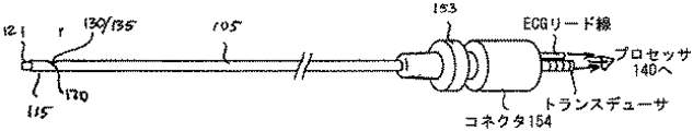
本発明の一つの実施例は、以下の要素の幾つか又は全てを含む血管アクセス及びガイダンスシステムである。すなわち、基端と末端を有する細長い本体、患者の血管の生体非結像系超音波情報を提供するように構成された細長い本体上の非血像超音波トランスデューサと、細長い本体が血管内にあるときに血管内心電図リード電気検出セグメントが患者の生体心電図信号を提供する位置にある細長い本体上の血管内心電図リード線と、非結像血管内トランスデューサからの信号と血管内心電図リード線からの信号を受信し処理するように構成されたプロセッサと、プロセッサで処理された情報の結果を表示するように構成された出力装置を有する。 One embodiment of the present invention is a vascular access and guidance system that includes some or all of the following elements. An elongated body having a proximal end and a distal end; a non-blood image ultrasound transducer on the elongated body configured to provide bio-non-imaging ultrasound information of a patient's blood vessel; and the elongated body is within the vessel Sometimes an intravascular ECG lead on the elongated body where the intravascular ECG lead electrical detection segment provides the patient's biocardiogram signal, a signal from the non-imaging intravascular transducer and a signal from the intravascular ECG lead And a processor configured to display the results of the information processed by the processor.
これらの要素は、ガイダンスシステムの適用に応じて改変又は除去してもよい。 These elements may be modified or removed depending on the application of the guidance system.
出力装置は、患者の血管内にある細長い本体の位置に関連する結果を表示する。 The output device displays results related to the position of the elongated body within the patient's blood vessel.
プロセッサは、非結像超音波トランスデューサからの信号を処理し、非結像超音波トランスデューサの視野内にある構造の有無に関連した情報を出力装置に表示するように構成されている。プロセッサで処理された情報の結果は、生体の非結像系超音波情報と生体の心電図情報に基づいて、血管内における細長い本体の位置と移動の表示を有する。 The processor is configured to process signals from the non-imaging ultrasound transducer and display information related to the presence or absence of structures within the field of view of the non-imaging ultrasound transducer on the output device. The result of the information processed by the processor includes an indication of the position and movement of the elongated body within the blood vessel based on the non-imaging ultrasound information of the living body and the electrocardiogram information of the living body.
血管内アクセス及びガイダンスシステムは、心電図信号に応答して超音波トランスデューサを駆動するように構成された超音波トランスデューサに連結されたドライバを含む。 The intravascular access and guidance system includes a driver coupled to the ultrasound transducer configured to drive the ultrasound transducer in response to the electrocardiogram signal.
超音波トランスデューサに連結されたドライバは、複数の超音波送信モードで超音波トランスデューサを駆動するように構成されている。 A driver coupled to the ultrasonic transducer is configured to drive the ultrasonic transducer in a plurality of ultrasonic transmission modes.
血管内アクセス及びガイダンスシステムは、血管内心電図リード線の末端側に配置された細長い本体上の第2の血管内心電図リード線を有し、プロセッサは該第2の血管内心電図リード線からの信号を受信し処理するように構成されている。 The endovascular access and guidance system has a second intravascular electrocardiogram lead on an elongated body disposed distal to the intravascular electrocardiogram lead, and the processor receives signals from the second intravascular electrocardiogram lead. Is configured to receive and process.
また、プロセッサは、血管内心電図リード線からの信号と第2の血管内心電図リード線からの信号を比較するように構成されている。一つの形態では、血管内心電図リード線からの信号は目標心電図信号を含み、第2の血管内心電図リード線は基準心電図信号を含む。一つの形態では、目標心電図信号と基準心電図信号は、ECG、EMG、EEG若しくはそれらの組み合わせに関連している。 The processor is also configured to compare the signal from the intravascular ECG lead with the signal from the second intravascular ECG lead. In one form, the signal from the intravascular ECG lead includes a target ECG signal and the second intravascular ECG lead includes a reference ECG signal. In one form, the target ECG signal and the reference ECG signal are associated with ECG, EMG, EEG, or a combination thereof.
血管内アクセス及びガイダンスシステムは、血管内の生理学的パラメータを検出するための別のセンサを有し、このセンサは細長い本体に沿って配置される。プロセッサは、該別のセンサからの信号を受信し処理するように構成されている。血管内の生理学的パラメータを検出するための該別のセンサは、例えば、圧力センサ、又は光学センサである。 The intravascular access and guidance system has another sensor for detecting physiological parameters in the blood vessel, which sensor is disposed along the elongated body. The processor is configured to receive and process a signal from the other sensor. The other sensor for detecting a physiological parameter in the blood vessel is, for example, a pressure sensor or an optical sensor.
プロセッサは、静脈血流方向、静脈血流速度、静脈血流特性パターン、圧力特性パターン、Aモード情報、及び優先的な非ランダム方向の流れからなる群の少なくとも一つを含む非結像超音波トランスデューサからの信号を受信して処理し、また、心電図信号、P波パターン、QRS群パターン、T波パターン、EEG信号、及びEMG信号からなる群の少なくとも一つを含む血管内心電図リード線からの信号を受信して処理するように構成されている。 The processor includes non-imaging ultrasound including at least one of the group consisting of venous blood flow direction, venous blood flow velocity, venous blood flow characteristic pattern, pressure characteristic pattern, A-mode information, and preferential non-random direction flow Receive and process signals from the transducer, and from an intravascular ECG lead that includes at least one of the group consisting of an electrocardiogram signal, a P-wave pattern, a QRS complex pattern, a T-wave pattern, an EEG signal, and an EMG signal A signal is received and processed.
他の形態では、血管内アクセス及びガイダンスシステムは、非結像超音波トランスデューサから受信した信号と血管内心電図リード線から受信した信号を記憶ように構成されたプロセッサを有する。プロセッサは、血管内心電図リード線から受信した信号に対応する非結像超音波トランスデューサから受信した記憶信号の一部を処理するように構成されている。血管内心電図リード線から受信する信号は、P波を含む。 In another form, the intravascular access and guidance system has a processor configured to store signals received from non-imaging ultrasound transducers and signals received from intravascular electrocardiogram leads. The processor is configured to process a portion of the stored signal received from the non-imaging ultrasound transducer corresponding to the signal received from the intravascular electrocardiogram lead. The signal received from the intravascular electrocardiogram lead includes a P wave.
本発明の一形態によれば、血管内装置は、基端と末端を有する細長い本体と、細長い本体上の非結像超音波トランスデューサと、血管内装置が血管内にあるときに血管内心電図リード線が血液と接する位置に設けた細長い本体上の血管内心電図リード線を有する。一つの形態では、血管内心電図リード線は、細長い本体末端に配置される。 According to one aspect of the invention, an intravascular device includes an elongated body having a proximal end and a distal end, a non-imaging ultrasound transducer on the elongated body, and an intravascular electrocardiogram lead when the intravascular device is in a blood vessel. It has an intravascular electrocardiogram lead on an elongated body provided where the wire contacts blood. In one form, an intravascular electrocardiogram lead is disposed at the elongate body end.
追加的に又は代替的に、血管内心電図リード線の電気検出セグメントは、細長い本体末端の3cm以内、非結像超音波トランスデューサの3cm以内、及び/又は非結像超音波トランスデューサの基端に配置される。 Additionally or alternatively, the electrical sensing segment of the intravascular ECG lead is located within 3 cm of the elongate body distal end, within 3 cm of the non-imaging ultrasound transducer, and / or at the proximal end of the non-imaging ultrasound transducer. Is done.
血管内装置の他の形態では、装置は、細長い本体上に設けた第2の血管内心電図リード線を有する。該リード線の位置は、血管内装置が血管内にあるときに血管内心電図リード線が血液と接する位置である。追加的に又は代替的に、第2の血管内心電図リード線の電気検出セグメントは、血管内意心電図リード線から約5cmの場所に配置されるか、または、細長い本体の末端から約5cmの場所に配置される。 In another form of intravascular device, the device has a second intravascular electrocardiogram lead provided on the elongated body. The position of the lead wire is a position where the intravascular electrocardiogram lead wire contacts the blood when the intravascular device is in the blood vessel. Additionally or alternatively, the electrical sensing segment of the second intravascular ECG lead is located about 5 cm from the endovascular ECG lead or about 5 cm from the end of the elongated body Placed in.
血管内装置の他の形態では、第2の血管内心電図リード線の電気検出セグメントは、血管内心電図リード線が目標の心電図信号を検出しているときに、第2の血管内心電図リード線が基準心電図信号を検出するように、血管内心電図リード線から離れた所定距離の位置、血管内心電図リード線が上大静脈にあるときに第2の血管内心電図リード線が上大静脈の外にあるように上大静脈の長さに関連した距離に配置される。その結果、血管内心電図リード線が心臓からの目標の心電図信号を検出するように配置されている場合、第2の血管内心電図リード線の電気検出セグメントは、比較用の基準ECG信号を検出するよう配置される。または、血管内心電図リード線の電気検出セグメントが脳からの目標心電図信号を検出するように配置されている場合、第2の血管内心電図リード線の電気検出セグメントは、比較用の基準EEG信号を検出するように配置される。または、血管内心電図リード線の電気検出セグメントが筋肉からの目標心電図信号を検出するように配置されている場合、第2の血管内心電図リード線の電気検出セグメントは、比較用の基準EMG信号を検出するように配置される。 In another form of the intravascular device, the electrical detection segment of the second intravascular ECG lead is the second intravascular ECG lead when the intravascular ECG lead is detecting a target ECG signal. A second intravascular ECG lead is located outside the superior vena cava when the intracardiac ECG lead is in the superior vena cava at a predetermined distance away from the intravascular ECG lead so as to detect the reference ECG signal It is placed at a distance related to the length of the superior vena cava. As a result, when the intravascular ECG lead is arranged to detect a target ECG signal from the heart, the electrical detection segment of the second intravascular ECG lead detects a reference ECG signal for comparison. Arranged so that. Alternatively, if the electrical detection segment of the intravascular ECG lead is arranged to detect a target ECG signal from the brain, the electrical detection segment of the second intravascular ECG lead may receive a reference EEG signal for comparison. Arranged to detect. Alternatively, if the electrical detection segment of the intravascular ECG lead is arranged to detect the target ECG signal from the muscle, the electrical detection segment of the second intravascular ECG lead may receive a reference EMG signal for comparison. Arranged to detect.
血管内装置の他の形態では、血管内心電図リード線は、細長い本体内への収納状態から細長い本体の外側の展開状態に移動可能である。一つの形態では、収納された血管内心電図リード線は、血管内装置の末端を曲げる。また、血管内心電図リード線が収納状態にある場合、電気検出セグメントは心電図信号を検出するように配置される。 In another form of intravascular device, the intravascular electrocardiogram lead is movable from a retracted state within the elongated body to a deployed state outside the elongated body. In one form, the stored intravascular ECG lead bends the distal end of the intravascular device. Also, when the intravascular electrocardiogram lead is in the retracted state, the electricity detection segment is arranged to detect an electrocardiogram signal.
血管内装置の一実施例は、細長い本体の基端を方向付けるための血管内リード線に接続された操縦要素を有し、その操縦要素は細長い本体の末端にトルクを伝える。 One example of an intravascular device has a steering element connected to an intravascular lead for directing the proximal end of the elongated body, which transmits torque to the distal end of the elongated body.
血管内心電図リード線の一実施例は、使用時に、細長い本体の周りを少なくとも部分的に伸びており、組織に傷を付けない先端を有する。 One example of an intravascular electrocardiogram lead has a tip that, when in use, extends at least partially around an elongated body and does not damage tissue.
一つの形態では、血管内装置は、形状記憶合金から形成された血管内心電図リード線を有する。追加的に又は代替的に、血管内心電図リード線は、超音波センサを血管壁から遠ざけるために使用されるように構成されている。 In one form, the intravascular device has an intravascular electrocardiogram lead formed from a shape memory alloy. Additionally or alternatively, the intravascular electrocardiogram lead is configured to be used to move the ultrasonic sensor away from the vessel wall.
他の形態では、血管内装置は被覆された金属網状構造を有し、金属網状構造の被覆の一部が除去されており、露出した金属網状構造が血管内心電図リード線電気検出セグメントとして機能する。 In another form, the intravascular device has a coated metal network, a portion of the metal network coating is removed, and the exposed metal network functions as an intravascular ECG lead electrical sensing segment. .
他の形態では、血管内装置は、血管内装置の末端に組織を傷付けない先端を有する。一つの形態では、組織を傷付けない先端は超音波レンズを有し、それは例えば拡散レンズである。 In another form, the endovascular device has a tip that does not harm tissue at the end of the endovascular device. In one form, the tip that does not damage tissue has an ultrasonic lens, such as a diffuser lens.
血管内装置は、細長い本体に設けた開口と、開口と細長い本体の基端に接続された細長い本体内のルーメンを有する。 The intravascular device has an opening in the elongate body and a lumen in the elongate body connected to the opening and the proximal end of the elongate body.
血管内装置は、生理学的パラメータを測定するために、血管内装置に別のセンサを有する。該別のセンサは、生理学的パラメータが血管内で検出された光学特性に関連している場合に使用する光学センサである。該別のセンサは、生理学的パラメータが血管内で取得された圧力測定値に関連している場合に使用する圧力センサである。該別のセンサは、生理学的パラメータが血管内で検出された音響信号に関連している場合に使用する音響センサである。 The intravascular device has another sensor on the intravascular device to measure physiological parameters. The other sensor is an optical sensor for use when the physiological parameter is related to an optical property detected in the blood vessel. The other sensor is a pressure sensor for use when the physiological parameter is related to a pressure measurement taken in the blood vessel. The other sensor is an acoustic sensor for use when the physiological parameter is related to an acoustic signal detected in the blood vessel.
細長いフレキシブルな部材は、カテーテル、ガイドワイヤ、又は探り針のような血管内装置と協働して動作するように構成してもよい。 The elongate flexible member may be configured to operate in conjunction with an intravascular device such as a catheter, guidewire, or probe.
また、細長いフレキシブルな部材は、患者に治療材料を供給するように構成してもよいし、別の装置を血管内にアクセスさせるように構成してもよい。 The elongate flexible member may also be configured to deliver therapeutic material to the patient or may be configured to allow another device to access the blood vessel.
一つの形態では、体の血管内に血管内装置を配置する方法は、血管内装置を血管内に前進させ、血管内装置の非結像超音波トランスデューサを用いて非結像超音波信号を血管内に送信することにより行われる。次に、非結像超音波トランスデューサで反射超音波信号を受信し、血管内心電図信号を血管内装置のセンサで検出する。次に、非結像超音波トランスデューサで受信した反射超音波信号とセンサで検出された血管内心電図信号を処理する。最後に、処理工程に基づいて、血管内装置を位置付ける。 In one form, a method of placing an intravascular device within a body vessel includes advancing the intravascular device into the blood vessel and using the non-imaging ultrasound transducer of the intravascular device to transmit the non-imaging ultrasound signal to the vessel. By sending it in. Next, the reflected ultrasound signal is received by the non-imaging ultrasound transducer, and the intravascular electrocardiogram signal is detected by the sensor of the intravascular device. Next, the reflected ultrasound signal received by the non-imaging ultrasound transducer and the intravascular ECG signal detected by the sensor are processed. Finally, the intravascular device is positioned based on the processing steps.
体の血管内に血管内装置を配置する方法は、適用に応じて又は実行する処理に応じて、追加の工程又は改変された工程を含む。ここで説明するガイダンスと位置付けを行うために、数々の追加の工程を設けてもよいし、それらを組み合わせて使用してもよい。追加の工程は、体に挿入された血管内装置の長さが手術前に推定された装置の長さに等しいことを確認する工程、及び/又は、体に挿入される血管内装置の長さをシステムに入力する工程を含む。また、血管内心電図信号を患者に配置されたセンサで検出する工程を追加してもよい。 The method of placing an intravascular device in a body vessel includes additional or modified steps depending on the application or the process to be performed. In order to perform the guidance and positioning described here, a number of additional steps may be provided, or a combination thereof may be used. The additional steps include verifying that the length of the intravascular device inserted into the body is equal to the estimated device length prior to surgery, and / or the length of the intravascular device inserted into the body. Input to the system. Moreover, you may add the process of detecting the intravascular electrocardiogram signal with the sensor arrange | positioned at the patient.
そのセンサは患者に取り付けるか、血管内装置に第2のセンサを設ける。装置又は患者に設けたセンサからの血管内心電図信号を装置に設けた第2のセンサからの血管内心電図信号と比較する工程を追加してもよい。 The sensor is attached to the patient or a second sensor is provided on the intravascular device. A step of comparing an intravascular electrocardiogram signal from a sensor provided on the apparatus or patient with an intravascular electrocardiogram signal from a second sensor provided on the apparatus may be added.
処理方法とアルゴリズムは、ガイダンス、配置、関係付けに有効な重要又は独特な特性を特定するために、改変してもよいし、組み合わせてもよい。その方法は、超音波及び/又は心電図信号情報を処理するために、異なる又は特注のソフトウェア又はプログラムを含む。処理工程は、洞房結合を特定するため、又は速度プロファイルの最も高い平均速度を求めるために、反射超音波信号を処理することを含む。 Processing methods and algorithms may be modified or combined to identify important or unique properties useful for guidance, placement, and association. The method includes different or custom software or programs for processing ultrasound and / or electrocardiogram signal information. The processing step includes processing the reflected ultrasound signal to identify sinoatrial coupling or to determine the highest average velocity of the velocity profile.
処理工程は、血管内心電図信号を処理して、心電図群におけるピークツーピーク振幅変化、心電図におけるQRS群のピークツーピーク振幅変化、心電図におけるR波のピークツーピーク振幅変化、心電図におけるP波のピークツーピーク振幅変化を求めること、また、追加的に又は代替的に、超音波情報を取得及び/又は処理するためのトリガーとして心電図情報を使用することを含む。 The processing step processes the intravascular ECG signal to change the peak-to-peak amplitude change in the ECG group, the peak-to-peak amplitude change of the QRS group in the ECG, the peak-to-peak amplitude change of the R wave in the ECG, and the peak of the P wave in the ECG Determining a two-peak amplitude change, and additionally or alternatively, using the electrocardiogram information as a trigger for acquiring and / or processing ultrasound information.
処理方法とアルゴリズムは、体の骨格構造又は位置に対する血管内装置の位置を求めるために、重要な又は独特な特性を特定するために改変又は組み合わせてもよい。これらの方法の例は、洞房結合、洞房結節、上大静脈、内頸静脈、及び鎖骨下静脈に対する血管内装置の位置を求めるための処理を行うことを含む。 Processing methods and algorithms may be modified or combined to identify important or unique characteristics in order to determine the position of the endovascular device relative to the skeletal structure or position of the body. Examples of these methods include performing processing to determine the position of the endovascular device relative to the sinoatrial junction, sinoatrial node, superior vena cava, internal jugular vein, and subclavian vein.
体の血管内に血管内装置を配置する方法はさらに、体の血管内に装置を固定する場所を求めるために血管内装置を用いること、また、血管内装置で求めた位置に装置を維持するために装置と共に血管内装置を体に固定することを含むように改変してもよい。体の血管内に血管内装置を配置する方法は、装置の現在の位置を計算する工程と、計算された現在の装置の位置を処理工程で示された位置と比較する工程を含む。その方法の工程は、血管内装置を所望の場所に配置するために、全体として又は部分的に任意の順序で又は繰り返し行うことができる。例えば、体の血管内に血管内装置を配置する方法は、血管内装置が冠状静脈洞に対して右心房内に配置されるまで、上記処理工程と配置工程を実行することを含む。代わりに、体の血管に血管内装置を配置する方法は、血管内装置が肺静脈に対して左心房に配置されるまで、上記処理工程と配置工程を実行することを含む。代わりに、体の血管に血管内装置を配置する方法は、血管内装置が大動脈内に配置されるまで、上記処理工程と配置工程を実行することを含む。 The method of placing an intravascular device within a body vessel further uses the intravascular device to determine where to secure the device within the body vessel and also maintains the device in the position determined by the intravascular device. Therefore, it may be modified to include securing an intravascular device with the device to the body. A method of placing an intravascular device within a body vessel includes calculating a current position of the device and comparing the calculated current position of the device with the position indicated in the processing step. The method steps can be performed in any order or repeated in whole or in part to place the intravascular device at the desired location. For example, a method of placing an intravascular device within a body vessel includes performing the above processing and placement steps until the intravascular device is placed in the right atrium with respect to the coronary sinus. Instead, a method of placing an intravascular device in a body vessel includes performing the above processing and placement steps until the intravascular device is placed in the left atrium with respect to the pulmonary vein. Instead, a method of placing an intravascular device in a body vessel includes performing the above processing and placement steps until the intravascular device is placed in the aorta.
この形態は、例えば、処理工程の結果を表示する追加の工程を含む。処理工程はまた、静脈血流方向に関する情報を含む。静脈血流方向は、センサに向かう方向の流れと、センサから離れる方向の流れがある。追加的に又は代替的に、処理工程の結果は、静脈血流速度に関連した一つ以上の情報、すなわち、静脈血流特性パターンに関連した情報、圧力特性パターンに関連した情報、超音波Aモード情報に関連した情報、反射超音波内の優先的な非ランダムな流れの方向に関連した情報、脳の電気的活動に関連した情報、筋肉の電気的活動に関連した情報、心臓の電気的活動に関連した情報、洞房結節の電気的活動に関連した情報、及びECGから心臓の電気的活動に関する情報のいずれかを含む。 This form includes, for example, an additional step of displaying the result of the processing step. The processing step also includes information regarding the venous blood flow direction. The venous blood flow direction includes a flow toward the sensor and a flow away from the sensor. Additionally or alternatively, the result of the processing step is one or more information related to venous blood flow velocity, ie information related to venous blood flow characteristic pattern, information related to pressure characteristic pattern, ultrasound A Information related to mode information, information related to preferential non-random flow direction in reflected ultrasound, information related to brain electrical activity, information related to muscle electrical activity, heart electrical Information relating to activity, information relating to electrical activity of the sinoatrial node, and information relating to electrical activity of the heart from the ECG.
他の形態では、表示工程は、装置の位置の視覚的表示を含むように改変できる。 In other forms, the display process can be modified to include a visual display of the position of the device.
表示工程は、装置の位置を視覚的又は色表示する、又は装置の位置を示す音声表示と組み合わせて表示するように改変してもよい。 The display step may be modified to display the position of the device visually or in color, or in combination with an audio display indicating the position of the device.
体の血管内に血管内装置を配置する方法は、センサで受信された血管内心電図信号に同期して反射超音波信号を収集する工程を含むように改変できる。 The method of placing an intravascular device within a body vessel can be modified to include collecting reflected ultrasound signals in synchronization with an intravascular electrocardiogram signal received by a sensor.
別の形態は、例えば、血管内心電図が、心臓、脳、筋肉からの電気的活動を含む場合に可能である。収集工程は、生理学的行為に対応するようにタイミングが合わされる。例えば、収集工程は、PR期間中に同期して行われるか、P波に一部に同期して行われる。 Another form is possible, for example, when an intravascular electrocardiogram includes electrical activity from the heart, brain, and muscle. The collection process is timed to correspond to physiological actions. For example, the collection process is performed in synchronization with the PR period or partially in synchronization with the P wave.
EEG、ECG、又はEMG電位図の他の部分は、装置のセンサ又は患者のセンサからの情報を収集する、処理する、及び/又は記憶するタイミングを取るため利用される。体の血管内に血管内装置を配置する方法の一形態では、送信工程、受信工程、及び処理工程が、選択された血管内心電図信号が検出されたときだけ実行される。方法の一形態では、選択された血管内電気信号は、ECG波の一部である。方法の他の形態では、選択された血管内電気信号は、EEG波の一部である。方法の他の形態では、選択された血管内電気信号は、EMG波の一部である。 Other parts of the EEG, ECG, or EMG electrogram are utilized to time, collect, process, and / or store information from device sensors or patient sensors. In one form of placing an intravascular device in a body vessel, the transmitting, receiving, and processing steps are performed only when a selected intravascular electrocardiogram signal is detected. In one form of the method, the selected intravascular electrical signal is part of an ECG wave. In another form of the method, the selected intravascular electrical signal is part of an EEG wave. In another form of the method, the selected intravascular electrical signal is part of an EMG wave.
体の血管内に血管内装置を配置する方法は、反射超音波内の非結像超音波情報を利用して血管内の構造を特定することを含む。一つの形態では、血管内の構造を特定するためにAモード超音波を使用する。別の形態では、該構造近傍の流れパターンを特定するためにドップラー超音波情報を使用する。 A method for placing an intravascular device within a body vessel includes identifying non-imaging ultrasound information within reflected ultrasound to identify structures within the vessel. In one form, A-mode ultrasound is used to identify structures within the blood vessel. In another form, Doppler ultrasound information is used to identify the flow pattern near the structure.
体の血管内に血管内装置を配置する方法では、処理工程は、選択された心電図トリガー信号に対応する反射超音波信号の一部でのみ実行される。この方法は、例えば、選択された心電図トリガー信号がECG波の一部、EEG波の一部、EMG波の一部である場合に採用される。 In the method of placing an intravascular device in a body vessel, the processing step is performed only on a portion of the reflected ultrasound signal corresponding to the selected electrocardiogram trigger signal. This method is employed, for example, when the selected electrocardiogram trigger signal is a part of an ECG wave, a part of an EEG wave, or a part of an EMG wave.
体の血管内に血管内装置を配置する方法では、処理工程は、血管内装置から遠ざかる方向の流れエネルギーを血管内装置に向かう方向の流れエネルギーを比較することによって反射超音波信号を処理するように改変できる。一つの形態では、比較のために、2cm/秒〜25cm/秒内の血流に関連した流れエネルギーを選択する。 In the method of placing an intravascular device in a body vessel, the processing step is adapted to process the reflected ultrasound signal by comparing the flow energy in a direction away from the intravascular device with the flow energy in the direction toward the intravascular device. Can be modified. In one form, the flow energy associated with blood flow within 2 cm / sec to 25 cm / sec is selected for comparison.
他の形態では、体の血管内に血管内装置を配置する方法は、反射超音波を処理して流れパターンの脈動流の指標を検出する工程を含む。脈動流の指標は、多数の異なるパラメータのいずれであってもよい。脈動流の指標には、静脈流パターン、動脈流パターン、又は心臓の心房機能である。 In another form, a method of placing an intravascular device within a body vessel includes processing reflected ultrasound to detect a pulsating flow index of a flow pattern. The indicator of pulsating flow can be any of a number of different parameters. An indicator of pulsatile flow is a venous flow pattern, an arterial flow pattern, or an atrial function of the heart.
体の血管内に血管内装置を配置する方法は、P波の相対振幅を心電図の他の一部の相対振幅と比較するために血管内心電図信号を処理する工程を含むように処理工程を改変してもよい。一つの形態では、心電図の別の一部は、QRS群を含む。処理工程は、血液の速度プロファイルを求めるために反射超音波を処理すること、また、血管内心電図の形状を求めるために検出血管内電気信号を処理することを含むように改変できる。処理工程は、血管内での血管内装置の位置を求めるために、血液の流れ速度プロファイルと血管内心電図の形状を関連付ける工程を含むように改変できる。 A method for placing an intravascular device within a body vessel modifies the processing step to include processing the intravascular ECG signal to compare the relative amplitude of the P-wave with the relative amplitude of other portions of the ECG. May be. In one form, another part of the electrocardiogram includes a QRS complex. The processing steps can be modified to include processing the reflected ultrasound to determine the blood velocity profile and processing the detected intravascular electrical signal to determine the shape of the intravascular electrocardiogram. The processing step can be modified to include associating the blood flow velocity profile with the shape of the intravascular electrocardiogram to determine the position of the intravascular device within the blood vessel.
血管内アクセス及びガイダンスシステムの一形態は、
患者の血管にアクセスできるように構成された細長いフレキシブルな部材と、
細長いフレキシブルな部材の末端に配置され、患者の血管と心臓の生体非結像超音波情報を提供するように構成されたセンサと、
細長いフレキシブルな部材の末端に配置され、患者の血管と心臓の生体電気信号(心電図)を提供するように構成されたセンサと、
生体の非結像超音波情報と、上記センサから提供された患者の血管と心臓の心電図情報を受信して処理し、また、患者の血管内と心臓内に細長いフレキシブルな部材の末端を配置するための位置情報を提供するように構成されたプロセッサと、
及び/又は、プロセッサからの位置情報を出力するように構成された出力装置のいずれかを含む。
One form of intravascular access and guidance system is:
An elongated flexible member configured to provide access to a patient's blood vessel;
A sensor disposed at the distal end of the elongate flexible member and configured to provide biological non-imaging ultrasound information of the patient's blood vessels and heart;
A sensor disposed at the distal end of the elongated flexible member and configured to provide bioelectric signals (electrocardiograms) of the patient's blood vessels and heart;
Receive and process non-imaging ultrasound information of the living body and electrocardiogram information of the patient's blood vessel and heart provided from the sensor, and place the end of the elongated flexible member in the patient's blood vessel and in the heart A processor configured to provide location information for:
And / or any output device configured to output position information from the processor.
一つの形態では、血管内アクセス及びガイダンスシステムで使用されるプロセッサは、
センサで提供された患者の血管系の生体非結像超音波情報を処理して、出力情報に、視野内に構造と対象物を表示すること、
生体の非結像超音波情報と患者の血管系の心電図情報を処理して、出力情報に、患者の血管内の所望方向に関する細長いフレキシブルな部材の移動を示すこと、
静脈血流方向、静脈血流速度、静脈血流特性パターン、圧力特性パターン、Mモード情報及び優先的な非ランダム方向の流れ、心電図信号、P波パターンQRS群パターン、T波パターンからなる群から選択されたパラメータに基づいて、患者の血管系の生体非結像超音波情報を処理することのいずれかを含む。
In one form, the processor used in the endovascular access and guidance system is:
Processing the biological non-imaging ultrasound information of the patient's vasculature provided by the sensor and displaying the structure and object in the field of view in the output information
Processing the non-imaging ultrasound information of the living body and the electrocardiogram information of the patient's vasculature, and indicating in the output information the movement of the elongated flexible member with respect to the desired direction within the patient's blood vessel;
From the group consisting of venous blood flow direction, venous blood flow velocity, venous blood flow characteristic pattern, pressure characteristic pattern, M-mode information and preferential non-random flow, electrocardiogram signal, P wave pattern QRS group pattern, T wave pattern Processing any non-imaging ultrasound information of the patient's vasculature based on the selected parameters.
血管内アクセス及びガイダンスシステムは、追加のセンサを備えていてもよい。この場合、センサと2つ以上の追加のセンサは、細長いフレキシブルな部材に取り付けられて、フレキシブルな部材に沿った複数の場所で測定を行う。血管内アクセス及びガイダンスシステムは、取得データから得られたフィードバック情報に応答して、装置先端を方向付ける操縦要素を有する。血管内アクセス及びガイダンスシステムは、取得データから得られたフィードバック情報に応答して、装置先端を方向付けるトルク制御部を有する。 The intravascular access and guidance system may include additional sensors. In this case, the sensor and the two or more additional sensors are attached to an elongated flexible member to take measurements at multiple locations along the flexible member. The endovascular access and guidance system has a steering element that directs the device tip in response to feedback information obtained from acquired data. The intravascular access and guidance system has a torque controller that directs the tip of the device in response to feedback information obtained from acquired data.
一つの形態では、体の血管系に器具を配置する方法は、
体の血管にアクセスする工程、
体の血管内に器具を配置する工程、
体の静脈系に超音波信号を送信するために器具を使用する工程、
2〜20cm/秒の間の流れ速度を示す血管からの反射超音波信号を受信するために器具を使用する工程、
心臓の洞房結節の近傍を示す血管内心電図を記録するために器具を使用する工程、
静脈血流方向、静脈血流速度、静脈血流特性パターン、圧力特性パターン、Aモード情報及び優先的な非ランダム方向の流れ、心電図信号、P波パターン、QRS群パターン、T波パターンからなる群から一つ又は複数のパラメータを求めるために反射超音波信号と心電図を処理する工程、
及び、一つ又は複数の決定パラメータ又は血管内のパラメータを用いて血管内で器具を前進する工程、のいずれかを含む。
In one form, a method for placing an instrument in the body's vasculature comprises:
Accessing the blood vessels of the body,
Placing an instrument in a blood vessel of the body,
Using an instrument to transmit an ultrasound signal to the venous system of the body;
Using the instrument to receive a reflected ultrasound signal from a blood vessel exhibiting a flow velocity between 2 and 20 cm / sec;
Using the instrument to record an intravascular electrocardiogram showing the vicinity of the sinoatrial node of the heart;
Group consisting of venous blood flow direction, venous blood flow velocity, venous blood flow characteristic pattern, pressure characteristic pattern, A-mode information and preferential non-random flow, electrocardiogram signal, P wave pattern, QRS group pattern, T wave pattern Processing the reflected ultrasound signal and the electrocardiogram to determine one or more parameters from
And advancing the instrument within the blood vessel using one or more determined parameters or parameters within the blood vessel.
体の血管内に器具を配置する方法は、
配置されようとしている器具を用いて体の血管内に向けて又はそこからAモード超音波信号を送信又は受信する工程、
体の血管に向けて又はそこからドップラー超音波信号を送信又は受信する工程、
体の血管に向けて又はそこから非結像ターゲット追跡用超音波信号を送信又は受信する工程、
器具を用いて体の血管から血管内及び心臓内の心電図を記録する工程、
反射超音波信号と血管内心電図を処理して流れパターンを求めると共に血管内で器具に向かう流れ方向を決定する工程、
反射超音波信号を処理して流れパターンを求めると共に血管内で器具から離れる流れ方向を決定する工程、
反射超音波信号と血管内心電図を処理して特定の血流パターンと特定の心電図パターンを示す信号の存在を求める工程、
反射超音波信号と血管内心電図を処理して洞房結合と洞房結節に対する器具の位置を求める工程、
反射超音波信号を処理して特定の構造(血液の凝集を含む)を示す信号の存在を判断する工程、
反射超音波信号と血管内心電図を処理して内頸静脈に対する器具の位置を求める工程、
反射超音波信号と血管内心電図を処理して鎖骨下静脈に対する器具の位置を求める工程、
器具で収集された情報を用いて、体の血管内の装置の位置を求めて固定する工程、
決められた場所に装置を維持するために体に該装置を固定する工程、
器具からの情報を用いて装置の現在の位置を計算する工程、
計算工程に基づいて、装置の計算された現在の位置と器具によって求めた位置を比較して、装置が器具によって決められた場所にあるか否かを判断する工程、
反射超音波信号と血管内ECGを処理して冠状静脈洞に対する右心房内の器具の位置を求める工程、
及び/又は、反射超音波信号と血管内ECGを処理して肺静脈に対する左心房内の器具の位置を求める工程のいずれかを含む。
The method of placing the instrument in the blood vessels of the body
Transmitting or receiving an A-mode ultrasound signal into or out of a blood vessel of the body using the instrument to be placed;
Transmitting or receiving a Doppler ultrasound signal toward or from a blood vessel of the body;
Sending or receiving ultrasound signals for tracking non-imaging targets towards or from the blood vessels of the body;
Recording electrocardiograms in the blood vessels and in the heart from the blood vessels of the body using an instrument;
Processing the reflected ultrasound signal and the intravascular ECG to determine a flow pattern and determining a flow direction toward the instrument within the blood vessel;
Processing the reflected ultrasound signal to determine a flow pattern and determining a flow direction away from the instrument in the blood vessel;
Processing the reflected ultrasound signal and the intravascular ECG to determine the presence of a specific blood flow pattern and a signal indicative of the specific ECG pattern;
Processing the reflected ultrasound signal and the intravascular electrocardiogram to determine the position of the instrument relative to the sinoatrial junction and sinoatrial node;
Processing the reflected ultrasound signal to determine the presence of a signal indicative of a particular structure (including blood agglutination);
Processing the reflected ultrasound signal and the intravascular ECG to determine the position of the device relative to the internal jugular vein;
Processing the reflected ultrasound signal and the intravascular ECG to determine the position of the device relative to the subclavian vein;
Using the information collected by the instrument to determine and fix the position of the device within the body's blood vessels,
Securing the device to the body to maintain the device in place;
Calculating the current position of the device using information from the instrument;
Comparing the calculated current position of the device with the position determined by the instrument based on the calculation step to determine whether the apparatus is in a location determined by the instrument;
Processing the reflected ultrasound signal and intravascular ECG to determine the position of the instrument in the right atrium relative to the coronary sinus;
And / or processing the reflected ultrasound signal and the intravascular ECG to determine the position of the instrument in the left atrium relative to the pulmonary vein.
本明細書で言及する全ての特許、刊行物、特許出願は、それぞれの特許、刊行物、又は特許出願が具体的に個別的に引用をもって組み込まれると示されている場合、すべてここに引用をもって組み込まれる。 All patents, publications, and patent applications referred to herein are hereby incorporated by reference, where each patent, publication, or patent application is specifically and individually indicated to be incorporated by reference. Incorporated.
本発明の新規な特徴は、特許請求の範囲に特に記載されている。発明の原理を利用した実施例を記載した以下の詳細な説明と添付図面を参照することにより、本発明の特徴と利点が理解できる。 The novel features of the invention are set forth with particularity in the appended claims. The features and advantages of the present invention may be understood by reference to the following detailed description that sets forth illustrative embodiments, in which the principles of the invention are utilized, and the accompanying drawings of which:
[発明の詳細な説明]
本発明の実施例は、ガイド付血管アクセス装置からの信号を処理するガイド付血管アクセス装置とシステム、及び、処理装置からの出力に基づいてユーザに情報を提供するユーザインターフェイスを提供する。図1は、典型的な血管内アクセス及びガイダンスシステム100の一実施例を示す。システム100は、基端110と末端115を備えた細長い本体105を有する。細長い本体105は、患者1の血管系への挿入及び該血管系を進むように構成された種々の血管内装置の任意のものである。図1は、尺側皮静脈6に挿入された末端115を示している。この図示する実施例において予想される移動経路(点線20)は、心臓20の一部、又は、洞房結節(SAノード)8の近傍の上大静脈14内に入っている。大動脈3、肺動脈、肺静脈11、頸動脈10、腕頭静脈12、下大静脈16、及び房室結節(AVノード)9もまた、この図に示されている。
Detailed Description of the Invention
Embodiments of the present invention provide a guided vascular access device and system for processing signals from a guided vascular access device, and a user interface that provides information to a user based on output from the processing device. FIG. 1 illustrates one embodiment of a typical intravascular access and
図1には示さず、以下に詳細に説明するが、細長い本体105は、体内の生理学的パラメータを測定する少なくとも2つのセンサを含む。幾つかの実施例では、一つのセンサは、患者1の血管系の超音波情報に基づいて体内の非画像を提供するように構成された、細長い本体105に設けた非画像超音波変換器(トランスデューサ)である。幾つかの実施例では、その他のセンサは、細長い本体105上の所定の場所に設けた血管系電気記録リード線で、細長い本体105が血管系内にあるとき、該血管系電気記録リード線の検出セグメントが患者1の体内電気信号を与える。図1は、血管系の外側にある第2の電気記録センサを用いることを示している。電極112は、患者1の血管系の外部に配置されている。電極112は電気記録情報を検出し、その情報はリード線111を介してプロセッサ140に送られる。
Although not shown in FIG. 1 and described in detail below, the
代わりに、電極112に代えて、又は電極112に加えて、別の電気記録センサを細長い本体105に設けてもよい。一つ以上の電気記録センサを、細長い本体に設けてもよい。この場合、プロセッサ140は、細長い本体105によって提供される追加の電気記録センサ(又はその他のセンサ)からの情報を受信し、処理し、比較し、関連付けるように構成される。細長い本体105の電気記録リード線又はセンサは、ガイダンスシステム100の位置と配置を容易にするために、目的の電気記録信号と基準電気記録信号を得るべく、細長い本体105に関連して設けてもよいし、相互に関連して設けてもよい。目的の電気記録信号と基準電気記録信号は、(a)心電図(ECG)のすべて又は一部を含む心臓の電気的活動、(b)脳電図(EEG)のすべて又は一部を含む脳の電気的活動、(c)筋肉又は筋肉群に関連した筋電図のすべて又は一部を含む筋肉又は筋肉群の電気的活動の一つ又はそれ以上に関連付けてもよい。センサや細長い本体105の種々の代替形状の詳細は、少なくとも図2〜図5Bに説明されている。
Alternatively, another electrorecording sensor may be provided on the
システム100はまた、非画像超音波変換器からの信号や血管系電気記録リード線からの信号を受信して処理するように構成されたプロセッサ140を有する。プロセッサ140は、通常の超音波や電気記録信号を処理するものと同様に、超音波や電気記録信号を受信して処理する通常の処理能力を有する。通常の処理能力は、対応するセンサのデータを受信し、処理し、格納するために必要な一般的な構成を含むものである。細長い本体のセンサを用いてECG活動を検出する場合、適当な心電図記録法の構成と処理能力が与えられる。EEG信号処理、EMG信号処理、音響センサ処理、圧力センサ処理、光学センサ処理などについても同様のことが言える。
The
しかし、通常の超音波システムや電気記録システムと違って、プロセッサ140は、センサからの信号処理し、流れと電気パターンを同定し関連づけて、本明細書で説明するように、細長い本体105の案内、位置付け、及び配置場所の確認を支援するためのプログラミング能力と処理能力を有する。
However, unlike conventional ultrasound or electrical recording systems, the
一つの形態では、プロセッサ140は、ソフトウェア、ファームウェア、又はその他のプログラミング機能を用いて構成されており、静脈血流方向、静脈血流速度、静脈血流特性パターン、圧力特性、Aモード情報、及び優先的な非ランダムな流れ方向からなる群の少なくとも一つの信号を含む非撮像超音波トランスデューサからの信号を受信して処理する。また、プロセッサ140は、ソフトウェア、ファームウェア、又はその他のプログラミング機能を用いて構成されており、心電図信号、P波パターン、QRS群特性、T波特性、EEG信号、及びEMG信号からなる群から少なくとも一つの信号を含む血管内の心電リード線からの信号を受信して処理する。
In one form, the
一つの形態では、一つのセンサからの信号は、別のセンサからの信号を取得したり又は処理したりするためのトリガーである。このように、2つの異なる生理的センサからのデータは、時間的に相互に関連があり、また、そのトリガー信号と相互に関連があり得る。代案として、トリガーされたセンサからデータ取得をトリガーするのではなく、すべてのセンサのデータを集めて、及び/又は、記憶したり、代わりに、そのトリガーからトリガデータに基づいてデータのサブセットだけを処理することができる。いずれのトリガスキームにおいても、トリガーするセンサのデータとトリガーされたセンサのデータは、共に処理されて以下に説明する利益をもたらす。トリガーの一つの実施例では、超音波センサからの超音波データを取得するためのトリガー信号として、電気記録センサからのP波検出を利用している。上述のように、電気記録リード線が洞房結節8の近くで上大静脈に配置されているときに検出される特有のP波は、血管系の当該領域でも起こる独特な血流特性の検出を確認するために使用できる。このように、2つの異なる生理系からの2つの独特な生理学的信号の存在は、以下に説明するガイダンスシステムの実施例の正確性を増す。
In one form, a signal from one sensor is a trigger for acquiring or processing a signal from another sensor. In this way, data from two different physiological sensors can be correlated with each other in time and with the trigger signal. As an alternative, instead of triggering data acquisition from the triggered sensor, the data of all sensors can be collected and / or stored, or instead only a subset of the data based on the trigger data from that trigger. Can be processed. In either triggering scheme, the triggering sensor data and the triggered sensor data are processed together to provide the benefits described below. In one embodiment of the trigger, P-wave detection from an electric recording sensor is used as a trigger signal for acquiring ultrasonic data from the ultrasonic sensor. As mentioned above, the unique P-wave detected when the electrical recording lead is placed in the superior vena cava near the
システム100はまた、プロセッサ140で処理された情報の結果を表示するように構成された出力装置130を有する。
The
表示装置は、プロセッサ140と同様に、従来の表示装置に見られる特性を有する。本発明の表示装置140は、プロセッサ140による独特の処理とそれによって求められた結果に関連した情報を表示するように構成されているという点で、通常の表示装置と異なる。一つの形態では、出力装置140は、患者の血管内の細長い本体の位置に関連する結果を表示する。別の形態では、プロセッサで処理された情報の結果は、体内の非画像を基礎とした超音波情報と体内の電気記録情報に基づく、血管系内における細長い本体105の位置又は移動の指標を含む。表示装置130は、ユーザが任意の適当な方法(例えば、カラー、統計図表、音、又はその他の適当な手法を用いた視覚的方法)で認識するように、その情報を表示すべく構成されている。
The display device, like the
本発明に係る実施例の他の形態は、血管系にカテーテルを配置し、案内し、位置付けるために、経脈管的に測定された生理学的パラメータを使用することに関する。一つの形態において、本発明の実施例は、血液の流れ、速度、圧力、または血管内ECGなどの生理学的パラメータの測定のための内蔵センサを備えた血管内部材アセンブリに関する。別の形態では、本発明の実施例は、当該場所で測定された生理学的パラメータの特性に基づいて、血管内の個々の場所を特定し認識することができるデータ処理アルゴリズムに関する。また別の形態では、本発明の実施例は、血管系又は血管内において関心のある対象等の構造(Aモードや血流速度等の測定されたパラメータのパターンに基づいて血液凝固)を特定し認識できるデータ処理アルゴリズムに関する。別の形態では、本発明の実施例は、案内及び位置付けの情報を示し、血液凝固などの関心のある対象を示すユーザインターフェイスを備えた器具に関する。例えば、この形態では、プロセッサは、非画像超音波トランスデューサからの信号を処理し、非画像超音波トランスデューサの視野内に構造が存在することに関する情報を出力装置に表示するように構成されている。 Another form of embodiment according to the present invention relates to the use of transvascularly measured physiological parameters to place, guide and position a catheter in the vasculature. In one form, embodiments of the invention relate to an intravascular member assembly with a built-in sensor for measurement of physiological parameters such as blood flow, velocity, pressure, or intravascular ECG. In another form, embodiments of the invention relate to a data processing algorithm that can identify and recognize individual locations within a blood vessel based on characteristics of physiological parameters measured at that location. In another form, embodiments of the present invention identify structures of interest (such as blood coagulation based on measured parameter patterns such as A-mode and blood flow velocity) within the vasculature or blood vessels. It relates to a recognizable data processing algorithm. In another form, embodiments of the present invention relate to an instrument with a user interface that provides guidance and positioning information and indicates a subject of interest such as blood clotting. For example, in this form, the processor is configured to process signals from the non-image ultrasound transducer and display information on the presence of the structure in the field of view of the non-image ultrasound transducer on the output device.
また、他の形態では、本発明の実施例は、センサを利用した血管内部材によって提供される位置情報に基づいて、ユーザによって血管系内で血管内部材を案内し位置付ける方向に関する。本発明の他の形態の実施例は、カテーテル又は探り針若しくはガイドワイヤをガイドとして使用して血管系内の特定の場所に配置し案内し位置付けるために、案内される以下の血管アクセスデバイス及びシステムを用いて特定されていた、経脈管的に測定された生理学的パラメータを使用することに関する。 In another aspect, embodiments of the invention relate to a direction in which a user guides and positions an intravascular member within a vascular system by a user based on positional information provided by the intravascular member utilizing a sensor. Another embodiment of the present invention is the following guided vascular access device and system for placement and guidance and positioning at specific locations within the vasculature using a catheter or probe or guidewire as a guide: To use physiological parameters measured transvascularly that have been specified using
本発明は、異なる生理学的パラメータの信号におけるパターンやそれらの信号パターンの関係を認識して、血管系装置を血管内で案内して配置するための新規な方法、装置、及びシステムを提供する。一つの実施例では、末梢から中心静脈まで挿入するカテーテル(PICC)などのカテーテルが挿入され前進され配置され、血流パターン、心電図信号、及び関心のある場所おけるそれらの相互関係の認識に基づいて、血管系内でモニタする。 The present invention provides novel methods, devices, and systems for recognizing patterns in signals of different physiological parameters and the relationships between those signal patterns to guide and position vascular devices within a blood vessel. In one embodiment, a catheter, such as a catheter that is inserted from the peripheral to the central vein (PICC), is inserted and advanced and positioned, based on recognition of blood flow patterns, ECG signals, and their interrelationships at locations of interest. Monitor in the vasculature.
ここで紹介する新規な装置と方法の一つの利点は、寝床の側で行われる配置法において血管系装置を正しく配置する可能性が高まるということである。また、ここで説明する配置法の正確性と冗長性ゆえに、新規な方法、装置、システムを使用することにより、画像案内、特に、位置を確認するためのX線画像及び/又は撮像を必要とすることなく、また、装置の遊走もなく、血管系装置を配置できる。ここで紹介する新規な装置と方法の他の利点は、血管内、または、故障したカテーテル(例えば、中心線)の原因を確認するカテーテル内の血液凝固を検出できることである。 One advantage of the novel device and method introduced here is that it increases the likelihood of correctly placing the vascular device in the placement method performed on the bedside. Also, because of the accuracy and redundancy of the placement method described here, the use of novel methods, devices, and systems requires image guidance, particularly X-ray images and / or imaging to confirm location. The vasculature device can be placed without the need for device migration. Another advantage of the novel apparatus and method introduced here is that blood clotting can be detected in a blood vessel or in a catheter that identifies the cause of a failed catheter (eg, centerline).
また別の利点は、以下で説明する案内される血管アクセス装置及びシステムは、血管系装置を血管系に配置するための既存の医療のワークフローに組み込むことができる、ということに関係している。さらに具体的に説明すると、本発明の実施例は、例えば、センサを利用してカテーテル及び/又はガイドワイヤを血管内で案内し配置する、センサを利用した新規な血管内装置、システム、及び方法を提供するものである。したがって、適正に配置されたセンサを利用した血管内装置は、例えば、(a)心臓弁置換手術用の心臓弁の場所、(b)血管内又は腎臓内の治療のために腎静脈の同定、(c)下大静脈(IVC)フィルタ置換のために腎静脈及び/又は下大静脈の同定、(d)ペーシング用リード線又は僧帽弁改変装置を設置するために冠状静脈洞の場所、(e)センサの配置及び/又は心房細動のアブレーション治療等の治療の遂行のための肺静脈の場所などの体内で、他の血管内装置の展開を案内するか、診断手技又は治療手技の実行を容易にするために使用されるとともに、及び、ここで説明するセンサ関連技術によって特定される血管内の特定の場所に装置を設置し又はそこでの治療の遂行によって得られる各種診断手技又は治療手技などで使用される。 Another advantage relates to the guided vascular access devices and systems described below can be incorporated into existing medical workflows for placing vascular devices in the vascular system. More specifically, embodiments of the present invention provide novel intravascular devices, systems, and methods utilizing sensors that, for example, use a sensor to guide and position a catheter and / or guidewire within the blood vessel. Is to provide. Thus, intravascular devices utilizing properly positioned sensors can include, for example, (a) the location of a heart valve for heart valve replacement surgery, (b) the identification of a renal vein for intravascular or intrarenal treatment, (C) identification of renal veins and / or inferior vena cava for inferior vena cava (IVC) filter replacement; (d) location of coronary sinus to install pacing lead or mitral valve modification device; e) guiding the deployment of other intravascular devices within the body, such as the location of the pulmonary veins for performing the placement of sensors and / or ablation treatment of atrial fibrillation, or performing diagnostic or therapeutic procedures And various diagnostic or therapeutic techniques obtained by installing the device at a specific location within a blood vessel or performing a treatment there, as specified by the sensor-related techniques described herein. Used in etc. It is.
幾つかの実施例では、ここで説明する新規なガイドシステムの実施例に係るシステムと方法は、静脈系の血管内で、ここで説明するセンサを具備したカテーテル及び/又はガイドワイヤを配置し案内し位置付けるために利用される。ここで説明する実施例は、動脈系の血管内でも利用できる。一つの形態では、以下に説明する案内される血管アクセス装置は、多数の医療装置で使用される血管内カテーテルを案内し、位置付けし、配置確認のために利用できる。本発明の実施例から利益を受ける例示の医療装置は、例えば、中心静脈アクセスカテーテル(PICC)や血液透析カテーテルを配置すること、カテーテルを配置すること、及び脳卒中の治療のために脳の血管内に血管装置を位置付けること、リード線を配置すること、又は他の脳治療装置又は静脈瘤血管の経皮治療のために治療装置を配置すること、を含む。また、特定の筋肉又は筋肉群が、ここで説明する一つ又は複数の方法と装置を支援するEMG刺激及び/又はセンサ回収のために選択される。その場合、血管内の位置を確認し及び/又は関連付けるためにEMG信号が利用される。この形態は、例えば、静脈瘤血管の位置確認、大腿動脈の位置確認、又は大伏在動脈内部での血管採取装置の位置付けに、特に有益である。 In some embodiments, the systems and methods according to the novel guide system embodiments described herein place and guide a catheter and / or guidewire with a sensor described herein within a venous vessel. It is used for positioning. The embodiments described herein can also be used in arterial blood vessels. In one form, the guided vascular access device described below can be used for guiding, positioning, and confirming placement of an intravascular catheter used in many medical devices. Exemplary medical devices that benefit from embodiments of the present invention include, for example, placement of central venous access catheters (PICCs) and hemodialysis catheters, placement of catheters, and intravascular blood vessels for the treatment of stroke Positioning a vascular device, placing a lead, or placing a therapeutic device for other brain treatment devices or transdermal treatment of varicose blood vessels. Also, a particular muscle or group of muscles is selected for EMG stimulation and / or sensor retrieval that supports one or more methods and devices described herein. In that case, the EMG signal is used to confirm and / or correlate the position within the blood vessel. This configuration is particularly useful, for example, for varicose vessel localization, femoral artery location, or positioning of a blood vessel collection device within the greater saphenous artery.
理論に拘束されることなく、特定の血流及び電気特性、電気信号パターン、及びそれらの場所におけるこれら血流パターンの間の相関によって、血管内のある場所が特定されると考えられる。これらのパターンは、例えば、血圧、ドップラー血流測定値、及び血管内心電図に基づく。また、センサを具備した血管装置の移動方向は、ドップラー効果、血管内電気信号の相対変化、及び血流と電気情報の間の相関の変化を利用することによって、血流方向に関して求めることができると考えられる。 Without being bound by theory, it is believed that certain locations within a blood vessel are identified by specific blood flow and electrical characteristics, electrical signal patterns, and the correlation between these blood flow patterns at those locations. These patterns are based on, for example, blood pressure, Doppler blood flow measurements, and intravascular electrocardiograms. Further, the moving direction of the vascular device provided with the sensor can be obtained with respect to the blood flow direction by using the Doppler effect, the relative change of the intravascular electrical signal, and the change of the correlation between the blood flow and the electrical information. it is conceivable that.
例えば、末梢から中心静脈まで挿入するカテーテル(PICC)ラインの場合、ここで説明するセンサ、技術、データ取得、及び処理(例えば、血流と電気情報)を用いて血管内でのカテーテルの移動方向を求めてリアルタイムに監視することで、ユーザは、案内される血管アクセス装置の前進にフィードバックして、PICCを所望の経路に沿って、挿入血管から大静脈に、さらに洞房結節に向けて前進させることができる。そのシステムは、流れパターン信号、電気信号、またはセンサから受診する他の信号の違いから、他の血管への意図しない進入を認識できる。そのように、そのシステムは、右心房、下大静脈、頸静脈、鎖骨下静脈への意図しない進入を認識する。また、そのシステムは、センサが血管壁に接触していることを検出する。血管アクセス装置に設けたセンサから取得されるデータを監視することによって、装置の先端が上大静脈の下部3分の1、洞房接合、及び/又は洞房結節の近傍にある理想の場所に到達したとき、ユーザに通知される。そのシステムは、配置、場所、及び/又は案内を確認するために、大静脈及びその他の血管部分のそれらの場所を、センサで取得されたデータを解析することによって認識して、独特な流れパターンと電気信号を特定し、それらの独特な特性を関連付ける。 For example, in the case of a catheter (PICC) line inserted from the periphery to the central vein, the direction of catheter movement within the vessel using the sensors, techniques, data acquisition, and processing (eg, blood flow and electrical information) described herein. In real time, the user feeds back the advancement of the guided vascular access device and advances the PICC along the desired path from the inserted vessel to the vena cava and further to the sinoatrial node be able to. The system can recognize unintended entry into other blood vessels from differences in flow pattern signals, electrical signals, or other signals received from sensors. As such, the system recognizes unintended entry into the right atrium, inferior vena cava, jugular vein, and subclavian vein. The system also detects that the sensor is in contact with the vessel wall. By monitoring data acquired from sensors provided on the vascular access device, the tip of the device has reached an ideal location in the lower third of the superior vena cava, in the vicinity of the sinoatrial junction and / or sinoatrial node When the user is notified. The system recognizes those locations of the vena cava and other vascular parts by analyzing the data acquired with the sensor to confirm placement, location, and / or guidance, and has a unique flow pattern. Identify electrical signals and associate their unique characteristics.
ここで説明する超音波技術は、血管内の心電図又はその他の生理学パラメータセンサデータと組み合わせて使用される非画像の超音波である。その独特な流れパターンは非画像超音波を用いて認識でき、そのために、移動式トランスデューサを用いたスキャニング、又は位相配列を用いた作業やビーム整形のような、超音波画像に必要な全ての要素を必要としない。このように、本発明の実施例は、手持ち式で、簡単で、安価なユーザインターフェイスを備えた血管アクセス及びガイダンスシステムを提供する。非画像超音波は、限定的ではないが、Aビーム超音波、ドップラー超音波、連続波ドップラー超音波、パルスドップラ超音波、カラードップラ超音波、パワードップラ超音波、双方向ドップラー超音波、及び血流と時間の相関に基づいて速度プロファイルを求める超音波技術などの、多数且つ種々の超音波技術と処理機能を含むものである。 The ultrasound technique described here is non-image ultrasound used in combination with intracardiac electrocardiogram or other physiological parameter sensor data. Its unique flow pattern can be recognized using non-image ultrasound, and therefore all elements necessary for ultrasound imaging, such as scanning with a moving transducer or working with a phased array and beam shaping. Do not need. Thus, embodiments of the present invention provide a vascular access and guidance system with a handheld, simple and inexpensive user interface. Non-image ultrasound includes but is not limited to A-beam ultrasound, Doppler ultrasound, continuous wave Doppler ultrasound, pulsed Doppler ultrasound, color Doppler ultrasound, power Doppler ultrasound, bidirectional Doppler ultrasound, and blood It includes many and various ultrasonic techniques and processing functions, such as an ultrasonic technique that determines a velocity profile based on the correlation between flow and time.
ここで説明する方法、装置、及びシステムの一つの利点は、「マルチベクトル」法又は「マルチパラメータ」法の使用にある。マルチベクトル法は、血流情報、電気的活動情報、及びそれらの間の関係を使用するものである。生理学的情報は、情報を取得する血管内の場所を特定するために解析される。体の機能は、血管内の対応する固有の場所について独特であることから、本発明の実施例は体の機能の測定値を利用し当該体内の場所を検出できる。 One advantage of the methods, apparatus, and systems described herein is in the use of “multi-vector” or “multi-parameter” methods. The multi-vector method uses blood flow information, electrical activity information, and the relationship between them. Physiological information is analyzed to identify the location within the blood vessel from which information is obtained. Since body function is unique for a corresponding unique location within a blood vessel, embodiments of the present invention can use body function measurements to detect the location within the body.
特に、本発明は、血流、血管内ECGを利用して洞房結節や洞房接合の近傍を検出する。図17は、右心房(RA)に入る直前の、上大静脈(SVC)と下大静脈(IVC)の間の合流部における洞房接合の解剖学的位置を示す。図18は、洞房接合における洞房結節の解剖学的位置を示す。血流プロファイルと心臓の電気的活動の点で、血管の機能と心臓の機能は洞房接合において独特である。 In particular, the present invention detects the vicinity of a sinoatrial node or a sinoatrial junction using blood flow and intravascular ECG. FIG. 17 shows the anatomical location of the sinoatrial junction at the junction between the superior vena cava (SVC) and the inferior vena cava (IVC) just prior to entering the right atrium (RA). FIG. 18 shows the anatomical location of the sinoatrial node at the sinoatrial junction. In terms of blood flow profile and cardiac electrical activity, vascular and cardiac functions are unique at the sinoatrial junction.
例えば、本発明に係るシステムは、洞房接合の血流プロフォイル特性と、洞房結節の近傍のECG波プロファイル特性を特定し、それらのパターンが存在する場合、所望の目的の位置に到達したことをユーザに示す。この手法の一つの利点は、血流と電気的活動が独立した生理学的パラメータであり、それらを共に考慮することで、位置情報の正確性が一段を改善されることである。また、血管内心電図信号は、利用する心電図信号の特有の特性に応じて、血流情報の選択的取得と処理に利用できる。例えば、心電図信号が心臓で生成される場合、選択的取得は心臓の脈動サイクルの一つ又は複数を積分する。この選択的手法は、血管内の場所に対応した血流パターンをより正確に求めることができる。 For example, the system according to the present invention identifies the blood flow profile characteristics of the sinoatrial junction and the ECG wave profile characteristics in the vicinity of the sinoatrial node, and if these patterns exist, it indicates that the desired target position has been reached Show to user. One advantage of this approach is that blood flow and electrical activity are independent physiological parameters, and considering them together improves the accuracy of location information. In addition, the intravascular ECG signal can be used for selective acquisition and processing of blood flow information according to the specific characteristics of the ECG signal to be used. For example, if an electrocardiogram signal is generated at the heart, selective acquisition integrates one or more of the heart's pulsation cycles. This selective method can more accurately determine a blood flow pattern corresponding to a place in a blood vessel.
[ガイダンス用のセンサを備えた血管内部材]
図2は、血管内装置150を示す。この装置は、基端110と末端115を備えた細長い本体105を有する。細長い本体105の上には非結像式超音波トランスデューサ(変換器)120が設けてある。無傷(組織を傷つけない)先端121が血管内装置150に設けてある。無傷先端121は、超音波レンズを備えていてもよい。超音波レンズは、超音波トランスデューサ120で生成される超音波信号の整形に利用できる。一つの形態では、超音波レンズは、発散レンズである。
[Intravascular member with a sensor for guidance]
FIG. 2 shows an
血管内装置150はまた、細長い本体105内の開口182と、細長い本体105内のルーメン(内腔)を有し、このルーメンは開口182と細長い本体の基端110に連通している。図示するように、一以上のルーメン又はチューブ183に繋がる一以上の開口182があってもよい。基端110に示されているのは、血管内装置150内のセンサとルーメンへの種々の接続コンポーネントである。これらの接続部品は一般的なものであり、血管内装置を他のガイダンスシステム100のコンポーネント(プロセッサ、ディスプレイ、流体輸送装置)に接続する任意の適当な形をとり得る。このように、追加のルーメン又はその他のアクセス機構を利用することにより、細長い本体105又は血管内装置150は、輸送用薬物、治療用薬剤、又は診断用薬剤などの治療材料を、開口182を介して、又は内外のチューブの間で、患者に供給するように構成される。その他の代わりの構成では、細長い本体105又は血管内装置150は、他の装置を血管内に入れることができるように構成されている。
The
血管内装置150はまた、どのようにして他の任意のセンサが設けられるかを示している。血管内装置150の実施例は、任意の数の異なるセンサを含み得る。センサは、ガイダンス、位置決め、以下に説明する相関法で測定されて利用される生理学的パラメータに応じて選択される。非限定的な実施例によれば、装置は、アルゴリズムを用いた処理のために、又は、以下に説明する技術に基づく解析に適当な他の形で、生理学的情報を採取して該情報をプロセッサに提供することに適した、著音波センサ、導電ワイヤ、圧力センサ、温度センサ、電位及び電圧を検出又は測定するセンサ、その他のセンサを含み得る。センサを利用した血管内装置150は、薬物などの測定物を血管内に供給するために、又は血液を取り出すために、独立して使用できる。また、装置は、別の血管内装置(例えば、カテーテル)のルーメンの一つに挿入できる。したがって、例えば、PICC設置法では、患者の体の中に(すなわち、カテーテル90を介して)(図4C参照)全てのアセンブリが挿入される。
追加的に、又は、代替的に、血管内装置150は、任意の型式のカテーテル、探針、ガイドワイヤ、導入器、それらの組み合わせ、又は血管アクセスを可能にする任意の他の型式の装置として構成できる。血管内装置と、センサから基端への対応接続部は、血管内装置に固定してもよいし、予め挿入して手術後に取り除くことができるものでもよいし、設置後の位置確認のために再挿入できるものであってもよい。一つの実施例では、血管内装置は、電気的活動のモニタリングに、一つのリード線電極を一体化している。別の実施例では、血管内装置は複数の電極(リード線)を一体化する。例えば、一つの電極を血管内部材の最末端に設け、もう一つを基端に設ける。この場合、基端の電極は患者の皮膚により接近するとともに心臓からより離れているので、末端の電極は心臓の電気的活動を検出し、他方の基端電極は参照として利用できる。電極マッピングを設けることに加えて、図3A,3B,4Bに示すように、リード線/電極は、血管内装置を操縦して位置付けるための操縦(ステアリング)要素として利用できる。
Additionally or alternatively, the
本発明の実施例によれば、生理学的情報は、センサで取得されてプロセッサに送られる。プロセッサは、アルゴリズムを利用する。アルゴリズムは、センサデータを解析し処理して、センサコアアセンブリの位置情報と患者の血管内にある対応血管内装置の位置情報を提供する。極めて正確性が要求されるので、理想的には相互に独立した異なる形式の生理学的情報(例えば、血流情報、心電図情報)が利用され、移動方向と場所を正確に特性化する。本発明の一つの形態では、超音波を用いた血流に関する生理学的情報や血管内の電気信号を取得することで心臓の電気的活動に関する生理学的情報を集めて、医療上の要求が満足される。 According to an embodiment of the present invention, physiological information is acquired with a sensor and sent to a processor. The processor uses an algorithm. The algorithm analyzes and processes the sensor data to provide position information for the sensor core assembly and corresponding intravascular devices in the patient's blood vessel. Since very high accuracy is required, ideally different types of physiological information (eg, blood flow information, electrocardiogram information) independent of each other are used to accurately characterize the direction and location of movement. In one embodiment of the present invention, physiological information regarding blood flow using ultrasound and electrical signals in blood vessels are acquired to collect physiological information regarding electrical activity of the heart, thereby satisfying medical requirements. The
例として、図3A,3B、5A,5Bの血管内装置の実施例は、細長い本体105からなる。細長い本体は、血管内に挿入されるように構成されたカテーテル、探針、またはガイドワイヤのいずれの形をしていてもよい。また、カテーテル、探針、またはガイドワイヤは、ここで説明するように、単一部品構成であってもよいし、2つの部品からなる構成であってもよい。
By way of example, the embodiment of the intravascular device of FIGS. 3A, 3B, 5A, 5B comprises an
血管内装置150は、単一構造として構成してもよい(図3A,3B,4A,4B,5A,5B)し、取り除く除くことができるものであってもよい。センサコアアセンブリは、チューブの一部の端部に搭載された非結像の超音波トランスデューサで構成してもよい。チューブは、シングルルーメン又はマルチルーメンのいずれでもよいし、種々のポリマー材料又はエラストマー材料のいずれで形成してもよい。ルーメンは、チューブ上のセンサを支持するために利用できるし、治療用薬剤又は診断用薬剤の供給に利用してもよい。一つ又は複数の生理学的パラメータモニタリングセンサは、ここで説明するように、チューブ上に設けてもよい。血管内装置は、図2の実施例に示すように、2つの部分からなる構成であってもよい。その場合、超音波トランスデューサは、別のチューブ(外側チューブ)内部で一つのチューブ(内側チューブ)上にある。
The
図2の図示する実施例では、内側チューブは、超音波トランスデューサを支持している。外側チューブ(マルチルーメンチューブ)は、内側チューブのためのルーメンを有する。また、開口182に対応するルーメン183が設けられている。外側チューブはまた、別の複数のセンサ(一つのセンサ186が示されている)を支持する。他のセンサ186のための配線又は接続部や、心電図用のリード線は、独自の一つのルーメン又は複数のルーメンと一緒に提供される。基端110、種々のリード線、及びその他の接続部は、血管内装置150をシステム100の他のコンポーネントに取り付けるために利用される一つのコネクタに設けてもよい。
In the illustrated embodiment of FIG. 2, the inner tube supports an ultrasonic transducer. The outer tube (multi-lumen tube) has a lumen for the inner tube. A
血管装置150がシングルチューブ構造又はマルチチューブ構造のいずれの場合でも、生理学的パラメータを測定するために、装置は追加のセンサ186を血管装置上に備えている。一つの形態では、追加のセンサは光学センサであり、生理学的パラメータは血管内で検出される光学的特性に関係している。別の形態では、追加のセンサは圧力センサであり、生理学的パラメータは血管内で取得された圧力測定値に関係している。別の形態では、追加のセンサは音響センサであり、生理学的パラメータは血管内で検出される音響信号に関係している。
Whether the
血管内装置130が血管内にあるとき、血管内の心電図リード線130が血液に接触している場所では、細長い本体150上に血管内の心電図リード線130が存在する。図2に示された実施例では、2つの血管内リード線130がある。図示するように、細長い本体の末端115に血管内心電図リード線130が配置されている。
When the
ここで使用するように、心電図リード線130は、少なくとも一つの電気検出セグメント135を有する。電気検出セグメント135は、測定中の電気活動を検出又は知覚するために使用される心電図リード線130の一部である。電気検出セグメント135は、絶縁されていないリード線130の一部であってもよいし、リード線130に接続される、電極のような別構造であってもよいし、血管内装置内の構造であってもよい(図5B参照)。一つの形態では、血管内心電図リード線の電気検出セグメントは、細長い本体の末端115から3cm内に配置される。別の形態では、血管電気検出セグメント135は、非結像の超音波トランスデューサ120から3cm以内に配置される。図2に示すように、この形態は、末端から伸びるリード130に関係するか又は末端に配置された血管内リード線130からの距離に関係している。追加的に又は代替的に、血管内心電図リード線130の電気検出セグメント135は、非結像の超音波トランスデューサ120の近くに配置される。
As used herein, the
図2はまた、細長い本体105上に第2の血管内心電図リード線135を備えた第2の血管内装置を示す。第2の血管内リード線は、血管内装置150が血管内にあるとき、第2の血管内心電図リード線130が血液に接触している場所に示されている。血管内リード線130(及び/又は対応する電気検出セグメント135)は、図2、3に示すように、細長い本体105から伸びているか、図3A,4A,4B,5A,5Bに示すように、細長い本体と一体となっているか又はその中にあってもよい。一つの実施例では、第2の血管内心電図リード線130の電気検出セグメント135(図2,4Bでは、近くの心電図リード線130)は、他の血管内心電図リード線130から約5cmの位置に配置されている。代わりに、第2の血管内心電図リード線130の電気検出セグメント135は、細長い本体の末端115から約5cmの位置に配置されている。
FIG. 2 also shows a second endovascular device with a second
2つの心電図リード線を用いるのは、ガイドシステムで使用されている電気信号の測定制度を高めるためである。これに関して、第2の血管内心電図リード線の電気検出セグメントは、血管内心電図リード線から所定距離はなれた場所に配置される。その結果、第2の血管内心電図リード線は、血管内心電図リード線が目的の心電図信号を検出しているとき、基準心電図信号を検出する。このように、システムは、血管内の電気信号に依拠して基準測定値を取得し、それにより、図1に示すように、外部センサの必要性が無くなる。この点に関して、第2の血管内心電図リード線の電気検出セグメントは、血管内心電図リード線の電気検出セグメントが、心臓からの目的の心電図信号を検出するように配置された状態で第2の血管内心電図リード線の電気検出セグメントが比較用基準ECG信号を検出するように配置される。代わりに、第2の血管内心電図リード線の電気検出セグメントは、血管内心電図リード線の電気検出セグメントが、脳からの目的の心電図信号を検出するように配置された状態で第2の血管内心電図リード線の電気検出セグメントが比較用基準ECG信号を検出するように配置される。他の形態では、第2の血管内心電図リード線の電気検出セグメントは、血管内心電図リード線の電気検出セグメントが、筋肉からの目的の心電図信号を検出するように配置された状態で第2の血管内心電図リード線の電気検出セグメントが比較用基準ECG信号を検出するように配置される。 The use of two ECG leads is to enhance the electrical signal measurement system used in the guide system. In this regard, the electrical detection segment of the second intravascular ECG lead is located at a predetermined distance from the intravascular ECG lead. As a result, the second intravascular ECG lead detects the reference electrocardiogram signal when the intravascular ECG lead detects the target ECG signal. In this way, the system relies on electrical signals within the blood vessel to obtain reference measurements, thereby eliminating the need for external sensors, as shown in FIG. In this regard, the electrical detection segment of the second intravascular ECG lead is the second blood vessel with the electrical detection segment of the intravascular ECG lead positioned to detect the desired ECG signal from the heart. An electrical detection segment of the inner electrocardiogram lead is arranged to detect the comparative reference ECG signal. Instead, the electrical detection segment of the second intravascular ECG lead is placed in the second intravascular state with the electrical detection segment of the intravascular ECG lead positioned to detect the desired ECG signal from the brain. An electrical detection segment of the electrocardiogram lead is arranged to detect the comparative reference ECG signal. In another form, the electrical detection segment of the second intravascular ECG lead is the second electrical detection segment with the electrical detection segment of the intravascular ECG lead positioned to detect the desired ECG signal from the muscle. An electrical detection segment of the intravascular electrocardiogram lead is positioned to detect the comparative reference ECG signal.
その他の実施例では、心電図リード線の間隔は、骨格構造又は解剖学的構造に関連している。一つの実施例では、第2の血管内心電図リード線の電気検出セグメントは、血管内心電図リード線が上大静脈にある状態で、第2の血管内心電図リード線が上大静脈の外側にあるように、上大静脈の長さに関係した所定の距離の位置に配置される。同様に、上述したEEGやEMGの実施例では、一つのリードが脳又は筋肉の目的領域近傍にあり、他方のリード線は基準電気レベルを検出するように配置される。 In other embodiments, the ECG lead spacing is related to skeletal or anatomical structures. In one embodiment, the electrical detection segment of the second intravascular ECG lead is in a state where the intravascular ECG lead is in the superior vena cava and the second intravascular ECG lead is outside the superior vena cava Thus, it is arranged at a position of a predetermined distance related to the length of the superior vena cava. Similarly, in the EEG and EMG embodiments described above, one lead is near the target region of the brain or muscle and the other lead is positioned to detect the reference electrical level.
心電図リード線の導電要素は、ステンレス鋼、塩性カラム(saline column)、又はSMA(スマートメモリ合金又は形状記憶合金)、例えば、ニチノールなどの、適当な生体適合性導電性材料で形成される。ここで説明する血管内装置及びセンサは、血管内での使用に適した形状であり、血管内で容易に使用できる大きさに形成されるとともに適当に仕上げされるか被覆されている。導電性要素の典型的な径は、0.005〜0.010インチの間である。導電性要素又は血管内装置の典型的な長さは、1〜8フィートの間である。 The electrocardiographic lead conductive element is formed of a suitable biocompatible conductive material, such as stainless steel, a saline column, or SMA (Smart Memory Alloy or Shape Memory Alloy), for example, Nitinol. The intravascular devices and sensors described herein are of a shape suitable for use within a blood vessel, are sized to be easily used within a blood vessel, and are suitably finished or coated. The typical diameter of the conductive element is between 0.005 and 0.010 inches. Typical lengths of conductive elements or intravascular devices are between 1 and 8 feet.
(3A/3B) また、いくつかの形態では、導電性要素は、単一の検出と送信に加えて複数の機能を実行する形状と大きさにしてある。例えば、導電性要素又は心電図リード線は、操縦、先端の位置づけ、及びその他の用途に使用できる。図3Aと3Bは、末端と基端を備えた細長い本体を有する血管内装置150の実施例を示す。非結像の超音波トランスデューサが細長い本体に設けてある。血管内心電図リード線が細長い本体に設けてあり、その位置は、血管内装置が血管内にある状態で血管内心電図リード線が血液と接触する位置である。電気検出セグメント135は、心電図信号を検出するように配置されている。電気検出セグメント135は、ウィンドウ170に配置されており、血液に近づくことができる。ウィンドウ170は、細長い本体内のルーメンへの開口であり、それは心電図リード線130の周囲にスライド式のシールを形成している。このように、ウィンドウとリード線に接触する血液は、細長い本体の内部に流れ込むことが防止される。
(3A / 3B) Also, in some forms, the conductive elements are sized and sized to perform multiple functions in addition to single detection and transmission. For example, conductive elements or ECG leads can be used for steering, tip positioning, and other applications. 3A and 3B show an example of an
図3A、3Bに示すように、血管内心電図リード線130は、細長い本体内に詰め込まれた状態(図3B)から、細長い本体の外側で展開された状態(図3A)に移動可能である。図3Aに示すように、心電図リード線又は導電要素は、細長い本体105の側壁の側部開口又はウィンドウ170を介して展開される。一つの実施例では、ウィンドウ170は、血管部材の末端に又はその近傍に配置される。図3Aに示すように、心電図リード線135は、血管内部材の先端115又は超音波センサ121を血管の内壁から遠ざけることができるものとして役立つ。このように、血管内心電図リード部は、超音波センサを血管壁から移動するために利用できるように構成されている。
As shown in FIGS. 3A and 3B, the
図3Aに示す心電図リード線135の展開された形状は、細長い本体150を中心として完全に又は部分的に曲線を描く形状を含むものであってもよいし、末端の近傍(末端全長に亘って)に配置してもよいし、末端まで配置してもよい。一つの形態では、心電図リード線135は、所望の展開形状に適切に予め設定される形状記憶金属又は形状記憶材料から形成される。一つの実施例では、血管内リード線130は、ニチノールで作られる。血管内リード線130はまた、組織を傷つけない先端139を含む。組織を傷つけない先端139は、心電図リード線(曲がった端部、成形された端部、又は丸く成形された端部)から形成してもよいし、組織を傷つけないように末端に取り付けられた別の構造であってもよい。
The unfolded shape of the
血管内心電図リード線130は、多数の別の機能又は選択的機能を実行するために利用される。図3Bに示すように、血管内心電図リード線がしまい込まれた状態にあるとき、リード線が末端115を曲げる。この形状の場合、操縦要素(例えば、図4A,4Bに示すもの)を用いて(血管内リード線130を用いて)、細長い本体を曲げたり、捻ったり、それにトルクを加えるようにしてもよい。このように、血管内心電図リード洗130はまた、ユーザの操縦要求、配置要求、又はその他のガイダンス要求に対して利用してもよい。
図4A,4Bは、「センサコアアセンブリ」と呼ばれる血管内装置の他の実施例を示す。センサコアアセンブリは、その名称が該センサコアアセンブリを別の血管内装置のルーメン又は該血管内装置に挿入され得る又はその上を進み得るコンパクトな大きさに由来する。このように、ここで説明するシステムと方法の機能と利点は、血管内に配置されるか血管内で使用される種々の装置に適用される。以上のように、センサコアアセンブリは、別の血管内装置(例えば、PICCカテーテル)のルーメン(内側又はそれに沿って)の一つに、予め挿入される(ガイダンス及び初期配置用に使用される場合)又は後に挿入される(位置確認のために使用される場合)。 4A and 4B show another embodiment of an intravascular device called a “sensor core assembly”. The sensor core assembly is derived from its compact size that allows the sensor core assembly to be inserted into or advanced over the lumen of another intravascular device or the intravascular device. Thus, the functions and advantages of the systems and methods described herein apply to various devices that are placed in or used within a blood vessel. As described above, the sensor core assembly is pre-inserted (if used for guidance and initial placement) into one of the lumens (inside or alongside) of another intravascular device (eg, PICC catheter). ) Or later (if used for location).
図4A、4Bに示す血管内装置はまた、基端に設けた操縦要素153を表している。操縦要素は、細長い本体、該細長い本体の操縦要素、若しくは操縦要素として同時に使用するように構成された心電図リード線130の一つ又は両方を回転するために使用される。使用時、ユーザは操縦要素153を握り、必要に応じて操作し、細長い本体、末端、又は血管内装置の所望の動作を作り出す。操縦機構153と血管内リード線130は、操縦機構によって回転されたリード線が細長いに対してトルクを加えるか又はそれを回転したり、血管内装置の操作、操縦、又は制御を容易にする大きさと形状である。
The intravascular device shown in FIGS. 4A and 4B also represents a
図4A、4Bに示す実施例は、基端に設けたコネクタ又はハブ154を示す。このハブは、センサと他の血管内装置のコンポーネントをガイダンス装置100に接続するための適当で確固たる接続点を提供する。コネクタ154と操縦装置153は、それらの間を相対移動できるように構成されている。これにより、操縦要素153は、コネクタ154によって提供される接続性を阻害することなく使用される。
The embodiment shown in FIGS. 4A and 4B shows a connector or hub 154 provided at the proximal end. This hub provides an appropriate and secure connection point for connecting sensors and other intravascular device components to the
図4Cのものは、本体、末端95、基端上のカテーテルハブ97を備えた通常のカテーテル90である。ルーメン96は、末端から本体とハブを介して伸びて、チューブ92と取り付け部91a、91bに繋がっている。血管内装置150(図4A、4B)は、患者の血管に直接され、ここで説明するように目的の部位に案内される。その後、カテーテル90(又はその他の配置用装置)は、所望の位置まで、装置150上を伸びる。代わりに、血管内装置150又はセンサコアアセンブリは、血管内装置のルーメン(カテーテル90のルーメン96)に挿入され、該ルーメンは更に患者の体に挿入されて血管内装置150からのセンサ入力に基づいて案内される。
4C is a
他の形態では、細長い本体105は金属ワイヤを用いることによって導電性となっており、又は一体化された導電要素を有し、それにより、体の電気的活動を検出して結果の電気信号を該部材の基端に送信する。導電要素の基端は、信号処理及びグラフィックユーザインターフェイス用のシステムに取り付けられる。血管内装置150の種々のセンサとコンポーネントのための取り付け部が配線されるか、ワイヤレス接続が使用される。
In other forms, the
図5Bは、基端と末端を備えた細長い本体105を有する血管内装置150bを示す。非結像の超音波トランスデューサが細長い本体120に設けられ、血管内心電図リード線が細長い本体に設けられる。その場所は、血管内装置が血管内にある状態で、血管内心電図リード線が血液に接触する位置である。この実施例では、細長い本体105は、一部を切除した図5Bに示されるように、被覆された金属網状構造172を有する。金属又は導電網状構造172上には被覆159(通常、生体適合性ポリマーからなる絶縁被覆)が設けてある。金属網状構造172上の被覆159の一部が除去される(ウィンドウ170を形成するため)。露出した金属網状構造(すなわち、ウィンドウ170から露出した部分)は、血管内心電図リード線用電気検出セグメント135として機能する。網状構造172の残りの部分は、リード線として機能し、露出した部分で検出された信号をガイダンス装置100のプロセッサ又は他の部分に送信する。
FIG. 5B shows an
代わりに、図5Bに示すように、チューブは、ポリマー材料で覆われた金属性の又は金属網状物であってもよい。追加として又は代替的に、PTFE又はポリイミドのようなポリマー材料、ポリイミドなどのポリマー化合物、グラファイト又はグラスファイバを使用してもよい。例えばステンレス鋼又はニチノールで作られたスプリング、ワイヤ、又はメッシュワイヤのような別の構造を、センサコアチューブの内側ルーメン内に挿入するか又はそこに形成し、センサコアチューブに更なる柱状強度を付与したり、ねじれや大きな曲げに対する抵抗力を付与してもよい。また、患者によって生成された電気信号を案内するために別の配線を使用してもよい。図5Aと5Bは、これらの構造の例を示す。 Alternatively, as shown in FIG. 5B, the tube may be a metallic or metallic network covered with a polymeric material. Additionally or alternatively, polymer materials such as PTFE or polyimide, polymer compounds such as polyimide, graphite or glass fibers may be used. Another structure, such as a spring, wire or mesh wire made of stainless steel or nitinol, is inserted into or formed in the inner lumen of the sensor core tube to provide additional columnar strength to the sensor core tube. It may be imparted, or resistance to twisting and large bending may be imparted. Alternatively, separate wiring may be used to guide the electrical signal generated by the patient. Figures 5A and 5B show examples of these structures.
図5A,5Bに示す実施例では、センサコアシステムはポリマーチューブ159を含む。チューブの外径は0.010〜0.030インチで、内径は0.008〜0.028インチである。ポリマーチューブは、例えばPTFEで被覆してもよい。トランスデューサは、径が0.010〜0.030インチで、センサコアアセンブリの末端にドップラー型の透明な接着剤又はエポキシで固定される。この透明接着剤等は、超音波ビーム特性を最適化するレンズ又は複数のマイクロレンズとして利用される。
In the embodiment shown in FIGS. 5A and 5B, the sensor core system includes a
トランスデューサに近い末端には、1〜5mmの長さと幅を有する、一つ又は複数のウィンドウ170又は開口を設けてもよい。これにより、心電図要素(例えば、別の配線)は、生体流体、血液、又は組織に直に接触できる。別の配線又は心電図リード線は、任意の導電材料(例えば、ニチノール、ステンレス鋼)で作ることができ、検出された電気信号をセンサコアアセンブリの基端に、また、ガイダンス装置100の部品に送信するように接続される。別の配線は、一つの連続した導電要素又は互いに接続された複数の導電要素からなる。
The end near the transducer may be provided with one or
図5Bの実施例では、導電要素130/135は、血管内装置のシャフトを補強するために使用される網状物によって与えられる。網状物は、任意の導電材料(例えば、ステンレス鋼又はニチノール)で作ることができ、任意の形状及び任意の数のワイヤを有する。網状物は、血液に接触できるように血管内装置の末端で露出しており、電気的活動を検出できる。幾つかの実施例では、網状物は補強層として役立ち、内側と外側の両方から電気的に絶縁される。他の実施例では、センサコアアセンブリに利用されるチューブは、ポリマー材料で包まれた網状又はコイル形状のメッシュを有するスリーブで作られる。スリーブは、ステムの端部にポリマー材料を有していてもよいし、有していなくてもよい。メッシュは、任意の導電材料(例えば、ニチノール又はステンレス鋼)で形成することができ、センサコアアセンブリの末端から基端に電気信号を送信できる必要がある。メッシュは、一つ又は複数の形式の導電材料で形成してもよいし、一つ又は複数の導電材料又は非導電材料で形成してもよい。メッシュはまた、一つ又は複数の形式の連続した導電要素又は互いに接続された複数の導電要素からなる。ポリマー材料を除去して導電メッシュを生体の流体、血液、又は組織に露出することにより、血管内心電図信号はメッシュを介して送信され、システムがその信号を受信して処理する。別のポリマースリーブ又は他の絶縁材料を使用して、ドップラーセンサ(同軸配線、ツイストペア配線、接地されたツイストペア配線、又はその他の形式の導電要素)に取り付けたワイヤを生体の流体、血液、又は組織に接触しないようにしてもよい。ドップラー式の透明な傷をつけない先端部を、超音波ビームのビーム成形要素として使用してもよい。
In the embodiment of FIG. 5B, the
[血管内アクセス及びガイダンスシステム]
[システム構成]
図6は、システム100を示す。システムは、非結像の超音波を利用した体の血流情報と電気活動を利用してカテーテルを案内するために利用される。一つの実施例では、システム100は、血管内装置150を、血流とECGパターンを利用して上大静脈14に配置し、血管内ECGを利用して洞房結節8に対して配置するために利用される。例示のディスプレイ140及び/又はユーザインターフェイスは、図7,8,9,13,14A,14Dに示してあり、以下に説明される。
[Intravascular access and guidance system]
[System configuration]
FIG. 6 shows the
図6に戻り、システム100は、データ取得システム、2つのDAQカード、絶縁変圧器、コンピュータプラットフォーム(例えば、信号を処理するために搭載されたソフトウェアとスクリーンに情報を表示するPC)を統合する。データ取得システムとPCは、共通の絶縁変圧器又はその他の適当な電源から電力が供給される。データ取得システム(1)は、血管内及び心臓の心電図信号を含む、体の活動で生成される超音波信号と電気信号(心電図(ECG,EEG,及び/又はEMG))を取得できる。ここで説明するセンサを利用した血管内装置150は、データ取得システム(1)に接続できる。別のECGリード線112を患者の皮膚に取り付けてもよいし(図1参照)、基準信号を取得するためにリード線130/135を設けてもよい。選択的にスピーカ(11)を使用して、ドップラー周波数(すなわち、血液の速度)を音響信号に変換してもよいし、又は信号又はインストラクションを提供してユーザに装置150の位置を知らしてもよい。一つのアナログからデジタルへのコンバータ(8)を使用して、超音波信号情報をデジタル化し、それを処理するためにプロセッサ140又はその他の適当なコンピュータプラットフォームに送信する。別のアナログからデジタルへのコンバータ(9)を使用して、血管内装置の心電図リード線と基準電極(血管の外側と内側のいずれか)から送られてくる心電図信号をデジタル化するために使用される。その他の追加のA/Dコンバータを、装置150で使用されるセンサに設けてもよい。
Returning to FIG. 6, the
コンピュータプラットフォーム(4)は、パーソナルコンピュータのような又は一般的なもの又はデジタル信号プロセッサ(DSP)を含む専用のものであってもよい。コンピュータプラットフォームは、2つの目的を行う。プロセッサ140の機能を発揮し、データ処理アルゴリズム5を実行する。本発明の実施例の種々の方向に採用されている種々のデータ処理アルゴリズムは、以下に詳細に説明する。コンピュータプラットフォームの他の目的は、グラフィックユーザインターフェイス、データストレージ、保管及び取り出し、及び他のシステムへのインターフェイス(例えば、プリンタ、オプションモニター10、拡声器、ネットワーク等)を含む、システム100の最終機能を行う。そのようなインターフェイスは、有線又は無線で接続される。通常のコンポーネント、それらの構成、それらの連結、及びそれらの機能は、ガイダンスシステム100の信号処理能力及びデータ処理能力を発揮するように改変できる。
The computer platform (4) may be a personal computer-like or general one or a dedicated one including a digital signal processor (DSP). The computer platform serves two purposes. The function of the
図19は、例示的なデータ取得システム1の機能ブロックの詳細を示す(図6から)。これらのコンポーネントは、通常の超音波システムで見られるものである。 FIG. 19 shows details of the functional blocks of the exemplary data acquisition system 1 (from FIG. 6). These components are those found in normal ultrasound systems.
図19に表された信号の流れ経路は、2つの異なる生理学的パラメータをサンプリングし、取得し、ここで説明する方法とシステムに従って処理するためにデジタル化する方法を詳細に示している。図19は、ECG及びドップラーに対する参照であって、ここで説明する取得、変換、処理、及び相関は、種々の異なる超音波モード及び種々の異なる形式の心電図信号源を超音波と心電図信号の組み合わせに適用される。また、アブレーション(切除、切断)、取得、変換、処理、及び相関のステップ、コンポーネントと性能は、血管内装置150で採用するセンサの形式と数に応じて、必要に応じて、システム100に含まれる。
The signal flow path depicted in FIG. 19 details how two different physiological parameters are sampled, acquired, and digitized for processing in accordance with the methods and systems described herein. FIG. 19 is a reference to ECG and Doppler, and the acquisition, conversion, processing, and correlation described herein is a combination of ultrasound and electrocardiogram signals with a variety of different ultrasound modes and different types of ECG signal sources. Applies to Also, ablation (resection, cutting), acquisition, conversion, processing, and correlation steps, components and performance are included in the
図19に戻り、超音波トランスデューサ(TXD)120は、ドップラー及びAモード画像として駆動することができ、パルス波処理をサポートするために、送信/受信(T/R)スイッチに取り付けられる。幾つかの構成では、トランスデューサとシステムとの間の説明は、光学的に絶縁される。パルスブロックは、トランスデューサ120を駆動するために使用される超音波信号を生成する。例えば、信号は7〜14MHzの間である。Txパルステーブルはファームウェアであり、それにより、システムはパルサーで生成されたパルス列の正確な形状を定義できる。プラグラマブルゲイン(TGC)ブロックは、特に、時間深度ゲイン補償に対して有効な可変ゲインを処理する。アナログフィルタ(BPF)は、不要な高周波及び低周波の信号(例えば、ノイズ、調和信号)を除去するために使用される、バンドパスフィルタである。Rxゲート及びTGC制御ブロックは、入力(即ち、反射)超音波信号が取得される場所から、サンプル容量の範囲(深度)と幅(すなわち、目的の容量)を選択するために使用される。ドップラーの場合、サンプル容量範囲(深度)と幅は、速度情報のために解析される血液プール量を定義する。Aモード取得の場合、その範囲はトランスデューサ面から全浸透深度及び最大幅に及ぶ。また、Rxゲート及びTGC制御は、サンプルボリュームの範囲と幅の点で適当な値に対するTGCブロックを制御するために使用される。ADCブロックは、入力されるアナログ信号をデジタル信号に変換する。高周波A/D変換の一般的な値は、12ビット深度の変換又は100MHzを越える変換率である。FIFOブロックは、Rxゲート及びTGC制御ブロックで選択されたサンプル量に対応した、超音波のデジタル化されたデータを含む。システムインターフェイスブロック(CPU)により、以下の機能ブロックはアルゴリズム的にプログラムされるか、又は一般的な目的のコンピュータ(CPU)(Txパルス及びパルステーブル、Rxゲート、TGC制御、及びCos/Sinテーブル)を介してユーザによってプログラムされる。Cos/Sinテーブルは、高周波信号の直角位相復調に使用されるビルディングブロックである。直角位相変調Cos/Sinテーブルは、DSP(デジタル信号プロセッサ)機能としてのソフトウェア又はFPGA(フィールドプログラマぶるゲートアレイ)内部のファームウェアとしてのソフトウェアのいずれかで実行される。ミキサーは、直角位相サイン・コサイン信号の入力信号を増幅して90度位相シフト信号を得る。その信号により、入力信号からドップラー周波数シフトを抽出できる。ミキサーブロックは、DSP又はFPGA機能のいずれかを実行する。指向性ドップラー信号をフィルタリングするために、FIR(有限インパルス応答)フィルタが使用される。デジタルの超音波及び心電図(又は他のセンサ)情報をホストコンピュータに送るためにインターフェイスが設けられる。そのインターフェイスは、標準のUSBインターフェイス(図19に示す)として、又は、TCP/IPプロトコル又は任意の形式のデジタルの双方向性リアルタイムインターフェイスとして、連結する。パワーレギュレータ及びバッテリチャージャは、取得システムに電力を提供するとともに、バッテリ駆動の構成に含まれるバッテリを充電する。バッテリモニター及び制御ブロックは、ホストコンピュータによるバッテリと電力のインターフェイス(制御と監視)となる。この実施例では、心電図信号経路は、必要に応じて、血管内装置(リード線130/135)及び/又は基準リード線112に対する2つのコネクタからなる。コネクタは、患者の安全性のために、光学的に絶縁される。ECGブロックは、絶縁された電源から電力供給を受けるECG信号のアンプからなる。ADCは、8〜12ビットECG信号を、サンプリングレート100Hz〜1KHzでデジタル化する。
Returning to FIG. 19, an ultrasonic transducer (TXD) 120 can be driven as a Doppler and A-mode image and is attached to a transmit / receive (T / R) switch to support pulse wave processing. In some configurations, the description between the transducer and the system is optically isolated. The pulse block generates an ultrasonic signal that is used to drive the
図20は、本発明の実施例で使用されるプロセス性能を提供する例示的なソフトウェアブロック図4(図6)を示す。メインのソフトウェアアプリケーションは、ホストコンピュータプラットフォーム上を同時に走る複数のリアルタイムスレッド(thread)からなる。ACQユニバーサルリブエージェントは、ドップラー及びECGデータの取得を制御する。データトランスファスレッドは、上記データをECGアルゴリズムスレッド、ドップラアルゴリズムスレッド、及びファイルライタースレッドに分配する。データトランスファスレッドはまた、ECG及びドップラーデータストリームを同期させる。その結果、例えば、ECGゲート/同期ドップラー解析が行われる。フィルライタースレッドストリームは、処理されていないリアルタイムドップラー及びECGデータをストレージ装置(例えば、ハードディスク)に送る。この手法の利点は、再生モードにおいて(すなわち、ストレージ媒体からファイルタイタースレッドを介してデータを読む場合)、データは取得時に処理されたと同様に正確に後に処理される。アルゴリズムスレッドは、ここで説明するように、アルゴリズムを構成している、リアルタイムの特性抽出と判断を行う。 FIG. 20 illustrates an exemplary software block diagram 4 (FIG. 6) that provides process performance used in embodiments of the present invention. The main software application consists of multiple real-time threads running simultaneously on the host computer platform. The ACQ universal rib agent controls the acquisition of Doppler and ECG data. The data transfer thread distributes the data to an ECG algorithm thread, a Doppler algorithm thread, and a file writer thread. The data transfer thread also synchronizes the ECG and Doppler data streams. As a result, for example, ECG gate / synchronous Doppler analysis is performed. The fillwriter thread stream sends unprocessed real-time Doppler and ECG data to a storage device (eg, hard disk). The advantage of this approach is that in playback mode (i.e. when reading data from the storage medium via a file titer thread), the data is later processed exactly as it was processed at the time of acquisition. The algorithm thread performs real-time characteristic extraction and determination, which constitutes the algorithm, as described herein.
ECGとドップラーディスプレイスレッドは、グラフィックユーザインターフェイス(GUI)にECGとドップラー情報をリアルタイムで表示する。メインGUIスレッドは、ユーザインタラクション、システムセッティング、及びスレッドを負担し、同期と制御を処理する。図20に示す実施例では、ソフトウェアアプリケーションは、複数の別のコンポーネントと結合している。オペレーションシステム、例えば、Windows、Linux、又はリアルタイムの搭載オペレーションシステム(例えば、VxWorks)は、アプリケーションのインフラとなり、種々のサービス(例えば、患者データ保管用のデータベースに対するインターフェイス)を実行する。ACQユニバーサルライブラリは、データ取得ハードウェアを制御するソフトウェア機能を実行する。ACQ・USBドライブ又はTVP/IPネットワークドライバ、又はその他の通信ドライバが、取得システム(モジュール)とホストコンピュータプラットフォームとの間の通信チャンネルを制御する。この双方向通信チャンネルにより、ドップラー及びECG情報がACQモジュールから送られ、制御情報がACQモジュールに送られる。 The ECG and Doppler display thread displays the ECG and Doppler information in real time on a graphic user interface (GUI). The main GUI thread handles user interaction, system settings, and threads, and handles synchronization and control. In the embodiment shown in FIG. 20, the software application is combined with a number of other components. An operating system, such as Windows, Linux, or a real-time onboard operating system (eg, VxWorks) provides application infrastructure and performs various services (eg, an interface to a database for storing patient data). The ACQ universal library performs software functions that control the data acquisition hardware. An ACQ • USB drive or TVP / IP network driver or other communication driver controls the communication channel between the acquisition system (module) and the host computer platform. Through this bidirectional communication channel, Doppler and ECG information is sent from the ACQ module, and control information is sent to the ACQ module.
[アルゴリズム]
一つの実施例では、本発明に係るシステムは、血管内における血管内装置150の場所を特定するために、センサを用いた血管内装置150で検出された2種類の生理学的パラメータを用いる。以下の実施例では、パラメータは超音波で特定された血流パターンと血管内心電図パターンである。図7,8,9は、血管内の異なる場所における血流と心電図パターンを示すディスプレイ130の図である。
[algorithm]
In one embodiment, the system according to the present invention uses two types of physiological parameters detected by the
図7,8,9に示すディスプレイ130は、血流速プロファイル出力705、バーグラフ710、複数のインジケータ(指標)715、及び心電図出力720を含む。流速プロファイル出力705は、センサからの流れに関連した曲線725と、センサに向かう流れに関連した曲線730を含む。これら2つの流れの相対パワーは、バーグラフ710に反映されている。バーグラフ710は、超音波センサに向かう流れの指標740と、超音波センサからの流れに対する指標735を有する。バーグラフ710は、カラーでコード化してもよい。一つのカラー体系では、超音波センサからの流れを緑で表し、それに向かう流れを赤で示す。ここで説明するように実行される処理に基づいて、システムは、血管内装置150の異なる状況又は状態を求めることができる。指標715は、これらの状態をディスプレイ140を見ているユーザに表示するために使用される。所望の方向への装置150の移動を表すために、一つの指標が使用される。図示する実施例では、明るくなったときに、矢印745が流れの正しい方向を示す。その指標は、例えば緑でカラーコード化してもよい。装置150の不適切又は望まれない移動を表すために、指標を利用してもよい。図示する実施例の場合、表示状態で八角形750が、望まない方向への移動を示す。この指標は、赤でカラーコード化してもよい。システムが決定できない、又はシステム装置150の位置又は移動を認識しない場合、それをユーザに知らせる指標を設けてもよい。そのために、三角形755が使用される。この指標は、黄色でカラーコード化される。システムが、例えば、目的位置の血流パターンと心電図信号検出する場合、装置上のセンサが目的位置の信号を検出している場所に装置があることをシステムが判断したことをユーザに知らせるために別の指標を設けてもよい。この場合、指標760が起動する。ここで、指標760は、センサが目的位置の信号を検出していることを示す一つ又は複数の同心リングである。この指標は、青色でカラーコード化してもよい。心電図出力720は、システムで用いている心電図リード線によって検出された心電図信号を表示する。図7,8,9のそれぞれに表示された出力は、に対応しており、ここで説明するように装置及びシステムを用いて取得された実際のデータと結果に対応している。比較のために、ECGディスプレイ720は、各位置からのECG波を容易に比較できるように、同じスケールである。同様に、流れ曲線725,730(及び、バーグラフの指標735,740の大きさに対応している)は、ここで説明する装置と技術を用いて取得された実際のデータを示す。
The
図7,8,9に示すディスプレイ130は、流速プロファイル705のバーグラフ710、指標715、心電図出力720を含む。
The
図7は、血管内装置150の先端が上大静脈(SVC)に向かう血流内にあるか又はそれと一緒に移動しているときの、血流プロファイル705,血管内ECG770,指標715(745と共に示されている)、バーグラフ710を示す。
FIG. 7 shows a
曲線725、730の相対位置とバーグラフ735,740に示されるように、装置が血流と共に心臓に向かって移動するとき、センサから離れる血流は、センサに向かう血流を支配している。図7のECG770は、装置が心臓から離れているときの多くの場所で予想される典型的な基準ECGを示す。
As shown by the relative positions of
図8は、血管内装置が大静脈心房接合にあるときの、血流速プロファイル705,血管内ECG770,指標760,バーグラフ740を示す。装置150が目的の位置に配置されている場合、目標位置の種々の独特な特性の相関が、装置位置の確信を深めるために利用される。装置が大静脈心房接合の近くの目標位置にある場合、下大静脈の上大静脈から合流する流れによって、センサに向かう血流/センサから遠ざかる血流はほぼバランスしている。このように2つのほぼ均等な血流は、曲線725/730及びバー735,740が近似していることによって示される。大切なことは、ECG770が、SAモードに対してECGリード線の接近を示す突出したP波を示すことである。大きなP波の存在は、流れ情報を関連づけるとともに装置の位置を確認するために使用される生理学的パラメータの一例である。
FIG. 8 shows a blood
図9は、血管内装置の先端が内頸静脈にあるときときの、血流側プロファイル705,血管内ECG770,指標715,バーグラフ710を示す。血管内装置150が頸静脈に入ると、曲線730,725とバーグラフ710のバー735,740の相対位置に反映されているように、センサに向かう流れが流速プロファイルの中で支配的となる。また、ECG波は、独特なQRS極性を示す(すなわち、QRS群はほぼ等しい負と正となる)。この独特なECGプロファイルは、装置150が頚静脈に入ったことを確認するために使用される。特徴抽出と位置特定の基準は、時間と周波数の両方に関して、また、時間と周波数の間に存在する関係に関して、作成される。
FIG. 9 shows a blood
図21は、本発明の一形態に係るアルゴリズムを実施するフローチャート800を示す。まず、ステップ805では、ドップラーと心電図/ECG(ECO)信号が所望の周波数(一般には、ドップラーデータについては20〜50KHzチャンネル、ECGデータについては1KHz)で採取される。次に、ステップ810では、ECG(ECO)及びドップラーデータがホストコンピュータメモリに送られる。次に、ステップ815では、ドップラーの指向性データ(順行性及び逆行性又は左右のチャンネル)及びECGデータは、サンプラーから入力されるデータストリームに一緒に詰め込まれているので、別々のメモリ部で分離される。次に、ステップ820では、3つのデータストリーム(ドップラー順行性、ドップラー逆行性、及びECG)は、同期してストレージに流される。次に、ステップ830では、アルゴリズムがECGデータストリームのRピークを識別し、400〜600ms内のP波セグメントをRピークの左に配置する。ブロック840に対する回答がYESの場合、ECG/ECOデータは、ディスプレイバッファに加えられ(ステップ845)、グラフィックユーザインターフェイスにプロットされる(ステップ850)。ブロック840の回答がNOの場合、心臓の鼓動における所望期間(P波期間中、QRS群、又は全心臓鼓動中)に対応するドップラーデータは、ステップ855、860、865でFFTとフィルタをもって処理される。この処理は以下に説明する。処理の結果に基づき、血流方向と血管内センサを利用した装置の先端位置情報がディスプレイに表示され、ドップラー情報がディスプレイ上にプロットされる。
FIG. 21 shows a
一般に、高速フーリエ変換(FFT)を実行した後又は時間領域(FFTではない)で、アルゴリズムのソフトウェア制御が周波数領域に適用される。FFT用の一般的なポイント数は、512,1024,2048,4096である。これらの数は、データベクトルの長さを示す。信号は、時間に関して、又は時間と周波数の両領域でサンプル数に関して平均化できる。オンラインの平均化処理は、可変長(3サンプルと25サンプルの間)のフィルタウィンドウを使用して、データベクトルに沿って平均する。マルチライン平均化処理は、選択可能なデータベクトル数の平均を計算する。スペクトルパワーは、考慮する信号(指向性ドップラー及びECG)のそれぞれについて、パワースペクトルの形状から、周波数領域で計算してもよい。指向性ドップラースペクトルのスペクトルパワーは、逆行性血流と順行性血流の間を区別するために使用される。所定周波数の選択的フィルタリングを使用して不要なアーチファクトと周波数成分(例えば、高度の乱れを示す高周波)を除去する。選択的フィルタリングにより、判断処理では所定周波数が他の周波数よりも一段と重要である考えることができる。例えば、スペクトルの最低周波数及び最高周波数(すなわち、最低と最高の検出された血流速度)は、血管内における所定の場所と血流に関連付けることができる。支配的な血液の方向とQRS群又はP波に関する判断を行うために閾値が使用される。自動適応アプローチを使用して(すなわち、データの履歴バッファを維持し、傾向を分析するとともに履歴データバッファの全期間にわたって一時的な挙動を解析することにより)閾値を計算できる。 In general, after performing a Fast Fourier Transform (FFT) or in the time domain (not FFT), software control of the algorithm is applied in the frequency domain. Typical points for FFT are 512, 1024, 2048, 4096. These numbers indicate the length of the data vector. The signal can be averaged over time or with respect to the number of samples in both time and frequency domains. The online averaging process averages along the data vector using a variable length (between 3 and 25 samples) filter window. The multiline averaging process calculates the average of the number of selectable data vectors. Spectral power may be calculated in the frequency domain from the shape of the power spectrum for each of the signals considered (directional Doppler and ECG). The spectral power of the directional Doppler spectrum is used to distinguish between retrograde and antegrade blood flow. Preferential filtering at a given frequency is used to remove unwanted artifacts and frequency components (eg, high frequencies that indicate a high degree of turbulence). By the selective filtering, it can be considered that the predetermined frequency is more important than the other frequencies in the determination process. For example, the lowest and highest frequencies of the spectrum (ie, the lowest and highest detected blood flow velocity) can be associated with a predetermined location and blood flow within the blood vessel. Threshold values are used to make decisions regarding the dominant blood direction and QRS complex or P-wave. The threshold can be calculated using an auto-adaptive approach (ie, maintaining a historical buffer of data, analyzing trends and analyzing temporal behavior over the entire period of the historical data buffer).
超音波とECG情報に基づいて血管内の場所を決定することに有効な基準を以下に説明する。血流速度プロファイルから血管内のセンサ一を求めるために使用できる基準は、
a)例えば周波数領域のスペクトルパワーで測定された、双方向の流れのそれぞれの流れのエネルギーを比較すること、
b)洞房接合を検出するために、低周波領域における双方向の流れパターン、
c)心房の活動を検出するために拍動性、
d)速度プロファイル及び以下に説明するその他の最も高い意味のある平均速度である。
References useful for determining a location within a blood vessel based on ultrasound and ECG information are described below. The criteria that can be used to determine an intravascular sensor from a blood flow velocity profile are:
a) comparing the energy of each of the two-way flows, eg measured with spectral power in the frequency domain,
b) a bi-directional flow pattern in the low frequency region to detect sinoatrial junctions;
c) pulsatile to detect atrial activity,
d) The speed profile and other highest meaningful average speeds described below.
血管内ECGから血管内のセンサ位置を求めるために使用できる基準は、a)QRS群又はR波のピークツーピーク振幅変化、b)P波の相対変化、c)QRS群又はR波の振幅に対するP波の振幅変化、及びここで説明する他のものである。血管内ECG波形の形状と血流速度プロファイルの形状との相関、及び、それら2つの相対変化の間の相関は、血管内におけるセンサ一の位置を求め、それを案内し、該センサ位置を確認するための基準として使用できる。 The criteria that can be used to determine the intravascular sensor position from the intravascular ECG are: a) QRS complex or R wave peak-to-peak amplitude change, b) P wave relative change, c) QRS complex or R wave amplitude. P-wave amplitude change, and others described herein. The correlation between the shape of the intravascular ECG waveform and the shape of the blood flow velocity profile and the correlation between the two relative changes determine the position of the sensor in the blood vessel, guide it, and confirm the sensor position. Can be used as a reference for
図7,8,9に戻ると、ディスプレイ705において、横軸は血液速度に比例するドップラー周波数シフトを示し、縦軸は周波数の振幅(すなわち、パワー(又はエネルギー)又はどれだけの血液がその特定速度(周波数)で流れるかを示す。曲線725は、センサから離れる方向に流れる血液中におけるドップラーセンサの位置での速度分布を示す。曲線730は、センサに向かう方向の血流におけるドップラーセンサ位置での速度分布を示す。一般に、所望の移動が心臓に向かう適用例に関して、曲線725は緑色で、曲線730は赤色である。異なる血管ターゲットについては、その他のカラーコードを使用できる。無色の場合、流れの方向は色以外のシンボルを用いて示すことができる。例えば、+記号は、センサから離れる方向を示し、−記号はセンサに向かう流れを示し、数字が流れの強さを示す。双方向の流れの強さを示すために、スクロールバーを使用してもよい。バーグラフ710,735,740を使用してもよい。ユーザに、流れの方向を示すために、また、流れのパターンを識別する別の方法は、可聴信号を使用することであり、各信号は所定の流れ、又は一般的には、センタ位置の状態を示す。流れの状態の指標として緑の矢印745、緑の標的760、又は赤の停止信号750を使用して、血管中のセンサの位置を特定してもよい。ECG770では、横軸が時間を示し、縦軸が心臓の電気的活動の振幅を示す。ここで説明するアルゴリズムは、いかに電気的活動が記録されたかとは無関係に、心臓の活動の電気的マッピングに適用される。ここで説明する装置は、血管内ECGと心臓内ECGを記録する。ECGを記録するその他の方法、例えば、商業的に皮膚ECGモニター(図1のリード線112など)を使用する方法も可能であり、以下に説明するように使用される。
Returning to FIGS. 7, 8, and 9, on the
再び図7,8,9を参照すると、ドップラー周波数(速度)分布を解剖学的位置に関連付けるために使用される一つの基準は、全周波数範囲にわたる周波数の違いの不均一性に関連した、スペクトルパワー又は特定のドップラー周波数曲線下の面積である(周波数スペクトルの計算された全体)。図7において、センサは、心臓に向かって見て、血流ストリームが心臓に向かってセンサから離れる血流ストリームと共に、上大静脈に配置される。緑の領域は赤の領域よりも大きく、その場合、曲線725はドップラー周波数(速度)の全範囲にわたって曲線730の上にある。図9において、カテーテルの先端が頚静脈に押し込まれる。血液は心臓に向かって流れるとともに、カテーテルの先端に配置されたセンサに向かって流れる。この場合、赤曲線730の下の面積は、緑曲線725の下の面積よりも大きく、赤色の速度(センサに向かう速度)は全範囲の速度上の緑の速度よりも大きい。図7,9のそれぞれにおいて、バーグラフ710は、センサに向かう又センサから離れる流れの相対的な大きさを示す。結果的に、一方向について血液速度プロファイルが大きなスペクトルパワーを示す場合、それが血液ストリームの流れの支配的方向である。
Referring again to FIGS. 7, 8 and 9, one criterion used to relate the Doppler frequency (velocity) distribution to the anatomical location is the spectrum associated with the frequency difference non-uniformity across the entire frequency range. The area under the power or specific Doppler frequency curve (the calculated total of the frequency spectrum). In FIG. 7, the sensor is placed in the superior vena cava with the blood flow stream looking toward the heart and away from the sensor toward the heart. The green area is larger than the red area, in which
別の基準は、2つの方向(センサに向かう方向とそれから離れる方向)における低速度の分布に関係する。血管内では、血液の速度は、例えば右心房におけるものとは異なる。したがって、関連するスペクトルエネルギの多くは、低速度領域に存在する。一般的に、低血流速度領域は、2cm/秒〜25cm/秒である。 Another criterion relates to the low velocity distribution in two directions (the direction towards the sensor and the direction away from it). Within the blood vessel, the blood velocity is different from, for example, that in the right atrium. Thus, much of the associated spectral energy is in the low velocity region. Generally, the low blood flow velocity region is 2 cm / second to 25 cm / second.
別の基準は、緑(順)と赤(逆)の曲線の間の類似性である。洞房結合(図8)では、緑と赤の曲線が同じ面積(曲線725,730の下に同じエネルギー面積を有する。)を有し且つ同じ速度分布(曲線725,730の速度プロファイル又は形状が同じである。)を有し、ほぼ一致している。このことは、右心房に入る下大静脈(IVC)と上大静脈(SVC)の流れストリームが逆方向から合流することを示している。
Another criterion is the similarity between the green (forward) and red (reverse) curves. In sinoatrial coupling (FIG. 8), the green and red curves have the same area (the same energy area under
別の基準は、流れパターンと特性の時間に関する挙動である。特に、その挙動は、心臓における右心房に存在する脈動する強い流れと、静脈流の低脈動特性に比較される動脈流との間の違いである。 Another criterion is time behavior of the flow pattern and characteristics. In particular, its behavior is the difference between the pulsating strong flow present in the right atrium in the heart and the arterial flow compared to the low pulsating characteristics of venous flow.
別の基準は、心拍数を含む血流プロファイルの挙動における周期的変化を考慮することである。心拍又は脈動を有する強い周期的変化は、右心房の活動を示す。 Another criterion is to consider periodic changes in the behavior of the blood flow profile including heart rate. A strong periodic change with a heartbeat or pulsation indicates right atrial activity.
別の基準は、緑と赤の曲線の振幅である。所定周波数における振幅が高くなるほど、より多くの信号エネルギ(すなわち、より多くの血液)が当該周波数に対応した速度で流れる。 Another criterion is the amplitude of the green and red curves. The higher the amplitude at a given frequency, the more signal energy (ie, more blood) flows at a rate corresponding to that frequency.
別の基準は、緑と赤の速度プロファイルに含まれる最も有効な速度の振幅である。有効速度は、雑音レベル上の少なくとも3デシベルとして定義され、方向間(緑と赤の曲線)の分離の少なくとも3デシベルを示す。本発明に係る最も高い有効速度は、本発明に係る装置は容量(平均)速度を測定することを目的とするものであるから、最も高い平均血流速度の指標である。 Another criterion is the most effective velocity amplitude contained in the green and red velocity profiles. Effective speed is defined as at least 3 decibels above the noise level, indicating at least 3 decibels of separation between the directions (green and red curves). The highest effective velocity according to the present invention is an indication of the highest average blood flow velocity, since the device according to the present invention aims to measure the volume (average) velocity.
別の基準は、所定先端位置における速度プロファイルの一時的な挙動である。例えば、内頸静脈において先端位置が心臓から離れている場合、支配的である一時的な挙動は呼吸に起因する主たる血流の脈動である。図11は、この考えに基づく流れパターンの例を示す。内頸静脈における主たる血液の流れは、赤曲線で示される(センサに向かう血流)。心臓に近づくほど、特に、右心房では、支配的な一時的な挙動は、心臓の鼓動に関係する脈動である。 Another criterion is the temporal behavior of the velocity profile at a given tip position. For example, when the tip position is far from the heart in the internal jugular vein, the dominant temporal behavior is the main blood flow pulsation due to respiration. FIG. 11 shows an example of a flow pattern based on this idea. The main blood flow in the internal jugular vein is indicated by a red curve (blood flow towards the sensor). The closer to the heart, especially in the right atrium, the dominant temporal behavior is the pulsation associated with the heartbeat.
別の基準は、血管内の異なる場所におけるP波の絶対的な又相対的変化に関係する。図7,8,9のECG770に示すように、上大静脈(図7)又は内頸静脈(図9)におけるP波に比べて、P波は洞房接合(図8)で急激に増加する。別の基準は、QRS群とR波に比べたときの、P波の相対振幅に関係する。
Another criterion relates to absolute and relative changes in the P wave at different locations within the vessel. As shown in the
図12は、心房細動を有する患者の場合でも、血管内ECGセンサが洞房結合に接近するにしたがって、心房電気活動(通常の皮膚ECGでは確認できない)が見られるようになり且つ関連するようになる。心房の電気的活動とQRSやR波に対するその相対振幅は、洞房結節の極近傍における洞房接合で目に見えて変化する。 FIG. 12 shows that even in patients with atrial fibrillation, as the intravascular ECG sensor approaches sinoatrial coupling, atrial electrical activity (not visible with normal skin ECG) becomes visible and relevant. Become. The electrical activity of the atrium and its relative amplitude with respect to QRS and R waves visibly change at the sinoatrial junction in the immediate vicinity of the sinoatrial node.
図7,8,9を再び参照すると、別の基準は、異なる場所におけるQRS群とR波の絶対的変化及び相対的変化に関係する。R波とQRS群は、上大静脈(図7)又は内頸静脈(図9)の波形に比べて、洞房結合(図8)で急激に増加する。P波に対する相対振幅は、急激に変化する。図12は、心房細動を有する患者の場合でも、血管内ECGセンサが洞房結合に接近するにつれて、R波とQRS群が変化する。R波とQRS群の振幅とP波に対する相対振幅は、洞房結節の極近傍の洞房結合で目に見えて変化する。 Referring again to FIGS. 7, 8 and 9, another criterion relates to absolute and relative changes in QRS complex and R-waves at different locations. The R wave and QRS group increase rapidly at sinoatrial coupling (FIG. 8) compared to the waveform of the superior vena cava (FIG. 7) or internal jugular vein (FIG. 9). The relative amplitude with respect to the P wave changes rapidly. FIG. 12 shows that even in patients with atrial fibrillation, the R wave and QRS complex change as the intravascular ECG sensor approaches sinoatrial coupling. The amplitudes of the R wave and QRS complex and the relative amplitude to the P wave change visibly by sinoatrial coupling in the immediate vicinity of the sinoatrial node.
任意の別々の基準及び上述した基準の任意の組み合わせを使用して、血管内の場所を評価してもよい。パターンのデータベースを利用し、上述の基準を個別的に提供することに加えて、またはそれらに追加して、上記曲線を解剖学的位置に合わせてもよい。 Any separate criteria and any combination of the criteria described above may be used to assess the location within the vessel. Utilizing a database of patterns, in addition to, or in addition to, providing the above criteria individually, the curve may be adjusted to an anatomical location.
図10は、血管内電気信号を用いて超音波信号をトリガーし制御するかを示す。血管内センサから取得した電気信号は、周期的であり、心拍(10a)に関連している。形状の点では、公知の診断用ECG信号に類似している。波形(例えば、P波、QRS群、T波)を解析することにより、多数のイベント及び時間セグメントを心拍中に定義できる。P波イベントは、P波の振幅がそのピークにあるとき生じる。R波イベントは、R波の振幅がそのピークにあるとき生じる。その他のイベントは、例えば、R波の振幅がそのピークの3分の1よりも低くなったときに定義される。それらのイベント時間間隔の間を定義することもできる。T1は、2つの連続するP波の時間間隔で、心拍を示す。T2は、2つのR波の間の時間間隔で、同様に心拍を示す。T3はP波とR波の間の時間間隔である。T4は、R波とその後のP波の間の時間間隔である。その他の時間間隔を同様に定義してもよい。これらの時間間隔は、波形のピーク値、該波形の開始又は終了、又は電気信号におけるその他の関連する変化を参照して定義できる。心拍内に定義されるイベントは、選択的取得をトリガーするために、及び/又は、異なるセンサ(例えば、ドップラーセンサからの速度情報)からの生理学的パラメータを処理することに利用される。時間間隔は、血液の速度(例えば、心臓収縮期のみ又は心臓拡張期のみ)などの生理学的パラメータの取得や処理を制御するために利用される。生理学的パラメータを利用することにより、更に正確な結果をガイダンス用に提供できる。グラフ10bと10cは、時間T3でトリガーされた超音波データの例を示す。 FIG. 10 shows whether an ultrasonic signal is triggered and controlled using an intravascular electrical signal. The electrical signal obtained from the intravascular sensor is periodic and related to the heartbeat (10a). In terms of shape, it is similar to a known diagnostic ECG signal. By analyzing waveforms (eg, P waves, QRS complex, T waves), multiple events and time segments can be defined during the heartbeat. A P wave event occurs when the amplitude of the P wave is at its peak. An R wave event occurs when the amplitude of the R wave is at its peak. The other event is defined, for example, when the amplitude of the R wave becomes lower than one third of the peak. It is also possible to define between those event time intervals. T1 represents a heartbeat at two consecutive P-wave time intervals. T2 is also the time interval between the two R waves, and similarly indicates heartbeat. T3 is a time interval between the P wave and the R wave. T4 is the time interval between the R wave and the subsequent P wave. Other time intervals may be defined similarly. These time intervals can be defined with reference to the peak value of the waveform, the start or end of the waveform, or other related changes in the electrical signal. Events defined within the heartbeat are used to trigger selective acquisition and / or to process physiological parameters from different sensors (eg, velocity information from Doppler sensors). The time interval is used to control the acquisition and processing of physiological parameters such as blood velocity (eg, systole only or diastole only). By utilizing physiological parameters, more accurate results can be provided for guidance. Graphs 10b and 10c show examples of ultrasound data triggered at time T3.
図11は、ドップラー信号によって特定されるように、血流における変化が、患者の呼吸に基づく信号取得と処理をトリガーし制御するために如何に利用されるかを示している。ドップラーパワースペクトルによって示されるように、フローパターンは患者の呼吸と共に変化する。血液の逆流のような心臓の状態は、呼吸と共に流れパターンに変化を生じる。そのような呼吸に関連した変化は、特に、パターン強度が呼吸と共に変化する場合に識別できる。これらの特定された変化は、患者の呼吸活動に対する生理学的パラメータの取得や処理をトリガーしたり制御したりするために利用できる。したがって、生理学的パラメータを利用することによって、ガイダンス用に更に正確な結果を提供できる。 FIG. 11 shows how changes in blood flow, as specified by the Doppler signal, can be used to trigger and control signal acquisition and processing based on patient respiration. As shown by the Doppler power spectrum, the flow pattern changes with patient breathing. Heart conditions such as blood regurgitation cause changes in flow patterns with breathing. Such respiration-related changes can be identified particularly when the pattern intensity changes with respiration. These identified changes can be used to trigger and control the acquisition and processing of physiological parameters for the patient's respiratory activity. Thus, utilizing physiological parameters can provide more accurate results for guidance.
図12は、心房細動を有する患者(診断ECGによって検出された顕著なP波の無い患者)にあっても洞房結節の近傍を特定するために如何にQRS群における相対変化が利用されるかを示す。心房細動を有する患者の場合、現在の診断ECGシステム((I)参照)では、P波は検出できない。更なる変化(すなわち、血管内センサによって特定されるように、QRS群振幅心房細動の顕著な増加)は、洞房結節の近傍を示す((2)参照)。また、血管内装置は、標準のECGシステムでは検出できない電気的活動(例えば、心房細動を有すると考えられる患者の心房電気活動)を測定できる。血管内電気信号の波形におけるそのような変化は、上大静脈から下3分の1又は右心房に含まれる洞房結節に対して所望の距離にセンサや関連する血管内装置を位置付けるために利用される。 FIG. 12 shows how relative changes in the QRS complex are used to identify the vicinity of the sinoatrial node even in patients with atrial fibrillation (patients without significant P waves detected by diagnostic ECG) Indicates. For patients with atrial fibrillation, the current diagnostic ECG system (see (I)) cannot detect P waves. Further changes (ie, a significant increase in QRS complex amplitude atrial fibrillation, as specified by the intravascular sensor) indicate the vicinity of the sinoatrial node (see (2)). In addition, the intravascular device can measure electrical activity that cannot be detected by standard ECG systems (eg, atrial electrical activity in a patient suspected of having atrial fibrillation). Such changes in the waveform of the intravascular electrical signal are used to position the sensor and associated intravascular device at a desired distance from the superior vena cava to the lower third or sinoatrial node contained in the right atrium. The
[グラフィックユーザインターフェイス]
図13は、ここで説明する血管アクセス及びガイダンスシステム用のグラフィックユーザインターフェイス(GUI)として構成されたディスプレイ130の要素を示す。図13のディスプレイ130は、血管アクセス用にユーザフレンドリーな方法で異なるガイダンス技術(例えば、ドップラー、RCG、オーディオ、ワークフロー最適化、Aモード撮像)を一体化している。ドップラーウィンドウは、ドップラー又は相互相関法を用いて検出された血流の特性を示す。その情報は、時間又は周波数の領域に示される。双方向ドップラーの場合、2つの方向が一つのディスプレイ又は2つの異なるディスプレイに表示される。履歴を表示したり、テンプレートデータベースにアクセスさせるために、複数のドップラーウィンドウを並べてタブでアクセスするようにしてもよい。代わりに、履歴/テンプレートウィンドウは、器具スクリーン上に別々に表示してもよい。Aモード撮像ウィンドウは、時間(X軸)−深度(Y軸)のグラフに超音波情報を表示する。Aモード画像装置を保持する手の移動がリアルタイムに表れるように、ウィンドウは定期的に更新される。これにより、視覚と手の協調関係が増大する。典型的には、Aモードの単一ビームのオリジナルがスクリーンの上部にあり、Aモード超音波フラッシュライトが下を見ている。Aモード画像ディスプレイウィンドウの他の使用は、血液の凝固を撮影し識別できるようにすることである。ガイディングサインウィンドウは、異なる形状の色要素(点滅してもよい。)からなる。例えば、ドップラーウィンドウが赤の曲線よりも大きな曲線を表示する場合、ガイディングサインウィンドウが点灯してその他のライトが消灯される。血管内センサが誤った方向に配置されている場合、赤の光が点灯する(その他の光は消灯している)。信号が判断処理を行うために十分に強く/明るくないことを、黄色の光が示す。センサが洞房結節の血流特性を検出していることを、青色の光が示す。
[Graphic user interface]
FIG. 13 shows elements of
ECGウィンドウは、血管内プローブによって検出された電気信号を表示する。そのウィンドウは、単一又は複数の電気信号を表示でき、また、一つ又は複数のECGウィンドウを表示してもよい。プログラマぶる機能キーは、異なるシステム機能へのショートカットである。それらは、タッチスクリーンを介して又はリモートコントロールによって遠隔からアクセス可能である。一般的な機能キーはスクリーン構成やシステム機能を選択するものであり、又は、デフォルト設定にアクセスするものである。オーディオウィンドウは、血管内センサから受信したドップラー情報又はオーディオ情報を示す。好適な実施例では、オーディオウィンドウは、シミュレートされた異なる色のLEDバーチャンネルのチャンネルの強度を示すデジタルオーディオレコーダ(プローブから離れる方向の流れとそれに向かう方向の流れ)のインターフェイスと似ている。無色の場合、各方向の流れの平均強度を示すために数が表示される。代わりに、各方向の異なる血流強度が異なる色を有する一つのLEDの両端に表示される一つのLEDバーを使用してもよい。システムコントロールユニットは、データ取得装置、システム設定、情報処理、ディスプレイ、アーカイブを制御する。上述したウィンドウの任意の組み合わせが可能であり、ウィンドウ形式としては複数の例ある。 The ECG window displays the electrical signal detected by the intravascular probe. The window can display single or multiple electrical signals and may display one or more ECG windows. Programmer function keys are shortcuts to different system functions. They can be accessed remotely via a touch screen or by remote control. Common function keys are used to select screen configuration and system functions, or to access default settings. The audio window shows Doppler information or audio information received from the intravascular sensor. In the preferred embodiment, the audio window is similar to the interface of a digital audio recorder (flow away from the probe and flow towards it) showing the intensity of the simulated different color LED bar channel channels. If colorless, a number is displayed to indicate the average intensity of the flow in each direction. Alternatively, one LED bar displayed on both ends of one LED having different colors with different blood flow intensities in each direction may be used. The system control unit controls the data acquisition device, system settings, information processing, display, and archive. Arbitrary combinations of the windows described above are possible, and there are multiple examples of window formats.
ディスプレイウィンドウは、移動、サイズ変更、表示/非表示できる。スクリーンレイアウトはユーザが構成でき、好みに応じてシステムコントロールウィンドウから選択し保管できる。システムコントロールウィンドウは、タッチスクリーンを通じて利用されるアルファベットキーボードを表示する。文字認識能力によって、ペンを用いて入力ができる。タッチスクリーンにより、ユーザは直接全てのディスプレイ要素にアクセスできる。ドップラー又は聴診部材によって生成された音を聴くために拡声器を利用してもよい。音声システムはステレオサウンドを提供する。代わりに、ヘッドフォンを使用することもできる。ドップラー情報の場合、血流方向の一つ(例えば、プローブに向かう方向)に対応した可聴ドップラー周波数シフトを、ステレオスピーカ又はヘッドフォン(例えば、左チャンネル)で聴くことがきる。同時に、血流方向の他方(例えば、プローブから離れる方向)に対応した可聴ドップラー周波数シフトを、ステレオスピーカ又はヘッドフォン(例えば、右チャンネル)で聴くことがきる。 The display window can be moved, resized, and displayed / hidden. The screen layout is user configurable and can be selected and saved from the system control window according to your preference. The system control window displays an alphabet keyboard used through the touch screen. Character recognition ability allows input using a pen. The touch screen allows the user to access all display elements directly. A loudspeaker may be utilized to listen to the sound generated by the Doppler or auscultation member. The audio system provides stereo sound. Alternatively, headphones can be used. In the case of Doppler information, an audible Doppler frequency shift corresponding to one of the blood flow directions (for example, the direction toward the probe) can be heard with a stereo speaker or headphones (for example, the left channel). At the same time, an audible Doppler frequency shift corresponding to the other blood flow direction (eg, away from the probe) can be heard with a stereo speaker or headphones (eg, right channel).
システムは、遠隔操作、ネットワーク操作できる。また、それは、ワイヤレスインターフェイスを介して情報を送信できる。RFID及び/又はバーコードリーダにより、システムはRFID及び/又はバーコードを備えた装置からの情報を格納し整理することができる。そのような情報は、例えばワイヤレスネットワークを介して、中央のロケーションと調整される。 The system can be operated remotely and networked. It can also transmit information over a wireless interface. RFID and / or barcode readers allow the system to store and organize information from devices equipped with RFID and / or barcodes. Such information is coordinated with a central location, for example, via a wireless network.
多くの医療において、血管内装置はその装置先端(末端)を血管内の特定の場所に位置付けることが要求される。例えば、CVC及びPICCでは、それらの先端は上大静脈の下3分の1に配置することが必要である。しかし、例えば患者の寝床の側にはガイダンス装置が無いために、現在ユーザはカテーテルを患者の体に盲状態で、カテーテルの位置を確認するためにX線に依存しながら配置しており、それは初期配置から数時間もかかるものである。CVC又はPICCのラインは先端位置が確認後に初めて解放されるので、患者治療はX線確認が得られた後まで遅れる。理想は、ユーザがカテーテルを所望の位置に高い信頼性をもって配置し又先端位置を即座に確認できることである。電気活動情報を他の形式の案内情報と統合した、ユーザフレンドリーで使用が容易なシステム、装置、及び技術を構築する。 In many medical treatments, an intravascular device is required to position its tip (end) at a specific location within the blood vessel. For example, CVC and PICC require their tips to be placed in the lower third of the superior vena cava. However, because there is no guidance device on the patient's bed, for example, the user is currently placing the catheter blind to the patient's body and relying on X-rays to locate the catheter, It takes several hours from the initial placement. Since the CVC or PICC line is released only after the tip position is confirmed, patient treatment is delayed until after x-ray confirmation is obtained. The ideal is that the user can reliably place the catheter in the desired position and immediately confirm the tip position. Build user-friendly and easy-to-use systems, devices, and technologies that integrate electrical activity information with other types of guidance information.
図14は、使用が簡単なグラフィックユーザインターフェイスを備えたディスプレイ140を示す。このインターフェイスは、異なるセンサからの位置情報を組み合わせ、血管内装置の一に関連したグラフィック記号を表示する。例えば、血管内装置が洞房結合に向けて前進する場合、図4Bに示すように、緑の矢印及び/又は心臓のアイコンが、特定の可聴音と一緒に表示される。血管内装置が洞房結合から遠ざかる場合、図14C又は14Dに示すように、赤のストップサイン及び/又は赤の点線が、異なる特定の可聴音と共に表示される。血管内装置の先端が洞房接合にある場合、図14Aに示すように、青又は緑の円又は標的円が異なる特定の可聴音と共に表示される。当然、先端位置を示すために、任意の色、アイコン、及び音、又は任意の種類のグラフィック要素、英数字要素、及び/又は可聴要素を利用できる。
FIG. 14 shows a
簡略化したユーザインターフェイスが表示され、すべての基本情報(ドップラー、ECG、その他)をデジタル的に記録できる。記録された情報は、患者カルテ用の報告として印刷できる。血管内装置を洞房結合に配置したことを胸部レントゲンで確認しないために使用する場合、患者情報を記憶すること、そのデータとメモリスティックなどの標準媒体にイクスポートすること、その情報を通常のプリンタで印刷することは、特に有効である。 A simplified user interface is displayed and all basic information (Doppler, ECG, etc.) can be recorded digitally. The recorded information can be printed as a report for the patient chart. When used to confirm that the intravascular device has been placed at the sinoatrial junction, it is necessary to store patient information, export the data and standard media such as a memory stick, and the information to a normal printer. Printing with is particularly effective.
[案内された血管内装置を配置する超音波及びECG法]
図15は、カテーテルの例示的方法300を示す。この例では、方法300は、本発明で詳細に説明するシステムと処理技術によってもたらされる血流情報とECGを用いて提供されるガイダンス情報を利用する血管内装置を利用してユーザが如何にPICCカテーテルを配置するかを示す。この例は、説明の目的のためのものである。類似の従来のカテーテル、ガイドワイヤ、装置導入手順は、システムで生成された信号を利用した血管4中の装置の進行は、図16を参照して説明する。
[Ultrasound and ECG method of placing guided intravascular devices]
FIG. 15 illustrates an exemplary method 300 for a catheter. In this example, the method 300 illustrates how a user uses a PICC using an intravascular device that utilizes blood flow information provided by the systems and processing techniques described in detail in the present invention and guidance information provided using an ECG. Indicates whether to place the catheter. This example is for illustrative purposes. A similar conventional catheter, guidewire, and device introduction procedure will be described with reference to FIG. 16 for the progression of the device in the vessel 4 using signals generated by the system.
ここで説明する技術は多数の治療で実施されるもので、その配置方法300を寝床の側でカテーテルを配置することに関連して説明する。カテーテル配置法300に示すワークフローは、ステップ305で開始され、カテーテルの必要な長さを測定する。このステップは、装置でよって示される場所を検証するために推奨される。このステップは、医療専門家によって現在も手術の開始時に行われている。
The techniques described herein are implemented in a number of treatments, and the placement method 300 will be described in connection with placing a catheter on the bedside. The workflow shown in catheter placement method 300 begins at
次に、ステップ310では、配置用ワイヤが挿入され且つセンサが取り付けられた無菌カテーテルを開封する。好適な実施例では、パッケージ化されたカテーテルは、ドップラーセンサとECGセンサを有する改良探り針を含む。現在、PICCカテーテルは、探り針を備えた状態ですでにパッケージされている。探り針は、医療専門家によって使用され、カテーテルを血管に押し込むために利用される。本発明の装置実施例と違って、従来のカテーテル及び対応する探り針は、ここで説明するマルチパラメータプロセスに適したセンサを備えていない。
Next, in
次に、ステップ315では、非無菌ユーザインターフェイスハウジングを袋に入れることによって無菌バッグに接続し、配置ワイヤの接続端部でそれに孔をあける。好適な実施例では、センサ付きの探り針を含むカテーテルは無菌化されて使い捨て可能である。ただし、ユーザインターフェイス、コントローラ、及び信号処理ユニットは、再利用可能で、無菌化されていない。ユニットが無菌化されておらず、また、無菌状態で使用されない場合、商業的に利用可能な無菌バッグを用いて袋に入れる。続いて、カテーテルは、探り針コネクタで無菌バッグを突き破って、ユーザインターフェイスユニットに接続される。代わりに、無菌コード又はケーブルを無菌領域に通して、バッグを破裂させることなく、無菌化されていない制御ユニットに取り付けることができる。
Next, in
次に、ステップ320では、ユーザインターフェイスハウジングの自己診断ボタンを押して、緑のLEDが点滅するのを確認するまで待機する。センサが接続されると、システムは自己診断プロトコルを実行して接続状態とセンサを確認する。当然、任意の色、アイコン、音声、又は任意の種類のグラフィック要素、英数字、及び/又は可聴要素を使用して適正な接続を表示してもよい。
Next, in
次に、ステップ325では、カテーテルを血管に挿入する。このステップは、現在医療専門家によって行われているカテーテルの挿入作業と同じである。好ましい挿入位置は、図16に示すように、尺側皮静脈6である。
Next, in
次に、ステップ330では、緑のライトが点滅を終了する(緑のライトが定常的に点灯する)まで保持する。カテーテルが血管内に挿入されると、数秒間所定の位置に保持される又はゆっくりと前方に押し込まれる。このステップにより、信号処理アルゴリズムはデータ取得及びパターン認識を現在の患者データに校正できる。このステップでは、基準ECG信号をメモリに記録して保管してもよい。また、処理システムは、センサデータを解析して、センサが静脈(動脈ではない)に配置されていることを確認する。
Next, in
次に、ステップ335では、センサ/カテーテルが静脈に導入されたことをシステムから情報で確認した後、ユーザはカテーテルの前進を開始し、緑のライトがオン状態にあることを確認する。緑のライトがオンしている場合、それは血液がカテーテル先端から離れる方向に流れていることを意味する。この「緑のライト」の指標は、望ましい表示状態で、カテーテル/センサを端部位置に前進させていることを示す。図16は、「緑」の記号で示された尺側皮静脈内にカテーテルが正しく配置されていることを示し、それは緑のライトが点灯していることを意味する(ダッシュ付きの経路)。
Next, in
次に、ステップ340では、ライトが赤になった場合、前進を止めて、ライトが再び緑になるまでカテーテルを引き戻す。血液がカテーテル/センサに向かって流れている(それから離れる方向に流れているのではなく)とき、ライトは赤になる。これは、カテーテルが誤って頸静脈又はその他の静脈に入ったことを意味する。図16において、この配置状態が「赤」で標識化され、カテーテルは内頸静脈内に示されている。この状態で、心臓に向かって流れる血液ストリームは、装置に向かってくる。この状態では、カテーテルを図16にラベル「2」の位置に引き戻し、SVC内に向けて正しい経路に再度前進させる。偶然にカテーテルが静脈壁に対向して前進できない場合、ライトは黄色になる。その位置は、図16に「黄色」で示されている。この状態では、黄色のライトが消えて緑のライトが再び点灯するまでカテーテルを引き戻す。
Next, in
次に、ステップ345では、グリーンのライトが点灯する間前進させる。ユーザは、押し続ける。その間、カテーテル/センサは、心臓に向かって正しい経路に留まる。
Next, in
次に、ステップ350では、光が青になると、ユーザは前進を止める。図16に示すように、SVCの下3分の1が特定されると、ライトは青になる。処理システムが目的の場所に対応した独特な流れパターン又は生理学的パラメータ(すなわち、独特なECG波形)を確認すると、ライトが青になる。この方法では、上大静脈と右心房の接合部に独特な流れ特性が確認され、青の指標ライトが点灯する。次に、ステップ355では、ユーザは最初に測定した長さに対して実際の長さが適当か否か確認する。このステップは、装置から提供された指標を二重に確認し、目標とする位置に対して最初に測定された長さと比較する。
Next, in
次に、ステップ360では、探り針と、取り付けられているセンサを取り除く。
Next, in
次に、ステップ360で導入具を剥ぎ取り、ステップ37でカテーテルを固定する。
Next, in
別の実施例では、反射した超音波信号を処理して、2つ以上の静脈が結合する場所を示す信号の有無を判断することによって、体の血管内に器具を配置する方法を示す。この方法は、静脈や動脈の両方の任意の血管結合部に対して行われる。2つ以上の血管が結合する一つの例示的な位置は、上大静脈及び下大静脈である。2つ以上の血管が結合する他の例示的な位置は、下大静脈と腎静脈である。本発明の一実施例は、装置を用いて体の血管内に器具を配置し、体の血管内部に装置を固定する場所を決定し、体に装置を固定して該装置を器具で決定された場所に維持する方法である。所定時間の経過後(カテーテルを長時間装着した患者には普通のことである)、器具は装置の現在位置を計算するために利用される。次に、既知のオリジナル位置といま決定された現在の位置を用いて、システムは、装置がオリジナル位置から移動したか否か判断する。 In another embodiment, a method is shown for placing an instrument in a body vessel by processing a reflected ultrasound signal to determine the presence or absence of a signal indicative of where two or more veins join. This method is performed on any vascular junction of both veins and arteries. One exemplary location where two or more blood vessels join is the superior and inferior vena cava. Other exemplary locations where two or more blood vessels join are the inferior vena cava and the renal vein. One embodiment of the present invention uses an apparatus to place an instrument in a blood vessel of the body, determine where to fix the apparatus within the body blood vessel, fix the apparatus to the body, and determine the apparatus with the instrument. Is a way to keep in place. After a predetermined period of time (which is normal for patients who have been wearing the catheter for a long time), the instrument is used to calculate the current position of the device. Next, using the known original position and the current position now determined, the system determines whether the device has moved from the original position.
本発明を実施するために、ここで説明する実施例の種々の代替案が利用できる。例えば、目標の装置位置が脳内にあれば、処理アルゴリズムと出力は、頸部への移動が適正方向(緑表示)であり、心臓に向かう移動が誤った方向(赤表示)であることを確実に表示する。システムの指標とパラメータは、血管内の種々の目標場所に応じて採用されるアクセス経路の場所に応じて変更可能である。 Various alternatives to the embodiments described herein can be used to implement the present invention. For example, if the target device position is in the brain, the processing algorithm and output indicate that movement to the neck is in the proper direction (green display) and that movement to the heart is in the wrong direction (red display). Display securely. The system indices and parameters can be varied depending on the location of the access path employed depending on the various target locations within the vessel.
本発明の血管内ガイダンスシステムの種々の構成と操作性について説明したように、血管内ガイダンスの方法は種々存在する。 As described for the various configurations and operability of the intravascular guidance system of the present invention, there are various intravascular guidance methods.
一つの形態では、体の血管内に血管内装置を配置する方法は、血管内装置を血管内に前進させ、血管内装置に設けた非結像の超音波トランスデューサを用いて非結像の超音波信号を送信することを含む。次に、非結像超音波トランスデューサで反射超音波信号を受信し、血管内装置に設けたセンサで血管内心電図信号を検出する。次に、非結像超音波トランスデューサで受診した反射超音波信号とセンサで検出された血管内心電図信号を処理する。最後に、上記処理に基づいて、血管内装置を位置付ける。 In one form, a method of placing an intravascular device within a body vessel includes advancing the intravascular device into the blood vessel and using a non-imaging ultrasound transducer provided in the intravascular device. Transmitting a sound wave signal. Next, the reflected ultrasound signal is received by the non-imaging ultrasound transducer, and the intravascular electrocardiogram signal is detected by a sensor provided in the intravascular device. Next, the reflected ultrasound signal received by the non-imaging ultrasound transducer and the intravascular ECG signal detected by the sensor are processed. Finally, the intravascular device is positioned based on the above process.
体の血管内に血管内装置を位置付ける方法はさらに、特定のアプリケーション又は処理プロセスに応じて、追加の又は改変された工程を含む。種々の追加工程が可能であり、それは組み合わせて使用され、ガイダンスと位置決めが行われる。追加の工程としては、体に挿入された血管内装置の長さが手術前に推定された装置の長さに等しいか否か確認すること、及び/又は、体に挿入された血管内装置の長さをシステムに入力することを含む。さらに、患者に取り付けたセンサで血管内心電図信号を検出する工程を加えてもよい。そのセンサは患者に取り付けられ、別の又は追加のセンサが血管内装置に取り付けられる。装置又は患者に設けたセンサからの血管内心電図信号を装置に設けた別のセンサからの血管内心電図信号と比較する工程を追加してもよい。 The method of positioning an intravascular device within a body vessel further includes additional or modified steps depending on the particular application or processing process. Various additional steps are possible and are used in combination to provide guidance and positioning. Additional steps include checking whether the length of the intravascular device inserted into the body is equal to the length of the device estimated prior to surgery, and / or of the intravascular device inserted into the body. Including entering the length into the system. Furthermore, a step of detecting an intravascular electrocardiogram signal with a sensor attached to the patient may be added. The sensor is attached to the patient and another or additional sensor is attached to the intravascular device. A step of comparing an intravascular electrocardiogram signal from a sensor provided on the apparatus or patient with an intravascular electrocardiogram signal from another sensor provided on the apparatus may be added.
処理方法と処理アルゴリズムは、ガイダンス、位置確認、相関に有効な重要又は独特な特性を特定するために改変するか組み合わせてもよい。超音波及び/又は心電図信号情報を処理するために、別の又は特注のソフトウェア又はプログラミングを含むものであってもよい。処理は、洞房結合を特定するため又は速度プロファイルの最も高い平均速度を求めるために、反射超音波信号の処理を含むものであってもよい。処理は、心電図群におけるピークツーピーク振幅の変化、心電図におけるQRS群のピークツーピーク振幅の変化、心電図におけるR波のピークツーピーク振幅の変化、又は心電図におけるP波のピークツーピーク振幅の変化を求めるために、また、追加的に又は代替的に、心電図情報をトリガーとして利用して超音波情報を取得及び/又は処理するために、血管内心電図信号を処理することを含む。 Processing methods and processing algorithms may be modified or combined to identify important or unique properties useful for guidance, localization, correlation. Other or custom software or programming may be included to process the ultrasound and / or ECG signal information. Processing may include processing the reflected ultrasound signal to identify sinoatrial coupling or to determine the highest average velocity of the velocity profile. Processing includes changes in peak-to-peak amplitude in the ECG group, changes in peak-to-peak amplitude in the QRS group in the ECG, changes in peak-to-peak amplitude of the R wave in the ECG, or changes in peak-to-peak amplitude of the P wave in the ECG. To determine and additionally or alternatively, include processing the intravascular electrocardiogram signal to acquire and / or process ultrasound information utilizing the electrocardiogram information as a trigger.
その処理法とアルゴリズムは、体の骨格構造又は場所に対する血管内装置の位置を求めるために、重要な又は独特な特性を特定するように改変又は組み合わせてもよい。これらの方法の実施例は、洞房結合、洞房結節、上大静脈、内頸静脈、鎖骨下静脈に対する血管内装置の一を求めるために、処理工程を実行することを含む。 The processing methods and algorithms may be modified or combined to identify important or unique characteristics to determine the position of the endovascular device relative to the body skeletal structure or location. Examples of these methods include performing processing steps to determine one of the endovascular devices for sinoatrial coupling, sinoatrial node, superior vena cava, internal jugular vein, and subclavian vein.
体の血管内に血管内装置を配置する方法は、血管内装置を利用して体の血管内に装置を固定する場所を求めること、また、装置と共に血管内装置を体に固定して該装置を血管内装置で求めた場所に維持することを含むように改変してもよい。体の血管内に血管内装置を配置刷る方法は、装置の現在の位置を計算すること、計算された現在の装置位置を処理工程で示された場所と比較することを含むことができる。 A method for placing an intravascular device in a blood vessel of a body is to determine a place to fix the device in a blood vessel of the body using the intravascular device, and to fix the intravascular device together with the device to the body. May be modified to include maintaining at a location determined by the intravascular device. A method for deploying an intravascular device within a body vessel can include calculating a current position of the device and comparing the calculated current device position to a location indicated in a processing step.
その方法の工程は、任意の順序で実行され又は全体として又は部分的に繰り返され、血管内装置を位置決め又は配置する。例えば、体の血管内に血管内装置を配置する方法は、血管内装置が冠状静脈洞に対して右心房内に適正に配置されるまで、処理工程と配置工程を実行することを含む。代わりに、体の血管内に血管内装置を配置する方法は、血管内装置が肺静脈に対して左心房に適正に配置されるまで、処理工程と配置工程を実行することを含む。代わりに、体の血管内に血管内装置を配置する方法は、血管内装置を大動脈内に配置するまで、処理工程と配置工程を繰り返すことを含む。 The method steps may be performed in any order or repeated in whole or in part to position or position the endovascular device. For example, a method of placing an intravascular device within a body vessel includes performing processing and placement steps until the intravascular device is properly placed in the right atrium with respect to the coronary sinus. Instead, a method of placing an intravascular device within a body vessel includes performing processing and placement steps until the intravascular device is properly placed in the left atrium with respect to the pulmonary vein. Instead, a method of placing an intravascular device in a body vessel includes repeating the processing and placement steps until the intravascular device is placed in the aorta.
この形態は、例えば、処理工程の結果を表示する追加工程を含むように改変できる。処理工程は、静脈の血流方向に関連した情報を含むものであってもよい。静脈血流方向は、センサに向かう方向の流れと、センサから遠ざかる方向の流れを含む。追加的に又は代替的に、処理工程の結果は、静脈血流速度に関連した情報、静脈血流特性パターンに関連した情報、超音波Aモード情報に関連した情報、反射超音波信号内部にある流れの優先非ランダム方向に関連した情報、脳の電気的活動に関連した情報、筋肉の電気的活動に関連した情報、心臓の電気的活動に関連した情報、洞房結節の電気的活動に関連した情報、及びECGから心臓の電気的活動に関する情報、を含む。 This form can be modified to include, for example, an additional step of displaying the result of the processing step. The processing step may include information related to the blood flow direction of the vein. The venous blood flow direction includes a flow in a direction toward the sensor and a flow in a direction away from the sensor. Additionally or alternatively, the result of the processing step is information related to venous blood flow velocity, information related to venous blood flow characteristic patterns, information related to ultrasound A-mode information, reflected ultrasound signals Information related to preferred non-random direction of flow, information related to brain electrical activity, information related to muscle electrical activity, information related to cardiac electrical activity, related to electrical activity of sinoatrial node Information, and information about the electrical activity of the heart from the ECG.
他の形態では、表示工程は、装置位置の視覚的指標を含むように改変してもよい。 In other forms, the display process may be modified to include a visual indication of the device position.
表示工程はまた、装置の位置を示す視覚指標又はカラー付指標を単独で、またそれらを装置の位置を示す音と組み合わされて、表示するように改変してもよい。 The display process may also be modified to display visual indicators or colored indicators that indicate the position of the device alone and in combination with sounds that indicate the location of the device.
体の血管内に血管内装置を配置する方法は、センサで受信した血管内心電図信号に同期して反射超音波信号を収集することを含むように改変してもよい。追加の代替案は、血管内心電図が、心臓、脳、又は筋肉からの電気的活動を含む場合に可能である。その収集工程は、生理学的活動に対応するタイミングで行われる。例えば、採集工程は、PR間隔の期間に同期して又はP波の一部に同期して行われる。 The method of placing an intravascular device within a body vessel may be modified to include collecting reflected ultrasound signals in synchronization with an intravascular electrocardiogram signal received by a sensor. Additional alternatives are possible when the intravascular electrocardiogram includes electrical activity from the heart, brain, or muscle. The collection process is performed at a timing corresponding to the physiological activity. For example, the collection process is performed in synchronization with the period of the PR interval or in synchronization with a part of the P wave.
EEG、ECG、又はEMGの心電図は、装置のセンサ又は患者のセンサからの情報を採取する、処理する、及び/又は記憶するタイミングに利用される。体の血管内に血管内装置を配置する方法の一つの形態では、送信工程、受信工程、及び処理工程は、選択された血管内心電図信号が検出されたときだけ行われる。方法の一つの形態では、選択された血管内心電図信号は、ECG波の一部である。方法の他の形態では、選択された血管内心電図信号は、EEG波の一部である。方法の別の形態では、選択された血管内心電図信号は、EMG波の一部である。 An EEG, ECG, or EMG electrocardiogram is utilized for timing to collect, process, and / or store information from device sensors or patient sensors. In one form of placing an intravascular device in a body vessel, the transmitting, receiving and processing steps are performed only when a selected intravascular electrocardiogram signal is detected. In one form of the method, the selected intravascular ECG signal is part of an ECG wave. In another form of the method, the selected intravascular electrocardiogram signal is part of an EEG wave. In another form of the method, the selected intravascular electrocardiogram signal is part of an EMG wave.
体の血管内に血管内装置を配置する方法は、反射超音波信号の非結像超音波情報を用いて血管内の構造を特定することを含む。一つの形態では、非結像超音波情報は、Aモード超音波を利用して血管内の構造を特定することを含む。他の形態では、非結像超音波情報は、ドップラー超音波情報用して上記構造の近傍にある流れのパターンを特定することを含む。 A method of placing an intravascular device within a blood vessel of a body includes identifying a structure within the blood vessel using non-imaging ultrasound information of a reflected ultrasound signal. In one form, the non-imaging ultrasound information includes identifying a structure in the blood vessel using A-mode ultrasound. In another form, the non-imaging ultrasound information includes identifying a flow pattern in the vicinity of the structure for Doppler ultrasound information.
体の血管内に血管内装置を配置する方法の他の形態では、処理工程は、選択された心電図トリガー信号に対応した反射超音波信号の一部について実行される。この方法は、例えば、選択された心電図トリガー信号が、ECG波の一部、EEG波の一部、又はEMG波の一部であるときに採用される。 In another form of placing an intravascular device within a body vessel, the processing step is performed on a portion of the reflected ultrasound signal corresponding to the selected electrocardiogram trigger signal. This method is employed, for example, when the selected electrocardiogram trigger signal is a part of an ECG wave, a part of an EEG wave, or a part of an EMG wave.
体の血管内に血管内装置を配置する他の方法では、処理工程は、血管内装置から離れる方向の流れエネルギーを血管内装置に向かう方向の流れエネルギーと比較することによって、反射超音波信号を処理することを含む。一つの形態は、2cm/秒〜25cm/秒の範囲の血流に関連した流れエネルギーが比較のために選択される工程を含む。 In another method of placing an intravascular device in a body vessel, the processing step generates a reflected ultrasound signal by comparing the flow energy away from the intravascular device with the flow energy in the direction toward the intravascular device. Including processing. One form involves the flow energy associated with blood flow in the range of 2 cm / second to 25 cm / second being selected for comparison.
他の形態では、体の血管内に血管内装置を配置する方法は処理工程を含み、そこでは、反射超音波信号を処理して流れパターンにおける脈流の指標を検出する工程を含む。脈流の指標は、多数の異なるパラメータのいずれであってもよい。脈流の指標は、静脈環流パターン、動脈流パターン、又は心臓の心房機能である。 In another form, a method for placing an intravascular device within a body vessel includes processing, wherein the reflected ultrasound signal is processed to detect an indication of pulsating flow in the flow pattern. The indicator of pulsating flow can be any of a number of different parameters. The indicator of pulsating flow is venous perfusion pattern, arterial flow pattern, or cardiac atrial function.
体の血管内に血管内装置を配置する方法は、処理工程に対する改変を含む。その処理工程は、血管内心電図信号を処理してP波の相対振幅を心電図の他の部分の相対振幅と比較する工程を含む。一つの形態では、心電図の当該部分は、QRS群を含む。処理工程は、反射超音波信号を処理して血流速プロファイルを求めること、検出された心電図信号を処理して血管内心電図の形状を求めることを含むように改変できる。処理工程は、血流速プロファイルと血管内心電図の形状を関連付けて血管内の血管内装置の位置を求める工程を含むように、改変してもよい。 The method of placing an intravascular device within a body vessel includes modifications to the processing steps. The processing step includes processing the intravascular electrocardiogram signal to compare the relative amplitude of the P wave with the relative amplitude of other portions of the electrocardiogram. In one form, the portion of the electrocardiogram includes QRS complexes. The processing step can be modified to include processing the reflected ultrasound signal to determine a blood flow velocity profile and processing the detected electrocardiogram signal to determine an intravascular electrocardiogram shape. The processing step may be modified to include the step of associating the blood flow rate profile with the shape of the intravascular electrocardiogram to determine the position of the intravascular device within the blood vessel.
本発明の好適な実施例について説明したが、そのような実施例は単なる例示である。種々の変形、変更、及び交換も含まれる。以下の請求項が発明の範囲を定めるものであり、それらの請求項の範囲にある方法と構造及びそれら均等物は、該請求項の範囲に含まれる。 Although preferred embodiments of the present invention have been described, such embodiments are merely exemplary. Various modifications, changes, and exchanges are also included. The following claims define the scope of the invention, and the methods and structures within the scope of those claims and their equivalents are included within the scope of the claims.
Claims (38)
患者の血管の体内非結像超音波情報を提供するように構成された細長い本体に設けた非結像超音波トランスデューサと、
細長い本体が血管内にあるときに血管内心電図リード線電気検出セグメントが患者の生体心電図信号を提供する位置にある、細長い本体に設けた血管内心電図リード線と、
非結像超音波トランスデューサからの信号と血管内心電図リード線からの信号を受信して処理するように構成されたプロセッサと、
上記プロセッサで処理された情報の結果を表示するように構成された出力装置と、
心電図信号に応答して超音波トランスデューサを駆動するように構成された超音波トランスデューサに接続されたドライバとを備えた、血管アクセス及びガイダンスシステム。 An elongated body having a proximal end and a distal end;
A non-imaging ultrasound transducer provided in an elongated body configured to provide in-body non-imaging ultrasound information of a patient's blood vessel;
An intravascular electrocardiogram lead provided on the elongate body, wherein the intravascular electrocardiogram lead electrical sensing segment is in a position to provide a patient's biocardiogram signal when the elongate body is in a blood vessel;
A processor configured to receive and process signals from non-imaging ultrasound transducers and signals from intravascular ECG leads;
An output device configured to display a result of the information processed by the processor;
A vascular access and guidance system comprising a driver coupled to an ultrasound transducer configured to drive the ultrasound transducer in response to an electrocardiogram signal.
静脈血流方向、静脈血流速度、静脈血流特性パターン、圧力特性パターン、Aモード情報、及び流れの優先的な非ランダム方向からなる群の少なくとも一つからの信号を有する非結像超音波トランスデューサからの信号を受信し処理し、また、心電図信号、P波パターン、QRS群パターン、T波パターン、EEG信号、及びEMG信号からなる群の少なくとも一つからなる、血管内心電図リード線からの信号を受信して処理するように、上記プロセッサが構成されている、請求項1の血管アクセス及びガイダンスシステム。 The processor
Non-imaging ultrasound having a signal from at least one of the group consisting of venous blood flow direction, venous blood flow velocity, venous blood flow characteristic pattern, pressure characteristic pattern, A-mode information, and preferential non-random direction of flow Receive and process signals from the transducer, and from an intravascular ECG lead consisting of at least one of the group consisting of an electrocardiogram signal, a P wave pattern, a QRS group pattern, a T wave pattern, an EEG signal, and an EMG signal The vascular access and guidance system of claim 1, wherein the processor is configured to receive and process signals.
上記細長い本体上の非結像超音波トランスデューサと、
血管内装置が血管内にあるときに血管内心電図リード線が血液と接する位置にある上記細長い本体上の血管内心電図リード線と、
上記血管内装置が血管内にあるときに上記血管内心電図リード線が血液と接する位置にある上記細長い本体に設けた第2の血管内心電図リード線とを有し、
上記血管内心電図リード線が目標の上大静脈にあるときに上記第2の血管内心電図リード線が上大静脈の外側にあるように、上記第2の血管内心電図リード線の電気検出セグメントが上大静脈の長さに関連する距離の位置に配置されている、血管内装置。 An elongated body having a proximal end and a distal end;
A non-imaging ultrasonic transducer on the elongated body;
An intravascular electrocardiogram lead on the elongated body where the intravascular electrocardiogram lead is in contact with blood when the intravascular device is in the blood vessel; and
A second intravascular electrocardiogram lead provided on the elongated body in a position where the intravascular electrocardiogram lead is in contact with blood when the intravascular device is in a blood vessel;
The electrical detection segment of the second intravascular ECG lead is such that the second intravascular ECG lead is outside the superior vena cava when the intravascular ECG lead is in the target superior vena cava An intravascular device positioned at a distance related to the length of the superior vena cava.
上記別のセンサが光学センサで、上記生理学的パラメータは、血管内で検出された光学特性に関連している、又は
上記別のセンサが圧力センサで、上記生理学的パラメータが、血管内部で取得された圧力測定値に関連している、若しくは、
上記別のセンサが音響センサで、上記生理学的パラメータが、血管内で検出された音響信号に関連している、請求項16の血管内装置。 In order to measure physiological parameters, another sensor provided on the intravascular device,
The other sensor is an optical sensor and the physiological parameter is related to an optical property detected in the blood vessel, or the another sensor is a pressure sensor and the physiological parameter is acquired inside the blood vessel. Related to measured pressure values, or
17. The intravascular device of claim 16, wherein the other sensor is an acoustic sensor and the physiological parameter is related to an acoustic signal detected in the blood vessel.
上記細長い本体上の非結像超音波トランスデューサと、
血管内装置が血管内にあるときに、血管内心電図リード線が血液と接する位置にある、
上記細長い本体上の血管内心電図リード線とを有し、
上記血管内心電図リード線は、超音波センサを血管壁から離すために使用されるように構成されている、血管内装置。 An elongated body having a proximal end and a distal end;
A non-imaging ultrasonic transducer on the elongated body;
When the intravascular device is in a blood vessel, the intravascular ECG lead is in contact with the blood,
An intravascular electrocardiogram lead on the elongated body;
An intravascular device, wherein the intravascular electrocardiogram lead is configured to be used to move an ultrasonic sensor away from a blood vessel wall.
Applications Claiming Priority (7)
| Application Number | Priority Date | Filing Date | Title |
|---|---|---|---|
| US93728007P | 2007-06-26 | 2007-06-26 | |
| US60/937,280 | 2007-06-26 | ||
| US95731607P | 2007-08-22 | 2007-08-22 | |
| US60/957,316 | 2007-08-22 | ||
| US2318308P | 2008-01-24 | 2008-01-24 | |
| US61/023,183 | 2008-01-24 | ||
| PCT/US2008/068422 WO2009003138A1 (en) | 2007-06-26 | 2008-06-26 | Apparatus and method for endovascular device guiding and positioning using physiological parameters |
Related Child Applications (1)
| Application Number | Title | Priority Date | Filing Date |
|---|---|---|---|
| JP2014244400A Division JP5963834B2 (en) | 2007-06-26 | 2014-12-02 | Vascular access and guidance system |
Publications (3)
| Publication Number | Publication Date |
|---|---|
| JP2010532227A JP2010532227A (en) | 2010-10-07 |
| JP2010532227A5 JP2010532227A5 (en) | 2011-08-11 |
| JP5660890B2 true JP5660890B2 (en) | 2015-01-28 |
Family
ID=39745526
Family Applications (2)
| Application Number | Title | Priority Date | Filing Date |
|---|---|---|---|
| JP2010515139A Active JP5660890B2 (en) | 2007-06-26 | 2008-06-26 | Vascular access and guidance system |
| JP2014244400A Active JP5963834B2 (en) | 2007-06-26 | 2014-12-02 | Vascular access and guidance system |
Family Applications After (1)
| Application Number | Title | Priority Date | Filing Date |
|---|---|---|---|
| JP2014244400A Active JP5963834B2 (en) | 2007-06-26 | 2014-12-02 | Vascular access and guidance system |
Country Status (6)
| Country | Link |
|---|---|
| US (7) | US8597193B2 (en) |
| EP (1) | EP2170162B1 (en) |
| JP (2) | JP5660890B2 (en) |
| CN (1) | CN101854853B (en) |
| CA (1) | CA2691211C (en) |
| WO (1) | WO2009003138A1 (en) |
Families Citing this family (369)
| Publication number | Priority date | Publication date | Assignee | Title |
|---|---|---|---|---|
| US11134978B2 (en) | 2016-01-15 | 2021-10-05 | Cilag Gmbh International | Modular battery powered handheld surgical instrument with self-diagnosing control switches for reusable handle assembly |
| US11229472B2 (en) | 2001-06-12 | 2022-01-25 | Cilag Gmbh International | Modular battery powered handheld surgical instrument with multiple magnetic position sensors |
| US6850788B2 (en) | 2002-03-25 | 2005-02-01 | Masimo Corporation | Physiological measurement communications adapter |
| US8078274B2 (en) | 2003-02-21 | 2011-12-13 | Dtherapeutics, Llc | Device, system and method for measuring cross-sectional areas in luminal organs |
| US10413211B2 (en) | 2003-02-21 | 2019-09-17 | 3Dt Holdings, Llc | Systems, devices, and methods for mapping organ profiles |
| US10172538B2 (en) | 2003-02-21 | 2019-01-08 | 3Dt Holdings, Llc | Body lumen junction localization |
| US8182501B2 (en) | 2004-02-27 | 2012-05-22 | Ethicon Endo-Surgery, Inc. | Ultrasonic surgical shears and method for sealing a blood vessel using same |
| PL1802245T3 (en) | 2004-10-08 | 2017-01-31 | Ethicon Endosurgery Llc | Ultrasonic surgical instrument |
| CN101208045B (en) | 2005-05-06 | 2012-06-20 | 威索诺瓦公司 | Apparatus for endovascular device guiding and positioning |
| US20090118612A1 (en) * | 2005-05-06 | 2009-05-07 | Sorin Grunwald | Apparatus and Method for Vascular Access |
| US8784336B2 (en) | 2005-08-24 | 2014-07-22 | C. R. Bard, Inc. | Stylet apparatuses and methods of manufacture |
| US20070191713A1 (en) | 2005-10-14 | 2007-08-16 | Eichmann Stephen E | Ultrasonic device for cutting and coagulating |
| US20070142923A1 (en) | 2005-11-04 | 2007-06-21 | Ayre Peter J | Control systems for rotary blood pumps |
| US7751882B1 (en) * | 2005-12-21 | 2010-07-06 | Pacesetter, Inc. | Method and system for determining lead position for optimized cardiac resynchronization therapy hemodynamics |
| US7621930B2 (en) | 2006-01-20 | 2009-11-24 | Ethicon Endo-Surgery, Inc. | Ultrasound medical instrument having a medical ultrasonic blade |
| US9867530B2 (en) | 2006-08-14 | 2018-01-16 | Volcano Corporation | Telescopic side port catheter device with imaging system and method for accessing side branch occlusions |
| US8840549B2 (en) | 2006-09-22 | 2014-09-23 | Masimo Corporation | Modular patient monitor |
| US9161696B2 (en) | 2006-09-22 | 2015-10-20 | Masimo Corporation | Modular patient monitor |
| US8388546B2 (en) | 2006-10-23 | 2013-03-05 | Bard Access Systems, Inc. | Method of locating the tip of a central venous catheter |
| US7794407B2 (en) | 2006-10-23 | 2010-09-14 | Bard Access Systems, Inc. | Method of locating the tip of a central venous catheter |
| US8911460B2 (en) | 2007-03-22 | 2014-12-16 | Ethicon Endo-Surgery, Inc. | Ultrasonic surgical instruments |
| US8142461B2 (en) | 2007-03-22 | 2012-03-27 | Ethicon Endo-Surgery, Inc. | Surgical instruments |
| US8057498B2 (en) | 2007-11-30 | 2011-11-15 | Ethicon Endo-Surgery, Inc. | Ultrasonic surgical instrument blades |
| WO2009003138A1 (en) * | 2007-06-26 | 2008-12-31 | Vasonova, Inc. | Apparatus and method for endovascular device guiding and positioning using physiological parameters |
| WO2009009802A1 (en) | 2007-07-12 | 2009-01-15 | Volcano Corporation | Oct-ivus catheter for concurrent luminal imaging |
| US9622706B2 (en) | 2007-07-12 | 2017-04-18 | Volcano Corporation | Catheter for in vivo imaging |
| US9596993B2 (en) | 2007-07-12 | 2017-03-21 | Volcano Corporation | Automatic calibration systems and methods of use |
| US8523889B2 (en) | 2007-07-27 | 2013-09-03 | Ethicon Endo-Surgery, Inc. | Ultrasonic end effectors with increased active length |
| US8808319B2 (en) | 2007-07-27 | 2014-08-19 | Ethicon Endo-Surgery, Inc. | Surgical instruments |
| US9044261B2 (en) | 2007-07-31 | 2015-06-02 | Ethicon Endo-Surgery, Inc. | Temperature controlled ultrasonic surgical instruments |
| US8512365B2 (en) | 2007-07-31 | 2013-08-20 | Ethicon Endo-Surgery, Inc. | Surgical instruments |
| US8430898B2 (en) | 2007-07-31 | 2013-04-30 | Ethicon Endo-Surgery, Inc. | Ultrasonic surgical instruments |
| EP2796102B1 (en) | 2007-10-05 | 2018-03-14 | Ethicon LLC | Ergonomic surgical instruments |
| US8781555B2 (en) | 2007-11-26 | 2014-07-15 | C. R. Bard, Inc. | System for placement of a catheter including a signal-generating stylet |
| US10751509B2 (en) | 2007-11-26 | 2020-08-25 | C. R. Bard, Inc. | Iconic representations for guidance of an indwelling medical device |
| EP2712547B1 (en) | 2007-11-26 | 2015-09-30 | C. R. Bard, Inc. | Integrated system for intravascular placement of a catheter |
| US10449330B2 (en) | 2007-11-26 | 2019-10-22 | C. R. Bard, Inc. | Magnetic element-equipped needle assemblies |
| US9521961B2 (en) | 2007-11-26 | 2016-12-20 | C. R. Bard, Inc. | Systems and methods for guiding a medical instrument |
| US10524691B2 (en) | 2007-11-26 | 2020-01-07 | C. R. Bard, Inc. | Needle assembly including an aligned magnetic element |
| US9649048B2 (en) | 2007-11-26 | 2017-05-16 | C. R. Bard, Inc. | Systems and methods for breaching a sterile field for intravascular placement of a catheter |
| US8849382B2 (en) | 2007-11-26 | 2014-09-30 | C. R. Bard, Inc. | Apparatus and display methods relating to intravascular placement of a catheter |
| US10010339B2 (en) | 2007-11-30 | 2018-07-03 | Ethicon Llc | Ultrasonic surgical blades |
| US8478382B2 (en) | 2008-02-11 | 2013-07-02 | C. R. Bard, Inc. | Systems and methods for positioning a catheter |
| US8197413B2 (en) * | 2008-06-06 | 2012-06-12 | Boston Scientific Scimed, Inc. | Transducers, devices and systems containing the transducers, and methods of manufacture |
| US9089360B2 (en) | 2008-08-06 | 2015-07-28 | Ethicon Endo-Surgery, Inc. | Devices and techniques for cutting and coagulating tissue |
| US20100049061A1 (en) * | 2008-08-21 | 2010-02-25 | Mr Holdings (Hk) Ltd. | Systems and methods for providing auditory feedback during catheter placement |
| ES2525525T3 (en) | 2008-08-22 | 2014-12-26 | C.R. Bard, Inc. | Catheter assembly that includes ECG and magnetic sensor assemblies |
| WO2010025338A1 (en) * | 2008-08-29 | 2010-03-04 | Corindus Ltd. | Catheter control system and graphical user interface |
| US8437833B2 (en) | 2008-10-07 | 2013-05-07 | Bard Access Systems, Inc. | Percutaneous magnetic gastrostomy |
| US9149320B2 (en) * | 2009-02-02 | 2015-10-06 | Medtronic Cryocath Lp | Isolation of pulmonary vein |
| WO2010130723A1 (en) * | 2009-05-11 | 2010-11-18 | Umc Utrecht Participates B.V. | Central venous line insertion monitoring system |
| US9700339B2 (en) | 2009-05-20 | 2017-07-11 | Ethicon Endo-Surgery, Inc. | Coupling arrangements and methods for attaching tools to ultrasonic surgical instruments |
| US20100305428A1 (en) * | 2009-05-29 | 2010-12-02 | Medtronic, Inc. | Ultrasonic guidance of subcutaneous tunneling |
| KR101773207B1 (en) | 2009-06-12 | 2017-08-31 | 바드 액세스 시스템즈, 인크. | Catheter tip positioning method |
| US9445734B2 (en) | 2009-06-12 | 2016-09-20 | Bard Access Systems, Inc. | Devices and methods for endovascular electrography |
| US9532724B2 (en) | 2009-06-12 | 2017-01-03 | Bard Access Systems, Inc. | Apparatus and method for catheter navigation using endovascular energy mapping |
| US9125578B2 (en) | 2009-06-12 | 2015-09-08 | Bard Access Systems, Inc. | Apparatus and method for catheter navigation and tip location |
| US8663220B2 (en) | 2009-07-15 | 2014-03-04 | Ethicon Endo-Surgery, Inc. | Ultrasonic surgical instruments |
| US10463838B2 (en) * | 2009-08-19 | 2019-11-05 | Medline Industries, Inc | Vascular access methods and devices |
| JP5756463B2 (en) | 2009-08-19 | 2015-07-29 | ミラドール バイオメディカル, インコーポレイテッド | Device to facilitate access to target anatomical site or environment |
| US8814807B2 (en) | 2009-08-19 | 2014-08-26 | Mirador Biomedical | Spinal canal access and probe positioning, devices and methods |
| AU2010300677B2 (en) | 2009-09-29 | 2014-09-04 | C.R. Bard, Inc. | Stylets for use with apparatus for intravascular placement of a catheter |
| WO2011044421A1 (en) | 2009-10-08 | 2011-04-14 | C. R. Bard, Inc. | Spacers for use with an ultrasound probe |
| US8936555B2 (en) | 2009-10-08 | 2015-01-20 | The Regents Of The University Of Michigan | Real time clinical decision support system having linked references |
| US8454507B2 (en) * | 2009-10-08 | 2013-06-04 | The Regents Of The University Of Michigan | Real-time visual alert display |
| US11090104B2 (en) | 2009-10-09 | 2021-08-17 | Cilag Gmbh International | Surgical generator for ultrasonic and electrosurgical devices |
| US10441345B2 (en) | 2009-10-09 | 2019-10-15 | Ethicon Llc | Surgical generator for ultrasonic and electrosurgical devices |
| US8951248B2 (en) | 2009-10-09 | 2015-02-10 | Ethicon Endo-Surgery, Inc. | Surgical generator for ultrasonic and electrosurgical devices |
| US20160059044A1 (en) | 2009-10-12 | 2016-03-03 | Kona Medical, Inc. | Energy delivery to intraparenchymal regions of the kidney to treat hypertension |
| US20110118600A1 (en) | 2009-11-16 | 2011-05-19 | Michael Gertner | External Autonomic Modulation |
| US8295912B2 (en) | 2009-10-12 | 2012-10-23 | Kona Medical, Inc. | Method and system to inhibit a function of a nerve traveling with an artery |
| US8986211B2 (en) | 2009-10-12 | 2015-03-24 | Kona Medical, Inc. | Energetic modulation of nerves |
| US9119951B2 (en) | 2009-10-12 | 2015-09-01 | Kona Medical, Inc. | Energetic modulation of nerves |
| US8469904B2 (en) | 2009-10-12 | 2013-06-25 | Kona Medical, Inc. | Energetic modulation of nerves |
| US9174065B2 (en) | 2009-10-12 | 2015-11-03 | Kona Medical, Inc. | Energetic modulation of nerves |
| US8986231B2 (en) | 2009-10-12 | 2015-03-24 | Kona Medical, Inc. | Energetic modulation of nerves |
| US9153112B1 (en) | 2009-12-21 | 2015-10-06 | Masimo Corporation | Modular patient monitor |
| SE1050086A1 (en) * | 2010-01-27 | 2011-06-28 | St Jude Medical Systems Ab | Sensor control wire device and system for intravascular measurements of a physiological variable |
| US8764728B2 (en) * | 2010-01-29 | 2014-07-01 | C. R. Bard, Inc. | Sacrificial catheter |
| US8951272B2 (en) | 2010-02-11 | 2015-02-10 | Ethicon Endo-Surgery, Inc. | Seal arrangements for ultrasonically powered surgical instruments |
| US8486096B2 (en) | 2010-02-11 | 2013-07-16 | Ethicon Endo-Surgery, Inc. | Dual purpose surgical instrument for cutting and coagulating tissue |
| US8469981B2 (en) | 2010-02-11 | 2013-06-25 | Ethicon Endo-Surgery, Inc. | Rotatable cutting implement arrangements for ultrasonic surgical instruments |
| DE202010003998U1 (en) * | 2010-03-23 | 2011-09-02 | Peter Osypka | Device for placing a central venous catheter |
| CN103037762B (en) * | 2010-05-28 | 2016-07-13 | C·R·巴德股份有限公司 | For inserting, with pin, the device that guiding system is used together |
| EP2912999B1 (en) | 2010-05-28 | 2022-06-29 | C. R. Bard, Inc. | Apparatus for use with needle insertion guidance system |
| US8795327B2 (en) | 2010-07-22 | 2014-08-05 | Ethicon Endo-Surgery, Inc. | Electrosurgical instrument with separate closure and cutting members |
| US9192431B2 (en) | 2010-07-23 | 2015-11-24 | Ethicon Endo-Surgery, Inc. | Electrosurgical cutting and sealing instrument |
| AU2011289513B2 (en) | 2010-08-09 | 2014-05-29 | C.R. Bard, Inc. | Support and cover structures for an ultrasound probe head |
| US11123141B2 (en) | 2010-08-19 | 2021-09-21 | Mayo Foundation For Medical Education And Research | Systems and methods for navigating a catheter and delivering a needle |
| US20130204138A1 (en) * | 2010-08-19 | 2013-08-08 | Marek Belohlavek | Steerable catheter navigation with the use of interference ultrasonography |
| EP2605699A4 (en) * | 2010-08-20 | 2015-01-07 | Bard Inc C R | Reconfirmation of ecg-assisted catheter tip placement |
| JP6405090B2 (en) * | 2010-09-23 | 2018-10-17 | シー・アール・バード・インコーポレーテッドC R Bard Incorporated | Medical system for tracking the position of a medical device within a patient's vasculature and method for operating the medical system |
| US8753292B2 (en) * | 2010-10-01 | 2014-06-17 | Angiodynamics, Inc. | Method for locating a catheter tip using audio detection |
| US8801693B2 (en) | 2010-10-29 | 2014-08-12 | C. R. Bard, Inc. | Bioimpedance-assisted placement of a medical device |
| EP2637568B1 (en) * | 2010-11-08 | 2017-04-12 | Vasonova, Inc. | Endovascular navigation system |
| CN103313650B (en) * | 2010-11-11 | 2016-09-14 | 卓尔医学产品公司 | Emergency treatment system information panel |
| US11141063B2 (en) | 2010-12-23 | 2021-10-12 | Philips Image Guided Therapy Corporation | Integrated system architectures and methods of use |
| US8636718B2 (en) | 2010-12-30 | 2014-01-28 | St. Jude Medical, Atrial Fibrillation Division, Inc. | Method of assembling a positioning sensor and associated wiring on a medical tool |
| US11040140B2 (en) | 2010-12-31 | 2021-06-22 | Philips Image Guided Therapy Corporation | Deep vein thrombosis therapeutic methods |
| US9216070B2 (en) * | 2010-12-31 | 2015-12-22 | St. Jude Medical, Atrial Fibrillation Division, Inc. | Intuitive user guided configuration routine |
| CN102670264B (en) * | 2011-03-15 | 2015-05-13 | 迈克尔·格特纳 | Nervous capacity regulation |
| US8873900B2 (en) * | 2011-04-21 | 2014-10-28 | Medtronic Vascular, Inc. | Balloon catheter with integrated optical sensor for determining balloon diameter |
| AU2012272855C1 (en) | 2011-06-21 | 2018-04-05 | Twelve, Inc. | Prosthetic heart valve devices and associated systems and methods |
| EP2729073A4 (en) | 2011-07-06 | 2015-03-11 | Bard Inc C R | Needle length determination and calibration for insertion guidance system |
| US9259265B2 (en) | 2011-07-22 | 2016-02-16 | Ethicon Endo-Surgery, Llc | Surgical instruments for tensioning tissue |
| US8734345B2 (en) | 2011-08-01 | 2014-05-27 | Covidien Lp | Real time intravascular monitoring device |
| USD699359S1 (en) | 2011-08-09 | 2014-02-11 | C. R. Bard, Inc. | Ultrasound probe head |
| USD724745S1 (en) | 2011-08-09 | 2015-03-17 | C. R. Bard, Inc. | Cap for an ultrasound probe |
| WO2013033592A1 (en) | 2011-08-31 | 2013-03-07 | Volcano Corporation | Optical-electrical rotary joint and methods of use |
| EP2564771A1 (en) * | 2011-09-05 | 2013-03-06 | ECP Entwicklungsgesellschaft mbH | Medicinal product with a functional element for invasive use in the body of a patient |
| US8855783B2 (en) | 2011-09-09 | 2014-10-07 | Enopace Biomedical Ltd. | Detector-based arterial stimulation |
| US9943269B2 (en) | 2011-10-13 | 2018-04-17 | Masimo Corporation | System for displaying medical monitoring data |
| EP3584799B1 (en) | 2011-10-13 | 2022-11-09 | Masimo Corporation | Medical monitoring hub |
| CN103874456A (en) | 2011-10-14 | 2014-06-18 | 阿西斯特医疗系统有限公司 | Device and methods for measuring and treating an anatomical structure |
| CN107028685B (en) | 2011-10-19 | 2019-11-15 | 托尔福公司 | Artificial heart valve film device, artificial mitral valve and related systems and methods |
| AU2012325809B2 (en) | 2011-10-19 | 2016-01-21 | Twelve, Inc. | Devices, systems and methods for heart valve replacement |
| US9039757B2 (en) | 2011-10-19 | 2015-05-26 | Twelve, Inc. | Prosthetic heart valve devices, prosthetic mitral valves and associated systems and methods |
| US11202704B2 (en) | 2011-10-19 | 2021-12-21 | Twelve, Inc. | Prosthetic heart valve devices, prosthetic mitral valves and associated systems and methods |
| WO2013070775A1 (en) | 2011-11-07 | 2013-05-16 | C.R. Bard, Inc | Ruggedized ultrasound hydrogel insert |
| US11213318B2 (en) | 2011-11-10 | 2022-01-04 | Medtronic Vascular, Inc. | Expandable introducer sheath and method |
| US8923973B2 (en) | 2011-11-10 | 2014-12-30 | Rainbow Medical Ltd. | Blood flow control element |
| WO2013071179A1 (en) | 2011-11-10 | 2013-05-16 | Transaortic Medical, Inc. | System for deploying a device to a distal location across a diseased vessel |
| CN104114104B (en) * | 2011-12-08 | 2016-12-07 | 华盛顿大学商业中心 | Ultrasonic probe |
| US9125573B2 (en) * | 2011-12-29 | 2015-09-08 | St. Jude Medical, Atrial Fibrillation Division, Inc. | Electrically transparent introducer sheath |
| US9022212B2 (en) * | 2012-01-30 | 2015-05-05 | Volcano Corporation | Elongated endoluminal device packaging system and method |
| US9386991B2 (en) | 2012-02-02 | 2016-07-12 | Rainbow Medical Ltd. | Pressure-enhanced blood flow treatment |
| US10307111B2 (en) | 2012-02-09 | 2019-06-04 | Masimo Corporation | Patient position detection system |
| US10149616B2 (en) | 2012-02-09 | 2018-12-11 | Masimo Corporation | Wireless patient monitoring device |
| JP6165780B2 (en) | 2012-02-10 | 2017-07-19 | エシコン・エンド−サージェリィ・インコーポレイテッドEthicon Endo−Surgery,Inc. | Robot-controlled surgical instrument |
| US11759268B2 (en) | 2012-04-05 | 2023-09-19 | C. R. Bard, Inc. | Apparatus and methods relating to intravascular positioning of distal end of catheter |
| EP3808259A1 (en) | 2012-04-05 | 2021-04-21 | Bard Access Systems, Inc. | Devices and systems for navigation and positioning a central venous catheter within a patient |
| US10159531B2 (en) | 2012-04-05 | 2018-12-25 | C. R. Bard, Inc. | Apparatus and methods relating to intravascular positioning of distal end of catheter |
| US9439668B2 (en) | 2012-04-09 | 2016-09-13 | Ethicon Endo-Surgery, Llc | Switch arrangements for ultrasonic surgical instruments |
| WO2013169371A1 (en) * | 2012-05-07 | 2013-11-14 | Vasonova, Inc. | Right atrium indicator |
| US9549679B2 (en) * | 2012-05-14 | 2017-01-24 | Acist Medical Systems, Inc. | Multiple transducer delivery device and method |
| EP2861153A4 (en) | 2012-06-15 | 2016-10-19 | Bard Inc C R | Apparatus and methods for detection of a removable cap on an ultrasound probe |
| US20140005705A1 (en) | 2012-06-29 | 2014-01-02 | Ethicon Endo-Surgery, Inc. | Surgical instruments with articulating shafts |
| US9820768B2 (en) | 2012-06-29 | 2017-11-21 | Ethicon Llc | Ultrasonic surgical instruments with control mechanisms |
| US9408622B2 (en) | 2012-06-29 | 2016-08-09 | Ethicon Endo-Surgery, Llc | Surgical instruments with articulating shafts |
| US9351754B2 (en) | 2012-06-29 | 2016-05-31 | Ethicon Endo-Surgery, Llc | Ultrasonic surgical instruments with distally positioned jaw assemblies |
| US9226767B2 (en) | 2012-06-29 | 2016-01-05 | Ethicon Endo-Surgery, Inc. | Closed feedback control for electrosurgical device |
| US20140005702A1 (en) | 2012-06-29 | 2014-01-02 | Ethicon Endo-Surgery, Inc. | Ultrasonic surgical instruments with distally positioned transducers |
| US9198714B2 (en) | 2012-06-29 | 2015-12-01 | Ethicon Endo-Surgery, Inc. | Haptic feedback devices for surgical robot |
| US9393037B2 (en) | 2012-06-29 | 2016-07-19 | Ethicon Endo-Surgery, Llc | Surgical instruments with articulating shafts |
| US9326788B2 (en) | 2012-06-29 | 2016-05-03 | Ethicon Endo-Surgery, Llc | Lockout mechanism for use with robotic electrosurgical device |
| GB2503668B (en) * | 2012-07-03 | 2018-02-07 | Univ Hospitals Of Leicester Nhs Trust | Delivery apparatus |
| CN104780835B (en) * | 2012-09-12 | 2018-08-17 | 波士顿科学国际有限公司 | Conducting system of heart is sensed in valve placement process |
| US9749232B2 (en) | 2012-09-20 | 2017-08-29 | Masimo Corporation | Intelligent medical network edge router |
| IN2015DN02432A (en) | 2012-09-28 | 2015-09-04 | Ethicon Endo Surgery Inc | |
| US10568586B2 (en) | 2012-10-05 | 2020-02-25 | Volcano Corporation | Systems for indicating parameters in an imaging data set and methods of use |
| US9286673B2 (en) | 2012-10-05 | 2016-03-15 | Volcano Corporation | Systems for correcting distortions in a medical image and methods of use thereof |
| US9324141B2 (en) | 2012-10-05 | 2016-04-26 | Volcano Corporation | Removal of A-scan streaking artifact |
| US9367965B2 (en) | 2012-10-05 | 2016-06-14 | Volcano Corporation | Systems and methods for generating images of tissue |
| US9292918B2 (en) | 2012-10-05 | 2016-03-22 | Volcano Corporation | Methods and systems for transforming luminal images |
| US9307926B2 (en) | 2012-10-05 | 2016-04-12 | Volcano Corporation | Automatic stent detection |
| CA2887421A1 (en) | 2012-10-05 | 2014-04-10 | David Welford | Systems and methods for amplifying light |
| US11272845B2 (en) | 2012-10-05 | 2022-03-15 | Philips Image Guided Therapy Corporation | System and method for instant and automatic border detection |
| US9858668B2 (en) | 2012-10-05 | 2018-01-02 | Volcano Corporation | Guidewire artifact removal in images |
| US10070827B2 (en) | 2012-10-05 | 2018-09-11 | Volcano Corporation | Automatic image playback |
| JP6014866B2 (en) * | 2012-10-17 | 2016-10-26 | 東芝メディカルシステムズ株式会社 | X-ray imaging condition setting system, diagnostic imaging apparatus, and X-ray imaging condition setting program |
| US9095367B2 (en) | 2012-10-22 | 2015-08-04 | Ethicon Endo-Surgery, Inc. | Flexible harmonic waveguides/blades for surgical instruments |
| US9840734B2 (en) | 2012-10-22 | 2017-12-12 | Raindance Technologies, Inc. | Methods for analyzing DNA |
| US10201365B2 (en) * | 2012-10-22 | 2019-02-12 | Ethicon Llc | Surgeon feedback sensing and display methods |
| JP6205709B2 (en) * | 2012-10-30 | 2017-10-04 | セイコーエプソン株式会社 | Ultrasonic measuring device |
| US20140135804A1 (en) | 2012-11-15 | 2014-05-15 | Ethicon Endo-Surgery, Inc. | Ultrasonic and electrosurgical devices |
| CA2894403A1 (en) | 2012-12-13 | 2014-06-19 | Volcano Corporation | Devices, systems, and methods for targeted cannulation |
| WO2014099899A1 (en) | 2012-12-20 | 2014-06-26 | Jeremy Stigall | Smooth transition catheters |
| US10942022B2 (en) | 2012-12-20 | 2021-03-09 | Philips Image Guided Therapy Corporation | Manual calibration of imaging system |
| US10939826B2 (en) | 2012-12-20 | 2021-03-09 | Philips Image Guided Therapy Corporation | Aspirating and removing biological material |
| CA2895770A1 (en) | 2012-12-20 | 2014-07-24 | Jeremy Stigall | Locating intravascular images |
| JP2016504589A (en) | 2012-12-20 | 2016-02-12 | ナサニエル ジェイ. ケンプ, | Optical coherence tomography system reconfigurable between different imaging modes |
| US11406498B2 (en) | 2012-12-20 | 2022-08-09 | Philips Image Guided Therapy Corporation | Implant delivery system and implants |
| US10413317B2 (en) | 2012-12-21 | 2019-09-17 | Volcano Corporation | System and method for catheter steering and operation |
| EP2936241B1 (en) | 2012-12-21 | 2020-10-21 | Nathaniel J. Kemp | Power-efficient optical buffering using a polarisation-maintaining active optical switch |
| EP2934321A4 (en) * | 2012-12-21 | 2016-07-20 | Paul Hoseit | Imaging catheter for imaging from within balloon |
| US9612105B2 (en) | 2012-12-21 | 2017-04-04 | Volcano Corporation | Polarization sensitive optical coherence tomography system |
| CA2895769A1 (en) | 2012-12-21 | 2014-06-26 | Douglas Meyer | Rotational ultrasound imaging catheter with extended catheter body telescope |
| US9486143B2 (en) | 2012-12-21 | 2016-11-08 | Volcano Corporation | Intravascular forward imaging device |
| WO2014099896A1 (en) | 2012-12-21 | 2014-06-26 | David Welford | Systems and methods for narrowing a wavelength emission of light |
| US10058284B2 (en) | 2012-12-21 | 2018-08-28 | Volcano Corporation | Simultaneous imaging, monitoring, and therapy |
| US10420530B2 (en) | 2012-12-21 | 2019-09-24 | Volcano Corporation | System and method for multipath processing of image signals |
| CA2895993A1 (en) | 2012-12-21 | 2014-06-26 | Jason Spencer | System and method for graphical processing of medical data |
| JP2016501625A (en) | 2012-12-21 | 2016-01-21 | ジェローム マイ, | Ultrasound imaging with variable line density |
| US9220432B2 (en) * | 2013-03-02 | 2015-12-29 | C. R. Bard, Inc. | Method and system of utilizing ECG signal for central venous catheter tip positioning |
| US10226597B2 (en) | 2013-03-07 | 2019-03-12 | Volcano Corporation | Guidewire with centering mechanism |
| EP2965263B1 (en) | 2013-03-07 | 2022-07-20 | Bernhard Sturm | Multimodal segmentation in intravascular images |
| WO2014138652A1 (en) * | 2013-03-08 | 2014-09-12 | C.R. Bard, Inc. | Iconic representations relating to systems for placing a medical device |
| EP2967391A4 (en) | 2013-03-12 | 2016-11-02 | Donna Collins | Systems and methods for diagnosing coronary microvascular disease |
| US11154313B2 (en) | 2013-03-12 | 2021-10-26 | The Volcano Corporation | Vibrating guidewire torquer and methods of use |
| US11026591B2 (en) | 2013-03-13 | 2021-06-08 | Philips Image Guided Therapy Corporation | Intravascular pressure sensor calibration |
| EP2967488B1 (en) | 2013-03-13 | 2021-06-16 | Jinhyoung Park | System for producing an image from a rotational intravascular ultrasound device |
| US9301687B2 (en) | 2013-03-13 | 2016-04-05 | Volcano Corporation | System and method for OCT depth calibration |
| US10292677B2 (en) | 2013-03-14 | 2019-05-21 | Volcano Corporation | Endoluminal filter having enhanced echogenic properties |
| US9445746B1 (en) | 2013-03-14 | 2016-09-20 | Angio Dynamics, Inc. | Systems and methods for catheter tip placement using ECG |
| US10219887B2 (en) | 2013-03-14 | 2019-03-05 | Volcano Corporation | Filters with echogenic characteristics |
| US9440047B1 (en) | 2013-03-14 | 2016-09-13 | Angiodynamics, Inc. | Systems and methods for catheter tip placement using ECG |
| US10226273B2 (en) | 2013-03-14 | 2019-03-12 | Ethicon Llc | Mechanical fasteners for use with surgical energy devices |
| US20160030151A1 (en) | 2013-03-14 | 2016-02-04 | Volcano Corporation | Filters with echogenic characteristics |
| US10188831B2 (en) | 2013-03-14 | 2019-01-29 | Angiodynamics, Inc. | Systems and methods for catheter tip placement using ECG |
| EP2967492B1 (en) * | 2013-03-15 | 2020-10-14 | Nilus Medical, LLC | Hemodynamic monitoring device and methods of using same |
| RU2681492C2 (en) * | 2013-03-15 | 2019-03-06 | Конинклейке Филипс Н.В. | Monitor defibrillator with touch screen user interface for ecg review and therapy |
| EP2994075B1 (en) | 2013-05-10 | 2021-08-04 | Medtronic, Inc. | System for deploying a device to a distal location across a diseased vessel |
| WO2014186414A1 (en) | 2013-05-17 | 2014-11-20 | Transaortic Medical, Inc. | Expandable introducer sheath |
| KR20150003560A (en) | 2013-07-01 | 2015-01-09 | 삼성전자주식회사 | The method and apparatus for changing user interface based on user motion information |
| CN105517487B (en) * | 2013-07-19 | 2019-09-13 | 火山公司 | The equipment, system and method for vascular are assessed for correcting using automatic drift |
| EP2829222B1 (en) * | 2013-07-24 | 2020-05-27 | Cook Medical Technologies LLC | Locating device |
| US9814514B2 (en) | 2013-09-13 | 2017-11-14 | Ethicon Llc | Electrosurgical (RF) medical instruments for cutting and coagulating tissue |
| US10832818B2 (en) | 2013-10-11 | 2020-11-10 | Masimo Corporation | Alarm notification system |
| US11213281B2 (en) * | 2013-10-22 | 2022-01-04 | 3Dt Holdings, Llc | Arterial system navigation methods and devices and systems to perform the same |
| US10219698B2 (en) * | 2013-10-29 | 2019-03-05 | General Electric Company | Acquisition sample clock synchronization leveraging a global clocking mechanism in a distributed physiological sensing system |
| US9360294B2 (en) * | 2013-10-31 | 2016-06-07 | Ascension Technology Corporation | Magnetic sensors |
| US9265926B2 (en) | 2013-11-08 | 2016-02-23 | Ethicon Endo-Surgery, Llc | Electrosurgical devices |
| US11006840B2 (en) * | 2013-12-06 | 2021-05-18 | Philips Image Guided Therapy Corporation | Device, system, and method for assessing intravascular pressure |
| GB2521229A (en) | 2013-12-16 | 2015-06-17 | Ethicon Endo Surgery Inc | Medical device |
| GB2521228A (en) | 2013-12-16 | 2015-06-17 | Ethicon Endo Surgery Inc | Medical device |
| WO2015102573A1 (en) * | 2013-12-30 | 2015-07-09 | Acist Medical Systems, Inc. | Position sensing in intravascular imaging |
| US9795436B2 (en) | 2014-01-07 | 2017-10-24 | Ethicon Llc | Harvesting energy from a surgical generator |
| US9539090B2 (en) | 2014-01-16 | 2017-01-10 | Cook Medical Technologies Llc | Transaortic valve access device |
| CN105979868B (en) * | 2014-02-06 | 2020-03-10 | C·R·巴德股份有限公司 | Systems and methods for guidance and placement of intravascular devices |
| US9554854B2 (en) | 2014-03-18 | 2017-01-31 | Ethicon Endo-Surgery, Llc | Detecting short circuits in electrosurgical medical devices |
| US10463421B2 (en) | 2014-03-27 | 2019-11-05 | Ethicon Llc | Two stage trigger, clamp and cut bipolar vessel sealer |
| US10092310B2 (en) | 2014-03-27 | 2018-10-09 | Ethicon Llc | Electrosurgical devices |
| US9737355B2 (en) | 2014-03-31 | 2017-08-22 | Ethicon Llc | Controlling impedance rise in electrosurgical medical devices |
| US9357939B1 (en) * | 2014-04-02 | 2016-06-07 | Farhad David Nosrati | Method and apparatus for a self-programmable wireless medical monitoring device |
| US20150282734A1 (en) | 2014-04-08 | 2015-10-08 | Timothy Schweikert | Medical device placement system and a method for its use |
| US9913680B2 (en) | 2014-04-15 | 2018-03-13 | Ethicon Llc | Software algorithms for electrosurgical instruments |
| BR112016025066A2 (en) * | 2014-04-29 | 2017-08-15 | Koninklijke Philips Nv | device, system, and method for determining a specific position of a distal end of a catheter in an anatomical structure, computer program element for controlling a device, and computer readable media |
| US20160183808A1 (en) * | 2014-06-26 | 2016-06-30 | Cardiovascular Systems, Inc. | Methods, devices and systems for sensing, measuring and/or characterizing vessel and/or lesion compliance and/or elastance changes during vascular procedures |
| US20160000403A1 (en) * | 2014-07-03 | 2016-01-07 | Dvx, Llc | Method and Apparatus for Monitoring Cardiac Output |
| US10285724B2 (en) | 2014-07-31 | 2019-05-14 | Ethicon Llc | Actuation mechanisms and load adjustment assemblies for surgical instruments |
| EP3180075A4 (en) | 2014-08-15 | 2018-03-07 | Axonics Modulation Technologies Inc. | Integrated electromyographic clinician programmer for use with an implantable neurostimulator |
| WO2016024476A1 (en) * | 2014-08-15 | 2016-02-18 | 株式会社村田製作所 | Bio-information sensor |
| CN104352252A (en) * | 2014-10-31 | 2015-02-18 | 庞兴学 | Percutaneous ultrasonic guidance vessel catheter device |
| US10925579B2 (en) | 2014-11-05 | 2021-02-23 | Otsuka Medical Devices Co., Ltd. | Systems and methods for real-time tracking of a target tissue using imaging before and during therapy delivery |
| EP3218829B1 (en) * | 2014-11-14 | 2020-10-28 | Koninklijke Philips N.V. | Percutaneous coronary intervention (pci) planning interface and associated devices, systems, and methods |
| WO2016075601A1 (en) * | 2014-11-14 | 2016-05-19 | Koninklijke Philips N.V. | Percutaneous coronary intervention (pci) planning interface with pressure data and vessel data and associated devices, systems, and methods |
| JP2017536213A (en) * | 2014-12-08 | 2017-12-07 | コーニンクレッカ フィリップス エヌ ヴェKoninklijke Philips N.V. | Automated identification and classification of intravascular lesions |
| US10639092B2 (en) | 2014-12-08 | 2020-05-05 | Ethicon Llc | Electrode configurations for surgical instruments |
| US10413240B2 (en) | 2014-12-10 | 2019-09-17 | Staton Techiya, Llc | Membrane and balloon systems and designs for conduits |
| US10973584B2 (en) | 2015-01-19 | 2021-04-13 | Bard Access Systems, Inc. | Device and method for vascular access |
| US10245095B2 (en) | 2015-02-06 | 2019-04-02 | Ethicon Llc | Electrosurgical instrument with rotation and articulation mechanisms |
| US10321950B2 (en) | 2015-03-17 | 2019-06-18 | Ethicon Llc | Managing tissue treatment |
| US10342602B2 (en) | 2015-03-17 | 2019-07-09 | Ethicon Llc | Managing tissue treatment |
| US10595929B2 (en) | 2015-03-24 | 2020-03-24 | Ethicon Llc | Surgical instruments with firing system overload protection mechanisms |
| CN104771161A (en) * | 2015-04-15 | 2015-07-15 | 深圳开立生物医疗科技股份有限公司 | Catheter tail end positioning method, device and system |
| CN107530027B (en) * | 2015-05-07 | 2021-06-29 | 圣犹达医疗用品心脏病学部门有限公司 | System and method for detecting coating and non-coating of positioning element |
| US11020140B2 (en) | 2015-06-17 | 2021-06-01 | Cilag Gmbh International | Ultrasonic surgical blade for use with ultrasonic surgical instruments |
| WO2016210325A1 (en) | 2015-06-26 | 2016-12-29 | C.R. Bard, Inc. | Connector interface for ecg-based catheter positioning system |
| US10765470B2 (en) | 2015-06-30 | 2020-09-08 | Ethicon Llc | Surgical system with user adaptable techniques employing simultaneous energy modalities based on tissue parameters |
| US11051873B2 (en) | 2015-06-30 | 2021-07-06 | Cilag Gmbh International | Surgical system with user adaptable techniques employing multiple energy modalities based on tissue parameters |
| US10034704B2 (en) | 2015-06-30 | 2018-07-31 | Ethicon Llc | Surgical instrument with user adaptable algorithms |
| US11129669B2 (en) | 2015-06-30 | 2021-09-28 | Cilag Gmbh International | Surgical system with user adaptable techniques based on tissue type |
| US10898256B2 (en) | 2015-06-30 | 2021-01-26 | Ethicon Llc | Surgical system with user adaptable techniques based on tissue impedance |
| US10357303B2 (en) | 2015-06-30 | 2019-07-23 | Ethicon Llc | Translatable outer tube for sealing using shielded lap chole dissector |
| US10154852B2 (en) | 2015-07-01 | 2018-12-18 | Ethicon Llc | Ultrasonic surgical blade with improved cutting and coagulation features |
| CN106693149A (en) * | 2015-07-30 | 2017-05-24 | 四川锦江电子科技有限公司 | Guide wire, puncturing device adopting guide wire, and method for using puncturing device |
| EP3340864A4 (en) * | 2015-08-28 | 2019-04-24 | Aum Cardiovascular, Inc. | Devices, systems and methods for coronary for coronary, valvular, peripheral renal, carotid and /ro pulmonary abnormality detection utilizing electrocardiography |
| US10687905B2 (en) * | 2015-08-31 | 2020-06-23 | KB Medical SA | Robotic surgical systems and methods |
| CN113367671A (en) | 2015-08-31 | 2021-09-10 | 梅西莫股份有限公司 | Wireless patient monitoring system and method |
| CN108024729B (en) | 2015-09-25 | 2021-09-21 | C·R·巴德股份有限公司 | Catheter assembly with monitoring function |
| US11033322B2 (en) | 2015-09-30 | 2021-06-15 | Ethicon Llc | Circuit topologies for combined generator |
| CN108135490B (en) * | 2015-10-14 | 2022-01-11 | 皇家飞利浦有限公司 | Device for characterizing a vessel wall |
| US10595930B2 (en) | 2015-10-16 | 2020-03-24 | Ethicon Llc | Electrode wiping surgical device |
| US10179022B2 (en) | 2015-12-30 | 2019-01-15 | Ethicon Llc | Jaw position impedance limiter for electrosurgical instrument |
| US10575892B2 (en) | 2015-12-31 | 2020-03-03 | Ethicon Llc | Adapter for electrical surgical instruments |
| US11229471B2 (en) | 2016-01-15 | 2022-01-25 | Cilag Gmbh International | Modular battery powered handheld surgical instrument with selective application of energy based on tissue characterization |
| US10716615B2 (en) | 2016-01-15 | 2020-07-21 | Ethicon Llc | Modular battery powered handheld surgical instrument with curved end effectors having asymmetric engagement between jaw and blade |
| US11129670B2 (en) | 2016-01-15 | 2021-09-28 | Cilag Gmbh International | Modular battery powered handheld surgical instrument with selective application of energy based on button displacement, intensity, or local tissue characterization |
| US11000207B2 (en) | 2016-01-29 | 2021-05-11 | C. R. Bard, Inc. | Multiple coil system for tracking a medical device |
| KR102577752B1 (en) * | 2016-02-02 | 2023-09-12 | 삼성메디슨 주식회사 | Method of outputting a velocity of object and ultrasound apparatus thereof |
| US10555769B2 (en) | 2016-02-22 | 2020-02-11 | Ethicon Llc | Flexible circuits for electrosurgical instrument |
| US10485607B2 (en) | 2016-04-29 | 2019-11-26 | Ethicon Llc | Jaw structure with distal closure for electrosurgical instruments |
| US10702329B2 (en) | 2016-04-29 | 2020-07-07 | Ethicon Llc | Jaw structure with distal post for electrosurgical instruments |
| US10646269B2 (en) | 2016-04-29 | 2020-05-12 | Ethicon Llc | Non-linear jaw gap for electrosurgical instruments |
| US10456193B2 (en) | 2016-05-03 | 2019-10-29 | Ethicon Llc | Medical device with a bilateral jaw configuration for nerve stimulation |
| JP6824299B2 (en) | 2016-06-29 | 2021-02-03 | ピッコロ・メディカル,インコーポレーテッド | Equipment and methods for navigation, evaluation and / or diagnosis of blood vessels |
| KR102420386B1 (en) | 2016-06-30 | 2022-07-13 | 인튜어티브 서지컬 오퍼레이션즈 인코포레이티드 | Graphical user interface for displaying guidance information in multiple modes during video-guided procedures |
| EP3478210B1 (en) | 2016-06-30 | 2023-08-09 | Intuitive Surgical Operations, Inc. | Graphical user interface for displaying guidance information during an image-guided procedure |
| US10617302B2 (en) | 2016-07-07 | 2020-04-14 | Masimo Corporation | Wearable pulse oximeter and respiration monitor |
| US10245064B2 (en) | 2016-07-12 | 2019-04-02 | Ethicon Llc | Ultrasonic surgical instrument with piezoelectric central lumen transducer |
| US10893883B2 (en) | 2016-07-13 | 2021-01-19 | Ethicon Llc | Ultrasonic assembly for use with ultrasonic surgical instruments |
| US10842522B2 (en) | 2016-07-15 | 2020-11-24 | Ethicon Llc | Ultrasonic surgical instruments having offset blades |
| US10376305B2 (en) | 2016-08-05 | 2019-08-13 | Ethicon Llc | Methods and systems for advanced harmonic energy |
| US10285723B2 (en) | 2016-08-09 | 2019-05-14 | Ethicon Llc | Ultrasonic surgical blade with improved heel portion |
| USD847990S1 (en) | 2016-08-16 | 2019-05-07 | Ethicon Llc | Surgical instrument |
| US11350959B2 (en) | 2016-08-25 | 2022-06-07 | Cilag Gmbh International | Ultrasonic transducer techniques for ultrasonic surgical instrument |
| US10952759B2 (en) | 2016-08-25 | 2021-03-23 | Ethicon Llc | Tissue loading of a surgical instrument |
| JP7194676B2 (en) * | 2016-09-25 | 2022-12-22 | ティーブイエー メディカル, インコーポレイテッド | Vascular stent device and method |
| JP6779518B2 (en) * | 2016-09-30 | 2020-11-04 | 学校法人慶應義塾 | Biosignal detection system, biosignal detection method |
| JP2019528986A (en) * | 2016-10-07 | 2019-10-17 | コーニンクレッカ フィリップス エヌ ヴェKoninklijke Philips N.V. | Determination of intravascular flow |
| WO2018071715A1 (en) | 2016-10-13 | 2018-04-19 | Masimo Corporation | Systems and methods for patient fall detection |
| CN110167414A (en) * | 2016-11-11 | 2019-08-23 | 克里夫兰诊所基金会 | Fast replacement system and method |
| US10603064B2 (en) | 2016-11-28 | 2020-03-31 | Ethicon Llc | Ultrasonic transducer |
| US11266430B2 (en) | 2016-11-29 | 2022-03-08 | Cilag Gmbh International | End effector control and calibration |
| US11006854B2 (en) | 2017-02-24 | 2021-05-18 | Teleflex Medical Incorporated | Intravascular sensing devices having flexible tip structure |
| EP3375378A1 (en) * | 2017-03-17 | 2018-09-19 | Koninklijke Philips N.V. | Intravascular ultrasound imaging |
| GB201703575D0 (en) | 2017-03-06 | 2017-04-19 | Thinksono Ltd | Blood vessel obstruction diagnosis method, apparatus & system |
| JP6896458B2 (en) * | 2017-03-07 | 2021-06-30 | ソニー・オリンパスメディカルソリューションズ株式会社 | Medical image display device and display control method |
| US10702378B2 (en) | 2017-04-18 | 2020-07-07 | Twelve, Inc. | Prosthetic heart valve device and associated systems and methods |
| JP2020518326A (en) | 2017-04-18 | 2020-06-25 | インテュイティブ サージカル オペレーションズ, インコーポレイテッド | Graphical user interface for monitoring image-guided procedures |
| US10709591B2 (en) | 2017-06-06 | 2020-07-14 | Twelve, Inc. | Crimping device and method for loading stents and prosthetic heart valves |
| US10751121B2 (en) * | 2017-06-29 | 2020-08-25 | Biosense Webster (Israel) Ltd. | Ultrasound transducers on predetermined radii of balloon catheter |
| US10820920B2 (en) | 2017-07-05 | 2020-11-03 | Ethicon Llc | Reusable ultrasonic medical devices and methods of their use |
| US10786352B2 (en) | 2017-07-06 | 2020-09-29 | Twelve, Inc. | Prosthetic heart valve devices and associated systems and methods |
| US10729541B2 (en) | 2017-07-06 | 2020-08-04 | Twelve, Inc. | Prosthetic heart valve devices and associated systems and methods |
| WO2019050683A1 (en) * | 2017-09-06 | 2019-03-14 | Becton, Dickinson And Company | Smart small-bore connector device |
| WO2019060298A1 (en) | 2017-09-19 | 2019-03-28 | Neuroenhancement Lab, LLC | Method and apparatus for neuroenhancement |
| GB201718458D0 (en) * | 2017-11-08 | 2017-12-20 | Fallouh Hazem | Device and method |
| US11717686B2 (en) | 2017-12-04 | 2023-08-08 | Neuroenhancement Lab, LLC | Method and apparatus for neuroenhancement to facilitate learning and performance |
| EP3731749A4 (en) | 2017-12-31 | 2022-07-27 | Neuroenhancement Lab, LLC | System and method for neuroenhancement to enhance emotional response |
| CN110063756A (en) * | 2018-01-24 | 2019-07-30 | 山东百多安医疗器械有限公司 | A kind of artificial intelligence cardiac diagnosis lead Doppler color ultrasound all-in-one machine |
| US20190231172A1 (en) * | 2018-01-29 | 2019-08-01 | Bard Access Systems, Inc. | Connection Systems And Methods Thereof For Establishing Electrical Connections Across A Sterile Field |
| WO2019148201A1 (en) | 2018-01-29 | 2019-08-01 | Bard Access Systems, Inc. | Connection system for establishing an electrical connection through a drape and methods thereof |
| WO2019204368A1 (en) | 2018-04-19 | 2019-10-24 | Masimo Corporation | Mobile patient alarm display |
| US11364361B2 (en) | 2018-04-20 | 2022-06-21 | Neuroenhancement Lab, LLC | System and method for inducing sleep by transplanting mental states |
| JP7254369B2 (en) * | 2018-04-23 | 2023-04-10 | ロマ リンダ ユニヴァーシティ | Computer-assisted intraneural facilitation for vascular changes |
| US10772696B2 (en) | 2018-05-18 | 2020-09-15 | Bard Access Systems, Inc. | Connection systems and methods thereof for establishing an electrical connection through a drape |
| CN112955090A (en) * | 2018-06-07 | 2021-06-11 | P·贾斯 | Apparatus, system and method for improving accuracy and practicality of cardiovascular procedure imaging |
| WO2019240032A1 (en) | 2018-06-11 | 2019-12-19 | テルモ株式会社 | Diagnosis method, diagnosis system, and control method for diagnosis system |
| IT201800006568A1 (en) * | 2018-06-21 | 2019-12-21 | Device with electronic heart with variation of the ECG signal related to the position of the catheter tip | |
| CA3112564A1 (en) | 2018-09-14 | 2020-03-19 | Neuroenhancement Lab, LLC | System and method of improving sleep |
| US11642100B2 (en) | 2018-09-20 | 2023-05-09 | Mayo Foundation For Medical Education And Research | Systems and methods for localizing a medical device using symmetric Doppler frequency shifts measured with ultrasound imaging |
| WO2020081373A1 (en) | 2018-10-16 | 2020-04-23 | Bard Access Systems, Inc. | Safety-equipped connection systems and methods thereof for establishing electrical connections |
| WO2020087000A1 (en) * | 2018-10-26 | 2020-04-30 | Adventist Health System/Sunbelt, Inc. | Intravascular ultrasound catheter systems |
| US11771464B2 (en) * | 2018-11-13 | 2023-10-03 | Stryker European Operations Limited | Probes for surgical access system |
| US11452599B2 (en) | 2019-05-02 | 2022-09-27 | Twelve, Inc. | Fluid diversion devices for hydraulic delivery systems and associated methods |
| US11786694B2 (en) | 2019-05-24 | 2023-10-17 | NeuroLight, Inc. | Device, method, and app for facilitating sleep |
| WO2021021663A1 (en) | 2019-07-26 | 2021-02-04 | Bard Access Systems, Inc. | System and method of utilizing ecg signal for static catheter tip confirmation |
| CN114174878A (en) | 2019-07-29 | 2022-03-11 | 巴德阿克塞斯系统股份有限公司 | Connection system and method for establishing optical and electrical connections through a drape |
| CN110575254A (en) * | 2019-10-19 | 2019-12-17 | 树兰(杭州)医院有限公司 | Infusion port catheter head end positioning device based on electromagnetic technology and application method thereof |
| CN110811597B (en) * | 2019-11-13 | 2022-02-18 | 深圳市邦健科技有限公司 | Electrocardiogram recording method, electrocardiogram recorder, electrocardiogram recording device and electrocardiogram recording medium |
| US20210177376A1 (en) * | 2019-12-16 | 2021-06-17 | Biosense Webster (Isreal) Ltd. | Guidewire ultrasound (us) probe for a minimally perturbing measurement of blood flow in brain vessel |
| CN110992800B (en) * | 2019-12-20 | 2021-09-28 | 首都医科大学宣武医院 | Electrocardiogram-assisted PICC catheter tip positioning high-simulation teaching aid |
| CN110992799B (en) * | 2019-12-20 | 2021-11-16 | 首都医科大学宣武医院 | Auxiliary insertion device and method for PICC (peripherally inserted Central catheter) |
| US11707318B2 (en) | 2019-12-30 | 2023-07-25 | Cilag Gmbh International | Surgical instrument with jaw alignment features |
| US11911063B2 (en) | 2019-12-30 | 2024-02-27 | Cilag Gmbh International | Techniques for detecting ultrasonic blade to electrode contact and reducing power to ultrasonic blade |
| US11452525B2 (en) | 2019-12-30 | 2022-09-27 | Cilag Gmbh International | Surgical instrument comprising an adjustment system |
| US11786291B2 (en) | 2019-12-30 | 2023-10-17 | Cilag Gmbh International | Deflectable support of RF energy electrode with respect to opposing ultrasonic blade |
| US11950797B2 (en) | 2019-12-30 | 2024-04-09 | Cilag Gmbh International | Deflectable electrode with higher distal bias relative to proximal bias |
| US11779329B2 (en) | 2019-12-30 | 2023-10-10 | Cilag Gmbh International | Surgical instrument comprising a flex circuit including a sensor system |
| US11723716B2 (en) | 2019-12-30 | 2023-08-15 | Cilag Gmbh International | Electrosurgical instrument with variable control mechanisms |
| US11779387B2 (en) | 2019-12-30 | 2023-10-10 | Cilag Gmbh International | Clamp arm jaw to minimize tissue sticking and improve tissue control |
| US11812957B2 (en) | 2019-12-30 | 2023-11-14 | Cilag Gmbh International | Surgical instrument comprising a signal interference resolution system |
| US11660089B2 (en) | 2019-12-30 | 2023-05-30 | Cilag Gmbh International | Surgical instrument comprising a sensing system |
| US11786294B2 (en) | 2019-12-30 | 2023-10-17 | Cilag Gmbh International | Control program for modular combination energy device |
| US11937866B2 (en) | 2019-12-30 | 2024-03-26 | Cilag Gmbh International | Method for an electrosurgical procedure |
| US11944366B2 (en) | 2019-12-30 | 2024-04-02 | Cilag Gmbh International | Asymmetric segmented ultrasonic support pad for cooperative engagement with a movable RF electrode |
| US11696776B2 (en) | 2019-12-30 | 2023-07-11 | Cilag Gmbh International | Articulatable surgical instrument |
| US11589916B2 (en) | 2019-12-30 | 2023-02-28 | Cilag Gmbh International | Electrosurgical instruments with electrodes having variable energy densities |
| US11937863B2 (en) | 2019-12-30 | 2024-03-26 | Cilag Gmbh International | Deflectable electrode with variable compression bias along the length of the deflectable electrode |
| KR20220124749A (en) * | 2020-01-07 | 2022-09-14 | 바드 액세스 시스템즈, 인크. | DIAGNOSTIC SYSTEMS AND METHODS INCLUDING TEMPERATURE-SENSING VASCULAR DEVICES |
| US11474310B2 (en) * | 2020-02-28 | 2022-10-18 | Bard Access Systems, Inc. | Optical connection systems and methods thereof |
| US11931179B2 (en) | 2020-03-30 | 2024-03-19 | Bard Access Systems, Inc. | Optical and electrical diagnostic systems and methods thereof |
| USD974193S1 (en) | 2020-07-27 | 2023-01-03 | Masimo Corporation | Wearable temperature measurement device |
| USD980091S1 (en) | 2020-07-27 | 2023-03-07 | Masimo Corporation | Wearable temperature measurement device |
| EP4213739A1 (en) | 2020-09-25 | 2023-07-26 | Bard Access Systems, Inc. | Minimum catheter length tool |
| CN116529687A (en) * | 2020-09-30 | 2023-08-01 | 贝克顿·迪金森公司 | Systems, methods, and computer program products for vascular access device placement |
| AU2021355490B2 (en) | 2020-10-01 | 2023-10-05 | Teleflex Medical Incorporated | Stylet with improved threadability |
| US20230372025A1 (en) * | 2020-10-12 | 2023-11-23 | Philips Image Guided Therapy Corporation | Extraluminal imaging based intraluminal therapy guidance systems, devi es, and methods |
| CN114344514A (en) | 2020-10-13 | 2022-04-15 | 巴德阿克塞斯系统股份有限公司 | Disinfection enclosure for fiber optic connectors and method thereof |
| CN112378557B (en) * | 2020-11-12 | 2022-03-18 | 北京航空航天大学 | Interventional instrument front end stress detection method and system based on X-ray image |
| CN116829072A (en) * | 2020-12-10 | 2023-09-29 | 阿比奥梅德公司 | System and method for determining the location of an endocardial device |
| WO2022170263A2 (en) * | 2021-02-08 | 2022-08-11 | Fannin Partners, Llc (D/B/A Fannin Innovation Studio) | Flow-directed devices for measuring physiological data in right heart, and methods and systems thereof |
| USD1000975S1 (en) | 2021-09-22 | 2023-10-10 | Masimo Corporation | Wearable temperature measurement device |
| CN114241875A (en) * | 2022-01-19 | 2022-03-25 | 哈尔滨医科大学 | Intracavitary electrocardio location PICC puts tub technical simulation training system |
| JP7116268B1 (en) | 2022-03-08 | 2022-08-09 | 大樹 小嶋 | Appropriate function determination device for peripheral intravenous lines |
| US20230338003A1 (en) * | 2022-04-20 | 2023-10-26 | Bard Access Systems, Inc. | Ultrasound Imaging System |
| WO2024009231A1 (en) * | 2022-07-07 | 2024-01-11 | Nasso Giuseppe | Electric polarization catheter for calculating systemic cardiac output in critical area |
| CN115836879B (en) * | 2022-12-29 | 2024-02-23 | 苏州诺莱声科技有限公司 | Intracardiac ultrasonic control system and method |
Family Cites Families (237)
| Publication number | Priority date | Publication date | Assignee | Title |
|---|---|---|---|---|
| US7001A (en) * | 1850-01-08 | Thomas Hoyt | Improvement in curing tobacco-stems | |
| US5015A (en) * | 1847-03-13 | Mode of producing reciprocating and latkral motions | ||
| US3565062A (en) | 1968-06-13 | 1971-02-23 | Ultrasonic Systems | Ultrasonic method and apparatus for removing cholesterol and other deposits from blood vessels and the like |
| US4143650A (en) | 1976-10-06 | 1979-03-13 | Hoffmann-La Roche Inc. | Directional doppler ultrasound systems for biosignal acquisition and method of using the same |
| US4354502A (en) | 1979-08-28 | 1982-10-19 | The Board Of Regents Of The University Of Washington | Intravascular catheter including untrasonic transducer for use in detection and aspiration of air emboli |
| US4319580A (en) | 1979-08-28 | 1982-03-16 | The Board Of Regents Of The University Of Washington | Method for detecting air emboli in the blood in an intracorporeal blood vessel |
| US4324258A (en) | 1980-06-24 | 1982-04-13 | Werner Huebscher | Ultrasonic doppler flowmeters |
| US4362166A (en) | 1980-11-04 | 1982-12-07 | Mallinckrodt, Inc. | Disposable medical probe and connector |
| US4667679A (en) | 1982-08-12 | 1987-05-26 | Harvinder Sahota | Apparatus and method for positioning and puncturing an artery and a vein |
| US4503861A (en) | 1983-04-11 | 1985-03-12 | Biomedics, Inc. | Fetal heartbeat doppler transducer |
| US4549879A (en) | 1983-05-03 | 1985-10-29 | Catheter Technology Corporation | Valved two-way catheter |
| JPS6048734A (en) * | 1983-08-25 | 1985-03-16 | 株式会社東芝 | Ultrasonic fluid observing apparatus |
| JPS6056727A (en) | 1983-09-07 | 1985-04-02 | Sekisui Chem Co Ltd | Supply device for net-like member |
| JPS60122549A (en) * | 1983-12-08 | 1985-07-01 | 株式会社東芝 | Ultrasonic diagnostic apparatus |
| US4979510A (en) | 1984-03-06 | 1990-12-25 | Ep Technologies, Inc. | Apparatus and method for recording monophasic action potentials from an in vivo heart |
| YU132884A (en) | 1984-07-26 | 1987-12-31 | Branko Breyer | Electrode cateter with ultrasonic marking |
| US4637401A (en) | 1984-11-01 | 1987-01-20 | Johnston G Gilbert | Volumetric flow rate determination in conduits not directly accessible |
| US4856529A (en) | 1985-05-24 | 1989-08-15 | Cardiometrics, Inc. | Ultrasonic pulmonary artery catheter and method |
| US4644960A (en) | 1985-09-23 | 1987-02-24 | Arrow International, Inc. | Device for making electrical connection to an electrolyte, and system employing same |
| US4809681A (en) | 1986-03-28 | 1989-03-07 | Aisin Seiki Kabushiki Kaisha | Electrocardiographic measurement method for controlling an intra-aortic balloon pump |
| US4692148A (en) * | 1986-03-28 | 1987-09-08 | Aisin Seiki Kabushiki Kaisha | Intra-aortic balloon pump apparatus and method of using same |
| US4849172A (en) | 1986-04-18 | 1989-07-18 | Minnesota Mining And Manufacturing Company | Optical sensor |
| US5477858A (en) | 1986-07-30 | 1995-12-26 | Siemens Medical Systems, Inc. | Ultrasound blood flow/tissue imaging system |
| US5046497A (en) | 1986-11-14 | 1991-09-10 | Millar Instruments, Inc. | Structure for coupling a guidewire and a catheter |
| US4966148A (en) | 1986-11-14 | 1990-10-30 | Millar Instruments, Inc. | Assembly for positioning diagnostic devices in a biological vessel |
| US4790831A (en) | 1987-03-30 | 1988-12-13 | Baxter Travenol Laboratories, Inc. | Torque-control catheter |
| US4967753A (en) | 1987-04-10 | 1990-11-06 | Cardiometrics, Inc. | Apparatus, system and method for measuring spatial average velocity and/or volumetric flow of blood in a vessel |
| US5174295A (en) | 1987-04-10 | 1992-12-29 | Cardiometrics, Inc. | Apparatus, system and method for measuring spatial average velocity and/or volumetric flow of blood in a vessel and screw joint for use therewith |
| US5105818A (en) | 1987-04-10 | 1992-04-21 | Cardiometric, Inc. | Apparatus, system and method for measuring spatial average velocity and/or volumetric flow of blood in a vessel and screw joint for use therewith |
| US5047930A (en) | 1987-06-26 | 1991-09-10 | Nicolet Instrument Corporation | Method and system for analysis of long term physiological polygraphic recordings |
| GB2214309B (en) | 1987-12-26 | 1992-08-12 | Fukuda Denshi Kk | Electrocardiographic waveform display apparatus and method of expressing electrocardiographic waveforms |
| CN2031655U (en) * | 1988-02-08 | 1989-02-01 | 山东医科大学 | Multifunction composite type cardiac catheter |
| US5588432A (en) | 1988-03-21 | 1996-12-31 | Boston Scientific Corporation | Catheters for imaging, sensing electrical potentials, and ablating tissue |
| US5372138A (en) | 1988-03-21 | 1994-12-13 | Boston Scientific Corporation | Acousting imaging catheters and the like |
| US4905698A (en) | 1988-09-13 | 1990-03-06 | Pharmacia Deltec Inc. | Method and apparatus for catheter location determination |
| US5078148A (en) | 1988-10-05 | 1992-01-07 | Cardiometrics, Inc. | Apparatus and method for continuously measuring volumetric blood flow using multiple transducers and catheter for use therewith |
| JPH02286128A (en) | 1989-04-27 | 1990-11-26 | Terumo Corp | Electrocardiograph |
| CN1049287A (en) | 1989-05-24 | 1991-02-20 | 住友电气工业株式会社 | The treatment conduit |
| US5190045A (en) * | 1989-09-28 | 1993-03-02 | Frazin Leon J | Method and device for doppler-guided and imaged retrograde catheterization |
| US5220924A (en) | 1989-09-28 | 1993-06-22 | Frazin Leon J | Doppler-guided retrograde catheterization using transducer equipped guide wire |
| US5038789A (en) | 1989-09-28 | 1991-08-13 | Frazin Leon J | Method and device for doppler-guided retrograde catheterization |
| US5125410A (en) | 1989-10-13 | 1992-06-30 | Olympus Optical Co., Ltd. | Integrated ultrasonic diagnosis device utilizing intra-blood-vessel probe |
| US5107841A (en) | 1989-11-27 | 1992-04-28 | Acoustic Imaging Technologies Corporation | Maximum entropy velocity estimator for ultrasonic flow imaging system |
| US5078678A (en) | 1990-03-02 | 1992-01-07 | Jefferson Katims | Method and apparatus for locating a catheter adjacent to a pacemaker node of the heart |
| US5121750A (en) | 1990-03-02 | 1992-06-16 | Katims Jefferson J | Apparatus for locating a catheter adjacent to a pacemaker node of the heart |
| NL9001755A (en) | 1990-08-02 | 1992-03-02 | Optische Ind De Oude Delft Nv | ENDOSCOPIC SCANNER. |
| JP3012341B2 (en) | 1990-12-25 | 2000-02-21 | オリンパス光学工業株式会社 | Endoscope device |
| US5207226A (en) | 1991-01-25 | 1993-05-04 | Regents Of The University Of Minnesota | Device and method for measurement of blood flow |
| US5425367A (en) | 1991-09-04 | 1995-06-20 | Navion Biomedical Corporation | Catheter depth, position and orientation location system |
| JPH05184526A (en) * | 1991-09-17 | 1993-07-27 | Olympus Optical Co Ltd | Bending mechanism for flexible tube |
| US5325860A (en) | 1991-11-08 | 1994-07-05 | Mayo Foundation For Medical Education And Research | Ultrasonic and interventional catheter and method |
| ES2241210T3 (en) | 1991-11-08 | 2005-10-16 | Mayo Foundation For Medical Education And Research | ULTRASOUND TRANSVASCULAR HEMODINAMIC CATHETER. |
| US5683366A (en) | 1992-01-07 | 1997-11-04 | Arthrocare Corporation | System and method for electrosurgical tissue canalization |
| US5695510A (en) | 1992-02-20 | 1997-12-09 | Hood; Larry L. | Ultrasonic knife |
| US5226421A (en) * | 1992-03-06 | 1993-07-13 | Cardiometrics, Inc. | Doppler elongate flexible member having an inflatable balloon mounted thereon |
| JP3205040B2 (en) | 1992-04-10 | 2001-09-04 | 株式会社ネオックスラボ | Sun visor for vehicles |
| US5271404A (en) | 1992-06-25 | 1993-12-21 | Cardiometrics, Inc. | Method and apparatus for processing signal data to form an envelope on line |
| US7930012B2 (en) * | 1992-09-23 | 2011-04-19 | St. Jude Medical, Atrial Fibrillation Division, Inc. | Chamber location method |
| US5431628A (en) | 1992-09-29 | 1995-07-11 | Millar Instruments, Inc. | Pressure-sensing diagnostic catheter |
| US5311871A (en) | 1993-01-12 | 1994-05-17 | Yock Paul G | Syringe with ultrasound emitting transducer for flow-directed cannulation of arteries and veins |
| US5706809A (en) | 1993-01-29 | 1998-01-13 | Cardima, Inc. | Method and system for using multiple intravascular sensing devices to detect electrical activity |
| DE4319033C1 (en) | 1993-06-08 | 1994-06-30 | Braun Melsungen Ag | Seldinger device with vein catheterisation |
| JP3811191B2 (en) | 1993-06-14 | 2006-08-16 | ブラザー工業株式会社 | Embroidery data creation method and apparatus, and embroidery pattern formed based on the embroidery data |
| US6983179B2 (en) | 1993-07-20 | 2006-01-03 | Biosense, Inc. | Method for mapping a heart using catheters having ultrasonic position sensors |
| US5878746A (en) | 1993-08-25 | 1999-03-09 | Lemelson; Jerome H. | Computerized medical diagnostic system |
| HRP940025A2 (en) | 1994-01-14 | 1996-06-30 | Branko Breyer | A blood flow velocity measurement system perpendicular to a single probing beam |
| US5517989A (en) | 1994-04-01 | 1996-05-21 | Cardiometrics, Inc. | Guidewire assembly |
| US5546949A (en) | 1994-04-26 | 1996-08-20 | Frazin; Leon | Method and apparatus of logicalizing and determining orientation of an insertion end of a probe within a biotic structure |
| WO1995029737A1 (en) | 1994-05-03 | 1995-11-09 | Board Of Regents, The University Of Texas System | Apparatus and method for noninvasive doppler ultrasound-guided real-time control of tissue damage in thermal therapy |
| WO1996010435A1 (en) | 1994-09-30 | 1996-04-11 | Venetec International, Inc. | Catheter anchoring system |
| US5492125A (en) | 1995-02-10 | 1996-02-20 | University Of Washington | Ultrasound signal processing apparatus |
| JPH08229044A (en) | 1995-02-24 | 1996-09-10 | Olympus Optical Co Ltd | Mechanical scanning three-dimensional ultrasonic probe |
| US5795298A (en) | 1995-03-28 | 1998-08-18 | Sonometrics Corporation | System for sharing electrocardiogram electrodes and transducers |
| US5575286A (en) | 1995-03-31 | 1996-11-19 | Siemens Medical Systems, Inc. | Method and apparatus for generating large compound ultrasound image |
| US5782766A (en) | 1995-03-31 | 1998-07-21 | Siemens Medical Systems, Inc. | Method and apparatus for generating and displaying panoramic ultrasound images |
| US5666958A (en) | 1995-04-06 | 1997-09-16 | Rothenberg; Peter M. | Interface module for electrically connecting medical equipment |
| US5566674A (en) | 1995-06-30 | 1996-10-22 | Siemens Medical Systems, Inc. | Method and apparatus for reducing ultrasound image shadowing and speckle |
| US5640961A (en) | 1995-09-25 | 1997-06-24 | Hewlett-Packard Company | Device with aspherical compensation for focusing ultrasound |
| US6440097B1 (en) | 1995-10-06 | 2002-08-27 | Target Therapeutics, Inc. | Balloon catheter with delivery side holes |
| US6726677B1 (en) | 1995-10-13 | 2004-04-27 | Transvascular, Inc. | Stabilized tissue penetrating catheters |
| US6283951B1 (en) * | 1996-10-11 | 2001-09-04 | Transvascular, Inc. | Systems and methods for delivering drugs to selected locations within the body |
| US5722959A (en) | 1995-10-24 | 1998-03-03 | Venetec International, Inc. | Catheter securement device |
| GB9522872D0 (en) | 1995-11-08 | 1996-01-10 | Oxford Medical Ltd | Improvements relating to physiological monitoring |
| US5803083A (en) | 1995-11-09 | 1998-09-08 | Cordis Corporation | Guiding catheter with ultrasound imaging capability |
| US5733323A (en) | 1995-11-13 | 1998-03-31 | Cordis Corporation | Electrically conductive unipolar vascular sheath |
| US5697377A (en) | 1995-11-22 | 1997-12-16 | Medtronic, Inc. | Catheter mapping system and method |
| US6036687A (en) | 1996-03-05 | 2000-03-14 | Vnus Medical Technologies, Inc. | Method and apparatus for treating venous insufficiency |
| JP3694357B2 (en) | 1996-03-21 | 2005-09-14 | アロカ株式会社 | Ultrasonic diagnostic equipment |
| CA2220770C (en) | 1996-03-28 | 2004-08-17 | Medtronic, Inc. | Detection of pressure waves transmitted through catheter/lead body |
| ES2236805T3 (en) | 1996-05-17 | 2005-07-16 | Biosense Webster, Inc. | CATETER WITH SELF-ALIGNMENT. |
| US6022336A (en) | 1996-05-20 | 2000-02-08 | Percusurge, Inc. | Catheter system for emboli containment |
| US5749364A (en) | 1996-06-21 | 1998-05-12 | Acuson Corporation | Method and apparatus for mapping pressure and tissue properties |
| US5709210A (en) * | 1996-07-30 | 1998-01-20 | Acuson Corporation | Ultrasound system for imaging |
| HRP960391B1 (en) | 1996-08-28 | 2003-04-30 | Breyer Branko | Flexibly directable ultrasonically marked catheter |
| JP3657706B2 (en) | 1996-09-11 | 2005-06-08 | 株式会社日立メディコ | Ultrasonic Doppler diagnostic device |
| US5904651A (en) * | 1996-10-28 | 1999-05-18 | Ep Technologies, Inc. | Systems and methods for visualizing tissue during diagnostic or therapeutic procedures |
| FR2755020B1 (en) * | 1996-10-31 | 1999-05-28 | Benhalima Bouziane | DEVICE FOR PERFORMING TRANSOESOPHAGAL ECHOCARDIOGRAPHY AND CARDIOVERSION |
| US7384411B1 (en) | 1997-02-19 | 2008-06-10 | Condado Medical Devices Corporation | Multi-purpose catheters, catheter systems, and radiation treatment |
| US5836882A (en) | 1997-03-17 | 1998-11-17 | Frazin; Leon J. | Method and apparatus of localizing an insertion end of a probe within a biotic structure |
| JP3149382B2 (en) | 1997-04-10 | 2001-03-26 | アロカ株式会社 | Ultrasound diagnostic equipment |
| US6213979B1 (en) | 1997-05-29 | 2001-04-10 | Venetec International, Inc. | Medical line anchoring system |
| US5876342A (en) | 1997-06-30 | 1999-03-02 | Siemens Medical Systems, Inc. | System and method for 3-D ultrasound imaging and motion estimation |
| US6869431B2 (en) | 1997-07-08 | 2005-03-22 | Atrionix, Inc. | Medical device with sensor cooperating with expandable member |
| US5947901A (en) | 1997-09-09 | 1999-09-07 | Redano; Richard T. | Method for hemodynamic stimulation and monitoring |
| US5857973A (en) | 1997-09-30 | 1999-01-12 | Siemens Medical Systems, Inc. | Fuzzy logic tissue flow determination system |
| US6842639B1 (en) | 1997-10-03 | 2005-01-11 | Intraluminal Therapeutics, Inc. | Method and apparatus for determining neovascular flow through tissue in a vessel |
| DE69731206D1 (en) | 1997-11-18 | 2004-11-18 | St Microelectronics Srl | Fuzzy logic method for indirect measurement of monitored physical signals and corresponding measuring device |
| US5938603A (en) | 1997-12-01 | 1999-08-17 | Cordis Webster, Inc. | Steerable catheter with electromagnetic sensor |
| US6018681A (en) * | 1997-12-03 | 2000-01-25 | Incontrol, Inc. | Implantable atrial defibrillator having therapy inhibition responsive to atrial cycle length |
| US6007491A (en) | 1998-02-06 | 1999-12-28 | Southwest Research Institute | Cardiac output monitor using fuzzy logic blood pressure analysis |
| EP2336922A1 (en) | 1998-06-26 | 2011-06-22 | STMicroelectronics S.r.l. | Method and corresponding device for measuring and processing a physical signal to be monitored, particularly the blood pressure signal, and using fuzzy logic rules |
| US6059731A (en) | 1998-08-19 | 2000-05-09 | Mayo Foundation For Medical Education And Research | Simultaneous side-and-end viewing underfluid catheter |
| US6120445A (en) | 1998-10-02 | 2000-09-19 | Scimed Life Systems, Inc. | Method and apparatus for adaptive cross-sectional area computation of IVUS objects using their statistical signatures |
| US6277077B1 (en) | 1998-11-16 | 2001-08-21 | Cardiac Pathways Corporation | Catheter including ultrasound transducer with emissions attenuation |
| WO2000032105A1 (en) | 1998-11-25 | 2000-06-08 | Ball Semiconductor, Inc. | Monitor for interventional procedures |
| US6556695B1 (en) | 1999-02-05 | 2003-04-29 | Mayo Foundation For Medical Education And Research | Method for producing high resolution real-time images, of structure and function during medical procedures |
| US6231551B1 (en) * | 1999-03-01 | 2001-05-15 | Coaxia, Inc. | Partial aortic occlusion devices and methods for cerebral perfusion augmentation |
| US6544181B1 (en) | 1999-03-05 | 2003-04-08 | The General Hospital Corporation | Method and apparatus for measuring volume flow and area for a dynamic orifice |
| US6740590B1 (en) | 1999-03-18 | 2004-05-25 | Kabushiki Kaisha Toshiba | Aqueous dispersion, aqueous dispersion for chemical mechanical polishing used for manufacture of semiconductor devices, method for manufacture of semiconductor devices, and method for formation of embedded writing |
| US6179781B1 (en) | 1999-03-31 | 2001-01-30 | Acuson Corporation | Medical diagnostic ultrasound method and apparatus for improving doppler processing |
| US6213947B1 (en) | 1999-03-31 | 2001-04-10 | Acuson Corporation | Medical diagnostic ultrasonic imaging system using coded transmit pulses |
| US6317615B1 (en) * | 1999-04-19 | 2001-11-13 | Cardiac Pacemakers, Inc. | Method and system for reducing arterial restenosis in the presence of an intravascular stent |
| US9572519B2 (en) * | 1999-05-18 | 2017-02-21 | Mediguide Ltd. | Method and apparatus for invasive device tracking using organ timing signal generated from MPS sensors |
| US6749606B2 (en) | 1999-08-05 | 2004-06-15 | Thomas Keast | Devices for creating collateral channels |
| US7422563B2 (en) | 1999-08-05 | 2008-09-09 | Broncus Technologies, Inc. | Multifunctional tip catheter for applying energy to tissue and detecting the presence of blood flow |
| DE19938558A1 (en) | 1999-08-17 | 2001-02-22 | Axel Muntermann | Catheters with improved electrical properties and treatment methods for improving the electrical properties of catheters |
| US6251073B1 (en) | 1999-08-20 | 2001-06-26 | Novasonics, Inc. | Miniaturized ultrasound apparatus and method |
| US6896658B2 (en) | 2001-10-20 | 2005-05-24 | Zonare Medical Systems, Inc. | Simultaneous multi-mode and multi-band ultrasonic imaging |
| US6561979B1 (en) | 1999-09-14 | 2003-05-13 | Acuson Corporation | Medical diagnostic ultrasound system and method |
| US6368285B1 (en) | 1999-09-21 | 2002-04-09 | Biosense, Inc. | Method and apparatus for mapping a chamber of a heart |
| US6381485B1 (en) * | 1999-10-28 | 2002-04-30 | Surgical Navigation Technologies, Inc. | Registration of human anatomy integrated for electromagnetic localization |
| US6542626B1 (en) | 1999-11-05 | 2003-04-01 | General Electric Company | Method and apparatus for adapting imaging system operation based on pixel intensity histogram |
| US6364838B1 (en) | 2000-01-11 | 2002-04-02 | Siemens Medical Soulutions, Usa, Inc. | Pulsed wave doppler processing using aliased spectral data |
| TR200401397T4 (en) | 2000-02-24 | 2004-07-21 | Venetec International, Inc. | Universal catheter insertion system. |
| US6612992B1 (en) | 2000-03-02 | 2003-09-02 | Acuson Corp | Medical diagnostic ultrasound catheter and method for position determination |
| US6695865B2 (en) | 2000-03-20 | 2004-02-24 | Advanced Bio Prosthetic Surfaces, Ltd. | Embolic protection device |
| US6554774B1 (en) | 2000-03-23 | 2003-04-29 | Tensys Medical, Inc. | Method and apparatus for assessing hemodynamic properties within the circulatory system of a living subject |
| US6496712B1 (en) | 2000-05-01 | 2002-12-17 | Biosense Webster, Inc. | Method and apparatus for electrophysiology catheter with enhanced sensing |
| US7485095B2 (en) | 2000-05-30 | 2009-02-03 | Vladimir Shusterman | Measurement and analysis of trends in physiological and/or health data |
| US6689119B1 (en) | 2000-06-02 | 2004-02-10 | Scimed Life Systems, Inc. | Self-aligning medical device |
| US7198600B2 (en) | 2000-06-13 | 2007-04-03 | Canon Kabushiki Kaisha | Body temperature managing method and device, storage medium, body temperature managing system, and program |
| WO2002002174A1 (en) * | 2000-06-30 | 2002-01-10 | I.V. House, Inc. | Infusion site guard |
| US6520916B1 (en) | 2000-08-02 | 2003-02-18 | Medtronic, Inc. | Ultrasound imaging system and method for implantable and invasive devices |
| US7789876B2 (en) | 2000-08-14 | 2010-09-07 | Tyco Healthcare Group, Lp | Method and apparatus for positioning a catheter relative to an anatomical junction |
| US6551244B1 (en) | 2000-10-17 | 2003-04-22 | Acuson Corporation | Parametric transmit waveform generator for medical ultrasound imaging system |
| US6594524B2 (en) | 2000-12-12 | 2003-07-15 | The Trustees Of The University Of Pennsylvania | Adaptive method and apparatus for forecasting and controlling neurological disturbances under a multi-level control |
| US6500130B2 (en) | 2000-12-21 | 2002-12-31 | Scimed Life Systems, Inc. | Steerable guidewire |
| WO2002086797A1 (en) | 2001-03-06 | 2002-10-31 | The John Hopkins University School Of Medicine | Simulation method for designing customized medical devices |
| US6866677B2 (en) | 2001-04-03 | 2005-03-15 | Medtronic Ave, Inc. | Temporary intraluminal filter guidewire and methods of use |
| US6682488B2 (en) | 2001-04-12 | 2004-01-27 | Vuesinx Sensors, Inc. | Ultrasound probe with progressive element sizing |
| JP4017843B2 (en) | 2001-06-27 | 2007-12-05 | 株式会社共立 | Mower |
| US20050085769A1 (en) | 2001-07-17 | 2005-04-21 | Kerberos Proximal Solutions | Fluid exchange system for controlled and localized irrigation and aspiration |
| DE10144441A1 (en) | 2001-09-06 | 2003-03-27 | Biotronik Mess & Therapieg | Fuzzy inference engine |
| US6893460B2 (en) | 2001-10-11 | 2005-05-17 | Percutaneous Valve Technologies Inc. | Implantable prosthetic valve |
| US6591144B2 (en) | 2001-10-23 | 2003-07-08 | The Administrators Of The Tulane Educational Fund | Steerable catheter and method for locating coronary sinus |
| DE10158028A1 (en) | 2001-11-27 | 2003-06-12 | Bosch Gmbh Robert | Injector for a common rail fuel injection system with injection molding |
| CA2468975A1 (en) | 2001-12-14 | 2003-06-26 | Ekos Corporation | Blood flow reestablishment determination |
| IL147502A0 (en) | 2002-01-07 | 2002-08-14 | Widemed Ltd | Self-adaptive system, for the analysis of biomedical signals of a patient |
| US6704590B2 (en) | 2002-04-05 | 2004-03-09 | Cardiac Pacemakers, Inc. | Doppler guiding catheter using sensed blood turbulence levels |
| DE10218427A1 (en) * | 2002-04-24 | 2003-11-06 | Biotronik Mess & Therapieg | Ablation device for cardiac tissue, in particular for creating a circular lesion around a vascular mouth in the heart |
| US8245708B2 (en) | 2002-05-07 | 2012-08-21 | The Research Foundation Of State University Of New York | Methods, devices and formulations for targeted endobronchial therapy |
| US7134994B2 (en) | 2002-05-20 | 2006-11-14 | Volcano Corporation | Multipurpose host system for invasive cardiovascular diagnostic measurement acquisition and display |
| US7393501B2 (en) | 2002-05-29 | 2008-07-01 | Nano Vibronix Inc | Method, apparatus and system for treating biofilms associated with catheters |
| US20040116969A1 (en) * | 2002-08-26 | 2004-06-17 | Owen James M. | Pulse detection using patient physiological signals |
| US7089045B2 (en) | 2002-08-30 | 2006-08-08 | Biosense Webster, Inc. | Catheter and method for mapping Purkinje fibers |
| US7103418B2 (en) * | 2002-10-02 | 2006-09-05 | Medtronic, Inc. | Active fluid delivery catheter |
| US7599730B2 (en) | 2002-11-19 | 2009-10-06 | Medtronic Navigation, Inc. | Navigation system for cardiac therapies |
| US7697972B2 (en) | 2002-11-19 | 2010-04-13 | Medtronic Navigation, Inc. | Navigation system for cardiac therapies |
| US20040102719A1 (en) | 2002-11-22 | 2004-05-27 | Velocimed, L.L.C. | Guide wire control catheters for crossing occlusions and related methods of use |
| US6973352B1 (en) | 2002-12-05 | 2005-12-06 | Pacesetter, Inc. | Steerable cardiac pacing and sensing catheter and guidewire for implanting leads |
| US7037290B2 (en) | 2002-12-16 | 2006-05-02 | Medtronic, Inc. | Multi-lumen steerable catheter |
| US7267650B2 (en) | 2002-12-16 | 2007-09-11 | Cardiac Pacemakers, Inc. | Ultrasound directed guiding catheter system and method |
| EP1585574A4 (en) * | 2002-12-20 | 2006-04-26 | Cardiac Inv S Unltd Inc | Apparatus and method for implanting left ventricular pacing leads within the coronary sinus |
| US7043293B1 (en) | 2002-12-24 | 2006-05-09 | Cardiodynamics International Corporation | Method and apparatus for waveform assessment |
| US7270662B2 (en) | 2004-01-21 | 2007-09-18 | Naheed Visram | Surgical perforation device with electrocardiogram (ECG) monitoring ability and method of using ECG to position a surgical perforation device |
| US7901355B2 (en) | 2003-01-23 | 2011-03-08 | L'oreal | Skin analysis apparatus including an ultrasound probe |
| JP4465349B2 (en) | 2003-01-24 | 2010-05-19 | プロテウス バイオメディカル インコーポレイテッド | Method and system for measuring cardiac parameters |
| US7150716B2 (en) | 2003-02-20 | 2006-12-19 | Siemens Medical Solutions Usa, Inc. | Measuring transducer movement methods and systems for multi-dimensional ultrasound imaging |
| US6733454B1 (en) | 2003-02-26 | 2004-05-11 | Siemens Medical Solutions Usa, Inc. | Automatic optimization methods and systems for doppler ultrasound imaging |
| EP1644077A4 (en) | 2003-03-18 | 2012-01-04 | Catharos Medical Systems Inc | Methods and devices for retrieval of a medical agent from a physiological efferent fluid collection site |
| US20040220471A1 (en) | 2003-04-29 | 2004-11-04 | Yitzhack Schwartz | Method and device for transseptal facilitation using location system |
| JP4559215B2 (en) * | 2003-05-14 | 2010-10-06 | ボルケーノ・コーポレイション | A multi-purpose host system for capturing and displaying invasive cardiovascular diagnostic measurements |
| IL155955A0 (en) | 2003-05-15 | 2003-12-23 | Widemed Ltd | Adaptive prediction of changes of physiological/pathological states using processing of biomedical signal |
| US7346393B2 (en) | 2003-06-12 | 2008-03-18 | Cardiac Pacemakers, Inc. | Implantable cardiac rhythm management system having multiple therapy modalities |
| US7367949B2 (en) | 2003-07-07 | 2008-05-06 | Instrumentarium Corp. | Method and apparatus based on combination of physiological parameters for assessment of analgesia during anesthesia or sedation |
| US7744620B2 (en) | 2003-07-18 | 2010-06-29 | Intervalve, Inc. | Valvuloplasty catheter |
| US6931269B2 (en) | 2003-08-27 | 2005-08-16 | Datex-Ohmeda, Inc. | Multi-domain motion estimation and plethysmographic recognition using fuzzy neural-nets |
| US7200435B2 (en) | 2003-09-23 | 2007-04-03 | Cardiac Pacemakers, Inc. | Neural network based learning engine to adapt therapies |
| US20050085718A1 (en) | 2003-10-21 | 2005-04-21 | Ramin Shahidi | Systems and methods for intraoperative targetting |
| DE10355275B4 (en) * | 2003-11-26 | 2009-03-05 | Siemens Ag | catheter device |
| EP2316331B1 (en) * | 2003-12-09 | 2016-06-29 | Dexcom, Inc. | Signal processing for continuous analyte sensor |
| DE10358735B4 (en) | 2003-12-15 | 2011-04-21 | Siemens Ag | Catheter device comprising a catheter, in particular an intravascular catheter |
| EP1543770A1 (en) | 2003-12-19 | 2005-06-22 | Aalborg Universitet | A system and a method for analysing an ECG signal |
| US20080188740A1 (en) | 2004-01-14 | 2008-08-07 | Diaz Cesar M | Apparatus and method for guiding catheters |
| WO2005070318A1 (en) | 2004-01-20 | 2005-08-04 | Philips Intellectual Property & Standards Gmbh | Device and method for navigating a catheter |
| US7204827B2 (en) | 2004-02-26 | 2007-04-17 | Maddoc Medical Products, Inc. | Securement device for indwelling catheters or introducers |
| US7565208B2 (en) | 2004-03-25 | 2009-07-21 | Boston Scientific Scimed, Inc. | Catheter with sensor tips, tool and device and methods of use of same |
| US7433853B2 (en) | 2004-07-12 | 2008-10-07 | Cardiac Pacemakers, Inc. | Expert system for patient medical information analysis |
| US20060094923A1 (en) | 2004-10-01 | 2006-05-04 | Calypso Medical Technologies, Inc. | Systems and methods for treating a patient using radiation therapy |
| US20060079868A1 (en) | 2004-10-07 | 2006-04-13 | Guided Therapy Systems, L.L.C. | Method and system for treatment of blood vessel disorders |
| US7627386B2 (en) | 2004-10-07 | 2009-12-01 | Zonaire Medical Systems, Inc. | Ultrasound imaging system parameter optimization via fuzzy logic |
| JP2008515548A (en) * | 2004-10-08 | 2008-05-15 | プロテウス バイオメディカル インコーポレイテッド | Continuous field tomography |
| EP2443996A1 (en) | 2004-10-19 | 2012-04-25 | University of Washington | Long-term monitoring for detection of atrial fibrillation |
| US7833221B2 (en) | 2004-10-22 | 2010-11-16 | Ethicon Endo-Surgery, Inc. | System and method for treatment of tissue using the tissue as a fiducial |
| WO2006076394A2 (en) | 2005-01-11 | 2006-07-20 | Stereotaxis, Inc. | Navigation using sensed physiological data as feedback |
| CN101208045B (en) * | 2005-05-06 | 2012-06-20 | 威索诺瓦公司 | Apparatus for endovascular device guiding and positioning |
| US20090118612A1 (en) * | 2005-05-06 | 2009-05-07 | Sorin Grunwald | Apparatus and Method for Vascular Access |
| DE102005028831A1 (en) | 2005-06-15 | 2006-12-28 | Aesculap Ag & Co. Kg | Method and surgical navigation system for producing a receiving cavity for an acetabular cup |
| DE102005034167B4 (en) * | 2005-07-21 | 2012-01-26 | Siemens Ag | Device and method for determining a position of an implant in a body |
| KR20080042808A (en) * | 2005-08-05 | 2008-05-15 | 코닌클리케 필립스 일렉트로닉스 엔.브이. | Catheter navigation system |
| WO2007024900A2 (en) | 2005-08-22 | 2007-03-01 | Venetec International, Inc. | Catheter securement device |
| WO2007044792A1 (en) | 2005-10-11 | 2007-04-19 | Carnegie Mellon University | Sensor guided catheter navigation system |
| US8679109B2 (en) * | 2005-10-13 | 2014-03-25 | St. Jude Medical, Atrial Fibrillation Division, Inc. | Dynamic contact assessment for electrode catheters |
| US7733224B2 (en) | 2006-06-30 | 2010-06-08 | Bao Tran | Mesh network personal emergency response appliance |
| US8052648B2 (en) | 2005-12-21 | 2011-11-08 | Venetec International, Inc. | Intravenous catheter anchoring device |
| CA2641882A1 (en) | 2006-01-12 | 2007-07-19 | Medical Device Group, Inc. | Universal catheter securement device |
| US7668579B2 (en) | 2006-02-10 | 2010-02-23 | Lynn Lawrence A | System and method for the detection of physiologic response to stimulation |
| US20120035434A1 (en) | 2006-04-12 | 2012-02-09 | Searete Llc, A Limited Liability Corporation Of The State Of Delaware | Control of a lumen traveling device in a body tube tree |
| US9017361B2 (en) | 2006-04-20 | 2015-04-28 | Covidien Lp | Occlusive implant and methods for hollow anatomical structure |
| US20070265526A1 (en) | 2006-05-11 | 2007-11-15 | Assaf Govari | Low-profile location pad |
| US20080058607A1 (en) | 2006-08-08 | 2008-03-06 | Zargis Medical Corp | Categorizing automatically generated physiological data based on industry guidelines |
| US7966061B2 (en) | 2006-08-29 | 2011-06-21 | Board Of Regents, The University Of Texas System | Processing and analyzing physiological signals to detect a health condition |
| US7794407B2 (en) | 2006-10-23 | 2010-09-14 | Bard Access Systems, Inc. | Method of locating the tip of a central venous catheter |
| US8388546B2 (en) | 2006-10-23 | 2013-03-05 | Bard Access Systems, Inc. | Method of locating the tip of a central venous catheter |
| US7996055B2 (en) | 2006-12-29 | 2011-08-09 | St. Jude Medical, Atrial Fibrillation Division, Inc. | Cardiac navigation system including electrode array for use therewith |
| WO2009003138A1 (en) | 2007-06-26 | 2008-12-31 | Vasonova, Inc. | Apparatus and method for endovascular device guiding and positioning using physiological parameters |
| JP4501972B2 (en) | 2007-08-27 | 2010-07-14 | 富士ゼロックス株式会社 | Instruction generation program, instruction generation apparatus, and document processing system |
| EP2712547B1 (en) | 2007-11-26 | 2015-09-30 | C. R. Bard, Inc. | Integrated system for intravascular placement of a catheter |
| US8781555B2 (en) | 2007-11-26 | 2014-07-15 | C. R. Bard, Inc. | System for placement of a catheter including a signal-generating stylet |
| US8849382B2 (en) | 2007-11-26 | 2014-09-30 | C. R. Bard, Inc. | Apparatus and display methods relating to intravascular placement of a catheter |
| US9649048B2 (en) | 2007-11-26 | 2017-05-16 | C. R. Bard, Inc. | Systems and methods for breaching a sterile field for intravascular placement of a catheter |
| US20090287191A1 (en) | 2007-12-18 | 2009-11-19 | Searete Llc, A Limited Liability Corporation Of The State Of Delaware | Circulatory monitoring systems and methods |
| US8211064B2 (en) | 2008-01-11 | 2012-07-03 | Centurion Medical Products Corporation | Catheter securement device |
| TWI357582B (en) | 2008-04-18 | 2012-02-01 | Univ Nat Taiwan | Image tracking system and method thereof |
| US8457706B2 (en) | 2008-05-16 | 2013-06-04 | Covidien Lp | Estimation of a physiological parameter using a neural network |
| EP2637568B1 (en) * | 2010-11-08 | 2017-04-12 | Vasonova, Inc. | Endovascular navigation system |
| WO2013169371A1 (en) | 2012-05-07 | 2013-11-14 | Vasonova, Inc. | Right atrium indicator |
-
2008
- 2008-06-26 WO PCT/US2008/068422 patent/WO2009003138A1/en active Application Filing
- 2008-06-26 EP EP08781041.2A patent/EP2170162B1/en active Active
- 2008-06-26 JP JP2010515139A patent/JP5660890B2/en active Active
- 2008-06-26 CA CA2691211A patent/CA2691211C/en active Active
- 2008-06-26 US US12/147,401 patent/US8597193B2/en active Active
- 2008-06-26 CN CN2008801016368A patent/CN101854853B/en active Active
-
2009
- 2009-01-23 US US12/359,195 patent/US9339207B2/en active Active
-
2013
- 2013-03-15 US US13/844,408 patent/US20130289417A1/en not_active Abandoned
-
2014
- 2014-12-02 JP JP2014244400A patent/JP5963834B2/en active Active
-
2016
- 2016-01-28 US US15/009,745 patent/US10321890B2/en active Active
- 2016-04-18 US US15/131,030 patent/US20160228019A1/en not_active Abandoned
- 2016-10-23 US US15/331,899 patent/US10470743B2/en active Active
-
2019
- 2019-11-11 US US16/680,100 patent/US20200077981A1/en not_active Abandoned
Also Published As
| Publication number | Publication date |
|---|---|
| US20130289417A1 (en) | 2013-10-31 |
| CA2691211C (en) | 2017-03-21 |
| US20200077981A1 (en) | 2020-03-12 |
| JP2010532227A (en) | 2010-10-07 |
| US10321890B2 (en) | 2019-06-18 |
| JP2015091325A (en) | 2015-05-14 |
| JP5963834B2 (en) | 2016-08-03 |
| US9339207B2 (en) | 2016-05-17 |
| US20160228019A1 (en) | 2016-08-11 |
| EP2170162B1 (en) | 2017-08-23 |
| US10470743B2 (en) | 2019-11-12 |
| US20090177090A1 (en) | 2009-07-09 |
| US20160143560A1 (en) | 2016-05-26 |
| EP2170162A1 (en) | 2010-04-07 |
| CA2691211A1 (en) | 2008-12-31 |
| WO2009003138A1 (en) | 2008-12-31 |
| US20090005675A1 (en) | 2009-01-01 |
| US20170035392A1 (en) | 2017-02-09 |
| US8597193B2 (en) | 2013-12-03 |
| CN101854853A (en) | 2010-10-06 |
| CN101854853B (en) | 2013-11-06 |
Similar Documents
| Publication | Publication Date | Title |
|---|---|---|
| JP5963834B2 (en) | Vascular access and guidance system | |
| US11419517B2 (en) | Apparatus and method for catheter navigation using endovascular energy mapping | |
| US10912488B2 (en) | Apparatus and method for catheter navigation and tip location | |
| JP6405090B2 (en) | Medical system for tracking the position of a medical device within a patient's vasculature and method for operating the medical system | |
| RU2691318C2 (en) | Method for positioning catheter end | |
| JP5980791B2 (en) | Intravascular guidance system |
Legal Events
| Date | Code | Title | Description |
|---|---|---|---|
| A521 | Request for written amendment filed |
Free format text: JAPANESE INTERMEDIATE CODE: A523 Effective date: 20110623 |
|
| A621 | Written request for application examination |
Free format text: JAPANESE INTERMEDIATE CODE: A621 Effective date: 20110623 |
|
| A131 | Notification of reasons for refusal |
Free format text: JAPANESE INTERMEDIATE CODE: A131 Effective date: 20130319 |
|
| A601 | Written request for extension of time |
Free format text: JAPANESE INTERMEDIATE CODE: A601 Effective date: 20130618 |
|
| A602 | Written permission of extension of time |
Free format text: JAPANESE INTERMEDIATE CODE: A602 Effective date: 20130625 |
|
| A601 | Written request for extension of time |
Free format text: JAPANESE INTERMEDIATE CODE: A601 Effective date: 20130718 |
|
| A602 | Written permission of extension of time |
Free format text: JAPANESE INTERMEDIATE CODE: A602 Effective date: 20130725 |
|
| A601 | Written request for extension of time |
Free format text: JAPANESE INTERMEDIATE CODE: A601 Effective date: 20130819 |
|
| A602 | Written permission of extension of time |
Free format text: JAPANESE INTERMEDIATE CODE: A602 Effective date: 20130826 |
|
| A521 | Request for written amendment filed |
Free format text: JAPANESE INTERMEDIATE CODE: A523 Effective date: 20130910 |
|
| A131 | Notification of reasons for refusal |
Free format text: JAPANESE INTERMEDIATE CODE: A131 Effective date: 20140121 |
|
| A601 | Written request for extension of time |
Free format text: JAPANESE INTERMEDIATE CODE: A601 Effective date: 20140421 |
|
| A602 | Written permission of extension of time |
Free format text: JAPANESE INTERMEDIATE CODE: A602 Effective date: 20140428 |
|
| A521 | Request for written amendment filed |
Free format text: JAPANESE INTERMEDIATE CODE: A523 Effective date: 20140516 |
|
| TRDD | Decision of grant or rejection written | ||
| A01 | Written decision to grant a patent or to grant a registration (utility model) |
Free format text: JAPANESE INTERMEDIATE CODE: A01 Effective date: 20141104 |
|
| A61 | First payment of annual fees (during grant procedure) |
Free format text: JAPANESE INTERMEDIATE CODE: A61 Effective date: 20141202 |
|
| R150 | Certificate of patent or registration of utility model |
Ref document number: 5660890 Country of ref document: JP Free format text: JAPANESE INTERMEDIATE CODE: R150 |
|
| R250 | Receipt of annual fees |
Free format text: JAPANESE INTERMEDIATE CODE: R250 |
|
| R250 | Receipt of annual fees |
Free format text: JAPANESE INTERMEDIATE CODE: R250 |
|
| R250 | Receipt of annual fees |
Free format text: JAPANESE INTERMEDIATE CODE: R250 |
|
| R250 | Receipt of annual fees |
Free format text: JAPANESE INTERMEDIATE CODE: R250 |
|
| R250 | Receipt of annual fees |
Free format text: JAPANESE INTERMEDIATE CODE: R250 |
|
| R250 | Receipt of annual fees |
Free format text: JAPANESE INTERMEDIATE CODE: R250 |
|
| R250 | Receipt of annual fees |
Free format text: JAPANESE INTERMEDIATE CODE: R250 |