JP6824299B2 - Equipment and methods for navigation, evaluation and / or diagnosis of blood vessels - Google Patents
Equipment and methods for navigation, evaluation and / or diagnosis of blood vessels Download PDFInfo
- Publication number
- JP6824299B2 JP6824299B2 JP2018568711A JP2018568711A JP6824299B2 JP 6824299 B2 JP6824299 B2 JP 6824299B2 JP 2018568711 A JP2018568711 A JP 2018568711A JP 2018568711 A JP2018568711 A JP 2018568711A JP 6824299 B2 JP6824299 B2 JP 6824299B2
- Authority
- JP
- Japan
- Prior art keywords
- catheter
- sensor
- fluid
- conduit
- stylet
- Prior art date
- Legal status (The legal status is an assumption and is not a legal conclusion. Google has not performed a legal analysis and makes no representation as to the accuracy of the status listed.)
- Active
Links
- 210000004204 blood vessel Anatomy 0.000 title description 27
- 238000000034 method Methods 0.000 title description 27
- 238000011156 evaluation Methods 0.000 title description 3
- 238000003745 diagnosis Methods 0.000 title 1
- 230000002792 vascular Effects 0.000 claims description 266
- 239000012530 fluid Substances 0.000 claims description 199
- 238000001514 detection method Methods 0.000 claims description 11
- 238000004891 communication Methods 0.000 claims description 6
- 239000007788 liquid Substances 0.000 claims description 4
- 238000001802 infusion Methods 0.000 description 126
- 210000003462 vein Anatomy 0.000 description 29
- 230000017531 blood circulation Effects 0.000 description 27
- 238000002347 injection Methods 0.000 description 21
- 239000007924 injection Substances 0.000 description 21
- 210000004369 blood Anatomy 0.000 description 20
- 239000008280 blood Substances 0.000 description 20
- 238000009434 installation Methods 0.000 description 20
- 230000007246 mechanism Effects 0.000 description 20
- FAPWRFPIFSIZLT-UHFFFAOYSA-M Sodium chloride Chemical compound [Na+].[Cl-] FAPWRFPIFSIZLT-UHFFFAOYSA-M 0.000 description 16
- 239000003351 stiffener Substances 0.000 description 16
- 210000001367 artery Anatomy 0.000 description 14
- 238000010586 diagram Methods 0.000 description 14
- 238000001990 intravenous administration Methods 0.000 description 14
- 230000003287 optical effect Effects 0.000 description 14
- 210000003484 anatomy Anatomy 0.000 description 13
- 238000003780 insertion Methods 0.000 description 13
- 230000037431 insertion Effects 0.000 description 13
- 239000002184 metal Substances 0.000 description 13
- 229910052751 metal Inorganic materials 0.000 description 13
- 210000002620 vena cava superior Anatomy 0.000 description 12
- 239000000463 material Substances 0.000 description 10
- 238000012545 processing Methods 0.000 description 10
- WABPQHHGFIMREM-UHFFFAOYSA-N lead(0) Chemical compound [Pb] WABPQHHGFIMREM-UHFFFAOYSA-N 0.000 description 9
- 238000005259 measurement Methods 0.000 description 9
- 229920000642 polymer Polymers 0.000 description 9
- 238000005070 sampling Methods 0.000 description 9
- 230000036760 body temperature Effects 0.000 description 8
- 230000006870 function Effects 0.000 description 8
- 230000036541 health Effects 0.000 description 8
- 239000000411 inducer Substances 0.000 description 8
- 238000010438 heat treatment Methods 0.000 description 7
- 239000003978 infusion fluid Substances 0.000 description 7
- 230000002093 peripheral effect Effects 0.000 description 7
- 235000012438 extruded product Nutrition 0.000 description 6
- 239000000835 fiber Substances 0.000 description 6
- 239000011780 sodium chloride Substances 0.000 description 6
- 230000001746 atrial effect Effects 0.000 description 5
- 230000008859 change Effects 0.000 description 5
- 238000001816 cooling Methods 0.000 description 5
- 210000003743 erythrocyte Anatomy 0.000 description 5
- 239000013307 optical fiber Substances 0.000 description 5
- 239000004033 plastic Substances 0.000 description 5
- 229920003023 plastic Polymers 0.000 description 5
- 210000005166 vasculature Anatomy 0.000 description 5
- 230000000007 visual effect Effects 0.000 description 5
- 208000031481 Pathologic Constriction Diseases 0.000 description 4
- 238000009529 body temperature measurement Methods 0.000 description 4
- 230000000747 cardiac effect Effects 0.000 description 4
- 208000037265 diseases, disorders, signs and symptoms Diseases 0.000 description 4
- 230000010102 embolization Effects 0.000 description 4
- 238000005516 engineering process Methods 0.000 description 4
- 229920001296 polysiloxane Polymers 0.000 description 4
- 150000003839 salts Chemical class 0.000 description 4
- 239000003826 tablet Substances 0.000 description 4
- 239000004593 Epoxy Substances 0.000 description 3
- 239000004642 Polyimide Substances 0.000 description 3
- 238000004458 analytical method Methods 0.000 description 3
- 230000003190 augmentative effect Effects 0.000 description 3
- 210000001229 azygos vein Anatomy 0.000 description 3
- 230000005540 biological transmission Effects 0.000 description 3
- 210000000038 chest Anatomy 0.000 description 3
- 239000003086 colorant Substances 0.000 description 3
- 238000013461 design Methods 0.000 description 3
- 201000010099 disease Diseases 0.000 description 3
- 230000000694 effects Effects 0.000 description 3
- 239000007789 gas Substances 0.000 description 3
- 210000004731 jugular vein Anatomy 0.000 description 3
- 229920001721 polyimide Polymers 0.000 description 3
- 239000004810 polytetrafluoroethylene Substances 0.000 description 3
- 229920001343 polytetrafluoroethylene Polymers 0.000 description 3
- 230000008439 repair process Effects 0.000 description 3
- 230000036262 stenosis Effects 0.000 description 3
- 208000037804 stenosis Diseases 0.000 description 3
- 238000003860 storage Methods 0.000 description 3
- 208000022211 Arteriovenous Malformations Diseases 0.000 description 2
- 239000004698 Polyethylene Substances 0.000 description 2
- XUIMIQQOPSSXEZ-UHFFFAOYSA-N Silicon Chemical compound [Si] XUIMIQQOPSSXEZ-UHFFFAOYSA-N 0.000 description 2
- 206010057469 Vascular stenosis Diseases 0.000 description 2
- 239000000654 additive Substances 0.000 description 2
- 239000000853 adhesive Substances 0.000 description 2
- 230000001070 adhesive effect Effects 0.000 description 2
- 230000005744 arteriovenous malformation Effects 0.000 description 2
- 230000008901 benefit Effects 0.000 description 2
- 210000004556 brain Anatomy 0.000 description 2
- 238000010276 construction Methods 0.000 description 2
- 238000010790 dilution Methods 0.000 description 2
- 239000012895 dilution Substances 0.000 description 2
- 239000003814 drug Substances 0.000 description 2
- 229940079593 drug Drugs 0.000 description 2
- 239000011521 glass Substances 0.000 description 2
- 230000002439 hemostatic effect Effects 0.000 description 2
- 230000036571 hydration Effects 0.000 description 2
- 238000006703 hydration reaction Methods 0.000 description 2
- 208000015181 infectious disease Diseases 0.000 description 2
- 238000011900 installation process Methods 0.000 description 2
- 230000010354 integration Effects 0.000 description 2
- 230000003993 interaction Effects 0.000 description 2
- 239000003550 marker Substances 0.000 description 2
- QSHDDOUJBYECFT-UHFFFAOYSA-N mercury Chemical compound [Hg] QSHDDOUJBYECFT-UHFFFAOYSA-N 0.000 description 2
- 229910052753 mercury Inorganic materials 0.000 description 2
- 238000001579 optical reflectometry Methods 0.000 description 2
- -1 polyethylene Polymers 0.000 description 2
- 229920000573 polyethylene Polymers 0.000 description 2
- 230000008569 process Effects 0.000 description 2
- 230000010349 pulsation Effects 0.000 description 2
- 238000002310 reflectometry Methods 0.000 description 2
- 230000011514 reflex Effects 0.000 description 2
- 230000004044 response Effects 0.000 description 2
- 210000005245 right atrium Anatomy 0.000 description 2
- 210000005241 right ventricle Anatomy 0.000 description 2
- 238000007789 sealing Methods 0.000 description 2
- 229910052710 silicon Inorganic materials 0.000 description 2
- 239000010703 silicon Substances 0.000 description 2
- 239000000243 solution Substances 0.000 description 2
- 239000000126 substance Substances 0.000 description 2
- 238000011144 upstream manufacturing Methods 0.000 description 2
- 210000001631 vena cava inferior Anatomy 0.000 description 2
- YMHOBZXQZVXHBM-UHFFFAOYSA-N 2,5-dimethoxy-4-bromophenethylamine Chemical compound COC1=CC(CCN)=C(OC)C=C1Br YMHOBZXQZVXHBM-UHFFFAOYSA-N 0.000 description 1
- 206010002329 Aneurysm Diseases 0.000 description 1
- 200000000007 Arterial disease Diseases 0.000 description 1
- UGHJNJHQWYAJEW-UHFFFAOYSA-N C=C(CN)C1CC1 Chemical compound C=C(CN)C1CC1 UGHJNJHQWYAJEW-UHFFFAOYSA-N 0.000 description 1
- 206010008164 Cerebrospinal fluid leakage Diseases 0.000 description 1
- 206010051055 Deep vein thrombosis Diseases 0.000 description 1
- 208000036828 Device occlusion Diseases 0.000 description 1
- JOYRKODLDBILNP-UHFFFAOYSA-N Ethyl urethane Chemical compound CCOC(N)=O JOYRKODLDBILNP-UHFFFAOYSA-N 0.000 description 1
- HTTJABKRGRZYRN-UHFFFAOYSA-N Heparin Chemical compound OC1C(NC(=O)C)C(O)OC(COS(O)(=O)=O)C1OC1C(OS(O)(=O)=O)C(O)C(OC2C(C(OS(O)(=O)=O)C(OC3C(C(O)C(O)C(O3)C(O)=O)OS(O)(=O)=O)C(CO)O2)NS(O)(=O)=O)C(C(O)=O)O1 HTTJABKRGRZYRN-UHFFFAOYSA-N 0.000 description 1
- 206010020772 Hypertension Diseases 0.000 description 1
- 208000035478 Interatrial communication Diseases 0.000 description 1
- 239000004677 Nylon Substances 0.000 description 1
- 208000008883 Patent Foramen Ovale Diseases 0.000 description 1
- 208000007536 Thrombosis Diseases 0.000 description 1
- 206010046798 Uterine leiomyoma Diseases 0.000 description 1
- 206010053648 Vascular occlusion Diseases 0.000 description 1
- 206010062174 Venous aneurysm Diseases 0.000 description 1
- 206010047249 Venous thrombosis Diseases 0.000 description 1
- 241000545067 Venus Species 0.000 description 1
- 206010000269 abscess Diseases 0.000 description 1
- 235000019647 acidic taste Nutrition 0.000 description 1
- 230000009471 action Effects 0.000 description 1
- 230000001154 acute effect Effects 0.000 description 1
- 230000006978 adaptation Effects 0.000 description 1
- 238000004873 anchoring Methods 0.000 description 1
- 230000033115 angiogenesis Effects 0.000 description 1
- 238000002583 angiography Methods 0.000 description 1
- 239000003146 anticoagulant agent Substances 0.000 description 1
- 229940127219 anticoagulant drug Drugs 0.000 description 1
- 230000010108 arterial embolization Effects 0.000 description 1
- QVGXLLKOCUKJST-UHFFFAOYSA-N atomic oxygen Chemical compound [O] QVGXLLKOCUKJST-UHFFFAOYSA-N 0.000 description 1
- 208000013914 atrial heart septal defect Diseases 0.000 description 1
- 206010003664 atrial septal defect Diseases 0.000 description 1
- 210000002048 axillary vein Anatomy 0.000 description 1
- 210000000013 bile duct Anatomy 0.000 description 1
- 238000009534 blood test Methods 0.000 description 1
- 238000009395 breeding Methods 0.000 description 1
- 230000001488 breeding effect Effects 0.000 description 1
- 239000000969 carrier Substances 0.000 description 1
- 210000004027 cell Anatomy 0.000 description 1
- 230000001413 cellular effect Effects 0.000 description 1
- 230000001684 chronic effect Effects 0.000 description 1
- 208000037998 chronic venous disease Diseases 0.000 description 1
- 210000003109 clavicle Anatomy 0.000 description 1
- 239000011248 coating agent Substances 0.000 description 1
- 238000000576 coating method Methods 0.000 description 1
- 230000001427 coherent effect Effects 0.000 description 1
- 239000002131 composite material Substances 0.000 description 1
- 230000006835 compression Effects 0.000 description 1
- 238000007906 compression Methods 0.000 description 1
- 230000008602 contraction Effects 0.000 description 1
- 229940039231 contrast media Drugs 0.000 description 1
- 239000002872 contrast media Substances 0.000 description 1
- 210000004351 coronary vessel Anatomy 0.000 description 1
- 230000006837 decompression Effects 0.000 description 1
- 238000000502 dialysis Methods 0.000 description 1
- 230000000916 dilatatory effect Effects 0.000 description 1
- 230000010339 dilation Effects 0.000 description 1
- 208000035475 disorder Diseases 0.000 description 1
- 238000006073 displacement reaction Methods 0.000 description 1
- 230000002526 effect on cardiovascular system Effects 0.000 description 1
- 238000002565 electrocardiography Methods 0.000 description 1
- 238000007667 floating Methods 0.000 description 1
- 230000002496 gastric effect Effects 0.000 description 1
- 210000004013 groin Anatomy 0.000 description 1
- 238000001631 haemodialysis Methods 0.000 description 1
- 230000003862 health status Effects 0.000 description 1
- 210000002837 heart atrium Anatomy 0.000 description 1
- 208000019622 heart disease Diseases 0.000 description 1
- 230000000322 hemodialysis Effects 0.000 description 1
- 229960002897 heparin Drugs 0.000 description 1
- 229920000669 heparin Polymers 0.000 description 1
- 230000002209 hydrophobic effect Effects 0.000 description 1
- 239000007943 implant Substances 0.000 description 1
- 239000011810 insulating material Substances 0.000 description 1
- 238000009413 insulation Methods 0.000 description 1
- 238000002697 interventional radiology Methods 0.000 description 1
- 230000004807 localization Effects 0.000 description 1
- 230000007774 longterm Effects 0.000 description 1
- 230000001050 lubricating effect Effects 0.000 description 1
- 210000004072 lung Anatomy 0.000 description 1
- 238000012423 maintenance Methods 0.000 description 1
- 150000002739 metals Chemical class 0.000 description 1
- 238000005065 mining Methods 0.000 description 1
- 238000002156 mixing Methods 0.000 description 1
- 230000004048 modification Effects 0.000 description 1
- 238000012986 modification Methods 0.000 description 1
- 238000012544 monitoring process Methods 0.000 description 1
- 238000013188 needle biopsy Methods 0.000 description 1
- 229920001778 nylon Polymers 0.000 description 1
- 239000003921 oil Substances 0.000 description 1
- 210000000056 organ Anatomy 0.000 description 1
- 239000001301 oxygen Substances 0.000 description 1
- 229910052760 oxygen Inorganic materials 0.000 description 1
- 230000037361 pathway Effects 0.000 description 1
- 238000000053 physical method Methods 0.000 description 1
- 239000011295 pitch Substances 0.000 description 1
- 239000011148 porous material Substances 0.000 description 1
- 210000003240 portal vein Anatomy 0.000 description 1
- 230000001902 propagating effect Effects 0.000 description 1
- 238000007674 radiofrequency ablation Methods 0.000 description 1
- 239000007921 spray Substances 0.000 description 1
- 238000005728 strengthening Methods 0.000 description 1
- 210000001321 subclavian vein Anatomy 0.000 description 1
- 238000001356 surgical procedure Methods 0.000 description 1
- 238000002560 therapeutic procedure Methods 0.000 description 1
- 229920001187 thermosetting polymer Polymers 0.000 description 1
- 239000004634 thermosetting polymer Substances 0.000 description 1
- 210000000115 thoracic cavity Anatomy 0.000 description 1
- 238000012546 transfer Methods 0.000 description 1
- 230000002485 urinary effect Effects 0.000 description 1
- 201000002327 urinary tract obstruction Diseases 0.000 description 1
- 210000004291 uterus Anatomy 0.000 description 1
- 238000010200 validation analysis Methods 0.000 description 1
- 230000004218 vascular function Effects 0.000 description 1
- 208000037997 venous disease Diseases 0.000 description 1
- 238000011179 visual inspection Methods 0.000 description 1
- 238000003466 welding Methods 0.000 description 1
Images


Classifications
-
- A—HUMAN NECESSITIES
- A61—MEDICAL OR VETERINARY SCIENCE; HYGIENE
- A61B—DIAGNOSIS; SURGERY; IDENTIFICATION
- A61B5/00—Measuring for diagnostic purposes; Identification of persons
- A61B5/06—Devices, other than using radiation, for detecting or locating foreign bodies ; determining position of probes within or on the body of the patient
- A61B5/065—Determining position of the probe employing exclusively positioning means located on or in the probe, e.g. using position sensors arranged on the probe
-
- A—HUMAN NECESSITIES
- A61—MEDICAL OR VETERINARY SCIENCE; HYGIENE
- A61B—DIAGNOSIS; SURGERY; IDENTIFICATION
- A61B5/00—Measuring for diagnostic purposes; Identification of persons
- A61B5/0002—Remote monitoring of patients using telemetry, e.g. transmission of vital signals via a communication network
- A61B5/0004—Remote monitoring of patients using telemetry, e.g. transmission of vital signals via a communication network characterised by the type of physiological signal transmitted
- A61B5/0008—Temperature signals
-
- A—HUMAN NECESSITIES
- A61—MEDICAL OR VETERINARY SCIENCE; HYGIENE
- A61B—DIAGNOSIS; SURGERY; IDENTIFICATION
- A61B5/00—Measuring for diagnostic purposes; Identification of persons
- A61B5/01—Measuring temperature of body parts ; Diagnostic temperature sensing, e.g. for malignant or inflamed tissue
-
- A—HUMAN NECESSITIES
- A61—MEDICAL OR VETERINARY SCIENCE; HYGIENE
- A61B—DIAGNOSIS; SURGERY; IDENTIFICATION
- A61B5/00—Measuring for diagnostic purposes; Identification of persons
- A61B5/02—Detecting, measuring or recording pulse, heart rate, blood pressure or blood flow; Combined pulse/heart-rate/blood pressure determination; Evaluating a cardiovascular condition not otherwise provided for, e.g. using combinations of techniques provided for in this group with electrocardiography or electroauscultation; Heart catheters for measuring blood pressure
- A61B5/026—Measuring blood flow
- A61B5/0275—Measuring blood flow using tracers, e.g. dye dilution
- A61B5/028—Measuring blood flow using tracers, e.g. dye dilution by thermo-dilution
-
- A—HUMAN NECESSITIES
- A61—MEDICAL OR VETERINARY SCIENCE; HYGIENE
- A61B—DIAGNOSIS; SURGERY; IDENTIFICATION
- A61B5/00—Measuring for diagnostic purposes; Identification of persons
- A61B5/06—Devices, other than using radiation, for detecting or locating foreign bodies ; determining position of probes within or on the body of the patient
- A61B5/065—Determining position of the probe employing exclusively positioning means located on or in the probe, e.g. using position sensors arranged on the probe
- A61B5/068—Determining position of the probe employing exclusively positioning means located on or in the probe, e.g. using position sensors arranged on the probe using impedance sensors
-
- A—HUMAN NECESSITIES
- A61—MEDICAL OR VETERINARY SCIENCE; HYGIENE
- A61B—DIAGNOSIS; SURGERY; IDENTIFICATION
- A61B5/00—Measuring for diagnostic purposes; Identification of persons
- A61B5/24—Detecting, measuring or recording bioelectric or biomagnetic signals of the body or parts thereof
- A61B5/25—Bioelectric electrodes therefor
- A61B5/279—Bioelectric electrodes therefor specially adapted for particular uses
- A61B5/28—Bioelectric electrodes therefor specially adapted for particular uses for electrocardiography [ECG]
- A61B5/283—Invasive
- A61B5/29—Invasive for permanent or long-term implantation
-
- A—HUMAN NECESSITIES
- A61—MEDICAL OR VETERINARY SCIENCE; HYGIENE
- A61M—DEVICES FOR INTRODUCING MEDIA INTO, OR ONTO, THE BODY; DEVICES FOR TRANSDUCING BODY MEDIA OR FOR TAKING MEDIA FROM THE BODY; DEVICES FOR PRODUCING OR ENDING SLEEP OR STUPOR
- A61M25/00—Catheters; Hollow probes
- A61M25/0021—Catheters; Hollow probes characterised by the form of the tubing
- A61M25/0023—Catheters; Hollow probes characterised by the form of the tubing by the form of the lumen, e.g. cross-section, variable diameter
- A61M25/0026—Multi-lumen catheters with stationary elements
-
- A—HUMAN NECESSITIES
- A61—MEDICAL OR VETERINARY SCIENCE; HYGIENE
- A61M—DEVICES FOR INTRODUCING MEDIA INTO, OR ONTO, THE BODY; DEVICES FOR TRANSDUCING BODY MEDIA OR FOR TAKING MEDIA FROM THE BODY; DEVICES FOR PRODUCING OR ENDING SLEEP OR STUPOR
- A61M25/00—Catheters; Hollow probes
- A61M25/01—Introducing, guiding, advancing, emplacing or holding catheters
- A61M25/0102—Insertion or introduction using an inner stiffening member, e.g. stylet or push-rod
-
- A—HUMAN NECESSITIES
- A61—MEDICAL OR VETERINARY SCIENCE; HYGIENE
- A61M—DEVICES FOR INTRODUCING MEDIA INTO, OR ONTO, THE BODY; DEVICES FOR TRANSDUCING BODY MEDIA OR FOR TAKING MEDIA FROM THE BODY; DEVICES FOR PRODUCING OR ENDING SLEEP OR STUPOR
- A61M25/00—Catheters; Hollow probes
- A61M25/01—Introducing, guiding, advancing, emplacing or holding catheters
- A61M25/0105—Steering means as part of the catheter or advancing means; Markers for positioning
-
- A—HUMAN NECESSITIES
- A61—MEDICAL OR VETERINARY SCIENCE; HYGIENE
- A61M—DEVICES FOR INTRODUCING MEDIA INTO, OR ONTO, THE BODY; DEVICES FOR TRANSDUCING BODY MEDIA OR FOR TAKING MEDIA FROM THE BODY; DEVICES FOR PRODUCING OR ENDING SLEEP OR STUPOR
- A61M31/00—Devices for introducing or retaining media, e.g. remedies, in cavities of the body
-
- A—HUMAN NECESSITIES
- A61—MEDICAL OR VETERINARY SCIENCE; HYGIENE
- A61B—DIAGNOSIS; SURGERY; IDENTIFICATION
- A61B5/00—Measuring for diagnostic purposes; Identification of persons
- A61B5/68—Arrangements of detecting, measuring or recording means, e.g. sensors, in relation to patient
- A61B5/6846—Arrangements of detecting, measuring or recording means, e.g. sensors, in relation to patient specially adapted to be brought in contact with an internal body part, i.e. invasive
- A61B5/6847—Arrangements of detecting, measuring or recording means, e.g. sensors, in relation to patient specially adapted to be brought in contact with an internal body part, i.e. invasive mounted on an invasive device
- A61B5/6851—Guide wires
-
- A—HUMAN NECESSITIES
- A61—MEDICAL OR VETERINARY SCIENCE; HYGIENE
- A61B—DIAGNOSIS; SURGERY; IDENTIFICATION
- A61B5/00—Measuring for diagnostic purposes; Identification of persons
- A61B5/68—Arrangements of detecting, measuring or recording means, e.g. sensors, in relation to patient
- A61B5/6846—Arrangements of detecting, measuring or recording means, e.g. sensors, in relation to patient specially adapted to be brought in contact with an internal body part, i.e. invasive
- A61B5/6847—Arrangements of detecting, measuring or recording means, e.g. sensors, in relation to patient specially adapted to be brought in contact with an internal body part, i.e. invasive mounted on an invasive device
- A61B5/6852—Catheters
-
- A—HUMAN NECESSITIES
- A61—MEDICAL OR VETERINARY SCIENCE; HYGIENE
- A61B—DIAGNOSIS; SURGERY; IDENTIFICATION
- A61B5/00—Measuring for diagnostic purposes; Identification of persons
- A61B5/72—Signal processing specially adapted for physiological signals or for diagnostic purposes
- A61B5/7235—Details of waveform analysis
- A61B5/7239—Details of waveform analysis using differentiation including higher order derivatives
-
- A—HUMAN NECESSITIES
- A61—MEDICAL OR VETERINARY SCIENCE; HYGIENE
- A61B—DIAGNOSIS; SURGERY; IDENTIFICATION
- A61B7/00—Instruments for auscultation
- A61B7/02—Stethoscopes
- A61B7/023—Stethoscopes for introduction into the body, e.g. into the oesophagus
-
- A—HUMAN NECESSITIES
- A61—MEDICAL OR VETERINARY SCIENCE; HYGIENE
- A61B—DIAGNOSIS; SURGERY; IDENTIFICATION
- A61B8/00—Diagnosis using ultrasonic, sonic or infrasonic waves
- A61B8/12—Diagnosis using ultrasonic, sonic or infrasonic waves in body cavities or body tracts, e.g. by using catheters
-
- A—HUMAN NECESSITIES
- A61—MEDICAL OR VETERINARY SCIENCE; HYGIENE
- A61B—DIAGNOSIS; SURGERY; IDENTIFICATION
- A61B8/00—Diagnosis using ultrasonic, sonic or infrasonic waves
- A61B8/44—Constructional features of the ultrasonic, sonic or infrasonic diagnostic device
- A61B8/4444—Constructional features of the ultrasonic, sonic or infrasonic diagnostic device related to the probe
- A61B8/445—Details of catheter construction
-
- A—HUMAN NECESSITIES
- A61—MEDICAL OR VETERINARY SCIENCE; HYGIENE
- A61M—DEVICES FOR INTRODUCING MEDIA INTO, OR ONTO, THE BODY; DEVICES FOR TRANSDUCING BODY MEDIA OR FOR TAKING MEDIA FROM THE BODY; DEVICES FOR PRODUCING OR ENDING SLEEP OR STUPOR
- A61M25/00—Catheters; Hollow probes
- A61M25/01—Introducing, guiding, advancing, emplacing or holding catheters
- A61M25/0105—Steering means as part of the catheter or advancing means; Markers for positioning
- A61M2025/0166—Sensors, electrodes or the like for guiding the catheter to a target zone, e.g. image guided or magnetically guided
-
- A—HUMAN NECESSITIES
- A61—MEDICAL OR VETERINARY SCIENCE; HYGIENE
- A61M—DEVICES FOR INTRODUCING MEDIA INTO, OR ONTO, THE BODY; DEVICES FOR TRANSDUCING BODY MEDIA OR FOR TAKING MEDIA FROM THE BODY; DEVICES FOR PRODUCING OR ENDING SLEEP OR STUPOR
- A61M25/00—Catheters; Hollow probes
- A61M25/01—Introducing, guiding, advancing, emplacing or holding catheters
- A61M25/09—Guide wires
- A61M2025/09175—Guide wires having specific characteristics at the distal tip
Description
本発明は、血管のナビゲーション、評価、および/または診断を行うための機器および方法に関する。 The present invention relates to devices and methods for navigating, evaluating, and / or diagnosing blood vessels.
中心ライン、中心静脈ラインまたは中心静脈アクセスカテーテルとしても公知の中心血管カテーテル(central vascular catheter)(血管カテーテル)は、首(内頸静脈)、胸(鎖骨下静脈または腋窩静脈)または鼡径部(大腿静脈)にある大静脈に設置されるカテーテルである。主に、薬物または流体を投与し、血液検査値(中心静脈酸素飽和度など)を獲得し、および中心静脈圧力を測定するために使用される。 Central venous catheters (vascular catheters), also known as central line, central venous line or central venous access catheters, are neck (internal jugular vein), chest (subclavian or axillary vein) or inguinal (femoral). It is a catheter installed in the large vein in the vein). Primarily used to administer drugs or fluids, obtain blood test values (such as central venous oxygen saturation), and measure central venous pressure.
末梢挿入中心静脈カテーテル(PICC:peripherally inserted central catheterまたはPICライン)は、長期間および/または物質の投与に使用され得る血管カテーテルの形態である。これは、末梢部位で皮膚を通って(経皮的に)体内に入り、上大静脈(中心静脈幹(central vein trunk))に延在するカテーテルであり、および数日または数週間、適所に留まり得る。 Peripherally inserted central venous catheters (PICCs: peripherally insulated catheters or PIC lines) are forms of vascular catheters that can be used for long-term and / or administration of substances. It is a catheter that enters the body (percutaneously) through the skin at a peripheral site and extends into the superior vena cava (central vein trunk), and in place for days or weeks. Can stay.
カテーテル(本明細書では「血管カテーテル」と呼ばれるPICC、中心血管カテーテルまたは関連の血管カテーテル)を理想的な場所に設置することは、困難とし得る。カテーテルは、静脈の代わりに誤って動脈に、または間違った静脈または間違った静脈枝に挿入されたり、または行き過ぎたりまたは血管壁に/それに沿って前進されたりすることがある。理想的には、カテーテル先端部は、上大静脈/大静脈心房接合部(cavo−atrial junction)(SVC−CAJ)に設置される。 Placing a catheter (PICC, central vascular catheter or associated vascular catheter, referred to herein as a "vascular catheter") in an ideal location can be difficult. The catheter may be mistakenly inserted into an artery instead of a vein, or into the wrong vein or wrong venous branch, or overshoot or advance to / along the vessel wall. Ideally, the catheter tip is placed at the superior vena cava / vena cava atrial junction (SVC-CAJ).
正しい設置は、現在のところ、カテーテル入口点から上大静脈の下方3分の1の推定場所までの距離の、物理的な測定を行うことによって決定される。現在の技術にはいくつかの課題がある。第1に、カテーテルは、静脈の代わりに動脈に入るかもしれない。第2に、カテーテルは、静脈の樹状構造(vein tree)の間違った枝を下方に前進させられるかもしれない。カテーテルは、奇静脈、胸静脈、頸静脈、または枝にある任意の数の追加的な静脈を下方に前進させられるかもしれない。第3に、カテーテルは、上大静脈を通り過ぎて、心臓内へまたは下大静脈内へと前進させられるかもしれない。これは、危険な状況とし得る。第4に、カテーテルは、血管壁に当たるように前進させられたり、またはそこに埋め込まれたりするかもしれず、これは、流体の送給または流体の採取を防止し得る。第5に、カテーテル設置の判断基準は実質的に目に見えないため、胸部x線で設置の検証を裏付ける必要があり、これは、実質的に追加的なコストおよび時間がかかる。第6に、上大静脈の下方3分の1までの推定距離は不正確かもしれない。 Correct placement is currently determined by making a physical measurement of the distance from the catheter entry point to the estimated location of the lower third of the superior vena cava. Current technology presents some challenges. First, the catheter may enter the artery instead of the vein. Second, the catheter may be able to advance the wrong branch of the vein tree downwards. The catheter may advance the azygos vein, thoracic vein, jugular vein, or any number of additional veins in the branch downwards. Third, the catheter may be advanced past the superior vena cava into the heart or into the inferior vena cava. This can be a dangerous situation. Fourth, the catheter may be advanced or implanted so as to hit the vessel wall, which may prevent fluid delivery or fluid collection. Fifth, since the criteria for catheter placement are virtually invisible, chest x-rays need to support the validation of placement, which is substantially costly and time consuming. Sixth, the estimated distance to the lower third of the superior vena cava may be inaccurate.
その標的の場所まで前進させられるときに、カテーテルの先端部の場所を正確に特定することによって、血管カテーテルにナビゲーションを行うための比較的簡単かつ正確な方法が必要とされている。 There is a need for a relatively simple and accurate method for navigating the vascular catheter by pinpointing the location of the tip of the catheter as it is advanced to its target location.
本発明は、測定可能なパラメータ(例えば、温度、光反射、音反射など)を伴う媒質の導入を使用して、血管カテーテルの先端部の場所を決定し、かつカテーテルが前進されるときに測定可能なパラメータを感知および測定する、血管カテーテル場所特定およびナビゲーション機器および方法を含む。パラメータの測定値は、経時的に追跡され、記録されおよび分析される。パラメータの値および/またはパラメータ値の形状対時間の曲線が、分析において使用され得る。例えば、曲線の振幅、ばらつき、標準偏差、傾斜などは、カテーテルの場所の分析において使用され得る。 The present invention uses the introduction of a medium with measurable parameters (eg, temperature, light reflection, sound reflection, etc.) to locate the tip of a vascular catheter and to measure as the catheter is advanced. Includes vascular catheter location and navigation equipment and methods to sense and measure possible parameters. Parameter measurements are tracked, recorded and analyzed over time. Parameter values and / or shape-to-time curves of the parameter values can be used in the analysis. For example, curve amplitude, variability, standard deviation, tilt, etc. can be used in the analysis of catheter location.
一変形例では、場所検出システムは、一般的に、長尺状本体;1つ以上の流路を規定する導管であって、1つ以上の流路のそれぞれが遠位端部を有し、および導管は、導管に対する長尺状本体の位置を固定するように構成される、導管;長尺状本体の遠位端部にまたはそれに近接して位置決めされたセンサーであって、導管は、センサーと1つ以上の流路の遠位端部との間を固定距離に維持し、およびセンサーは、流体が1つ以上の流路の遠位端部から放出された後、流体の少なくとも1つのパラメータを測定するように構成されている、センサー;およびセンサーと通信するコントローラであって、流体の少なくとも1つのパラメータの時間導関数(time−derived function)を決定するように構成され、およびさらに、対象者の体内でのセンサーの位置を獲得するように構成される、コントローラを含み得る。 In one variant, the location detection system is generally an elongated body; a conduit defining one or more channels, each of which has a distal end. And the conduit is configured to fix the position of the elongated body with respect to the conduit; the conduit is a sensor positioned at or near the distal end of the elongated body, and the conduit is a sensor. Maintain a fixed distance between and the distal end of one or more channels, and the sensor will detect at least one of the fluids after the fluid has been discharged from the distal end of one or more channels. A sensor that is configured to measure a parameter; and a controller that communicates with the sensor, which is configured to determine the time derivative (time-developed function) of at least one parameter of the fluid, and further It may include a controller that is configured to acquire the position of the sensor in the subject's body.
対象者の体内の場所を決定するための方法の一変形例では、方法は、一般的に、カテーテルのルーメン内に長尺状本体を位置決めすること;対象者の体内にカテーテルを位置決めすること;流体を、ルーメンおよび導管の1つ以上の流路を通して体内へ導入すること;対象者の体内への導入後に、センサーを介して、流体の少なくとも1つのパラメータを測定することであって、センサーが、長尺状本体の遠位端部にまたはそれに近接して位置決めされて、センサーが、カテーテルまたは導管の流体出口ポートに対して固定距離に維持されるようにすること;流体の少なくとも1つのパラメータの時間導関数を決定すること;および時間導関数に基づいて、対象者の体内でのセンサーの位置を決定することを含み得る。 In one variant of the method for determining a location within a subject's body, the method is generally positioning the elongated body within the fluid of the catheter; positioning the catheter within the subject's body; Introducing a fluid into the body through one or more channels of lumens and conduits; after introduction into the subject's body, measuring at least one parameter of the fluid through a sensor, the sensor Positioned at or in close proximity to the distal end of the elongated body so that the sensor is maintained at a fixed distance to the fluid outlet port of the catheter or conduit; at least one parameter of the fluid. It may include determining the time derivative of the subject; and determining the position of the sensor in the subject's body based on the time derivative.
さらに別の変形例では、カテーテルルーメン内で使用するための場所検出システムは、一般的に、長尺状本体;長尺状本体の遠位端部にまたはそれに近接して位置決めされたセンサーであって、流体がカテーテルルーメンから放出された後、流体の少なくとも1つのパラメータを測定するように構成されている、センサー;およびセンサーと通信するコントローラであって、流体の少なくとも1つのパラメータの時間導関数を決定するように構成され、およびさらに、対象者の体内でのセンサーの位置を獲得するように構成されている、コントローラを含み得る。 In yet another variant, the location detection system for use within the catheter fluid is generally a long body; a sensor positioned at or near the distal end of the long body. A sensor that is configured to measure at least one parameter of the fluid after it has been discharged from the catheter lumen; and a controller that communicates with the sensor, the time derivative of at least one parameter of the fluid. It may include a controller that is configured to determine and, in addition, is configured to acquire the position of the sensor within the subject's body.
カテーテルおよびカテーテル先端部に対する、流れの方向、特性、プロファイル、およびタイプは、設置の間、初期の設置後または設置に続いて、カテーテルがある期間適所に置かれた後、および/または引き出す際、カテーテルの位置決めに関する広範囲の情報を提供し得る。 The direction, characteristics, profile, and type of flow for the catheter and catheter tip are defined during installation, after initial installation or following installation, after the catheter has been in place for a period of time, and / or when withdrawn. It can provide a wide range of information regarding catheter positioning.
本明細書で開示する機器および方法を使用して、ユーザに、以下の条件の1つ以上を知らせ得る:静脈ではなく動脈へのカテーテルの挿入、設置または前進;望ましくない静脈枝へのカテーテルの挿入、設置または前進;心臓に近すぎる、心臓内への、または心臓を通り過ぎてのカテーテルの設置または前進;または血管の壁に当たるような、またはそこに埋め込まれるようなカテーテル先端部の設置。これらの状況のそれぞれについて、本明細書で詳細に説明する。 Using the devices and methods disclosed herein, the user may be informed of one or more of the following conditions: insertion, placement or advance of a catheter into an artery rather than a vein; of a catheter into an undesired venous branch. Insertion, placement or advance; placement or advance of a catheter too close to the heart, into or past the heart; or placement of a catheter tip that hits or is implanted in the wall of a blood vessel. Each of these situations will be described in detail herein.
血流の特性および方向は、カテーテルが動脈にあるかまたは静脈にあるかを決定するのを助け得る。静脈の場合、血液は、一般的に、心臓の方へよりゆっくりと流れているが、動脈では、血液は、一般的に、心臓から離れるように、より迅速に流れている。少なくともカテーテルに対する血流の方向および速度は、カテーテルが動脈にあるかまたは静脈にあるかに依存して、異なる。他のフローパラメータも異なり得る(乱流、拍動性など)。さらに、血管のより細い枝内にある血液の流動特性は、より太い血管における流動特性とは異なる。例えば、静脈枝内の血流は、カテーテル先端部が全体的にまたは部分的に静脈枝を閉塞する箇所で、完全にまたは実質的に止まり得る。カテーテル先端部が血管壁に載置される場合、カテーテルの周りのフローパターンは、カテーテル先端部が血液で自由に浮いているときとは、異なる。 The characteristics and direction of blood flow can help determine whether the catheter is in an artery or a vein. In the case of veins, blood generally flows more slowly towards the heart, whereas in arteries, blood generally flows faster, away from the heart. At least the direction and velocity of blood flow with respect to the catheter depends on whether the catheter is in an artery or a vein. Other flow parameters can also be different (turbulence, pulsation, etc.). Moreover, the flow properties of blood within the thinner branches of blood vessels differ from those of thicker blood vessels. For example, blood flow within a venous branch can be completely or substantially stopped where the catheter tip totally or partially occludes the venous branch. When the catheter tip is placed on the vessel wall, the flow pattern around the catheter is different than when the catheter tip is free to float in the blood.
カテーテル先端部が上大静脈に入り、および右心房または右心室の近くを通過するかまたはそこに入る状況では、血液の流動特性が変化する。例えば、血流は、乱流が多くなったりまたは少なくなったりするかもしれない。乱流が多いまたは少ないことは、異なる流動特性、プロファイル、および流れのタイプを生じ、および様々なタイプのセンサーによって検出され得る。 In situations where the tip of the catheter enters the superior vena cava and passes near or enters the right atrium or right ventricle, blood flow characteristics change. For example, blood flow may be more or less turbulent. High or low turbulence results in different flow characteristics, profiles, and types of flow, and can be detected by various types of sensors.
これらの流れのプロファイルの変化は、本明細書で開示する機器および方法を使用して測定され得る。 Changes in the profile of these flows can be measured using the equipment and methods disclosed herein.
本明細書で開示する機器は、カテーテル、ガイドワイヤ、スタイレット、コントローラ、通信装置、輸液機構、媒質源、1つまたは複数の媒質センサーなどを含み得る。 The devices disclosed herein may include catheters, guide wires, stylets, controllers, communication devices, infusion mechanisms, media sources, one or more medium sensors, and the like.
本明細書で開示する機器および方法は、測定可能なパラメータ(温度、不透明度、光反射性、音反射性、密度、粘度、光を吸収する能力、音を吸収する能力、振幅など)を有する媒質(食塩水、流体、光、音など)の導入を含み得、測定可能なパラメータは、センサー(温度センサー、熱電対、光センサー、音センサー、マイクロフォンなど)を使用して検出され得る。カテーテルの先端部にまたはその近くに媒質を導入することによって、および経時的に、およびおそらくは距離にわたって、媒質の1つ以上のパラメータを測定することによって、フローパラメータ、例えば流れの方向、流速(rate)、量およびタイプ、乱流または層流が、決定され得る。これらの決定に基づいて、ユーザは、カテーテル先端部が所望の経路を経由して血管系内の所望の位置まで進んでいるかどうかを特定できる。血管は、タイプ(静脈対動脈、対心臓など)、サイズ、形状などによって特定され得る。 The instruments and methods disclosed herein have measurable parameters such as temperature, opacity, light reflectivity, sound reflectivity, density, viscosity, ability to absorb light, ability to absorb sound, amplitude, etc. It may include the introduction of a medium (salt, fluid, light, sound, etc.) and measurable parameters can be detected using sensors (temperature sensor, thermocouple, light sensor, sound sensor, microphone, etc.). Flow parameters, such as flow direction, rate, by introducing the medium at or near the tip of the catheter, and by measuring one or more parameters of the medium over time and perhaps over distance. ), Quantity and type, turbulence or laminar flow can be determined. Based on these decisions, the user can identify whether the catheter tip has traveled through the desired pathway to the desired location within the vascular system. Blood vessels can be identified by type (venous vs. artery, vs. heart, etc.), size, shape, and the like.
媒質は、カテーテル設置の全てまたは一部の期間中に周期的に、カテーテル設置の全てまたは一部の期間中に継続的に、またはカテーテル設置の全てまたは一部の期間中に規則的な間隔で、ボーラスまたは滴下で注入または導入され得る。媒質は、手動で、またはコントローラによって自動的に、またはIVポンプを用いてもしくは用いずに静脈内(IV)バッグによって自動的に、またはIVを用いて受動的に、導入され得る。 The medium is cyclical during all or part of the catheterization, continuously during all or part of the catheterization, or at regular intervals during all or part of the catheterization. Can be injected or introduced by bolus or instillation. The medium can be introduced manually, automatically by the controller, automatically by the intravenous (IV) bag with or without the IV pump, or passively with the IV.
1つ以上の媒質パラメータの測定は、媒質導入の前、その期間中および/またはその後に行われ得る。例えば、室温または他の非体温の食塩水(または他の流体)が、設置の間にカテーテルまたはスタイレットを通して注入され得る。カテーテル/スタイレットの遠位先端部にあるまたはそこの近くにある1つ以上のセンサーが、経時的に、センサーを直接取り囲む流体の温度を測定し得る。方向、拍動性および乱流を含む血流の特性に基づいて、経時的な温度プロファイルは、異なる場所において異なり、異なる流れのタイプに、ある温度(またはパラメータ)プロファイルまたはシグニチャー、それゆえ、異なるカテーテル/スタイレット先端部の場所のシナリオを生じる。 Measurements of one or more medium parameters can be made before, during, and / or after medium introduction. For example, room temperature or other non-body temperature saline solution (or other fluid) can be infused through a catheter or stylet during installation. One or more sensors at or near the distal tip of the catheter / stylet may measure the temperature of the fluid that directly surrounds the sensor over time. Based on the characteristics of blood flow, including direction, pulsation and turbulence, temperature profiles over time differ in different locations, different flow types, certain temperature (or parameter) profiles or signatures, and therefore different. Generates a catheter / stylet tip location scenario.
温度センサーは、熱電対または他の温度センサー、例えば、光ファイバー、抵抗、バイメタル、温度計、状態変化、シリコンダイオード、サーミスタ、光学温度測定(赤外線または他のもの)、水銀温度計、圧力計などを含み得る。1つまたは複数のセンサーはコントローラと通信し、コントローラは、センサーからの信号を記録および/または分析する。センサーとコントローラとの間の通信は、有線としてもまたは無線としてもよい。 Temperature sensors include thermocouples or other temperature sensors such as optical fibers, resistors, bimetals, thermometers, state changes, silicon diodes, thermistors, optical thermometers (infrared or others), mercury thermometers, pressure gauges, etc. Can include. One or more sensors communicate with the controller, which records and / or analyzes the signal from the sensors. Communication between the sensor and the controller may be wired or wireless.
カテーテル上にまたはそれを通して、熱電対、サーミスタ、または他の温度感知機器、または温度感知機器のアレイを設置することによって、血流に注入される室温の流体ボーラスの流れの方向を決定できる。血液温度は約37℃であるため、温度が約20〜25℃または15〜30℃または0〜35℃、または全体的に37℃よりも冷たい食塩水(または他のもの)の流体ボーラスまたは流体輸液は、体温と区別でき、および血流の方向および特性、それゆえ、機器の場所を検出するために使用され得る。 By installing a thermocouple, thermistor, or other temperature-sensing device, or an array of temperature-sensing devices, on or through a catheter, the direction of flow of a room temperature fluid bolus injected into the bloodstream can be determined. Since the blood temperature is about 37 ° C, a fluid bolus or fluid in saline solution (or something else) whose temperature is about 20-25 ° C or 15-30 ° C or 0-35 ° C, or generally cooler than 37 ° C. Infusions are distinguishable from body temperature and can be used to detect the direction and characteristics of blood flow, and therefore the location of the device.
いくつかの実施形態では、光学的感知が使用され得る。光センサーは、光学特性が異なる食塩水などの別の流体との血液の希釈量を測定することによって、流れの方向を検出するために使用され得る。 In some embodiments, optical sensing may be used. Optical sensors can be used to detect the direction of flow by measuring the amount of dilution of blood with another fluid, such as saline solution, which has different optical properties.
あるいは、ソナーまたは音が、血流の方向、速度および他の血流特性を検出するためのパラメータとして使用され得る。音波は、コントローラによって生じ、およびカテーテルの先端部へ、または先端部の近くへ伝えられ得る。音検出器、またはマイクロフォンは、赤血球または血液の他の成分によって反射される音波を記録する。食塩水も導入されて、検出される音波に変化を生じ得る。 Alternatively, sonar or sound can be used as parameters for detecting blood flow direction, velocity and other blood flow characteristics. Sound waves are generated by the controller and can be transmitted to or near the tip of the catheter. A sound detector, or microphone, records sound waves reflected by red blood cells or other components of blood. Saline can also be introduced to cause changes in the detected sound waves.
いくつかの実施形態では、様々な媒質および/またはパラメータが組み合わせて使用され得る。例えば、光(可視および/または非可視)および温度が双方とも使用され得る。さらに、心電図(ECG)を含む他のセンサーが、カテーテルの場所設定を支援するために使用され得る。2017年5月1日出願の米国仮特許出願第62/492,739号明細書(その全体が参照することにより本明細書に援用される)に開示されているように、圧力も、これらの実施形態と組み合わせて使用され得る。 In some embodiments, various media and / or parameters may be used in combination. For example, both light (visible and / or invisible) and temperature can be used. In addition, other sensors, including an electrocardiogram (ECG), can be used to assist in catheter localization. Pressure, as disclosed in US Provisional Patent Application No. 62 / 492,739, filed May 1, 2017, which is incorporated herein by reference in its entirety. Can be used in combination with embodiments.
2つ以上のタイプのセンサーを組み込む実施形態は、各状況のいずれか(静脈対動脈、血管枝、血管壁、心臓内のまたは心臓を越えたカテーテル)において使用され得、または異なるセンサーは、異なる状況において使用され得る。例えば、圧力は、カテーテル先端部が心臓にあるときを決定するために使用され得、ここで、温度は、カテーテルが動脈にあるかどうかを決定するために使用され得る。または、例えば、ECGは、カテーテルが大静脈心房接合部にあるかどうかを決定するために使用され得るが、温度は、カテーテルが奇静脈または望ましくない静脈枝を下方に進んだかどうかを決定するために使用され得る。 Embodiments that incorporate two or more types of sensors can be used in any of the situations (venous-to-arterial, vascular branch, vessel wall, intracardiac or transcardiac catheter), or different sensors are different. Can be used in situations. For example, pressure can be used to determine when the catheter tip is in the heart, where temperature can be used to determine if the catheter is in an artery. Alternatively, for example, the ECG can be used to determine if the catheter is at the vena cava atrial junction, but the temperature is to determine if the catheter has advanced down the azygos vein or unwanted venous branch. Can be used for.
いくつかの実施形態では、カメラが使用されて、赤血球の存在、およびおそらくは密度、または数を光学的に決定し得る。より多数の赤血球が通り過ぎる場合、流れはより強い。赤血球が反対方向に流れる場合、流れは逆の方向になり、カテーテルは、間違った方向に進んでいる。 In some embodiments, a camera can be used to optically determine the presence, and perhaps density, or number of red blood cells. The flow is stronger when more red blood cells pass by. If the red blood cells flow in the opposite direction, the flow is in the opposite direction and the catheter is moving in the wrong direction.
これらの感知モダリティはまた、1つ以上の(ECG)センサーと組み合わせられて、カテーテルの設置を検出し得る。ECG電極は、カテーテル先端部の標的の場所に(例えば、大静脈の上方1/3)、または心臓自体の上側のいずれかに正確に設置されて、カテーテルの不必要な過伸展を検出し得る。あるいは、1つ以上のECGセンサーが、機器自体に、例えばガイドワイヤ/スタイレットに組み込まれ得る。 These sensing modality can also be combined with one or more (ECG) sensors to detect catheter placement. The ECG electrode can be placed exactly at the target location at the tip of the catheter (eg, above the vena cava) or above the heart itself to detect unwanted hyperextension of the catheter. .. Alternatively, one or more ECG sensors may be incorporated into the device itself, eg, a guidewire / stylet.
本明細書で開示する実施形態のいずれかにおいて、センサーは、血管カテーテルを通過するガイドワイヤまたはスタイレットの先端部にまたはその近くに、またはその長さに沿って置かれ得る。 In any of the embodiments disclosed herein, the sensor may be placed at or near the tip of a guidewire or stylet passing through a vascular catheter, or along its length.
図1は、ヒトの解剖学的構造のナビゲーションを行う血管カテーテルナビゲーション機器またはシステムの実施形態を示す。血管カテーテルナビゲーション機器102は、患者の静脈104内に示されている。血管カテーテルナビゲーション機器は、挿入点106を経由して患者に挿入されている。挿入点は、ここでは患者の胸部にあると示しているが、挿入点は、その代わりに、患者の脚、腕または首または他の場所としてもよい。標準的な血管カテーテルをその所望の場所までナビゲーションするために、いくつかの望ましくない障害を回避しおよび/または克服する必要がある。例えば、血管カテーテルが、静脈の代わりに誤って動脈に設置されたり、血管カテーテルは、血管系の間違った枝を下方にまたは上方に進まされたり(venture)、血管カテーテルが、血管の壁に引っかかったり、血管カテーテルは、心臓に近すぎる、心臓内へまたは心臓を越えてのいずれかで行き過ぎて前進させられたり、または血管カテーテルが、その所望の場所に到達するように十分に遠くまで前進させられない、またはあまり望ましくない場所までしか移動しないかもしれない。これらの危険領域のいくつかに、符号116を付した。血管カテーテルナビゲーション機器の遠位先端部は、108として示されている。血管カテーテルナビゲーション機器の近位端部には、血管カテーテルナビゲーション機器の遠位端部にあるまたはその近くにある1つまたは複数の開口部と流体連通する輸液またはサンプリングルーメン110と、コントローラ114と通信する感知ポート112が示されている。感知ポート112は、血管カテーテルナビゲーション機器102の遠位先端部108にあるまたはその近くにある1つ以上のセンサー(ここでは図示しない)と通信している。ここでは1つの輸液/サンプリングルーメンおよび1つの感知ポートを示すが、複数の輸液/サンプリングおよび/または感知ポートが存在してもよい。輸液ルーメン110はまた、コントローラ114と通信し得る。
FIG. 1 shows an embodiment of a vascular catheter navigation device or system for navigating human anatomy. The vascular
図2は、血管カテーテルナビゲーション機器の実施形態を示し、ここでは、遠位先端部は、上大静脈/大静脈心房接合部(SVC−CAJ)202に設置されている。 FIG. 2 shows an embodiment of a vascular catheter navigation device, where the distal tip is located at the superior vena cava / vena cava atrial junction (SVC-CAJ) 202.
図3は、血管カテーテルナビゲーション機器の実施形態を示す。血管カテーテルナビゲーション機器の遠位端部が、適切なアクセス静脈に挿入され、および静脈に沿ってその標的の場所まで前進させられる。血管カテーテルナビゲーション機器が血管に挿入された後、一般的に、感知素子302が、針またはシースを通して、血管内のパラメータを感知する。温度などの測定可能なパラメータを伴う流体などの媒質が、機器を通して、および血管内に、注入される。センサー信号は、コントローラに戻すように通信され、そこで、センサー信号が、データの曲線の傾斜(slope)、大きさ、値、長さ、ばらつき、標準偏差、形状などを含む経時的なセンサーデータに基づいて分析される。例えば、コントローラは、測定可能なパラメータを測定および分析することによって、血管カテーテルナビゲーション機器の周りの血流の大きさおよび方向に基づいて、血管カテーテルナビゲーション機器の遠位端部が静脈の代わりに動脈内にあるかどうかを決定し得る。コントローラが、血管カテーテルナビゲーション機器の遠位端部が望ましくない位置にあると決定する場合、警報または他のインジケータでユーザに伝え得る。例えば、コントローラが、カテーテルが静脈の代わりに動脈にあると決定する場合、可聴、視覚信号などを含む特定の識別信号が合図して、ユーザに、血管カテーテルナビゲーション機器、および任意の他の機器、例えばシース、カテーテルなどを除去し、および血管に圧力を加えるように指示し得る。
FIG. 3 shows an embodiment of a vascular catheter navigation device. The distal end of the vascular catheter navigation device is inserted into the appropriate access vein and advanced along the vein to its target location. After the vascular catheter navigation device is inserted into the blood vessel, the
同様に、血管カテーテルナビゲーション機器は、流れの方向、おそらくは流れのプロファイルおよび大きさに基づいて、遠位端部が静脈の間違った枝にあるときを感知できる。血管カテーテルナビゲーション機器を正しい方向におよび正しい血管に(静脈内のSVC−CAJの方へ)前進させるとき、血液は、より近位端部から遠位端部へと血管カテーテルナビゲーション機器の上側を流れる。 Similarly, vascular catheter navigation devices can detect when the distal end is on the wrong branch of a vein, based on the direction of flow, and possibly the profile and size of flow. When the vascular catheter navigation device is advanced in the correct direction and into the correct vessel (towards the SVC-CAJ in the vein), blood flows above the vascular catheter navigation device from the more proximal end to the distal end. ..
図3は、1つのセンサー302、1つのセンサーポート112および1つの輸液/サンプリングルーメン110を示す。しかしながら、2つ以上の輸液/サンプリングルーメンおよび/または2つ以上のセンサーが存在してもよい。さらに、コントローラへのポートおよびサンプリングルーメンは、同じルーメンとし、およびシングルルーメンカテーテルに組み込まれ得る。輸液および/またはサンプリングルーメンはまた、コントローラに接続され得る。
FIG. 3 shows one
図4は、流体ボーラスの注入前、注入中および注入後の、カテーテル先端部に関する流動性に及ぼす流体の流れの方向の影響を示す。時点=0では、機器102は血管404内にある。機器102はセンサー302を含む。センサー302は、血液および/または注入媒質のパラメータを測定するように設計されている。コントローラ(図示せず)は、コネクタ402を介してセンサー302と通信し、このコネクタは、この例では、コントローラまでのカテーテルの長さに延びている。センサー302およびコネクタ402は、血管カテーテルに組み込まれ得るか、またはカテーテルを通って延びているスタイレットに組み込まれ得る。媒質410は、時点=xで血管に導入される。例えば、媒質は、体温とは異なる温度の食塩水とし得る。この例では、センサーによって測定されるパラメータは、温度である。注入後、T=x+1において、血流は、血流と共に媒質を運ぶ。血流406がカテーテルから離れるように流れるとき、媒質404のボーラスは、カテーテル先端部から離れるように、およびセンサーから離れるように移動する。血流408がカテーテルの方へ流れるとき、媒質410のボーラスは、カテーテル先端部の方へおよびその上側を流れる。この例は、流体のボーラスを示すが、流体のストリームも使用され得る。
FIG. 4 shows the effect of fluid flow direction on fluidity with respect to the catheter tip before, during and after injection of the fluid bolus. At time point = 0,
センサーの場所に依存して、経時的な異なる温度プロファイルが測定され得る。流量、方向、乱流などの変動が、血液と媒質との混合に影響を及ぼし、およびパラメータのプロファイル、この例では経時的な温度に影響を及ぼす。このようにして、システムは、カテーテル先端部におけるまたはその近くの血流の方向を決定し得る。 Different temperature profiles over time can be measured, depending on the location of the sensor. Fluctuations in flow, direction, turbulence, etc. affect the mixing of blood with the medium, and the profile of the parameters, in this case the temperature over time. In this way, the system can determine the direction of blood flow at or near the tip of the catheter.
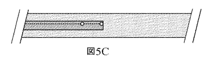
図5A〜5Eおよび図6A〜6Eは、血管カテーテルナビゲーション機器のいくつかの例示的な実施形態を示す。図5Aは、センサー302がカテーテル先端部にある実施形態を示す。図5Bは、センサーがカテーテル先端部ではなく、そこの近くにある実施形態を示す。この構成は、カテーテル先端部から媒質を導入する際にセンサーがパラメータを測定するのを防止し、流れの方向をより良好に区別できるようにし得る。図5Cは、2つのセンサーを備え、1つはカテーテル先端部にあり、および1つは、カテーテル先端部ではなく、そこの近くにある実施形態を示す。異なる位置でのセンサー読取値は、流体の流れの方向、特徴、プロファイルなどによって変わり得る。カテーテル先端部ではなく、そこの近くにあるセンサーは、先端部から約0.05cm〜約2.0cm戻ったところにあり得る。あるいは、カテーテル先端部ではなく、そこの近くにあるセンサーは、先端部から約0.75cm〜約1.25cm戻ったところにあり得る。図5Dは、センサーがガイドワイヤまたはスタイレット502上にある実施形態を示す。スタイレット502は、カテーテル内で自由に動いて、1つ以上のセンサーをカテーテル先端部から、ある距離に設置できるようにし得る。さらに、ガイドワイヤ/スタイレットは、カテーテルの設置後に除去され得る。この実施形態では、カテーテルはまた、ここで示すように、センサーを含み得る。図5Eは、開口部504がカテーテル先端部ではなく、そこの近くにある実施形態を示す。この開口部は、別個の媒質導入ルーメンまたは輸液ルーメンと流体連通し得る。この特定の媒質導入ルーメンは、カテーテル先端部で出てもよい。カテーテル先端部ではなく、そこの近くにある開口部は、先端部から約0.5cm〜約2.0cm戻ったところにあり得る。あるいは、カテーテル先端部ではなく、そこの近くにある開口部は、先端部から約0.75cm〜約1.25cm戻ったところにあり得る。媒質導入ルーメンは、カテーテル内にあっても、またはスタイレット内にあってもよい。
5A-5E and 6A-6E show some exemplary embodiments of vascular catheter navigation equipment. FIG. 5A shows an embodiment in which the
図6Aは、2つのセンサー間に開口部があり、両センサーは、カテーテル先端部ではなく、そこの近くにある実施形態を示す。図6Bは、2つ以上のセンサーがカテーテルの先端部ではなく、そこの近くにある実施形態を示す。図6Cは、2つのセンサー間に開口部を備え、センサーの一方がカテーテル先端部にある実施形態を示す。図6Dは、2つのセンサーに近接して開口部を含む実施形態を示す。図6Eは、チャンネル602を備える実施形態を示す。チャンネル602は、流体がカテーテル内を、カテーテル内のセンサーに近接して流れることができるようにする。
FIG. 6A shows an embodiment in which there is an opening between the two sensors, both sensors not at the tip of the catheter but near it. FIG. 6B shows an embodiment in which two or more sensors are located near the tip of the catheter rather than at the tip of the catheter. FIG. 6C shows an embodiment having an opening between the two sensors, one of which is at the tip of the catheter. FIG. 6D shows an embodiment that includes an opening in close proximity to the two sensors. FIG. 6E shows an embodiment including a
血管カテーテルナビゲーション機器のこれらおよび他の実施形態の多数の変形例が想定されることは明らかである。例えば、センサー、開口部、チャンネルなどは、カテーテルおよび/またはガイドワイヤ/スタイレットの異なる側面にあってもよい。センサー、開口部およびチャンネルは、ここでは、カテーテル先端部にあるまたはその近くにあると示しているが、それらは、カテーテルおよび/またはガイドワイヤ/スタイレットに沿ったいずれの箇所に置かれてもよい。 It is clear that numerous variations of these and other embodiments of the vascular catheter navigation device are envisioned. For example, sensors, openings, channels, etc. may be on different sides of the catheter and / or guidewire / stylet. Sensors, openings and channels are indicated here at or near the tip of the catheter, but they may be placed anywhere along the catheter and / or guidewire / stylet. Good.
図7Aは、血管カテーテルナビゲーション機器の一実施形態を使用する、豚の血管系の様々な場所における、温度対時間のデータを示す。このデータを獲得するために使用される実施形態は、2つの温度センサー−機器の先端部に最も近かった遠位センサー(T1)(そのためこの場合、心臓に最も近い)、および近位センサー(T2)−を有した。温度対時間の曲線は、両センサーに関して、血管系内の異なる5か所、上大静脈、大静脈心房接合部(cavoatrial junction)、右心房、右心室、および下大静脈で示されている。最初の2か所、上大静脈および大静脈心房接合部は、血管カテーテルナビゲーション機器の正しい設置を表している。他の3か所は、機器の間違った設置を表している。右側3つの温度対時間の曲線(間違った設置を表す)のシグニチャーは、最初の2つの曲線(正しい設置またはほぼ正しい設置を表す)とは異なることに留意されたい。右側3つの曲線はまた、互いに差別化され得ることにも留意されたい。異なるセンサー構成は、異なる血管の場所において異なる曲線のシグニチャーを生じる。例えば、単一の温度センサーは、2つの温度センサーを備えるシステムとは異なる組の曲線を与える。輸液出口部位からのセンサーの距離も、異なる曲線を提供する。異なる輸液流量(infusion rates)、輸液量、輸液タイプ(ボーラス対ストリーム)、輸液圧力、輸液速度(infusion velocities)なども、異なる曲線、それゆえ異なる解剖学的特徴を提供する。曲線の異なる局面がコントローラによって分析されて、血管の場所を決定し得る。これらは、限定されるものではないが、傾斜、大きさ、値、長さ、ばらつき、標準偏差、形状、曲線の下側の領域、フーリエ変換、周波数、高調波などを含み得る。いくつかの実施形態では、心拍、システム雑音などに関するものを含む、データ中のいくつかの周波数が、除去され得る。 FIG. 7A shows temperature vs. time data at various locations in the porcine vascular system using one embodiment of a vascular catheter navigation device. The embodiments used to obtain this data are two temperature sensors-the distal sensor (T1) closest to the tip of the device (hence the closest to the heart in this case), and the proximal sensor (T2). )-Has. Temperature-to-time curves are shown for both sensors at five different locations within the vasculature: the superior vena cava, the cavoatrial junction, the right atrium, the right ventricle, and the inferior vena cava. The first two locations, the superior vena cava and the vena cava atrial junction, represent the correct placement of the vascular catheter navigation device. The other three points represent the incorrect installation of the equipment. Note that the signatures of the three temperature-to-time curves on the right (representing the wrong installation) are different from the first two curves (representing the correct or near-correct installation). It should also be noted that the three curves on the right can also be differentiated from each other. Different sensor configurations produce different curved signatures at different vascular locations. For example, a single temperature sensor provides a different set of curves than a system with two temperature sensors. The distance of the sensor from the infusion outlet site also provides a different curve. Different infusion rates, infusion volumes, infusion types (bolus vs. stream), infusion pressure, infusion velocities, etc. also provide different curves and therefore different anatomical features. Different aspects of the curve can be analyzed by the controller to determine the location of blood vessels. These may include, but are not limited to, slopes, magnitudes, values, lengths, variability, standard deviations, shapes, lower regions of curves, Fourier transforms, frequencies, harmonics and the like. In some embodiments, some frequencies in the data may be eliminated, including those relating to heart rate, system noise, and the like.
いくつかの実施形態では、1つの温度センサーがあるため、1つの温度対時間の曲線がある。いくつかの実施形態では、2つ以上の温度センサーがあるため、2つ以上の温度対時間の曲線がある。2つの温度センサーのグラフが図7Aに示されている。いくつかの実施形態では、輸液出口ポートは、より近位の1つまたは複数の温度センサーの近くにある。いくつかの実施形態では、輸液出口ポートは、1つまたは複数の温度センサーよりも近位または遠位にある。いくつかの実施形態では、輸液出口ポートは温度センサー間にある。いくつかの実施形態では、1つまたは3つ以上の温度センサーを使用してもよい。 In some embodiments, there is one temperature vs. time curve because there is one temperature sensor. In some embodiments, there are two or more temperature vs. time curves because there are two or more temperature sensors. Graphs of the two temperature sensors are shown in FIG. 7A. In some embodiments, the infusion outlet port is closer to one or more temperature sensors more proximal. In some embodiments, the infusion outlet port is proximal or distal to one or more temperature sensors. In some embodiments, the infusion port is between the temperature sensors. In some embodiments, one or more temperature sensors may be used.
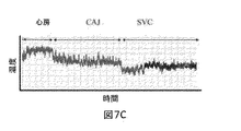
図7Bおよび図7Cは、2つの代替的な温度対時間の曲線を示す。曲線は、異なる解剖学的構造では、および血管カテーテルナビゲーション機器の設計に基づいて、異なって見えるかもしれないことに留意されたい。例えば、曲線は、流体出口ポートに対して異なるセンサーの場所では、異なり得る。曲線は、センサーのタイプまたは流体注入速度に依存し得る。曲線は、注入流体の初期温度に依存し得る。他の設計要因も、異なる温度対時間の曲線の形状となり得る。 7B and 7C show two alternative temperature vs. time curves. Note that the curves may look different in different anatomical structures and based on the design of the vascular catheter navigation device. For example, the curve can be different at different sensor locations with respect to the fluid outlet port. The curve may depend on the type of sensor or fluid injection rate. The curve may depend on the initial temperature of the injected fluid. Other design factors can also have different temperature vs. time curves.
さらに、温度対時間の曲線の較正は、コントローラによって実施され得る。例えば、基準測定は、システムの挿入後、またはシステムの使用中の他の時点で導き出され得る。例えば、基準測定は、いずれかの注入流体が注入される前に、または特定の注入速度で、血管において行われ得る。この例は図7Bに示されている。「基準」データはグラフに示されており、ここでは、温度測定は、システムによっていずれの流体も注入されずに行われた。この基準測定は、解剖学的構造内での血管カテーテルナビゲーション機器の場所を決定するために、コントローラのデータの分析において使用され得る。 In addition, temperature-to-time curve calibration can be performed by the controller. For example, reference measurements can be derived after insertion of the system or at other times during use of the system. For example, reference measurements can be made in a vessel before any infusion fluid is infused or at a particular infusion rate. An example of this is shown in FIG. 7B. The "reference" data are shown in the graph, where the temperature measurements were taken by the system without injecting any fluid. This reference measurement can be used in the analysis of controller data to determine the location of the vascular catheter navigation device within the anatomy.
温度対時間の曲線の様々な特性が、血管カテーテルナビゲーション機器の場所を決定するために、分析され得る。例えば、1つ以上の曲線の曲線振幅、雑音、標準偏差、形状、傾斜、値、曲線の下側の領域、フーリエ変換、周波数、高調波などが、血管系内での血管カテーテルナビゲーション機器の場所を決定するために、使用され得る。これらの同じパラメータが、複数の温度対時間の曲線間で比較されて、血管カテーテルナビゲーション機器の設置場所を決定し得る。例えば、曲線の位置、相対的位置、大きさ、および/またはピークの相対的な大きさ(正または負)が、血管カテーテルナビゲーション機器の場所を決定するために、使用され得る。さらに、複数の温度センサーからのデータの振幅、雑音、標準偏差、形状、傾斜、値、曲線の下側の領域、および/またはフーリエ変換、高調波、周波数間の差を使用して、血管の場所を決定し得る。液滴サイズおよび/または輸液流量に依存して、曲線の下側の領域またはフーリエ変換を使用して、温度対時間の曲線、それゆえ血管の場所を分析し得る。さらに、最大値、またはいくつもの最大値が、より意味があるとし得る。 Various properties of the temperature vs. time curve can be analyzed to determine the location of the vascular catheter navigation device. For example, the curve amplitude, noise, standard deviation, shape, slope, value, lower region of a curve, Fourier transform, frequency, harmonics, etc. of one or more curves are the locations of vascular catheter navigation devices within the vascular system. Can be used to determine. These same parameters can be compared across multiple temperature vs. time curves to determine the location of the vascular catheter navigation device. For example, the position of the curve, the relative position, the size, and / or the relative size of the peak (positive or negative) can be used to determine the location of the vascular catheter navigation device. In addition, the amplitude, noise, standard deviation, shape, slope, value, lower region of the curve, and / or Fourier transform, harmonics, and frequency differences of the data from multiple temperature sensors are used to make the vessel The location can be decided. Depending on the droplet size and / or fluid flow rate, the lower region of the curve or the Fourier transform can be used to analyze the temperature-to-time curve and hence the location of blood vessels. Moreover, the maximum value, or a number of maximum values, may be more meaningful.
本明細書では、用語「液滴」は、注入液に言及するときの、滴、ボーラス、ストリーム、間欠的なストリームなどを意味し得る。 As used herein, the term "droplet" can mean a drop, bolus, stream, intermittent stream, etc. when referring to an injectate.
図8は、所望の(正しい)および望ましくない(間違った)機器の設置を表す、血管系の異なる領域における流体の流れを示す概略図である。矢印802は血流方向を示す。領域804は、流体(食塩水など)の輸液を示す。異なる解剖学的な場所がどのように流体輸液の異なる流動状態、それゆえ異なる散逸パターンを生じるかに留意されたい。ここでは1つの温度センサー806を示すが、本明細書で開示するこのおよび任意の他の実施形態においては、2個、または3個、または4個または5個または6個またはそれよりも多いセンサーが使用されてもよい。
FIG. 8 is a schematic diagram showing fluid flow in different regions of the vascular system, representing the installation of desired (correct) and undesired (wrong) equipment.
図9A〜9Eは、2つの温度センサーがガイドワイヤ/スタイレット上にある、血管カテーテルナビゲーション機器の様々な実施形態を示す。図9Aは、近位温度センサー902および遠位温度センサー904を備えるスタイレット910を示す。この実施形態では、注入液906は、近位温度センサー902の近位にあるまたはそれに近いカテーテル908の遠位先端部で流出する。あるいは、注入液は、ガイドワイヤ/スタイレットのルーメンを通して注入され得る。ここでは2つのセンサーを示すが、1つ、または3つ以上のセンサーも使用され得る。
9A-9E show various embodiments of a vascular catheter navigation device with two temperature sensors on a guidewire / stylet. FIG. 9A shows a
図9Bは、注入液がスタイレット/ガイドワイヤを通して注入され、かつ2つの温度センサー間で流出する実施形態を示す。図9Cは、注入液がスタイレット/ガイドワイヤを通して注入され、かつ遠位温度センサーの近くまたはそれよりも遠位で流出する実施形態を示す。1つの温度センサーが使用される場合、流体注入出口ポートは、センサーよりも近位、または遠位のいずれかにあるとし得る。 FIG. 9B shows an embodiment in which the injectate is injected through the stylet / guide wire and flows out between the two temperature sensors. FIG. 9C shows an embodiment in which the infusion solution is injected through a stylet / guide wire and drains near or further distal to the distal temperature sensor. If one temperature sensor is used, the fluid inlet port may be either proximal or distal to the sensor.
図9Dおよび図9Eは、スタイレット/ガイドワイヤ上に2つの温度センサーがあり、ガイドワイヤが、カテーテルの端部に対して動かされることができる実施形態を示す。この実施形態は、感知および/またはカテーテルの先端部に対する注入液出口の場所を変更するために使用され得る。 9D and 9E show an embodiment in which there are two temperature sensors on the stylet / guide wire and the guide wire can be moved relative to the end of the catheter. This embodiment can be used to change the location of the infusion outlet relative to the sensing and / or the tip of the catheter.
例えば、いくつかの実施形態では、スタイレット/ガイドワイヤは、注入ルーメン(すなわちスタイレット/ガイドワイヤは中空とし得る)および温度センサーの双方を含み得るため、解剖学的構造内に最初におよび/または血管カテーテルとは無関係に位置決めされ得る。例えば頸静脈アクセスがカテーテル挿入に使用されるとき。ひとたびスタイレット/ガイドワイヤが設置されたら、血管カテーテルは前進され得るため、カテーテルの遠位先端部は、スタイレット/ガイドワイヤの遠位先端部に対して公知の位置にある。その後、スタイレット/ガイドワイヤは除去され得る。 For example, in some embodiments, the stylet / guidewire can include both an infusion lumen (ie, the stylet / guidewire can be hollow) and a temperature sensor, so that it is first and / or in the anatomy. Alternatively, it can be positioned independently of the vascular catheter. For example when jugular vein access is used for catheter insertion. The distal tip of the catheter is in a known position with respect to the distal tip of the stylet / guidewire so that the vascular catheter can be advanced once the stylet / guidewire is installed. The stylet / guide wire can then be removed.
図9F〜9Hは、流体出口ポートと温度センサーとの間の距離、およびカテーテル/スタイレット先端部とセンサー/ポートとの間の距離を示す。図9Fは、注入液出口またはポートと、遠位または単一の温度センサーとの間の軸方向距離aaを示す。軸方向距離bbは、流体出口ポートと近位温度センサーとの間の距離である。軸方向距離ccは、遠位温度センサーと近位温度センサーとの間の距離である。これらの距離は、正でもまたは負でもよい。ここでは2つの温度センサーを示すが、機器は、1つのセンサーまたは3つ以上のセンサーを有してもよい。 9F-9H show the distance between the fluid outlet port and the temperature sensor, and the distance between the catheter / stylet tip and the sensor / port. FIG. 9F shows the axial distance aa between the infusion outlet or port and the distal or single temperature sensor. The axial distance bb is the distance between the fluid outlet port and the proximal temperature sensor. The axial distance cc is the distance between the distal temperature sensor and the proximal temperature sensor. These distances can be positive or negative. Although two temperature sensors are shown here, the device may have one sensor or three or more sensors.
距離aaは約0mmとし得る。あるいは、距離aaは、約0mm〜約0.5mm、または約0mm〜約1mmの範囲にあるとし得る。あるいは、距離aaは約0mm〜約2mmの範囲にあるとし得る。あるいは、距離aaは約0mm〜約3mmの範囲にあるとし得る。あるいは、距離aaは約3mm〜約5mmとし得る。あるいは、距離aaは約5mm〜約10mmとし得る。あるいは、距離aaは約0mm〜約100mmの範囲にあるとし得る。あるいは、これらの距離は負でもよい。例えば、距離aaは、約1mmとしても、または約−1mmとしてもよい。1mmの場合、遠位温度センサーは、流体出口ポートよりも遠位にある。−1mmの場合、流体出口ポートは、遠位温度センサーよりも遠位にある。これは、図9F〜9Hに関連して提供されるあらゆる寸法において真である。 The distance aa can be about 0 mm. Alternatively, the distance aa may be in the range of about 0 mm to about 0.5 mm, or about 0 mm to about 1 mm. Alternatively, the distance aa may be in the range of about 0 mm to about 2 mm. Alternatively, the distance aa may be in the range of about 0 mm to about 3 mm. Alternatively, the distance aa can be from about 3 mm to about 5 mm. Alternatively, the distance aa can be from about 5 mm to about 10 mm. Alternatively, the distance aa may be in the range of about 0 mm to about 100 mm. Alternatively, these distances may be negative. For example, the distance aa may be about 1 mm or about -1 mm. At 1 mm, the distal temperature sensor is distal to the fluid outlet port. At -1 mm, the fluid outlet port is distal to the distal temperature sensor. This is true in all the dimensions provided in connection with FIGS. 9F-9H.
距離bbは約10mmとし得る。あるいは、距離bbは約0mm〜約10mmの範囲にあるとし得る。あるいは、距離bbは約8mm〜約12mmの範囲にあるとし得る。あるいは、距離bbは約5mm〜約15mmの範囲にあるとし得る。あるいは、距離bbは約1mm〜約100mmの範囲にあるとし得る。あるいは、距離bbは約3mm〜約5mmとし得る。あるいは、距離bbは約5mm〜約10mmとし得る。あるいは、距離bbは約0mm〜約100mmの範囲にあるとし得る。これらの範囲も負の距離としてもよい。 The distance bb can be about 10 mm. Alternatively, the distance bb may be in the range of about 0 mm to about 10 mm. Alternatively, the distance bb may be in the range of about 8 mm to about 12 mm. Alternatively, the distance bb may be in the range of about 5 mm to about 15 mm. Alternatively, the distance bb may be in the range of about 1 mm to about 100 mm. Alternatively, the distance bb can be from about 3 mm to about 5 mm. Alternatively, the distance bb can be from about 5 mm to about 10 mm. Alternatively, the distance bb may be in the range of about 0 mm to about 100 mm. These ranges may also be negative distances.
距離ccは約10mmとし得る。あるいは、距離ccは約0.0mm〜約5mmの範囲にあるとしても、あるいは、距離ccは約5mm〜約15mmの範囲にあるとしてもよい。あるいは、距離ccは約15mm〜約20mmの範囲にあるとし得る。あるいは、距離ccは約1mm〜約100mmの範囲にあるとし得る。 The distance cc can be about 10 mm. Alternatively, the distance cc may be in the range of about 0.0 mm to about 5 mm, or the distance cc may be in the range of about 5 mm to about 15 mm. Alternatively, the distance cc may be in the range of about 15 mm to about 20 mm. Alternatively, the distance cc may be in the range of about 1 mm to about 100 mm.
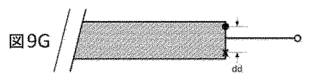
図9Gの距離ddは、流体出口ポートと、遠位温度センサーまたは近位温度センサーのいずれかとの間の距離である。距離は、ここでは近位温度センサーに対して示されるが、距離ddはいずれかに適用され得る。あるいは、温度センサーは1つのみ存在し得る。距離ddは約0.75mmとし得る。あるいは、距離ddは約0.25mm〜1.5mmの範囲にあるとし得る。あるいは、距離ddは約0.1mm〜5mmの範囲にあるとし得る。 The distance dd in FIG. 9G is the distance between the fluid outlet port and either the distal temperature sensor or the proximal temperature sensor. The distance is shown here for the proximal temperature sensor, but the distance dd can be applied to either. Alternatively, there may be only one temperature sensor. The distance dd can be about 0.75 mm. Alternatively, the distance dd may be in the range of about 0.25 mm to 1.5 mm. Alternatively, the distance dd may be in the range of about 0.1 mm to 5 mm.
図9Hは、流体出口ポートとカテーテルおよび/またはスタイレットの端部との間の軸方向距離eeを示す。距離eeは約0mmとし得る。あるいは、距離eeは約0mm〜約1mmの範囲にあるとし得る。あるいは、距離eeは約0mm〜約3mmの範囲にあるとし得る。あるいは、距離eeは約0mm〜約5mmの範囲にあるとし得る。あるいは、距離eeは約5mm〜約10mmの範囲にあるとし得る。あるいは、距離eeは約0mm〜約100mmの範囲にあるとし得る。これらの距離は正でもまたは負でもよい。 FIG. 9H shows the axial distance ee between the fluid outlet port and the end of the catheter and / or stylet. The distance ee can be about 0 mm. Alternatively, the distance ee may be in the range of about 0 mm to about 1 mm. Alternatively, the distance ee may be in the range of about 0 mm to about 3 mm. Alternatively, the distance ee may be in the range of about 0 mm to about 5 mm. Alternatively, the distance ee may be in the range of about 5 mm to about 10 mm. Alternatively, the distance ee may be in the range of about 0 mm to about 100 mm. These distances can be positive or negative.
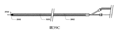
図9Iは、センサーを1つのみ含みかつシステム内に導管912を含む、血管カテーテルナビゲーション機器の実施形態を示す。導管を含むシステムの様々な実施形態は、本明細書の他の箇所でより詳細に説明する。導管912は、Xで示す注入液出口ポートを組み込む。ここで示す距離ffは、導管の流体状注入液出口ポートとセンサーとの間の長手方向距離である。
FIG. 9I shows an embodiment of a vascular catheter navigation device that includes only one sensor and a
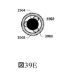
図9Jは、図9Iのものと同様の、距離ggが導管の流体状注入液出口ポートとセンサーとの間の半径方向距離を表す実施形態を示す。 FIG. 9J shows an embodiment similar to that of FIG. 9I, in which the distance gg represents the radial distance between the fluid inlet port of the conduit and the sensor.
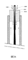
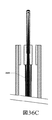
図10は、任意のカテーテルと一緒に使用され得る、または換言すると、温度センサー、注入液ルーメン、コントローラ、およびロッキング機構がスタイレット/ガイドワイヤに含まれる、血管カテーテルナビゲーション機器の実施形態を示す。図10は、2つの熱電対、遠位熱電対1012および近位熱電対1010、およびガイドワイヤ/スタイレット1001の一部として注入液出口ポート1002を備える実施形態を示す。あるいは、スタイレット/ガイドワイヤは、1つの温度センサーしか有しなくてもよく、または3つ以上の温度センサーを有してもよい。スタイレット/ガイドワイヤは、スタイレット/ガイドワイヤとカテーテルを位置合わせするのを支援するための特徴1014を含み得る。この実施形態は、温度センサーを埋め込むために、先端部分1006、例えば成形されたウレタン、ナイロン、シリコーン、または他のポリマー部分を含み得る。同様にここに、任意選択的なガイドワイヤ/スタイレットコイル1008、およびカテーテル1018の遠位先端部を示す。断面図では、注入ルーメン1016も示され得る。
FIG. 10 shows an embodiment of a vascular catheter navigation device that can be used with any catheter, or in other words, includes a temperature sensor, infusion lumen, controller, and locking mechanism in the stylet / guidewire. FIG. 10 shows an embodiment comprising two thermocouples, a
この実施形態はトルクまたはロッキング機器1022を含み得、トルクまたはロッキング機器は、例えばカテーテル1018の近位端部にあるルアーロック1020を使用して、スタイレットをカテーテルの近位端部にロックするために使用され得る。トルク/ロッキング機器はスタイレット/ガイドワイヤにロックされるため、スタイレット/ガイドワイヤは血管カテーテルに対して動かない。コントローラ(図示せず)は、輸液機構を含みおよび/または流体ポート1026を介してそれを制御し、ならびに温度ポート1004を介して温度センサーからのデータを読み取り得る。コントローラは、スタイレットの近位端部の近くに置かれてもよいし、またはスタイレットの近位端部から数インチまたは数フィートに置かれてもよい。温度センサーリード線1024も示されている。輸液は、定常でも、または間欠的でも、またはボーラスからなってもよい。
This embodiment may include a torque or locking
図11A〜Iは、血管カテーテルナビゲーション機器のスタイレット/ガイドワイヤのバージョンの様々な実施形態の様々な図を示す。 11A-I show different diagrams of different embodiments of stylet / guidewire versions of vascular catheter navigation equipment.
11A〜11Iおよびいくつかの他の実施形態に示すスタイレットは:1)挿入を支援するためのカテーテルの補剛、2)流体送給のための媒質の提供、および3)1つまたは複数の温度センサーの配線のためのチャンネルの提供を含む、いくつかの機能を果たす。図11Aは、図10の実施形態に示すものなどのスタイレットの断面である。ここでは2つの温度センサーを示すが、機器は、1つ、または3つ以上のセンサーを含んでもよい。 The stylets shown in 11A-11I and some other embodiments are: 1) stiffening the catheter to assist insertion, 2) providing a medium for fluid delivery, and 3) one or more. It serves several functions, including providing channels for wiring the temperature sensor. FIG. 11A is a cross section of a stylet such as that shown in the embodiment of FIG. Although two temperature sensors are shown here, the device may include one or more sensors.
図11Bは、トリプルルーメンの熱収縮および/またはチューブのハウジング1102に3つの構成要素を含むスタイレットの実施形態を示し、そこに、2つの温度センサー1104および流体ルーメン1016を入れている。あるいは、1つまたは3つ以上の温度センサーが存在してもよい。
FIG. 11B shows an embodiment of a stylet that includes three components in a triple lumen heat shrink and / or
図11Cは、スタイレットコイルの全て、または一部が、温度センサーワイヤから作製される実施形態を示す。図11Dは、図11Cに示す実施形態の側面図である。 FIG. 11C shows an embodiment in which all or part of the stylet coil is made from temperature sensor wires. FIG. 11D is a side view of the embodiment shown in FIG. 11C.
図11Eは、2つの温度センサーならびに流体ルーメンを収納する押出品、すなわちチューブ(金属またはプラスチック)を含む実施形態を示す。あるいは、1つまたは3つ以上の温度センサーが存在してもよい。 FIG. 11E shows an embodiment comprising two temperature sensors and an extruded product containing a fluid lumen, i.e. a tube (metal or plastic). Alternatively, there may be one or more temperature sensors.
図11Fは、ひとまとめに束ねた複数の熱電対、ならびに流体ルーメンを収納する押出品、すなわちチューブ(金属またはプラスチック)を含む実施形態を示す。 FIG. 11F shows an embodiment that includes a plurality of thermocouples bundled together and an extruded product, that is, a tube (metal or plastic) that houses a fluid lumen.
図11Gは、温度センサーが流体ルーメンによって囲まれている、薄壁の押出品、すなわちチューブを含む実施形態を示す。1つ、2つ、または3つ以上の温度センサーが存在してもよい。 FIG. 11G shows an embodiment comprising a thin-walled extruded product, i.e. a tube, in which the temperature sensor is surrounded by fluid lumens. There may be one, two, or three or more temperature sensors.
図11Hは、複数の温度センサー、流体ルーメン、ならびにワイヤやロッドとし得る補剛材1108を含む、押出品、すなわちチューブ(プラスチックまたは金属)を含む実施形態を示す。1つ、2つ、または3つ以上の温度センサーが存在してもよい。
FIG. 11H shows an embodiment comprising an extruded product, i.e. a tube (plastic or metal), comprising a plurality of temperature sensors, fluid lumens, and
図11Iは、温度センサー束ならびに流体ルーメンを含む、押出品、すなわちチューブ(プラスチックまたは金属)を含む実施形態を示す。温度センサー束の外面は、外側押出品と同様の材料で作製され、これにより、任意選択的な化学的にまたは熱で形成される接着または溶接1106を可能にし得る。1つ、2つ、または3つ以上の温度センサーが存在してもよい。
FIG. 11I shows an embodiment comprising an extruded product, i.e. a tube (plastic or metal), comprising a bundle of temperature sensors and a fluid lumen. The outer surface of the temperature sensor bundle is made of a material similar to the outer extruded product, which may allow optional chemically or heat-formed adhesion or
いくつかの実施形態では、カテーテル先端部とガイドワイヤ/スタイレットとの間の距離を固定する、または正確に制御すること、またはカテーテル先端部とガイドワイヤ/スタイレットとの間の距離を決定できるようにすることのいずれかが重要である。温度センサーに対する注入の場所を固定できるようにすること、または注入出口ポートの場所と温度センサーとの間の距離を知ることができるようにすることも重要とし得る。出口ポートと温度センサーとの間の距離は、流体輸液の期間中の温度プロファイルに対する影響を有し得る。これらの距離は、複数の患者およびシナリオで固定されても、または異なる患者のタイプおよび異なるシナリオに対して異なってもよい。例えば、距離は、アクセス中の血管系に依存して異なってもよい。距離は、異なる重量、サイズ、体重指数、健康状態、年齢、性別、心臓の症状(heart condition)、または他の患者特性を有する患者に対して異なってもよい。距離は、ルーメンの数および形状が異なるカテーテルなど、異なるカテーテルサイズに対して異なってもよい。 In some embodiments, the distance between the catheter tip and the guidewire / stylet can be fixed or precisely controlled, or the distance between the catheter tip and the guidewire / stylet can be determined. It is important to do either. It may also be important to be able to fix the location of the injection to the temperature sensor, or to be able to know the distance between the location of the injection outlet port and the temperature sensor. The distance between the outlet port and the temperature sensor can have an effect on the temperature profile during the period of fluid infusion. These distances may be fixed for multiple patients and scenarios, or may differ for different patient types and different scenarios. For example, the distance may vary depending on the vascular system being accessed. Distance may vary for patients with different weight, size, body mass index, health status, age, gender, heart condition, or other patient characteristics. The distance may be different for different catheter sizes, such as catheters with different numbers and shapes of lumens.
いくつかの実施形態では、スタイレット/ガイドワイヤは、図10に示すようなカテーテルの近位端部の近くにあるトルク機器を使用して、カテーテル先端部に対して固定またはロックされる。 In some embodiments, the stylet / guidewire is secured or locked to the catheter tip using a torque device located near the proximal end of the catheter as shown in FIG.
いくつかの実施形態では、ユーザは、目で確認することによって、カテーテルとスタイレット/ガイドワイヤとの相対的な位置合わせを決定してから、2つの値から相対距離を測定する。 In some embodiments, the user determines the relative alignment of the catheter with the stylet / guidewire by visual inspection and then measures the relative distance from the two values.
図12〜17は、スタイレット上の1つまたは複数の温度センサーと、カテーテル先端部または流体注入点との間の距離を固定するか、または知るための、様々な登録技術を含む血管カテーテルナビゲーション機器の様々な実施形態を示す。 Figures 12-17 are vascular catheter navigation including various registration techniques for fixing or knowing the distance between one or more temperature sensors on the stylet and the catheter tip or fluid injection point. Various embodiments of the device are shown.
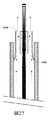
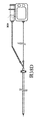
図12は、温度センサーから固定された公知の距離に、スタイレット/ガイドワイヤ上にインジケータを備える実施形態を示す。この実施形態では、ユーザは、患者に挿入する前に、カテーテル1202の先端部と、スタイレット1206上のインジケータ、すなわち印1204を位置合わせする。スタイレットの先端部に対するカテーテル先端部の相対距離1208は、カテーテルが患者に挿入される前に、好ましくは近位端部において、トルク機器、ロッキング・ローテーティング(locking rotating)止血弁、トゥーイ・ボースト(tuohy−borst)弁、または他のロッキング機構を使用してロックされ得る。ガイドワイヤ/スタイレット上のインジケータは、可視的な印、例えば赤色のストライプまたはドット、または触覚的な印、例えば突起や溝、または他のタイプのインジケータとし得る。
FIG. 12 shows an embodiment in which an indicator is provided on the stylet / guidewire at a known distance fixed from the temperature sensor. In this embodiment, the user aligns the tip of
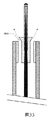
図13は、遠位温度センサーから固定された公知の距離に、スタイレット上に隆起部、または突起1302を備える実施形態を示す。これにより、ユーザは、可視的に、または手触りによってのいずれかで、カテーテルの先端部をスタイレット上の突起と位置合わせすることができる。この位置合わせは、体外または体内で行われ得る。いくつかの実施形態では、突起は、解剖学的構造内に設置した後でスタイレットがカテーテルから除去され得るように、十分に小さいかまたは柔らかい。
FIG. 13 shows an embodiment in which a ridge or
図14は、図13に示すものと同様の、温度センサー1104がスタイレット上の突起の機能を果たす実施形態を示す。
FIG. 14 shows an embodiment in which the
図15は、治具、またはブロック、またはアライナー1502を使用して、カテーテルの先端部を、スタイレットの先端部から固定された公知の距離に位置合わせする実施形態を示す。そのため、スタイレットに対するカテーテルの相対的位置は、トルク機器、ロッキング・ローテーティング止血弁、トゥーイ・ボースト弁、または他のロッキング機構を使用して近位端部において、および/または固定式導管(本明細書の他の箇所で詳細に開示する)を使用して遠位端部において、またはそれら双方で、ロックされる。治具またはブロック1502は、それ自体、調整可能とし得るため、流体出口ポート(ここではカテーテルの遠位端部)を様々な異なる長さで温度センサーと位置合わせできる。
FIG. 15 shows an embodiment in which a jig, block, or
図16は、可膨張性のバルーン1602を突起として使用して、カテーテルとスタイレットを位置合わせする、図13に示すものと同様の実施形態を示す。バルーンは、環状としてもよいし、またはスタイレットの1つ以上の側面上にあってもよい。バルーンは、位置合わせの際に使用するために膨張され、および設置の期間中に膨張されたままにされて、カテーテルに対してスタイレットを適所にロックするか、または設置の期間中にしぼまされる(カテーテルおよびスタイレットが、トルクまたは弁を使用して互いにロックされる箇所)かのいずれかとし得る。この実施形態では、スタイレットまたはカテーテルは膨張ルーメンを含み、バルーンを膨張させ、かつしぼませる。バルーンは、カテーテルの設置後にスタイレットを除去するために、しぼまされ得る。
FIG. 16 shows an embodiment similar to that shown in FIG. 13 in which an
図17は、使用中にカテーテル先端部の内側にあるときを感知し得るセンサー1702を含む、血管カテーテルナビゲーション機器の実施形態を示す。例えば、センサーは、磁気、超音波、光、温度などとし得る。いくつかの実施形態では、近位温度センサー1704は、近位温度センサーがカテーテル先端部の内側にあるときを決定するセンサーとして使用される。注入液の注入後の温度対時間の曲線の形状は、温度センサーがカテーテル先端部のすぐ内側にあるときの特定のプロファイルを示し、およびこの位置合わせを特定するために使用され得る。この実施形態は、1つ、2つ、またはそれよりも多い温度センサーを含み得る。
FIG. 17 shows an embodiment of a vascular catheter navigation device that includes a
いくつかの実施形態では、注入液出口のフローパターンの制御が、一貫した結果を達成するために、重要とし得る。注入液の流れを、血管系/心臓内の血流の流れと対比することも重要とし得る。注入液の流れは、これらの目標を達成するために、より層流またはより乱流のいずれかに意図的にされ得る。いくつかの実施形態は、流れを方向付けかつカテーテルまたはスタイレットの一部である特徴を含み得る。これらの特徴は、ディンプリング、またはカテーテルまたはスタイレットの表面仕上げを変化させるオレンジピール仕上げのような表面特徴とし得る。これらの特徴は、スタイレット/温度センサーのODの一部、または流体ルーメンのID、またはそれら双方とし得る。 In some embodiments, control of the flow pattern at the infusion outlet may be important to achieve consistent results. It may also be important to contrast the flow of infusions with the flow of blood flow in the vascular system / heart. The infusion flow can be deliberately either more laminar or more turbulent to achieve these goals. Some embodiments may include features that direct the flow and are part of a catheter or stylet. These features can be surface features such as dimple rings, or an orange peel finish that alters the surface finish of the catheter or stylet. These features can be part of the stylet / temperature sensor OD, or the fluid lumen ID, or both.
図18AおよびBは、血管カテーテルナビゲーション機器の注入液ルーメン1016にある、(層流または乱流の流れを生じるための)導流体(flow director)に対する2つの考えられる実施形態を示す。導流体1802は、図18Aに示すように、注入液ルーメンの端部にあってもよいし、または図18Bに示すように、ルーメン出口の先端部から奥まったところにあってもよい。
18A and 18B show two possible embodiments for a flow director (to create a laminar or turbulent flow) in the
図19A〜Cは、注入液ルーメンの形状が、ルーメンから流出する流体の流れのタイプを制御する、血管カテーテルナビゲーション機器の他の実施形態を示す。変更され得るパラメータのいくつかは、注入液ルーメンの開口部の面積、形状、表面状態などを含み得る。温度センサーおよび/または補剛材1902も示されている。
19A-C show another embodiment of a vascular catheter navigation device in which the shape of the infusion lumen controls the type of fluid flow out of the lumen. Some of the parameters that can be changed may include the area, shape, surface condition, etc. of the opening in the infusion lumen. Temperature sensors and / or
いくつかの実施形態は、スタイレットおよび/またはカテーテルを振動させて、注入液ルーメンから注入液の乱流を生じる。 In some embodiments, the stylet and / or catheter is vibrated to create turbulent infusion from the infusion lumen.
図20は、注入ルーメンのないスタイレットの実施形態を示す。流体は、カテーテル先端部の上流の、挿入部位により近い、またはどこか他の箇所にある、別のカテーテルルーメン(おそらくは、別個のカテーテル上にある)を通って導入され得る。例えば、流体は、ここでは、血管カテーテルと一緒に示される「相棒」カテーテル2002によって注入され得る。流体はまた、カテーテルまたは「相棒」カテーテル上にある加熱/冷却素子によって加熱または冷却され得る。輸液用の「相棒」ガイドワイヤ/スタイレットも想定される。
FIG. 20 shows an embodiment of a stylet without an infusion lumen. The fluid can be introduced through another catheter lumen (perhaps on a separate catheter) upstream of the catheter tip, closer to the insertion site, or elsewhere. For example, the fluid can be infused here by the "buddy"
図21は、乱流制御を強化する注入液ルーメン内の特徴2102を示す。
FIG. 21 shows a
図22は、層流(または乱流が少ない)制御を生じ得る注入液ルーメン内の特徴2202を示す。
FIG. 22 shows a
本明細書で開示するいくつかの実施形態は、2つのセンサーを示すことに留意されたい。これらの実施形態のいずれかでは、1つ、2つ、またはそれよりも多いセンサーが使用され得る。 It should be noted that some embodiments disclosed herein represent two sensors. In any of these embodiments, one, two, or more sensors may be used.
いくつかの実施形態では、スタイレットの外径(OD)は約1mm以下である。いくつかの実施形態では、スタイレットのODは約0.5mm以下である。いくつかの実施形態では、スタイレットのODは約1.5mm以下である。いくつかの実施形態では、スタイレットのODは約0.2mm〜約5mmの範囲内にあるとし得る。 In some embodiments, the stylet has an outer diameter (OD) of about 1 mm or less. In some embodiments, the stylet OD is about 0.5 mm or less. In some embodiments, the stylet has an OD of about 1.5 mm or less. In some embodiments, the stylet OD may be in the range of about 0.2 mm to about 5 mm.
カテーテルがダブルまたはトリプルルーメンであるいくつかの実施形態では、スタイレットの機能性は別々の部分に分割され(流体、補剛材、温度感知など)、および複数のスタイレットが、カテーテルの複数のルーメン内で使用され得る。 In some embodiments where the catheter is double or triple lumen, the functionality of the stylet is divided into separate parts (fluid, stiffener, temperature sensing, etc.), and the stylet is multiple of the catheter. Can be used within the lumen.
熱電対、光ファイバー、抵抗、バイメタル、温度計、状態変化、シリコンダイオード、サーミスタ、光学温度測定(赤外線または別の方法)、水銀温度計、圧力計などを含む、多くのタイプの温度センサーが、本明細書で開示する実施形態のいずれかにおいて使用され得る。 Many types of temperature sensors include thermocouples, optical fibers, resistors, bimetals, thermometers, state changes, silicon diodes, thermistors, optical temperature measurements (infrared or alternative), mercury thermometers, pressure gauges, etc. It can be used in any of the embodiments disclosed herein.
流体を輸液することに加え、本明細書の他の箇所で開示しているように、カテーテル/スタイレットの先端部でまたはその近くで熱変化を生じる他の方法が、使用され得る。体温よりも高い温度の流体が導入され得、抵抗加熱素子、または圧電冷却素子などが、カテーテル内、カテーテル上、ガイドワイヤ/スタイレット上、または注入器に、体外に、含まれ得る。あるいは、注入される流体は、体温とは異なるが、厳しく制御されてはいない温度にあるとしてもよく、および(体温と注入液の温度との間の)この温度差が、コントローラによって測定され、かつ追跡される。 In addition to infusing the fluid, other methods of producing thermal changes at or near the tip of the catheter / stylet, as disclosed elsewhere herein, may be used. A fluid having a temperature higher than the body temperature can be introduced, and a resistance heating element, a piezoelectric cooling element, or the like can be included in the catheter, on the catheter, on the guide wire / stylet, or in the injector, and outside the body. Alternatively, the infused fluid may be at a temperature that is different from body temperature but not tightly controlled, and this temperature difference (between body temperature and infusion temperature) is measured by the controller. And be tracked.
抵抗加熱素子を用いる実施形態では、抵抗加熱素子は、カテーテル上に、またはスタイレット上にあるとし得る。カテーテル上にある実施形態では、カテーテルの外部に、またはカテーテルの1つ以上のルーメン内にあるとし得る。あるいは、ガイドワイヤ/スタイレット上にあってもよい。ガイドワイヤ/スタイレット上にある実施形態では、カテーテルルーメン内に、部分的にカテーテルルーメン内に、または血液に曝されるカテーテルルーメンの外部にあってもよい。血液を加熱/冷却するとき、注入液の注入は必要とされないかもしれない。 In embodiments where the resistance heating element is used, the resistance heating element may be on the catheter or on the stylet. In embodiments that are on the catheter, it may be outside the catheter or within one or more lumens of the catheter. Alternatively, it may be on a guide wire / stylet. In embodiments that are on guidewires / stylets, they may be within the catheter lumen, partially within the catheter lumen, or outside the catheter lumen exposed to blood. Infusion of infusion may not be required when heating / cooling the blood.
図23A〜Eおよび図24A〜Eに示すように、グラフィカルユーザインターフェースが、小型スクリーン/ディスプレイ2314、大型スクリーン、投影の形態で、仮想現実または拡張現実ゴーグルなどで、表示され得る。ユーザインタラクションの主な分類は、ユーザ警報:1)アイコン、2)アイコンの色または警告灯、3)警報を伴う聴覚トーン、4)カテーテル先端部の場所に適合しかつ警報のタイプを用いる視覚的な身体マップ、5)ステータスまたは警報、振動などを示す、ディスプレイ上に書かれた語句または言葉のいずれかの組み合わせを有し得る。分類は、以下とし得る:1)「前進続行」、これは、カテーテル先端部が末梢静脈を通って前進していること、またはカーブを曲がって上大静脈に到達していることを意味する。このモードは、緑色の点灯および図像およびポジティブなトーンなどのポジティブな状態を示す視覚および聴覚フィードバックを伴う。2)チェックマーク図像を用いる「正しい設置」は、先端部が適切な場所−PICCラインに対しては大静脈心房接合部、または別のタイプのカテーテル挿入に関してはおそらくは別の場所に、到達したことを示す。この状態にも、ポジティブなトーンおよび点灯が伴い得る。3)カテーテルが、対向する流れに直面する場合、警告、「向きの変更」が現れ得る。これは、カテーテルが奇静脈枝を下方に前進する、IVC内へ前進する、または動脈内に設置された場合の警告である。これはポジティブな状態ではないため、この状態は、赤色、黄色またはオレンジ色の点灯または図像を、好ましくない状態が実施されていることを示すトーンと一緒に、伴い得る。不快な周波数、ピッチおよびトーンが伴い得る。4)カテーテルが心臓内に、心房または心室のいずれかにある場合、ユーザは、心臓のアイコンおよび/または「心臓内」の警告によって、注意喚起され得る。この状態にはネガティブな色およびトーンが伴い得る。5)カテーテル先端部が、静脈の壁に当たる場合、またはある種の障害物を有する場合、「調整」の警告が表示され得る。この状態にはネガティブな色およびトーンが伴い得る。また、図23A〜Eおよび図24A〜Eには、カテーテル2302、スタイレット2304、温度アダプター2306、流体アダプター2308、主ボタン2310、および挿入/追跡ボタン2312が示されている。
As shown in FIGS. 23A-E and 24A-E, the graphical user interface may be displayed in the form of a small screen /
グラフィカルユーザインターフェース(GUI)は、リアルタイムで、3次元空間に関するカテーテルの先端部の場所を表示し、それによってナビゲーションし得る。図23A〜Eおよび図24A〜Eに示すグラフィカルユーザインターフェースは2次元であるが、いくつかの実施形態は、3次元でも情報を通信し得る3次元ディスプレイを含む。 A graphical user interface (GUI) can display and navigate the location of the catheter tip in three-dimensional space in real time. The graphical user interfaces shown in FIGS. 23A-E and 24A-E are two-dimensional, but some embodiments include a three-dimensional display capable of communicating information in three dimensions as well.
本明細書で開示するいくつかの実施形態は、血管カテーテルにセンサーを組み込むが、血管カテーテルナビゲーション機器は、血管カテーテル内に収まり、かつひとたび血管カテーテルの設置が完了したら除去され得るスタンドアロン機器とし得ることに留意されたい。血管カテーテルナビゲーション機器は、例えば、標準的な血管カテーテルのスタイレットまたはガイドワイヤの機能を果たし得る。 Some embodiments disclosed herein incorporate a sensor in a vascular catheter, but the vascular catheter navigation device can be a stand-alone device that fits within the vascular catheter and can be removed once the vascular catheter installation is complete. Please note. The vascular catheter navigation device can, for example, function as a standard vascular catheter stylet or guide wire.
図25A〜Cは、機器の流体出口点から流出する流体の流れを制御するための導管を含む血管カテーテルナビゲーション機器の実施形態を示す。この実施形態では、導管2502は、ガイドワイヤ/スタイレット2504に取り付けられ、スタイラス/導管複合機器を形成する。導管2502は、血管カテーテル2508の輸液ルーメン2506のID内に収まるように設計される。この図面では、血管カテーテル2508のみが、1つのルーメン、輸液ルーメンを含むが、輸液ルーメンに加えて、複数のルーメンが血管カテーテル内に存在してもよい。
25A-C show embodiments of a vascular catheter navigation device that includes conduits for controlling the flow of fluid flowing out of the device's fluid outlet point. In this embodiment, the
いくつかの実施形態では、ガイドワイヤ/スタイレット2504は、コア2510、コイル2512、エンドキャップ2514および温度センサー2516を含む。コア2510は補剛ワイヤを含み得、補剛ワイヤは、テーパが付けられていてもよく、かつ温度センサーに至る。温度センサーは、エンドキャップに組み込まれても、または別個としてもよい。1つ以上の温度センサーが存在してもよい。温度センサーは熱電対とし得る。熱電対のより大きな断面寸法は温度測定値を減衰し、ここでは、熱電対のより小さな断面寸法は、より迅速な応答時間を可能にし得る。熱電対の直径または断面寸法2526は約0.2mm〜0.3mmとし得る。あるいは、熱電対の直径または断面寸法2526は約.02mm〜約.5mmとし得る。
In some embodiments, the guidewire /
いくつかの実施形態では、導管2502は、長さ2520を有し、および直径または断面寸法2522の1つまたは複数の流体流路2518を含む。流路は、断面形状が円形、または卵形、または任意の形状とし得る。流路は、直径または断面寸法が約0.4〜0.6mmとし得る。あるいは、流路は、直径または断面寸法が約0.1〜1.0mmとし得る。あるいは、流路は、直径または断面寸法が約0.01〜2.0mmとし得る。導管長2520は約4〜8mmとし得る。あるいは、導管長2520は約0.5mm〜20mmとし得る。
In some embodiments, the
流路の断面の面積および形状は、導管から流出する流速を決定する。流路の数も、導管から流出する流体のフローパラメータに影響を及ぼす。好ましくは、流体の輸液流量は約2〜3ml/分とし得る。あるいは、流体の輸液流量は約3〜5ml/分とし得る。あるいは、流体の輸液流量は約5〜10ml/分とし得る。あるいは、流体の輸液流量は約1〜5ml/分とし得る。導管出口の流速は、好ましくは、約60〜100cm/秒である。あるいは、導管出口の流速は約1〜300cm/秒である。 The area and shape of the cross section of the flow path determine the flow velocity out of the conduit. The number of channels also affects the flow parameters of the fluid flowing out of the conduit. Preferably, the infusion flow rate of the fluid can be about 2-3 ml / min. Alternatively, the infusion flow rate of the fluid can be about 3-5 ml / min. Alternatively, the infusion flow rate of the fluid can be about 5-10 ml / min. Alternatively, the fluid infusion flow rate can be about 1-5 ml / min. The flow velocity at the outlet of the conduit is preferably about 60-100 cm / sec. Alternatively, the flow velocity at the outlet of the conduit is about 1 to 300 cm / sec.
導管2502は、いくつかの目的を果たし得る:
1) 流体がカテーテルの輸液ルーメンを通して輸液されると、流体の大部分が流路2518を経由して血管カテーテルから流出するように、導管を通り/それを越える流体の流れを可能にしながら、血管カテーテルの輸液ルーメンの遠位端部を実質的に密閉する。導管は、カテーテルの輸液ルーメンを十分に閉塞せず、流体がそこを通過できるようにし、および場合によっては、その周りにあるチャンネルを通過できるようにすることに留意することが重要である。
1) When the fluid is infused through the infusion lumen of the catheter, the blood vessel allows the flow of fluid through / beyond the conduit so that most of the fluid flows out of the vascular catheter through the
2) 流体出口点2503とガイドワイヤ/スタイレット上のセンサーとの間の距離2524を、血管系内でのより制御された温度測定のために、分かるようにしおよび固定できるようにする。流体出口点は、導管が部分的にカテーテルの遠位端部から突き出ているかどうかに依存して、導管の流路の遠位端部の出口点としても、またはカテーテルの遠位端部としてもよい。距離2524は約0.0〜1.0mmとし得る。あるいは、距離2524は約0.5〜1.0mmとし得る。あるいは、距離2524は約0.0〜2.0mmとし得る。あるいは、距離2524は約0.0〜5.0mmとし得る。あるいは、距離2524は約0.0〜10.0mmとし得る。本明細書では、「約0.0」または「実質的にゼロ」は±1mmを意味し、または「実質的にゼロ」は±2mmを意味し、または「実質的にゼロ」は±3mm意味し得る。これは、本明細書で開示する実施形態のいずれかに当てはまるとし得る。
2) Allow the
3) 導管の流体出口点を温度センサーとセンタリングするまたは他の方法で位置合わせする。 3) Center the fluid outlet point of the conduit with the temperature sensor or otherwise align it.
4) 流体出口点をカテーテル先端部とセンタリングするまたは他の方法で位置合わせする。 4) Center the fluid outlet point with the tip of the catheter or otherwise align it.
5) 出口点から流出する流体の流動特性を制御する。例えば、出口ポートのサイズ、形状および数は、ポートから流出する流体の流動特性を制御する。乱流、流速、体積流量、流量(flow volume)などのパラメータが制御され得る。流路2518の断面は、流体の輸液流量に加えて、流路2518から流出する輸液流量の速度を決定する。輸液流量の速度は、血流の速度に適合され得る。
5) Control the flow characteristics of the fluid flowing out from the outlet point. For example, the size, shape and number of outlet ports control the flow characteristics of the fluid flowing out of the port. Parameters such as turbulence, flow velocity, volumetric flow rate, and flow volume can be controlled. The cross section of the
ガイドワイヤ/スタイレットを血管カテーテルと完璧に位置合わせする必要なく、導管の外表面を血管カテーテルの輸液ルーメンの内表面によって実質的に密閉できるようにする。血管カテーテルは、スタイレットよりも大きく、およびより可撓性があるため、それぞれの遠位先端部の相対的な位置合わせは、処置の期間中に変化し得る。導管の長さがこの変化した値よりも長い場合、導管は、依然として、スタイレット/導管のコンボの遠位先端部および血管カテーテルが互いに対して動く場合でも、血管カテーテルの輸液ルーメンを密閉する。その代わりにまたはそれに加えて、導管は、ガイドワイヤ/スタイレットを血管カテーテルに固定するため、一方は、実質的に他方に対して少なくとも長手方向に動かない。 Allows the outer surface of the conduit to be substantially sealed by the inner surface of the infusion lumen of the vascular catheter without the need for the guidewire / stylet to be perfectly aligned with the vascular catheter. Because vascular catheters are larger and more flexible than stylets, the relative alignment of each distal tip can change during the procedure. If the length of the conduit is longer than this altered value, the conduit still seals the infusion lumen of the vascular catheter, even if the distal tip of the stylet / conduit combo and the vascular catheter move relative to each other. Instead or in addition, the conduit secures the guidewire / stylet to the vascular catheter, so that one is substantially immobile with respect to the other at least longitudinally.
導管の断面寸法/直径は約0.5〜1.5mmとし得る。あるいは、導管の断面寸法/直径は約0.1〜3mmとし得る。いくつかの実施形態では、導管の外側と血管カテーテルの輸液ルーメンの内側との間の隙間は、導管の外側と血管カテーテルの輸液ルーメンの内側との間を実質的に密閉できるほど、十分に小さい。これにより、輸液された流体の本質的に全てが、流体出口と温度センサーとの間の距離を制御する流路2518から流出できるように促す。導管の外側と、血管カテーテルの輸液ルーメンの内側との間の隙間はまた、スタイレット/導管の組み合わせが、位置決めおよび/または除去のために、血管カテーテルの輸液ルーメン内で動くことができるほど、十分に大きくし得る。導管の外表面は、潤滑性材料、例えばPTFE、疎水性材料、親水性材料などで被覆されても、またはそれらから製造されてもよい。導管の外側と、血管カテーテルの輸液ルーメンの内側との間の隙間は約0.070〜0.080mmとし得る。あるいは、導管の外側と血管カテーテルの輸液ルーメンの内側との間の隙間は約0.05〜0.1mmとし得る。あるいは、導管の外側と血管カテーテルの輸液ルーメンの内側との間の隙間は約0.001〜1.00mmとし得る。
The cross-sectional dimensions / diameter of the conduit can be about 0.5-1.5 mm. Alternatively, the cross-sectional dimensions / diameter of the conduit can be about 0.1 to 3 mm. In some embodiments, the gap between the outside of the conduit and the inside of the infusion lumen of the vascular catheter is small enough to substantially seal between the outside of the conduit and the inside of the infusion lumen of the vascular catheter. .. This encourages essentially all of the infused fluid to flow out of the
導管の外側と血管カテーテルの輸液ルーメンの内側との間の隙間は、図27、図28、図29A〜C、図30、図36A〜Cに示すものなどの拡張/収縮する導管、または拡張/収縮する特徴を有する導管の実施形態によって異なり得ることに留意されたい。例えば、収縮状態での隙間は、拡張/収縮しない導管のものよりも大きいとし、および拡張状態での隙間は、拡張/収縮しない導管のものよりも小さいとし得る。例えば、拡張状態での隙間は、実質的にゼロとし得る。 The gap between the outside of the conduit and the inside of the infusion lumen of the vascular catheter is an dilating / contracting conduit, such as that shown in FIGS. 27, 28, 29A-C, 30, 36A-C, or dilation / expansion. It should be noted that it may vary depending on the embodiment of the conduit having the characteristic of contraction. For example, the clearance in the contracted state may be larger than that of the conduit that does not expand / contract, and the gap in the expanded state may be smaller than that of the conduit that does not expand / contract. For example, the clearance in the expanded state can be substantially zero.
図25Aは、カテーテル2508の遠位端部と実質的に位置合わせされる導管2502の遠位端部を示す(本明細書では、「遠位」は、血管カテーテルナビゲーション機器の、体内に入る端部を意味することに留意されたい。本明細書では、「近位」は、血管カテーテルナビゲーション機器の、体内に入らない端部を意味する)。図25Bは、導管の遠位端部が、輸液のために、カテーテルの輸液ルーメンの遠位端部の内側に載置されるように設計される実施形態を示す。図25Cは、導管の遠位端部が、輸液のためのカテーテルの輸液ルーメンの遠位端部の遠位端部の外側に載置されるように設計される実施形態を示す。いくつかの実施形態は、2つ以上の位置に載置されるように設計され得ることに留意されたい。
FIG. 25A shows the distal end of
流体出口点2503は、図25A〜25Cおよび他の図面における機器に対して示されている。出口点は、導管とカテーテルの遠位端部との位置合わせに依存して、導管の遠位端部、またはカテーテルの遠位端部とし得ることに留意されたい。
The
使用中、スタイレット/導管複合機器が、血管カテーテルの輸液ルーメン内に挿入される(または挿入されるようになる)。その後、カテーテルは、血管系に挿入され、そこを通して前進される。機器が前進されるとき、流体は、輸液ルーメンを通して輸液される。導管は、カテーテルの輸液ルーメンを実質的に密閉するため、流体は、システムから導管の流路を通って流出し、かつ流体は血管系を通って流れ、および血管系の血液/流体の温度は、温度センサーによって感知される。流体の出口点と温度センサーとの間の距離は、固定/知られており、および温度対時間の曲線は、血管内の流動特性に関連する。これらの曲線の異なるシグニチャーを使用して、血管カテーテルナビゲーション機器の先端部の場所を特定し得る。システムがその所望の場所までナビゲーションされた後、スタイレット/導管複合機器は除去され、および血管カテーテルの輸液ルーメンは標準的な輸液ルーメンの機能を果たす。スタイレット/導管複合機器は、血管カテーテルの先端部の場所を確認するために、後で血管カテーテルの輸液ルーメンに再挿入され得る。 During use, the stylet / conduit complex is inserted (or will be inserted) into the infusion lumen of the vascular catheter. The catheter is then inserted into the vascular system and advanced through it. When the device is advanced, the fluid is infused through the infusion lumen. Because the conduit effectively seals the catheter's infusion lumen, fluid flows out of the system through the conduit's flow path, and fluid flows through the vasculature, and the temperature of the blood / fluid in the vasculature , Detected by a temperature sensor. The distance between the fluid outlet point and the temperature sensor is fixed / known, and the temperature vs. time curve is related to the flow characteristics within the blood vessel. Signatures with different curves can be used to locate the tip of the vascular catheter navigation device. After the system is navigated to its desired location, the stylet / conduit complex is removed, and the infusion lumen of the vascular catheter performs the function of a standard infusion lumen. The stylet / conduit complex can later be reinserted into the infusion lumen of the vascular catheter to locate the tip of the vascular catheter.
図26は、流路がガイドワイヤ/スタイレット構成要素自体の内部にある、血管カテーテルナビゲーション機器の実施形態を示す。この実施形態では、導管は、カテーテルの輸液ルーメンの端部を実質的に密閉する働きをするが、流路は、スタイレットコア2510とスタイレットコイル2512との間を流れ、およびコイル間の開口部2602を経由して出る。
FIG. 26 shows an embodiment of a vascular catheter navigation device in which the flow path is inside the guidewire / stylet component itself. In this embodiment, the conduit serves to substantially seal the end of the infusion lumen of the catheter, while the flow path flows between the
図27は、近位フランジ2702を含む導管の変形例を示す。フランジは、シールの機能を果たし、流体が一定の圧力を上回ってカテーテルの輸液ルーメンを通して注入されると、導管をカテーテルの輸液ルーメンのIDに対して実質的に密閉し得る。流体がもはや輸液ルーメンを通して輸液されないと、または輸液圧力が一定の圧力未満に低減されると、フランジ2702はわずかに潰れて、フランジにおける導管の直径または断面積を減少させ、それにより、血管カテーテルの場所が確立された後で、スタイレット/導管複合機器を血管カテーテルから除去できるようにする。あるいは、フランジは、引き出す動きの間に、内側に折り畳まれて方向反転して、スタイレット/導管複合機器を簡単に除去できるようにする。図28は、導管が近位フランジおよび遠位フランジの双方を有する、図27に示す実施形態の変形例を示す。本明細書で開示するこれらのならびに他の実施形態では、使用中、すなわち、カテーテルナビゲーションの期間中、導管の遠位端部は、カテーテルの遠位先端部と同一平面に、カテーテルの遠位端部よりも遠位に、またはカテーテルの遠位端部よりも近位になり得ることに留意されたい。 FIG. 27 shows a modified example of the conduit including the proximal flange 2702. The flange acts as a seal and can substantially seal the conduit to the ID of the infusion lumen of the catheter when the fluid is injected through the infusion lumen of the catheter above a certain pressure. When the fluid is no longer infused through the infusion lumen, or when the infusion pressure is reduced below a certain pressure, the flange 2702 collapses slightly, reducing the diameter or cross-sectional area of the conduit at the flange, thereby reducing the vascular catheter. Allow the stylet / conduit complex to be removed from the vascular catheter after the location has been established. Alternatively, the flanges are folded inward and flipped during the pull-out movement to allow easy removal of the stylet / conduit complex. FIG. 28 shows a modification of the embodiment shown in FIG. 27, in which the conduit has both a proximal flange and a distal flange. In these as well as other embodiments disclosed herein, during use, i.e., during catheter navigation, the distal end of the conduit is flush with the distal tip of the catheter and the distal end of the catheter. Note that it can be distal to the site or proximal to the distal end of the catheter.
図29A〜Cは、導管が薄壁の可膨張性構造を含む血管カテーテルナビゲーション機器の実施形態を示す。図29Aは、薄壁の、可膨張性の近位部分2902および遠位部分2904を備える導管を示し、遠位部分は、スタイレットにボンディングされるか、または他の方法で取り付けられる。導管の近位部分2902は、開口部2906を含む。近位導管部分2902は、流体がカテーテルの輸液ルーメンを通して輸液されると、拡張し、可膨張性部分を輸液ルーメンの内壁に当てて実質的に密閉する。輸液流体はまた、カテーテルから開口部2906を経由して流出し得る。開口部は、部分2902内の圧力が増大してこの部分が輸液ルーメン内で「膨張」できるようにするように、十分に小さい必要がある。開口部は、適切な流体が血流内へと逃げて、有意義な温度測定を行うことができるように、十分に大きい必要がある。開口部の直径または断面寸法は約0.4〜.06mmとし得る。あるいは、開口部の直径または断面寸法は約0.05〜1.0mmとし得る。導管の近位セクション2902の長さ2910は約0.3〜0.5mmとし得る。あるいは、導管の近位セクション2902の長さ2910は約0.3〜20mmとし得る。
29A-C show embodiments of a vascular catheter navigation device that includes an inflatable structure with thin walls of conduit. FIG. 29A shows a thin-walled conduit with an inflatable proximal portion 2902 and a
血管カテーテルからスタイレット/導管構成要素を除去するために、流体輸液は減少されるかまたは逆転されて導管の近位セクション2902を「しぼませる」ため、スタイレット/導管が除去され得る。これは、図29Bに示されている。いくつかの実施形態では、しぼませることは必須ではなく、およびスタイレット/導管は、流体輸液を行っている間に、血管カテーテルから除去され得る。 To remove the stylet / conduit component from the vascular catheter, the fluid infusion is reduced or reversed to "deflate" the proximal section 2902 of the conduit, so that the stylet / conduit can be removed. This is shown in FIG. 29B. In some embodiments, deflation is not essential, and the stylet / conduit can be removed from the vascular catheter during fluid infusion.
図29Cは、流体の流れが導管から流出するときにそれを方向付けるのを支援し得るカラー2912を備える可膨張性導管の変形例を示す。
FIG. 29C shows a variant of an inflatable conduit with a
「可膨張性」導管の利点の1つは、導管の形状が、丸い、半円形、三角形、卵形などに関わらず、任意の形状の輸液ルーメンに一致し得ることである。展開した導管対非展開導管の断面積の差は、かなり大きいとし得、これは、より小さい輸液ルーメン機器では有用である。 One of the advantages of "expandable" conduits is that the shape of the conduit can match any shape of infusion lumen, whether round, semi-circular, triangular, oval, etc. The difference in cross-sectional area between the deployed and undeployed conduits can be quite large, which is useful for smaller fluid lumen devices.
図30は、薄壁の「スカート」3002を有する導管の実施形態を示す。この「スカート」は、図29AおよびBに示す実施形態の「可膨張性」部分と同様に、拡張し、かつ収縮する。 FIG. 30 shows an embodiment of a conduit having a thin-walled "skirt" 3002. This "skirt" expands and contracts, similar to the "expandable" portion of the embodiments shown in FIGS. 29A and 29B.
図31は、導管から流出する流体の流れを方向付けるのを支援する、特徴3102を含む導管の実施形態を示す。特徴は、流れを、図31に示すように平行に、図32に示すように内向きに、図33に示すように外向きに、または任意の他の方法で方向付け得る。
FIG. 31 shows an embodiment of a
図34は、システムを血管の壁から離れるように保つのを支援するデフレクタ3402を備える実施形態を示す。デフレクタは、球形、または実質的に球形または任意の他の形状とし得る。デフレクタの直径または断面寸法は約0.3〜0.4mmとし得る。あるいは、デフレクタの直径または断面寸法は約0.01〜1.0mmとし得る。
FIG. 34 shows an embodiment comprising a
図35は、注入の期間中にカテーテルの輸液ルーメン内を密閉するのを支援する円錐形状の導管の実施形態を示す。 FIG. 35 shows an embodiment of a conical conduit that assists in sealing the catheter's infusion lumen during the infusion period.
図36A〜Cは、圧縮性導管3606を含む血管カテーテルナビゲーション機器の実施形態を示す。圧縮性導管は、シリコーン、ポリマー、または他の好適な材料で作製され得る。図36Aは、導管をその圧縮状態において示す。この状態では、導管は、カテーテルの輸液ルーメンを実質的に密閉する。図36Bは、圧縮性導管をその非圧縮状態において示し、これは、直径/断面寸法を減少させるため、再位置決めおよび/または除去され得る。導管の圧縮/非圧縮は、ロッドまたはハイポチューブ(hypotube)またはチューブ3602によって行われ得、これは、圧縮性導管の近位端部に接続され、かつカテーテルの近位端部から操作されて(押される、引かれる、ねじられるなど)、導管を圧縮および復元し得る。図36Cは、導管と係合するねじ山を有するロッド/ハイポチューブ/チューブ3604を回転させることによって、ユーザが導管を圧縮/復元できるようにするシステムの変形例を示す。(新規の実施形態の思想:非常に小さいバルーンを使用して、シールを開始および除去し得る。これは、非常に大きいカテーテルに対してより適用できる。)
36A-C show embodiments of a vascular catheter navigation device including a
図37A〜Fは、血管カテーテルナビゲーション機器の様々な実施形態の2つの異なる断面図を示す。図37Aは、ガイドワイヤ/スタイレット2504が、血管カテーテル2508の輸液ルーメン内の導管2502内でほぼ中心にされる実施形態を示す。流路2518は、異なる断面形状、例えば、球形、三角形、ここで示すものおよび他のものを有し得る。1つ、2つ、またはそれよりも多い流路が存在してもよい。ガイドワイヤ/スタイレットは、センサーリード線3702を含み得る。
37A-F show two different cross-sectional views of various embodiments of the vascular catheter navigation device. FIG. 37A shows an embodiment in which the guidewire /
図37Bは、ガイドワイヤ/スタイレットが中心を外れている血管カテーテルナビゲーション機器の実施形態を示す。断面図は、ガイドワイヤ/スタイレットおよび流路の様々な考えられる構成を示す。流路は、円形、三日月形などとし得、本明細書で開示する実施形態のいずれかにおいて、1つ、2つ、またはそれよりも多い流路が存在してもよい。導管は、3704によって示すように、単なるチューブとしてもよいことに留意されたい。 FIG. 37B shows an embodiment of a vascular catheter navigation device in which the guidewire / stylet is off-center. Sectional views show various possible configurations of guide wires / stylets and channels. The flow path may be circular, crescent-shaped, or the like, and in any of the embodiments disclosed herein, there may be one, two, or more flow paths. Note that the conduit may be just a tube, as shown by 3704.
図37Cは、ガイドワイヤ/スタイレットが中心を外れており、およびガイドワイヤ/スタイレットの先端部が、導管内の流路と位置合わせするために角度が付けられているため、温度センサー2516が流路とほぼ位置合わせされている、血管カテーテルナビゲーション機器の実施形態を示す。ガイドワイヤ/スタイレットの先端部は、例えば、流路間に位置するようにまたは単にカテーテルの中心の近くになるように、他の方法で位置合わせされてもよい。断面図は、ガイドワイヤ/スタイレットおよび流路の様々な考えられる構成を示す。流路は、円形、三日月形などとし得る。導管は、単なるチューブとし得る。
FIG. 37C shows the
図37Dは、導管が単なるチューブであり、およびガイドワイヤ/スタイレットが、導管のID内で浮いているか(ここで、導管のIDは、導管の流路と同じである)、または導管の内壁に取り付けられているかのいずれかである、血管カテーテルナビゲーション機器の実施形態を示す。ガイドワイヤ/スタイレットは角度が付けられ得るため、温度センサーは、導管流路の中心とより位置合わせされるか、または直線、または何らかの他の方法で曲がっているもしくは湾曲している。 FIG. 37D shows that the conduit is just a tube and the guidewire / stylet is floating within the ID of the conduit (where the ID of the conduit is the same as the flow path of the conduit) or the inner wall of the conduit. Shows an embodiment of a vascular catheter navigation device, which is either attached to. Because the guidewire / stylet can be angled, the temperature sensor is more aligned with the center of the conduit flow path, or is straight, or bent or curved in some other way.
図37E 37Dは、センサー2516を導管内の中心流路にわたって中心に置くケージまたは足場3706を含む血管カテーテルナビゲーション機器の実施形態を示す。ケージ/足場は、金属ワイヤ、ポリマーから作製されても、多孔質材料などから作製されてもよい。ケージ/足場は、導管に埋め込まれ得るかまたは取り付けられ得る。
FIG.
図37Fは、導管2502が外表面を有しない血管カテーテルナビゲーション機器の実施形態を示す。この実施形態では、流路は、カテーテル2508のIDと直接接触している。
FIG. 37F shows an embodiment of a vascular catheter navigation device in which
図38A〜Eは、血管カテーテルナビゲーション機器の様々な実施形態のいくつかの考えられるアーキテクチャを示す。図38Aは、血管カテーテル2508、ガイドワイヤ/スタイレット2504および導管2502を、輸液ポンプ3804を任意選択的に備えるIVバッグ3802と一緒に示し、ここで、輸液バッグは、血管カテーテルの流体輸液ポート2806に接続されている。ガイドワイヤ/スタイレットは、スタイレットポート3808を経由してカテーテルに挿入/除去される。いくつかの実施形態では、カテーテルのスタイレットポートは、輸液ポートと同じポートとし得る。スタイレット/感知コネクタ3810は、ディスプレイ3814、ならびに1つ以上の制御部3816を含み得るコントローラ3812に接続する。この実施形態では、血管カテーテル、および導管の流路を通る流体輸液は、IVバッグ/輸液ポンプによって制御される。IVバッグは、一貫した滴下、流れに設定され得、および/または輸液ポンプによって制御され得る。この実施形態では、IVバッグおよび/または輸液ポンプは、コントローラを経ずに、血管カテーテルに接続される。図38Bは、IVバッグからのIV流体の流れがコントローラによって制御されることを除いて、同様の実施形態を示す。IVバッグ3802は、IV流体ライン3818を経由してコントローラに接続される。コントローラは、IVバッグからの流体輸液を制御し、およびカテーテル流体ライン3820を経由して、その流体をカテーテルへ送給する。コントローラは廃棄可能とも、または再使用可能ともし得る。キットも、IVバッグまたは病院の輸液ポンプに取り付けられる廃棄可能ラインに付いてくる。
38A-E show some possible architectures of various embodiments of the vascular catheter navigation device. FIG. 38A shows a
図38Cは、シリンジポンプなどの流体ポンプ3822を含む、血管カテーテルナビゲーション機器の実施形態を示す。流体ポンプは標準的な既製の流体ポンプとし得る。この実施形態では、流体ポンプはコントローラに接続しないことに留意されたい。
FIG. 38C shows an embodiment of a vascular catheter navigation device, including a
図38Dは、流体ポンプ3824がコントローラに接続するため、コントローラが流体ポンプを介してカテーテルへの流体送給を制御できる実施形態を示す。コントローラは、ユーザが既製の流体ポンプを取り付けることができるモジュールを有し得るか、またはコントローラは、特定の流体ポンプを必要とし得る。流体ポンプおよび/または流体ポンプ内のシリンジカートリッジは廃棄可能とし得る。 FIG. 38D shows an embodiment in which the fluid pump 3824 is connected to the controller so that the controller can control fluid delivery to the catheter via the fluid pump. The controller may have a module to which the user can install an off-the-shelf fluid pump, or the controller may require a particular fluid pump. The fluid pump and / or the syringe cartridge in the fluid pump may be disposable.
図38Eは、流体ポンプがコントローラ3812に組み込まれる実施形態を示す。流体ポンプおよび/または流体ポンプ内のシリンジカートリッジは廃棄可能とし得る。
FIG. 38E shows an embodiment in which the fluid pump is incorporated into the
図39Aは、導管2502、ガイドワイヤ/スタイレット2504、センサー2516および血管カテーテル2508を含む、血管カテーテルナビゲーション機器の縦断面図である。
FIG. 39A is a vertical cross-sectional view of a vascular catheter navigation
図39Bは、ガイドワイヤ/スタイレットの長さに沿って複数の導管を備える血管カテーテルナビゲーション機器の実施形態を示す。0個、1個、2個、3個、4個、5個、6個またはそれよりも多い導管がある。 FIG. 39B shows an embodiment of a vascular catheter navigation device comprising a plurality of conduits along the length of a guide wire / stylet. There are 0, 1, 2, 3, 4, 5, 6, or more conduits.
図39Cは、導管2502ならびに固定式導管3902を備える、血管カテーテルナビゲーション機器の実施形態を示す。いくつかの実施形態では、これらの固定式導管は、バルーンなど可膨張性であるが、圧縮性、例えばシリコーンまたは別の軟質/適合性材料、例えば任意の好適なポリマーともし得る。あるいは、固定式導管は、より硬質の材料、例えばエポキシ、または金属、またはポリマーなどから作製されてもよい。好ましくは、固定式導管は、ガイドワイヤ/スタイレットをカテーテルの内側ルーメンに固定するため、スタイレットは、カテーテルに対して長手方向に有意義な動きはしない。その結果、流体出口点とセンサーとの間の距離は実質的に固定される。流体出口点に対するセンサーの動きは、±1mmに制限され得る。または流体出口点に対するセンサーの動きは、±2mmに制限され得る。または流体出口点に対するセンサーの動きは、±3mmに制限され得る。好ましくは、固定式導管はまた、流体を、固定している導管を通り過ぎて、および輸液中のカテーテルルーメンを通って、流れることができるようにする。0個、1個、2個、3個、4個、5個、6個またはそれよりも多い固定式導管があってもよい。ガイドワイヤ/スタイレットがバルーンを含む実施形態では、膨張ルーメンも含む。バルーンは、比較的不適合性としても、または比較的適合性としてもよい。不適合性バルーンの利点は、臨界圧を超えて膨張されるときに、その形状、または丸みを保持できることである。これにより、バルーンが輸液ルーメンに一致してルーメンを塞がないようにする。その代わりに、不適合性バルーンは膨張時に比較的円形のままとなり、および図39Gに示すように、流体の流れルーメンが、カテーテル輸液ルーメンの内壁、補剛材/電極、および固定式導管の間で利用可能となる。
FIG. 39C shows an embodiment of a vascular catheter navigation device comprising a
図39Dは、固定式導管3902を備える血管カテーテルナビゲーション機器の実施形態を示す。この実施形態では、固定式導管は導管の機能を果たし得る。固定式導管は、カテーテルの先端部にあってもよいし、または長さ3904だけ、カテーテルの先端部から近位方向にさらに戻った位置にあってもよい。長さ3904は約0〜0.5mmとし得る。あるいは、長さ3904は約0〜1.0mmとし得る。あるいは、長さ3904は約0.5〜1.0mmとし得る。あるいは、長さ3904は約0〜5mmとし得る。あるいは、長さ3904は約0〜10mmとし得る。あるいは、長さ3904は約0〜20mmとし得る。あるいは、長さ3904は約0〜30mmとし得る。あるいは、長さ3904は約0〜40mmとし得る。あるいは、長さ3904は約0〜50mmとし得る。あるいは、長さ3904は約0〜60mmとし得る。あるいは、長さ3904は約0〜70mmとし得る。あるいは、長さ3904は約0〜80mmとし得る。あるいは、長さ3904は約0〜90mmとし得る。あるいは、長さ3904は約0〜100mmとし得る。
FIG. 39D shows an embodiment of a vascular catheter navigation device with a
長さ3905は、センサーと、この実施形態では流体出口点であるカテーテルの先端部との間の長さである。固定式導管は、ガイドワイヤ/スタイレットをカテーテルの輸液ルーメンに固定し、設置の期間中は長さ3905を実質的に固定する。長さ3905は約0〜0.5mmとし得る。あるいは、長さ3905は約0〜1.0mmとし得る。あるいは、長さ3905は約0.5〜1.0mmとし得る。あるいは、長さ3905は約0〜5mmとし得る。あるいは、長さ3905は約0〜10mmとし得る。あるいは、長さ3905は約0〜20mmとし得る。あるいは、長さ3905は約0〜30mmとし得る。あるいは、長さ3905は約0〜40mmとし得る。あるいは、長さ3905は約0〜50mmとし得る。あるいは、長さ3905は約0〜60mmとし得る。あるいは、長さ3905は約0〜70mmとし得る。あるいは、長さ3905は約0〜80mmとし得る。あるいは、長さ3905は約0〜90mmとし得る。あるいは、長さ3905は約0〜100mmとし得る。
The
固定式導管3902の長さは約1mmとし得る。あるいは、固定式導管3902の長さは約1〜2mmとし得る。あるいは、固定式導管3902の長さは約1〜3mmとし得る。あるいは、固定式導管3902の長さは約1〜4mmとし得る。あるいは、固定式導管3902の長さは約0.5〜5mmとし得る。
The length of the fixed
図39E〜39Gは、固定式導管3902の実施形態のいくつかを明らかにする半径方向断面図を示す。図39Eには、ガイドワイヤ/スタイレット2504の周りに3つのバルーン、または軟質の隆起がある。図39Fは、2つのバルーン/隆起を示し、および図39Gは、1つのみのバルーン/隆起を示す。これらの固定式導管の流路3906は、固定式導管とカテーテル2508の内側ルーメンとの間の空間であり、および図37Fに示す導管と同様に、外表面を有しないことに留意されたい。これらの実施形態のいくつかでは、流路は、カテーテル2508のIDと直接接触している。
39E-39G show radial cross-sections revealing some of the embodiments of the fixed
一実施形態では、固定式導管3902は、スタイレット/ガイドワイヤの遠位端部の近くにある小さなシリコーンの隆起または可膨張性のバルーンであり、およびそのようなものとして、導管の機能を果たし得る。挿入前、ガイドワイヤ/スタイレットは、所望の位置に設置されるため、温度センサーは、カテーテルの遠位先端部に対して正しく位置決めされる。この点において、固定式導管は、例えば、バルーンを膨張させることによって、「起動され得る」。固定式導管は、設置プロセスの期間中、ガイドワイヤ/スタイレットおよびカテーテルの相対位置を保持する。設置プロセスの期間中、流体が、カテーテルを通して注入され、固定式導管を通り過ぎて、およびカテーテルの遠位先端部から流出する。固定式導管は、除去するために、しぼまされるか、または十分に可撓性があるかのいずれかであり、その場合に、ガイドワイヤ/スタイレットをカテーテルから除去が可能となる。密閉式導管3902は、起動されると、ガイドワイヤ/スタイレット2504のものよりも大きい断面寸法になるとし得る。導管の断面寸法は、ガイドワイヤ/スタイレットよりも約0.05mm大きいとし得る。あるいは、導管の断面寸法は、ガイドワイヤ/スタイレットのものより約0.05〜0.1mm大きいとし得る。あるいは、導管の断面寸法は、ガイドワイヤ/スタイレットのものより約0.05〜0.5mm大きいとし得る。あるいは、導管の断面寸法は、ガイドワイヤ/スタイレットのものより約0.5〜1.0mm大きいとし得る。あるいは、導管の断面寸法は、ガイドワイヤ/スタイレットのものより約1.0〜2.0mm大きいとし得る。
In one embodiment, the fixed
図39Hは、複数の固定式導管3902を含む血管カテーテルナビゲーション機器の実施形態を示す。複数の固定式導管は、ガイドワイヤ/スタイレットとカテーテルとの間を、それぞれの遠位端部の近くで長手方向により良好に固着できるとし得る。この例では、長さ3905は実質的にゼロであり、これは、センサー2516が実施的にカテーテルの遠位先端部にあるときの場合であることに留意されたい。「実質的にゼロ」は±1mmを意味しても、または「実質的にゼロ」は±2mmを意味しても、または「実質的にゼロ」は±3mmを意味してもよい。これは、本明細書で開示する実施形態のいずれかの場合とし得る。
FIG. 39H shows an embodiment of a vascular catheter navigation device that includes a plurality of fixed
図39Iは、固定式導管がらせん形である血管カテーテルナビゲーション機器の実施形態を示す。らせん形導管は、ガイドワイヤ/スタイレットを、カテーテルの輸液ルーメン内で、安定化させかつ中心に置く一方で、流体が導管を通り過ぎて流れることができるようにする。らせん形導管は、好ましくは、端部で開口して、流体がそこを通って流れることができるようにする。 FIG. 39I shows an embodiment of a vascular catheter navigation device in which the fixed conduit is spiral. The spiral conduit stabilizes and centers the guidewire / stylet within the infusion lumen of the catheter while allowing fluid to flow past the conduit. The spiral conduit is preferably opened at the end to allow fluid to flow through it.
図39Jは、固定式導管3902が1本以上の金属ワイヤまたはフィラメントであり、これが、外向きの機械力によってスタイレットをカテーテルルーメンに対して固定する、血管カテーテルナビゲーション機器の実施形態を示す。フィラメントは、ガイドワイヤ/スタイレットの長さに延び、およびガイドワイヤ/スタイレットの近位端部にある機構を使用して、拡張され得る/引っ込まされ得る。フィラメントは、1本の金属としてもよいし、またはケージとしても、またはスパイラルなどとしてもよい。
FIG. 39J shows an embodiment of a vascular catheter navigation device in which the fixed
印または任意の他の機構を使用して、カテーテルナビゲーションのために導管をカテーテルの遠位端部と位置合わせし得る。例えば、可動マーカが、ガイドワイヤ/スタイレットの近位端部上に存在し得るため、血管カテーテルの遠位先端部(おそらくは、ある長さに切断された後)は、体外で導管と位置合わせされ得、可動マーカは血管カテーテルの近位端部とぴったり合うように動かされ、その後、カテーテルが体内に挿入され得る。他の機構は、トゥーイ・ボースト弁などの弁、またはクランプ、トルク機器などを含む。導管の長さは十分に長いため、カテーテルの遠位先端部と導管との間の正確な位置合わせは必要ではないかもしれない。例えば、血管カテーテルは、設置処置の期間中は、ガイドワイヤ/スタイレットに対して約0〜2mm動き得る。あるいは、血管カテーテルは、設置処置の期間中は、ガイドワイヤ/スタイレットに対して約0〜4mm動き得る。導管は、これよりも長く、例えば約2〜12mm、位置合わせにおけるこれらの変化に対応し、かつ導管が確実にカテーテルの遠位先端部に広がるようにする。 The conduit can be aligned with the distal end of the catheter for catheter navigation using the mark or any other mechanism. For example, the distal tip of the vascular catheter (perhaps after being cut to a certain length) aligns with the conduit outside the body because a movable marker can be on the proximal end of the guidewire / stylet. The movable marker can be moved to fit the proximal end of the vascular catheter, after which the catheter can be inserted into the body. Other mechanisms include valves such as Toy-Bost valves, or clamps, torque equipment, and the like. The length of the conduit is long enough that precise alignment between the distal tip of the catheter and the conduit may not be necessary. For example, the vascular catheter can move about 0-2 mm with respect to the guidewire / stylet during the installation procedure. Alternatively, the vascular catheter can move about 0-4 mm with respect to the guidewire / stylet during the installation procedure. The conduit is longer, eg, about 2-12 mm, to accommodate these changes in alignment and to ensure that the conduit extends to the distal tip of the catheter.
血管カテーテルナビゲーション機器のいくつかの実施形態は、導管が血管カテーテルの遠位端部から出るのを抑制し得る。いくつかの実施形態は、導管が血管カテーテルの遠位端部から出るのを可能にする。導管の近位端部は、近位方向により小さい断面積となるようにテーパが付けられているため、導管は、捉えられずに、カテーテルに引き戻され得る。 Some embodiments of the vascular catheter navigation device may prevent the conduit from exiting the distal end of the vascular catheter. Some embodiments allow the conduit to exit from the distal end of the vascular catheter. The proximal end of the conduit is tapered so that it has a smaller cross-sectional area in the proximal direction, so that the conduit can be pulled back into the catheter without being caught.
図40A〜Cは、血管カテーテルルーメンのいくつかの異なる構成、およびそれらと一緒に働く血管カテーテルナビゲーション機器の実施形態の変形例を示す。血管カテーテルは、1個、2個、3個、4個、5個またはそれよりも多いルーメンを有し得る。図40Aは、2ルーメン血管カテーテルのいくつかの例示的な構成を示す。これらの構成は、輸液ルーメン2506および補助ルーメン4002を含む。補助ルーメンは、追加的な輸液ルーメン、サンプリングルーメン、圧力ルーメン、ガイドワイヤ/スタイレットルーメン、器具ルーメン、または任意の他の目的のために使用されるルーメンとし得る。ここでは、ガイドワイヤ/スタイレット2504、導管2502、流路2518および血管カテーテル2508を示す。スタイレット、導管、および流路を含む、血管カテーテルナビゲーション機器の様々な構成要素は、異なる断面形状を有して、異なる形状の血管カテーテルルーメンに対応し得る。いくつかの例がここで示されているが、他も想定される。導管の形状は、例えばポリマー導管の形態に前もって作られてもよいし、または、例えば図27、図28、図29A〜C、図30、および図36A〜Cに示すような、例えば可膨張性のまたは適合可能な導管を経由するルーメンの形状を取ってもよい。
40A-C show several different configurations of vascular catheter lumens and variations of embodiments of vascular catheter navigation devices that work with them. Vascular catheters can have one, two, three, four, five or more lumens. FIG. 40A shows some exemplary configurations of a 2-lumen vascular catheter. These configurations include an
図40Bは、3ルーメン血管カテーテルの構成のいくつかの例を示す。図40Cは、4ルーメン血管カテーテルの構成の例を示す。 FIG. 40B shows some examples of the configuration of a 3-lumen vascular catheter. FIG. 40C shows an example of the configuration of a 4-lumen vascular catheter.
本明細書で開示する実施形態は、血管カテーテルの輸液ルーメンにおける血管カテーテルナビゲーション機器を示すが、血管カテーテルナビゲーション機器が、血管カテーテルのいずれかのルーメン、例えばサンプリングルーメンにおいて使用され得ることも可能であることに留意されたい。2つ以上のルーメンにおいて一度に2つ以上の血管カテーテルナビゲーション機器が使用され得ることも可能である。 Although the embodiments disclosed herein show a vascular catheter navigation device in the infusion lumen of a vascular catheter, it is also possible that the vascular catheter navigation device can be used in any lumen of the vascular catheter, such as a sampling lumen. Please note that. It is also possible that more than one vascular catheter navigation device can be used at one time in more than one lumen.
図41A〜Fは、血管カテーテルナビゲーション機器のガイドワイヤ/スタイレット構成要素の様々な実施形態を示す。図41Aは、コア2510、コイル2512、エンドキャップ2514および温度センサー2516を含む、ガイドワイヤ/スタイレット2504を示す。また、ここでは、温度センサーリード線4102、温度センサーリード線絶縁層4104、補剛材4108およびコアのエンクロージャ4106を示す。温度センサーリード線は、機器の遠位端部上にある温度センサーを、機器の近位端部上にあるコントローラに接続する。1つ、2つまたはそれよりも多いリード線があってもよい。例えば、熱電対は、通常、2つのリード線を有する。しかしながら、いくつかの熱電対は、リード線のうちの1つがアース線である場合には、3つのリード線を有し得る。リード線は、好ましくは金属で作製される。リード線は、各リード線を囲む絶縁層4104によって絶縁され得る。いくつかの実施形態では、リード線のうちの1つのみが絶縁される。絶縁材は、ポリエチレンまたはPTFEまたはポリイミドまたは他の好適な材料などのポリマーから作製され得、および熱収縮可能であってもまたはそうでなくてもよい。補剛材は、金属から作製され得、および遠位先端部において、より小さい断面寸法へとテーパが付けられてもよく、または補剛材は、その長さにわたって一定の断面を有してもよい。補剛材は、断面積が丸くても、または任意の他の形状でもよい。あるいは、補剛材はポリマーとし得る。その場合、リード線が補剛材の機能を果たし得、および追加的な補剛材は存在しない。
41A-F show various embodiments of guidewire / stylet components of vascular catheter navigation equipment. FIG. 41A shows a guidewire /
リード線および追加的な補剛材を含むコアは、存在する場合、エンクロージャ4106によって封入され得る。エンクロージャ4106は、ポリイミド、ポリエチレン、PTFEなどのポリマー、または金属または他の好適な材料から作製されたチューブとし得る。あるいは、エンクロージャは、浸漬またはスプレー塗装され得る。エンクロージャは熱収縮可能チューブとし得る。
A core containing leads and additional stiffeners, if present, can be enclosed by
図41Aは、リード線がスタイレットの遠位端部まで移動し、そこでは、温度センサー2516がエンドキャップ2514とは別個におよびエンドキャップよりも近位方向に存在する、ガイドワイヤ/スタイレットを示す。図41Bは、エンドキャップおよび温度センサーが組み合わせられている実施形態を示す。図41Cは、温度センサーがエンドキャップよりも遠位にある実施形態を示す。
In FIG. 41A, the lead wire travels to the distal end of the stylet, where the
図41Dは、コイルがリード線の機能を果たすスタイレット/ガイドワイヤの実施形態を示す。この実施形態では、リード線は、コアから出て、温度センサーよりも近位のコイルに組み込まれる。 FIG. 41D shows an embodiment of a stylet / guide wire in which the coil acts as a lead wire. In this embodiment, the lead wire exits the core and is incorporated into a coil proximal to the temperature sensor.
図41Eは、リード線4102が導電性インクで作製される実施形態を示す。この実施形態では、リード線は、エンクロージャ4106の外部にあってもよい。インクは、エンクロージャ上に堆積され得る。導電性インクのリード線は、2つのエンクロージャの間に挟まれ得る。導電性インクは、熱電対、ECG、温度センサーなどを含むセンサーのいずれに使用されてもよく、およびスタイレットおよび/またはカテーテルおよび/または導管に印刷され得ることに留意されたい。
FIG. 41E shows an embodiment in which the
図41Fは、コイルがスタイレット/ガイドワイヤの全長、または実質的に全長にわたって存在する、スタイレット/ガイドワイヤの実施形態を示す。 FIG. 41F shows an embodiment of a stylet / guide wire in which the coil exists over the entire length of the stylet / guide wire, or substantially the entire length.
図42Aは、リード線4102が補剛材の機能も果たすスタイレット/ガイドワイヤの実施形態を示す。リード線はエンクロージャ4106に入れられ、かつセンサー2516に接続される。より太いリード線、より厚い/剛性の高いエンクロージャ、例えば、金属編組線またはコイルまたはフィラメント強化ポリイミドまたはポリマーチューブなどを使用することによって、追加的な剛性がこの実施形態に加えられる。あるいは、エンクロージャとリード線との間の間隙は、エポキシまたは接着剤で埋められ得る。リード線は、互いにまたはエンクロージャに溶接され得るかまたはボンディングされ得る。エンクロージャは、図42Bに示すように、リード線の絶縁層の1つ以上と同時押出され得る。熱硬化性ポリマーおよび/または金属がエンクロージャ、絶縁材および/またはリード線において使用され得る。例えば接着剤またはエポキシがスタイレットを補剛するために使用される実施形態では、各リード線が絶縁層を含んでもよいし、または1つのみのリード線が絶縁層を有してもよいし、またはいずれのリード線も絶縁層を含まなくてもよい。そのような実施形態では、リード線の直径、断面設計、および材料は、補剛材の所望の剛性に適合するように設計され得る。リード線の1つ以上は、所望の補剛材の機械的特性を達成するために、スパイラル形状に、コイル状に、または編組され得る。
FIG. 42A shows an embodiment of a stylet / guide wire in which the
図42Cは、コイルを追加した、図42Aに示す実施形態を示す。 FIG. 42C shows the embodiment shown in FIG. 42A with the addition of a coil.
本明細書で開示するガイドワイヤ/スタイラスのいずれかは、導管の実施形態のいずれかを含む、本明細書で開示する実施形態のいずれかと一緒に使用され得る。 Any of the guidewires / styli disclosed herein can be used in conjunction with any of the embodiments disclosed herein, including any of the conduit embodiments.
本明細書で開示するいくつかの実施形態は、患者の流体レベル、または水分補給レベルを決定するために使用され得る。流体レベルは、患者がうっ血心の問題を抱えているとき、特に重要である。流体レベルが低いと、血流中の振幅パルスが低くなる可能性があり、流体レベルが高いと、振幅血流パルスが大きくなる可能性がある。他のフローパターンは、水分補給した患者と、水分補給がより少ない患者との間で異なり得る。これらのフローパターンは、本明細書で開示する実施形態を使用して検出され得る。水分補給レベルは、経時的に患者において監視され得るか、または患者間で比較され得る。 Some embodiments disclosed herein can be used to determine a patient's fluid level, or hydration level. Fluid levels are especially important when the patient has congestive heart problems. Low fluid levels can result in low amplitude pulses in blood flow, and high fluid levels can result in high amplitude blood flow pulses. Other flow patterns can differ between patients who are hydrated and those who are less hydrated. These flow patterns can be detected using the embodiments disclosed herein. Hydration levels can be monitored in patients over time or compared between patients.
本明細書で「センサー」または「温度センサー」を使用する場合、温度、不透明度、光反射性、音反射性、密度、粘度、光を吸収する能力、音を吸収する能力、圧力などを含む任意の測定可能なパラメータを含む、他のタイプのセンサーが使用されてもよい。 The use of "sensors" or "temperature sensors" herein includes temperature, opacity, light reflectivity, sound reflectivity, density, viscosity, ability to absorb light, ability to absorb sound, pressure, etc. Other types of sensors may be used, including any measurable parameter.
図43は、光信号が血流の方向および他の血流パラメータの情報を提供し得ることを示す。この実施形態では、媒質は光であり、および測定されるパラメータは、光強度および/または反射光である。曲線4302は、血流が機器の方に向かっている血管内での経時的な反射光の測定値を表す。
FIG. 43 shows that an optical signal can provide information on blood flow direction and other blood flow parameters. In this embodiment, the medium is light, and the parameters measured are light intensity and / or reflected light.
図44は、光センサーを使用する機器の実施形態を示す。光ファイバーケーブル4402および4404は、光の透過および検出のために使用され得る。一方のケーブルが媒質(光)を導入するために使用され、かつ他方のケーブルが、媒質のパラメータ(光強度/波長)のセンサーの機能を果たし得る。検出器およびエミッターの組み合わせが使用され得るか、または1本のファイバーのみを必要とする、エミッターのない光検出器が使用され得る。いくつかの実施形態では、特定の波長の光が使用され得る。例えば、約620nm〜750nmの赤色光が放出され得、これは、食塩水、または食塩水で希釈された血液によるよりも、赤血球によって多く反射される。それゆえ、応答は、流れの方向または特性を示し得る。この同じ実施形態は、約350nm〜800nmの他のタイプの可視光および約400〜1400nmの近赤外光によって、より広範に可能にされ得る。この実施形態は、測定点に置かれた検出器および/またはエミッターを用いて達成され得、およびフレックス回路と組み合わせて使用され得る可能性がある。光測定実施形態はまた、光ファイバー(プラスチック、ガラスまたは他のもの)またはライトパイプの使用と一緒に使用され得、ここでは、実際の検出器およびエミッターはコントローラおよびライトパイプ内に置かれるか、または光ファイバーは、カテーテル先端部でまたはその近くで収集される情報を、患者の体外に置かれるコントローラに通信する。これは、直径約0.1mm〜約0.5mmまたは直径約0.5mm〜約4mmの光ファイバーラインによって実施され得る。光ファイバーケーブルは、絶縁被覆を有し得る。いくつかの実施形態では、単一の光ファイバーが温度を測定するために使用され得る。
FIG. 44 shows an embodiment of a device that uses an optical sensor.
図45および図46は、2つの光ファイバーケーブルを備える、トリプルルーメン機器およびダブルルーメン機器をそれぞれ示す。 45 and 46 show triple lumen equipment and double lumen equipment, respectively, with two fiber optic cables.
図47は、血液の方向を検出するためにソナーおよび/または音波を使用する実施形態を示す。この実施形態では、導入される媒質は音であり、およびセンサーによって測定されるパラメータは、反射音の強度および/または波長である。音は、機器を介して導入され、血管内へ透過される音波4702を生じる。いくつかの音波は、反射された音波4704として戻るように反射され、および機器上にある、マイクロフォンなどのセンサーによって測定され得る。
FIG. 47 shows an embodiment in which sonar and / or sound waves are used to detect the direction of blood. In this embodiment, the medium introduced is sound, and the parameters measured by the sensor are the intensity and / or wavelength of the reflected sound. The sound is introduced through the device and produces a
図48および図49は、乱流誘発装置を用いて流れの方向性を決定するために、1つ以上の圧力センサーを使用する実施形態を示す。単一の圧力センサー4804または複数の圧力センサーを使用して、カテーテルまたは圧力センサーに対する流れの方向を検出し得る。この実施形態は、乱流4808を誘発して、流れ分断特徴が圧力センサーの上流にあるかまたは下流にあるかに依存して、読取場所において異なる圧力を生じる機構4802を含み得る。圧力センサー4804によって測定された圧力データは、コネクタ4806を介してコントローラ(図示せず)に通信される。この乱流誘発装置はスタイレット上に含まれ、および傘のように展開され、その後引っ込められ得る。この乱流誘発装置は、機器が心臓に到達するときに、展開され、かつ血管系を通して押し進められ得るか、または乱流誘発装置は、機器の場所を決定する必要があるときに、特定の時点で展開され得る。これは、予め決められた間隔、例えば、約3秒毎(または1秒〜5秒の範囲内)であるか、または、単にオペレータが測定を行いたいときはいつでも展開されるかのいずれかとし得る。あるいは、乱流誘発装置は、十分に小さいとし得るため、永久的に展開されてもよい。
48 and 49 show embodiments in which one or more pressure sensors are used to determine the direction of flow using a turbulence inducer. A single pressure sensor 4804 or multiple pressure sensors can be used to detect the direction of flow relative to the catheter or pressure sensor. This embodiment may include a
図50は、コントローラ114と、レバーまたは機構5004を介してコントローラによって制御される媒質導入機構5002とを含む実施形態を示す。媒質導入機構は、食塩水または他の流体を入れているシリンジとしてもよく、および機構5004は、コントローラ内のモータによって制御されるレバーとし得る。あるいは、コントローラは、媒質導入機構から離れたところにあってもよい。あるいは、媒質導入機構は手動で駆動されてもよい。コントローラは、患者のベッドのそばにあっても、または離れたところにあってもよい。コントローラは、安全性の問題になんらかの変化がある場合には、リアルタイムのフィードバックを提供し得る。ブランドに関わらず、標準的なPICC、鎖骨下、および頚静脈孔内カテーテル、中心カテーテルを使用し得る。
FIG. 50 shows an embodiment including a
コントローラ
コントローラは、媒質の送給、および血流中での媒質パラメータの検出を制御し得る。さらに、コントローラは、1つ以上のセンサーから情報を受信し、かつ情報を解釈して、血管系内の場所、相対的位置、および/または危険区域を評価する。センサー信号は、ワイヤ、光ファイバーケーブル、または他の手段を介して、コントローラに戻るように通信され、そこで、測定されたパラメータ、パラメータプロファイル、2つ以上のセンサーのパラメータ、または経時的なパラメータの変化、および/または距離に基づいて、信号が分析される。例えば、コントローラは、血管カテーテルナビゲーション機器の近くの血流の大きさおよび方向、および/または他のフローパラメータに基づいて、血管カテーテルナビゲーション機器の遠位端部が静脈の代わりに動脈内にあるかどうかを決定し得る。例えば、コントローラが、血管カテーテルナビゲーション機器の遠位端部が静脈の代わりに動脈内にあると決定する場合、可聴、視覚信号などを含む特定の識別信号が合図して、ユーザに、血管カテーテルナビゲーション機器、および任意の他の機器、例えばシース、カテーテルなどを除去し、および血管に圧力を加えるように、指示する。例えば、血管カテーテルナビゲーション機器の前進、後退、向きの変更、停止または除去の指示は、コントローラによって、コントローラのいずれかに接続されたスクリーン上に表示され得る。接続は有線でもまたは無線でもよく、およびスクリーンは、ローカルでもまたはリモートでもよい。コントローラからの信号は、Bluetooth、または他の無線プロトコルで、ラップトップ、タブレット、電話、腕時計、または他の周辺機器などのコンピュータへ伝送され得る。
Controller The controller can control the delivery of the medium and the detection of medium parameters in the bloodstream. In addition, the controller receives information from one or more sensors and interprets the information to assess location, relative location, and / or hazard areas within the vascular system. The sensor signal is communicated back to the controller via wire, fiber optic cable, or other means, where the measured parameters, parameter profiles, parameters of two or more sensors, or changes in parameters over time. The signal is analyzed based on, and / or distance. For example, the controller may have the distal end of the vascular catheter navigation device in the artery instead of a vein, based on the size and direction of blood flow near the vascular catheter navigation device and / or other flow parameters. You can decide whether or not. For example, if the controller determines that the distal end of a vascular catheter navigation device is in an artery instead of a vein, a particular identification signal, including audible, visual signals, etc., signals the user to vascular catheter navigation. Instruct the device and any other device, such as sheaths, catheters, to be removed and pressure applied to the blood vessels. For example, forward, backward, reorient, stop or removal instructions for a vascular catheter navigation device may be displayed by the controller on a screen connected to any of the controllers. The connection can be wired or wireless, and the screen can be local or remote. The signal from the controller may be transmitted via Bluetooth, or other wireless protocol, to a computer such as a laptop, tablet, telephone, wristwatch, or other peripheral device.
コントローラは、食塩水などの温度制御された溶液の注入、音の導入、光の導入などを含む、媒質の導入を制御し得る。温度制御されたとは、体温とは異なる温度を意味し得る。 The controller can control the introduction of the medium, including the injection of a temperature controlled solution such as saline, the introduction of sound, the introduction of light, and the like. Temperature controlled can mean a temperature different from body temperature.
コントローラはまた、他のシステム、例えば電子医療システム、電子健康システムなどと統合され得る。統合は、有線でもまたは無線でもよく、およびローカルでもまたはリモートでもよい。統合は、「EMRスニッファー」を介してもよい。 The controller can also be integrated with other systems such as electronic medical systems, electronic health systems and the like. The integration can be wired or wireless, and local or remote. The integration may be via an "EMR sniffer".
注入機構および流体特性
カテーテルの場所を検出するために使用される輸液の滴下、ボーラス、液滴、ストリームなどは、特定のパラメータを有し得る。輸液は滴下としてもよいし、またはストリームとしてもよい。好ましい間欠的な量のサイズ(滴下、滴、ボーラス、間欠的なストリーム)は約0.5cc〜約3ccとし得るが、約0.1cc〜約10ccの範囲ともし得る。あるいは、量は約0.5cc〜約1ccの範囲ともし得る。あるいは、量は約0.5cc〜約2ccの範囲ともし得る。
Infusion Mechanism and Fluid Properties The infusion droplets, bolus, droplets, streams, etc. used to detect the location of the catheter may have specific parameters. The infusion solution may be instilled or streamed. The size of the preferred intermittent amount (drops, drops, bolus, intermittent stream) can range from about 0.5 cc to about 3 cc, but can also range from about 0.1 cc to about 10 cc. Alternatively, the amount may range from about 0.5 cc to about 1 cc. Alternatively, the amount may range from about 0.5 cc to about 2 cc.
好ましい滴下間隔は、約0.5秒毎〜約4秒毎、より広い範囲では約0.25秒毎〜約10秒毎とし得る。輸液が連続的なストリームである場合、好ましい流量は約4cc/分であるが、約0.25cc/分〜約15cc/分または約0.1cc/分〜約30cc/分または約0.1cc/分〜約60cc/分の範囲とし得る。 The preferred dropping interval may be from about 0.5 seconds to about 4 seconds, and in a wider range from about 0.25 seconds to about 10 seconds. If the infusion is a continuous stream, the preferred flow rate is about 4 cc / min, but about 0.25 cc / min to about 15 cc / min or about 0.1 cc / min to about 30 cc / min or about 0.1 cc / min. It can range from minutes to about 60 cc / minute.
注入のために注入機構(例えばシリンジ)に加えられる圧力は約3psiとし得るが、約1psi〜約5psiの範囲としてもよいし、または範囲は約0.1psi〜約200psiとしてもよい。 The pressure applied to the injection mechanism (eg, syringe) for injection can be in the range of about 1 psi to about 5 psi, or can be in the range of about 0.1 psi to about 200 psi.
温度希釈感知溶液中の流体温度は、最適には約22.5Cであるが、約20C〜約25Cまたは約1C〜約36Cとし得る。あるいは、流体は、体温を上回って、最適には約40Cとし得るが、約39〜42Cまたは約37C〜約45Cの範囲としてもよい。 The fluid temperature in the temperature dilution sensing solution is optimally about 22.5C, but can be about 20C to about 25C or about 1C to about 36C. Alternatively, the fluid may be above body temperature and optimally in the range of about 40C, but may be in the range of about 39-42C or about 37C-about 45C.
コントローラは、注入機器、または容量移動機器、例えばシリンジを制御し得るため、注入機器は、カテーテルまたはスタイレット/ガイドワイヤに流体を、制御した量および/または流速で導入し得る。流体の固定量および/または流速は、血液温度(約37℃)を上回るまたは下回る、または測定される公知の温度のいずれかの、制御された温度にあるとし得る。注入機器は、予め決められた間隔で、または他の間隔で、または連続的に、流体を制御した量および/または流速で注入し得る。制御した量および/または流速の流体は、処置を通して同じままとしても、または量および/または流速は、患者、血管系内のカテーテル/システムの場所などに依存して、変化してもよい。例えば、注入される流体の量および/または流速は、カテーテルの先端部が心臓に近くなるほど、増加され得る。量および/または流速は、異なるサイズの血管カテーテルまたは血管カテーテルの異なるサイズのルーメン、例えば複数のルーメンを備えるカテーテルでは、異なり得る。 Since the controller can control an infusion device, or a volume transfer device, such as a syringe, the infusion device can introduce fluid into the catheter or stylet / guidewire at a controlled amount and / or flow rate. The fixed amount and / or flow rate of the fluid can be at a controlled temperature, either above or below the blood temperature (about 37 ° C.), or at any known temperature as measured. The infusion device may inject the fluid at a controlled amount and / or flow rate at predetermined intervals, at other intervals, or continuously. The controlled amount and / or flow rate of the fluid may remain the same throughout the procedure, or the amount and / or flow rate may vary depending on the patient, the location of the catheter / system within the vascular system, and the like. For example, the amount and / or flow rate of fluid injected can be increased as the tip of the catheter is closer to the heart. Volumes and / or flow rates can vary for different sized vascular catheters or different sized lumens of vascular catheters, such as catheters with multiple lumens.
注入される流体の量および/または流速は、主ねじ、カム、リニアアクチュエータモータなどによって制御され得る。注入要件の力も制御および/または監視され得る。例えば、非常に高い力が流体の注入に必要とされる場合、警報によって、カテーテルのねじれ、血餅、カテーテル先端部が血管壁に当たっている、または細い血管内にある、または他のカテーテル開存性状況を含む、カテーテル遮断状況が存在する可能性があることをユーザに示す。より高いまたはより低い力での注入は、解剖学的構造の異なる領域において、または解剖学的構造内の場所を確認するために、使用され得る。例えば、より少ない量および/または流速での、より高い力での注入は、より低い力の、より多い量および/または流速での注入とは異なる温度曲線情報を提供し得る。より高い頻度での少量の注入は、より低い頻度でのより多い量の注入などとは異なる情報を提供し得る。 The amount and / or flow rate of the injected fluid can be controlled by a head screw, cam, linear actuator motor, and the like. The force of injection requirements can also be controlled and / or monitored. For example, if very high force is required to inject fluid, an alarm may cause the catheter to twist, clot, the tip of the catheter hitting the wall of the vessel, or in a small vessel, or other catheter patency. Indicate to the user that there may be a catheter blockage situation, including the situation. Injections at higher or lower forces can be used in different areas of the anatomy or to identify locations within the anatomy. For example, injection at a lower volume and / or flow rate at a higher force may provide different temperature curve information than injection at a lower force at a higher volume and / or flow rate. Smaller infusions at higher frequencies may provide different information than higher infusions at lower frequencies.
流体注入器はまた、注入ルーメン/先端部の開存性を決定するために、カテーテル/スタイレット/ガイドワイヤを通して流体を引き出すように構成され得る。コントローラは、流体がカテーテル/スタイレット/ガイドワイヤを通って自由に流れていることを決定するために、流体を引き出す力を評価し得る。流体が自由に流れていない場合、開存性警報によってユーザに注意喚起し得る。あるいは、コントローラは、注入器がカテーテル/スタイレット/ガイドワイヤを通して流体を引き出すときに、システム内に血液が存在することを感知するセンサーを有し得る。これは、光学的にまたは他の方法で行われ得る。 The fluid injector can also be configured to draw fluid through a catheter / stylet / guidewire to determine the patency of the injection lumen / tip. The controller may evaluate the force withdrawing the fluid to determine that it is flowing freely through the catheter / stylet / guidewire. If the fluid is not flowing freely, a patency alarm can alert the user. Alternatively, the controller may have a sensor that senses the presence of blood in the system as the injector draws fluid through the catheter / stylet / guidewire. This can be done optically or otherwise.
注入機構の実施形態を図51に示す。この実施形態は、モータ駆動式主ねじとし得る、カートリッジ/シリンジ/溜め部用の自動注入システムを含み得る。コントローラは、圧力、量、頻度、流速などを含む輸液送給パラメータを制御する。コントローラはまた、GUIを制御し得る。図51に示すボタンは、機器のスイッチをオンおよびオフにし、挿入前にカテーテルから空気を追放してもよいし、および/または感知した問題の状況の場合、機器の動作を停止させてもよい。ユニットは、完全に廃棄可能としても、部分的に廃棄可能としても、または廃棄不能としてもよく、および処置の際に滅菌野にあってもまたは非滅菌野にあってもよい。 An embodiment of the injection mechanism is shown in FIG. This embodiment may include an automatic injection system for cartridges / syringes / reservoirs, which may be a motor driven main screw. The controller controls infusion delivery parameters including pressure, volume, frequency, flow velocity and the like. The controller can also control the GUI. The button shown in FIG. 51 may switch the device on and off, expel air from the catheter prior to insertion, and / or shut down the device in the event of a perceived problem. .. The unit may be completely disposable, partially disposable, or non-disposable, and may be in sterile or non-sterile fields during the procedure.
システムは、プレフィルド(prefilled)注入機器、または充填可能な注入機器と一緒に梱包され得る。食塩水は、流体として使用され得る。造影剤が使用され得る(これは、食塩水よりも粘度が高い)。異なる粘度の流体が使用され得る、または流体が混合されて(例えば造影剤および食塩水)、所望の粘度または他の所望の特性を達成し得る。異なる表面張力、異なる比熱容量、異なる酸性度または他の異なる属性の流体が使用され得る。血液のものとは異なる特性の流体は、異なる温度曲線を提供し、それゆえ、血管系におけるカテーテル/ガイドワイヤ/スタイレット先端部の場所に関して、異なる情報を提供する。いくつかの流体は、血液に溶解し、および他のものはあまり溶解しないとし得る。注入流体は、血流に注入されるため、使用される流体は、好ましくは生体適合性である。 The system may be packaged with a prefilled injection device, or a fillable injection device. Saline can be used as a fluid. Contrast media can be used (which is more viscous than saline solution). Fluids of different viscosities can be used, or the fluids can be mixed (eg, contrast and saline) to achieve the desired viscosity or other desired properties. Fluids with different surface tensions, different specific heat capacities, different acidities or other different attributes can be used. Fluids with different properties than those of blood provide different temperature curves and therefore provide different information about the location of catheter / guidewire / stylet tips in the vascular system. Some fluids may be soluble in blood, and others may be less soluble. Since the infused fluid is injected into the bloodstream, the fluid used is preferably biocompatible.
異なる結果のために、添加剤が注入流体に添加され得る。例えば、NaClなどの塩が添加され得る。ECG電極を含む実施形態では、異なる塩または他の添加剤は、ECG信号を改善し得る。異なる流体(液体または気体)は、主流体と一緒に導入されて、流体特性を修正し得る。例えば、生体適合性の液体または気体は、食塩水中で「泡立たせられ」得る。 Additives can be added to the infusion fluid for different results. For example, salts such as NaCl can be added. In embodiments that include ECG electrodes, different salts or other additives may improve the ECG signal. Different fluids (liquids or gases) can be introduced with the main fluid to modify the fluid properties. For example, a biocompatible liquid or gas can be "foamed" in saline.
コントローラによって制御されるユーザインターフェースは、ディスプレイ、警報(可聴、可視、光、振動など)および他の情報を含み得る。ユーザインターフェースは、解剖学的構造内でのカテーテル/ガイドワイヤ/スタイレット先端部の場所の仮想現実インジケータを用いる、解剖学的構造のディスプレイを含み得る。例えば、ディスプレイは、ヒトの血管系の画像とし得、および動的インジケータ、例えば光は、解剖学的構造内のカテーテル/ガイドワイヤ/スタイレット先端部がある個所を示し得る。ディスプレイは、実寸法とし、およびおそらくは患者に投影されてもよく、またはより小さいまたはより大きいサイズとし、例えば、コントローラ、タブレット上に表示されても、または壁に投影されてもよい。コントローラおよび/またはディスプレイは、コンピュータ、ラップトップ、タブレット、携帯電話、仮想現実/拡張現実眼鏡などを含み得る。 The user interface controlled by the controller may include displays, alarms (audible, visible, light, vibration, etc.) and other information. The user interface may include a display of the anatomy with a virtual reality indicator of the location of the catheter / guidewire / stylet tip within the anatomy. For example, the display can be an image of the human vascular system, and a dynamic indicator, such as light, can indicate where the catheter / guidewire / stylet tip is located within the anatomy. The display may be in actual size and possibly projected onto the patient, or smaller or larger in size, eg, displayed on a controller, tablet, or projected onto a wall. Controllers and / or displays can include computers, laptops, tablets, mobile phones, virtual reality / augmented reality glasses, and the like.
システムは完全に廃棄可能とし得る。完全に廃棄可能なシステムの主なパッケージは:シリンジと、シリンジポンプと、選択した流体が充填されたシリンジと、コントローラと、ディスプレイ、警報、および光のいずれかの組み合わせとして存在し得るユーザインターフェースと、カテーテルと、スタイレット/ガイドワイヤと、導入機構とを含む。これらの要素は全て、完全に廃棄可能とし得る。そうすることによって、感染の機会が減少される。 The system can be completely disposable. The main packages of a completely disposable system are: syringes, syringe pumps, syringes filled with selected fluids, controllers, and user interfaces that can exist as any combination of display, alarm, and light. , Includes catheter, stylet / guide wire, and introduction mechanism. All of these elements can be completely disposable. Doing so reduces the chance of infection.
別の実施形態は、上記でリストしたアイテムを全て含み、ディスプレイは廃棄不能である。ディスプレイは、非滅菌野内にあって、およびケーブルまたはBluetoothなどの無線通信プロトコルを介して通信し得る。あるいは、ディスプレイは、有線または無線接続を使用して、滅菌野内にあってもよい。それに加えて/その代わりに、ディスプレイは、眼鏡−仮想現実眼鏡または拡張現実眼鏡のいずれかに投影されてもよい。眼鏡は、滅菌にあってもまたは非滅菌野内にあってもよい。さらに、プロジェクターが、ディスプレイを選択した面上に映してもよく、およびプロジェクターは、滅菌野にあってもまたは非滅菌野にあってもよい。 Another embodiment includes all of the items listed above and the display is non-disposable. The display may be in a non-sterile field and communicate via a cable or wireless communication protocol such as Bluetooth. Alternatively, the display may be in a sterile field using a wired or wireless connection. In addition / instead, the display may be projected onto either spectacles-virtual reality spectacles or augmented reality spectacles. Eyeglasses may be in sterile or non-sterile fields. In addition, the projector may project the display onto a selected surface, and the projector may be in a sterile or non-sterile field.
別の実施形態は、2つのサブシステムからなる。廃棄可能要素は、カテーテル、スタイレット/ガイドワイヤ、および流体が充填された体積変位機器、例えばシリンジを含み得る。廃棄不能要素は、ハウジング内のコントローラ、シリンジ/カートリッジ上の主ねじを押すためのメカニック/モータ、ディスプレイ、オーディオ、および視覚要素、ならびにユーザインタラクションボタンなどを含み得る。 Another embodiment consists of two subsystems. Disposable elements can include catheters, stylets / guide wires, and fluid-filled volume displacement devices such as syringes. Non-disposable elements may include a controller in the housing, a mechanic / motor for pushing a main screw on a syringe / cartridge, a display, audio and visual elements, and a user interaction button.
本明細書で開示するカテーテル/スタイレット/ガイドワイヤの設置および/または開存性の技術のいずれかは、血管系内に機器を設置する間に、ならびに設置後に、機器がその設置場所から著しく外れていないかを決定するために使用され得る。 Any of the catheter / stylet / guidewire installation and / or patency techniques disclosed herein will cause the equipment to be significantly removed from its location during and after installation within the vascular system. Can be used to determine if it is not dislodged.
本明細書で開示する実施形態のいずれかは、中心ビーナスライン、鎖骨ライン、正中線などを含む、任意のタイプの中心血管カテーテルと一緒に使用され得る。さらに、本明細書で開示する実施形態のいずれかは:冠動脈、卵円孔開存、心房中隔欠損などに使用されるカテーテルを含む、末梢血管カテーテル、透析カテーテル、および心臓カテーテルと一緒に使用され得る。本明細書で開示する実施形態のいずれかは、任意のタイプの尿カテーテルと一緒に使用され得る。同様の技術が、水中ナビゲーション、採鉱、オイルおよびガスの輸出、公共施設の製作または修繕、交通インフラストラクチャーの製作および修繕などにおいて使用され得る。 Any of the embodiments disclosed herein can be used with any type of central vascular catheter, including central Venus line, clavicle line, midline, and the like. In addition, any of the embodiments disclosed herein are: used with peripheral vascular catheters, dialysis catheters, and cardiac catheters, including catheters used for coronary arteries, patent foramen ovale, atrial septal defect, and the like. Can be done. Any of the embodiments disclosed herein can be used with any type of urinary catheter. Similar technologies can be used in underwater navigation, mining, oil and gas exports, construction or repair of public facilities, construction and repair of transportation infrastructure, etc.
他の技術はまた、血管カテーテルからのセンサー読取値と併せて使用され得る。例えばECG読取値、超音波読取値、ドップラー読取値、x線読取値、誘導電流技術、圧力読取値など。いくつかの読取値、全ての読取値が、乱流誘発装置によって増大されても、または読取値は増大されなくてもよい。これらの、および他の、他のタイプの読取値は、コントローラによってセンサー読取値と併せて使用されて、血管カテーテルナビゲーション機器の遠位先端部の場所を決定し得る。特定のモダリティは、特定の血管の目標または条件を特定するのに、より良好とし得る。 Other techniques can also be used in conjunction with sensor readings from vascular catheters. For example, ECG readings, ultrasonic readings, Doppler readings, x-ray readings, induced current technology, pressure readings, etc. Some readings, all readings may or may not be increased by the turbulence inducer. These, and other, other types of readings can be used by the controller in conjunction with sensor readings to locate the distal tip of the vascular catheter navigation device. A particular modality may be better in identifying a particular vascular target or condition.
例えば、血管ナビゲーション機器の導電性構成要素のいずれかが、ECGリード線として使用され得る。別のECGリード線は、患者の皮膚に設置され得る。例えば、ガイドワイヤスタイレット補剛材、コイル、エンクロージャ、熱電対リード線、センサーリード線、熱電対、エンドキャップ、導管などは、ECGリード線として使用され得る。あるいは、別個のECGリード線がシステムに追加され得る。 For example, any of the conductive components of the vascular navigation device can be used as the ECG lead. Another ECG lead can be placed on the patient's skin. For example, guidewire stylet stiffeners, coils, enclosures, thermocouple leads, sensor leads, thermocouples, end caps, conduits and the like can be used as ECG leads. Alternatively, separate ECG leads may be added to the system.
血管ナビゲーション機器の実施形態は、心拍出量を測定する能力を含み得る。温度対時間の曲線は、コントローラによって分析されて、同時に、または別の時点でのいずれかで、血管の場所に加えて心拍出量を決定し得る。心拍出量はまた、血管系内での血管ナビゲーション機器の場所を確立するのを支援するために使用され得る。 Embodiments of vascular navigation devices may include the ability to measure cardiac output. The temperature vs. time curve can be analyzed by the controller to determine cardiac output in addition to the location of the blood vessels, either simultaneously or at different times. Cardiac output can also be used to help establish the location of vascular navigation devices within the vascular system.
いくつかの実施形態を本明細書で開示した。実施形態のいずれかの特徴のいずれかは、任意の実施形態と組み合わせられ得ることが理解される。 Several embodiments have been disclosed herein. It is understood that any of the features of any of the embodiments can be combined with any embodiment.
血管アクセスまたは血管ナビゲーション機器のいくつかの実施形態は、他の適用例において使用され得る。例えば、機器のコントローラは、様々な血管または他の解剖学的構造のナビゲーションを行う、それらを特定する、およびそれらの健康状態を評価するための論理を備え得る。例えば、いくつかの実施形態は、末梢血管(例えば、静脈)系内の弁の場所を特定するように構成され得る。弁の場所は、弁の近くのおよびその内部の流動特性に基づいて特定され得る。弁の健康状態は、弁の近くのおよびその内部の流動特性に基づいて評価され得る。弁の機能は、弁の近くのおよびその内部の流動特性に基づいて評価され得る。弁の閉鎖は、弁の近くのおよびその内部の流動特性に基づいて評価され得る。血管の流動特性は、システムによって、弁の近くに、その内部に、および/またはそれを通り過ぎてナビゲーションするために使用され得る。血管ナビゲーション機器のいくつかの実施形態は、治療処置と併せて使用され得る。例えば、システムは、人工弁(valve prosthetics)の設置、弁の修復などを支援するために使用され得る。システムは、流動特性、設置場所などに基づいて、そのような処置の成功を評価するために使用され得る。システムはまた、血管ステント留置場所をナビゲーションし、および処置の前後に、血管の機能を評価するために使用され得る。システムは、プロテーゼ(ステント、弁など)の機能および/または場所および/または健康状態を、その設置の前後に評価するために使用され得る。 Some embodiments of vascular access or vascular navigation devices may be used in other applications. For example, the controller of the device may be equipped with logic for navigating various blood vessels or other anatomical structures, identifying them, and assessing their health. For example, some embodiments may be configured to locate valves within a peripheral vascular (eg, venous) system. The location of the valve can be identified based on the flow characteristics near and within the valve. The health of the valve can be assessed based on the flow characteristics near and within the valve. The function of the valve can be evaluated based on the flow characteristics near and inside the valve. Valve closure can be assessed based on the flow characteristics near and within the valve. The flow properties of blood vessels can be used by the system to navigate near, inside, and / or past a valve. Some embodiments of vascular navigation devices can be used in conjunction with therapeutic procedures. For example, the system can be used to assist in the installation of valve prosthetics, valve repair, and the like. The system can be used to assess the success of such procedures based on flow characteristics, installation location, etc. The system can also be used to navigate the location of vascular stent placement and to assess vascular function before and after treatment. The system can be used to assess the function and / or location and / or health of a prosthesis (stent, valve, etc.) before and after its installation.
いくつかの実施形態では、システムは、流動特性に基づいて、血管の狭窄(stenosis)、閉塞(blockage)、狭窄(narrowings)または疾患を診断するために使用され得る。システムは、流動特性に基づいて、血管の狭窄(stenosis)、遮断、狭窄(narrowings)または疾患を分類するために使用され得る。システムは、髄液の漏れの場所および量を特定するために使用され得る。 In some embodiments, the system can be used to diagnose vascular stenosis, blockage, stenosis or disease based on flow characteristics. The system can be used to classify vascular stenosis, blockage, stenosis or disease based on flow characteristics. The system can be used to identify the location and amount of CSF leakage.
システムのいくつかの実施形態では、血管系は、脚、腕、鼡径部などを経由して末梢からアクセスされる。 In some embodiments of the system, the vasculature is accessed peripherally via the legs, arms, groin, and the like.
システムのいくつかの実施形態は、血管または他の器官(例えば嚢、肺など)の流動特性に基づいて他の疾患または健康状態を診断するために使用され得る。 Some embodiments of the system can be used to diagnose other diseases or health conditions based on the flow characteristics of blood vessels or other organs (eg, sac, lungs, etc.).
システムのいくつかの実施形態は、脳内にあるものなどの、他の血管の健康状態を評価し、かつ、それを通ってナビゲーションするために使用され得る。例えば、システムは、脳のおよび体内の他の箇所の動脈瘤、閉塞、狭窄(narrowings、stenosis)を特定し、そこまでナビゲーションし、およびその健康状態を評価するために使用され得る。 Some embodiments of the system can be used to assess the health of other blood vessels, such as those in the brain, and to navigate through them. For example, the system can be used to identify aneurysms, occlusions, and strictures (narrowings, stenosis) in the brain and elsewhere in the body, navigate to them, and assess their health.
システムの実施形態は、血管造影、動静脈奇形(AVM)、バルーン血管形成術、胆管ドレナージおよびステント留置、内出血(Bleeding Internally)、中心静脈アクセス(Central Venous Access)、化学塞栓療法、塞栓形成、胃造瘻チューブ、血液透析アクセス維持、高血圧、感染および膿瘍ドレナージ、針生検、ラジオ波焼灼法、ステント、ステントグラフト、血栓崩壊、TIPS(経頸静脈肝内門脈静脈短絡術)、尿路閉塞、子宮動脈塞栓術、子宮筋腫塞栓術、精索静脈瘤塞栓術、静脈瘤治療、大静脈フィルタ、椎体形成術、深部静脈血栓症などを含む、任意のインターベンショナルラジオロジー処置に使用され得る。 Embodiments of the system include angiography, arteriovenous malformations (AVM), balloon angiogenesis, bile duct drainage and stent placement, Breeding Internationally, Central Vein Access, chemical embolization, embolization, gastric. Fisture tube, maintenance of hemodialysis access, hypertension, infection and abscess drainage, needle biopsy, radiofrequency ablation, stent, stent graft, thrombosis, TIPS (transjugular intrahepatic portal vein venous shunt), urinary tract obstruction, uterus It can be used for any interventional radiology procedure, including arterial embolization, uterine myoma embolization, cord venous embolization, venous aneurysm treatment, large vein filters, vertebral plasty, deep venous thrombosis, and the like.
システムのいくつかの実施形態は、血流の方向、速さ、流動特性などを特定するために使用され得る。これは、静脈系のナビゲーションだけでなく、心疾患、慢性静脈障害、静脈流出路閉塞(venous outflow obstruction)などを特定するのに有用である静脈または動脈の流動状態の評価にも有用とし得る。 Some embodiments of the system can be used to identify the direction, velocity, flow characteristics, etc. of blood flow. This can be useful not only for venous navigation, but also for assessing venous or arterial flow status, which is useful for identifying heart disease, chronic venous disorders, venous outflow obstruction, and the like.
システムのいくつかの実施形態は、抗凝血剤(blood thinner)(ヘパリンなど)などの薬剤に急性的にまたは時間が経つにつれて応答するときの、血液の流動特性の変化を特定するために使用され得る。例えば、血液の薄さ、粘度、または他の特性は、流動特性に基づいて評価され得る。 Some embodiments of the system are used to identify changes in blood flow properties when responding acutely or over time to drugs such as anticoagulants (such as heparin). Can be done. For example, blood thinness, viscosity, or other properties can be assessed based on flow properties.
マルチセンサー技術のいくつかの実施形態はまた、一時的な機器として使用されるのではなく、体内の永久インプラントに含まれ得る。経時的な心血管系のパフォーマンスまたは健康状態を測定し、経時的な介入後のパフォーマンスを測定するためなどに使用され得る。このタイプの介入は、バイパス術において使用されるときなど、手術のみとし得、かつまた、結果および/またはパフォーマンス、および/または例えば機械弁、ステント、バルーンなどの介入の成功を監視することを含み得る。また、介入に必要な評価に使用され得る。 Some embodiments of multi-sensor technology may also be included in permanent implants in the body rather than being used as a temporary device. It can be used to measure cardiovascular performance or health over time, to measure performance after intervention over time, and so on. This type of intervention can be surgical only, such as when used in bypass surgery, and also includes monitoring outcomes and / or performance and / or the success of interventions such as mechanical valves, stents, balloons, etc. obtain. It can also be used for the evaluation required for intervention.
別の実施形態では、注入される流体ボーラスまたはストリームの温度の測定に加えてまたはその代わりに、システムは、流体のボーラスまたはストリームの電気伝導率を測定し得る。流体のストリームまたはボーラスは様々な流動状態および方向で変動するため、電気伝導率の変動が検出され得る。さらに、流体は、電気伝導率を最適にするために注入され得る。例えば、1種以上の塩を含有する流体が、流体をより電気伝導性にするために使用され得る。 In another embodiment, in addition to or instead of measuring the temperature of the injected fluid bolus or stream, the system may measure the electrical conductivity of the fluid bolus or stream. Fluctuations in electrical conductivity can be detected because the stream or bolus of fluid fluctuates in different flow states and directions. In addition, the fluid can be injected to optimize electrical conductivity. For example, a fluid containing one or more salts can be used to make the fluid more electrically conductive.
この技術はまた、体外で、1つ以上の静脈に近接した皮膚表面上で使用されてもよい。これは、皮膚上でまたは皮膚のすぐ下で、皮膚を横切ってまたは皮膚内で行われ得る。例えば、温度センサーは、皮膚の上部または静脈のいくつかの場所に設置され得る。加熱または冷却事象は、血管内に投与されて、閉塞、流れ、またはナビゲーション要件を検出し得る。反対に、加熱およびまたは冷却事象は、システムが血管内の温度を感知している間に、皮膚の外部で発生し得る。あるいは、圧力、または電気伝導率が使用され得る。いくつかの実施形態はまた、急性または慢性のいずれかの事象で、流動特性を検出し、静脈または動脈の疾患、課題、および障害を診断し得る。体表面または静脈にある機器の実施形態は、一時的な評価ツールとしてもよいし、またはより永久的に装着されるバイオセンサー、例えば腕時計、指輪、リストバンド、ネックレス、イアリング、コンタクトレンズなどとしてもよい。 The technique may also be used extracorporeally on the surface of the skin in close proximity to one or more veins. This can be done on or just below the skin, across the skin or within the skin. For example, temperature sensors can be placed above the skin or at several locations in the veins. Heating or cooling events can be administered intravascularly to detect obstruction, flow, or navigation requirements. Conversely, heating and / or cooling events can occur outside the skin while the system senses the temperature inside the blood vessels. Alternatively, pressure, or electrical conductivity, may be used. Some embodiments may also detect flow characteristics and diagnose venous or arterial diseases, challenges, and disorders in either acute or chronic events. Embodiments of devices located on the surface of the body or in veins may be as temporary evaluation tools or as more permanently worn biosensors such as watches, rings, wristbands, necklaces, earrings, contact lenses, etc. Good.
データ処理システムの例
図52は、本発明の任意の実施形態と一緒に使用され得るデータ処理システムのブロック図である。例えば、システム5200は、コントローラの一部として使用され得る。図52は、コンピュータシステムの様々な構成要素を示すが、構成要素を相互接続するいずれかの特定のアーキテクチャまたは方法を表すものではないことに留意されたい;そのようなものとして、詳細は本発明に直接関係するものではない。ネットワークコンピュータ、ハンドヘルドコンピュータ、モバイル機器、タブレット、セル方式の携帯電話、およびより少数の構成要素またはおそらくはより多数の構成要素を有する他のデータ処理システムも、本発明と一緒に使用され得ることも理解されたい。
Example of Data Processing System FIG. 52 is a block diagram of a data processing system that can be used with any embodiment of the present invention. For example, the system 5200 can be used as part of a controller. It should be noted that FIG. 52 shows the various components of a computer system, but does not represent any particular architecture or method of interconnecting the components; as such, the details are in the present invention. It is not directly related to. It is also understood that network computers, handheld computers, mobile devices, tablets, cell phones, and other data processing systems with fewer or perhaps more components may also be used with the present invention. I want to be.
図52に示すように、データ処理システムの形態にあるコンピュータシステム5200は、1つ以上のマイクロプロセッサー5203およびROM5207、揮発性RAM5205、および不揮発性メモリ5206に結合されるバスまたはインターコネクト5202を含む。マイクロプロセッサー5203はキャッシュメモリ5204に結合される。バス5202は、これらの様々な構成要素を相互接続し、かつまた、これらの構成要素5203、5207、5205、および5206を、ディスプレイコントローラおよびディスプレイ機器5208に、ならびにマウス、キーボード、モデム、ネットワークインターフェース、プリンター、および当業界で周知の他の機器とし得る入力/出力(I/O)機器5210に相互接続する。
As shown in FIG. 52, a computer system 5200 in the form of a data processing system includes one or more microprocessors 5203 and
一般に、入力/出力機器5210は、入力/出力コントローラ5209によってシステムに結合される。揮発性RAM5205は、一般に、ダイナミックRAM(DRAM)として実装され、これは、メモリ内のデータをリフレッシュするまたは維持するために、絶えず電力を必要とする。不揮発性メモリ5206は、一般に、磁気ディスクドライブ、磁気オプティカルドライブ、オプティカルドライブ、またはDVD RAM、またはシステムから電力が除去された後でもデータを維持する他のタイプのメモリシステムである。一般に、不揮発性メモリはまた、ランダムアクセスメモリであるが、これは必須ではない。 Generally, the input / output device 5210 is coupled to the system by an input / output controller 5209. Volatile RAM 5205 is typically implemented as a dynamic RAM (DRAM), which constantly requires power to refresh or maintain data in memory. The non-volatile memory 5206 is generally a magnetic disk drive, magnetic optical drive, optical drive, or DVD RAM, or other type of memory system that retains data even after power is removed from the system. In general, non-volatile memory is also random access memory, but this is not required.
図52は、不揮発性メモリは、データ処理システムの構成要素の残りのものに直接結合されるローカルデバイスであることを示すが、本発明は、システムから離れたところにある不揮発性メモリ;例えば、モデムまたはイーサネットインターフェースなどのネットワークインターフェースによってデータ処理システムに結合されるネットワーク記憶機器を用いてもよい。バス5202は、当業界で周知なような様々なブリッジ、コントローラ、および/またはアダプターによって互いに接続される1つ以上のバスを含み得る。一実施形態では、I/Oコントローラ5209は、USB周辺機器を制御するために、USB(ユニバーサル・シリアルバス)アダプターを含む。あるいは、I/Oコントローラ5209は、FireWire機器を制御するための、FireWireアダプターとしても公知のIEEE−1394アダプター、SPI(シリアル周辺機器インターフェース)、I2C(集積回路間通信(inter−integrated Circuit))またはUART(非同期受信機送信機(universal asynchronous receiver/transmitter))、または任意の他の好適な技術を含み得る。無線通信プロトコルは、Wi−Fi、Bluetooth、ZigBee、近距離、セルラーおよび他のプロトコルを含み得る。
FIG. 52 shows that the non-volatile memory is a local device that is directly coupled to the rest of the components of the data processing system, but the present invention is a non-volatile memory that is remote from the system; for example. Network storage devices may be used that are coupled to the data processing system by a network interface such as a modem or Ethernet interface.
先の詳細な説明のいくつかの部分は、コンピュータメモリ内でのデータビットのオペレーションのアルゴリズムおよび象徴の観点から提示された。これらのアルゴリズムの説明および表示は、仕事の本質を他の当業者に最も効果的に伝えるために、データ処理業界の当業者によって使用される方法である。アルゴリズムは、ここでは、および全体的に、所望の結果に至るオペレーションの首尾一貫したシーケンスであると想像される。これらのオペレーションは、物理量の物理的操作を必要とするものである。 Some parts of the above detailed description have been presented in terms of algorithms and symbols for the operation of data bits in computer memory. Descriptions and representations of these algorithms are methods used by those skilled in the data processing industry to most effectively convey the essence of their work to those skilled in the art. The algorithm is envisioned here, and overall, as a coherent sequence of operations leading to the desired result. These operations require physical manipulation of physical quantities.
しかしながら、これらおよび同様の用語は全て、適切な物理量に関連付けられること、および単にこれらの量に適用される便利なラベルにすぎないことを心に留める必要がある。特に具体的に明記しない限り、上記の説明から明らかなように、説明を通して、下記の特許請求の範囲で説明されるものなどの用語を使用する説明は、コンピュータシステムまたは同様の電子計算機器のアクションおよび処理を指し、コンピュータシステムのレジスタおよびメモリ内で物理(電子)量として表わされるデータを操作し、かつそれを、コンピュータシステムメモリまたはレジスタまたは他のそのような情報記憶、伝送または表示機器内で同様に物理量として表わされる他のデータに変換することが理解される。 However, it should be kept in mind that all of these and similar terms are associated with appropriate physical quantities and are merely convenient labels that apply to these quantities. Unless otherwise stated, as is clear from the above description, the description using terms such as those described in the scope of the patent claims below, through the description, is the action of a computer system or similar electronic computing device. And processing, manipulating data represented as physical (electronic) quantities in computer system registers and memory, and in computer system memory or registers or other such information storage, transmission or display equipment. It is understood that it is also converted into other data expressed as physical quantities.
図面に示される技術は、1つ以上の電子デバイスで記憶および実行されるコードおよびデータを使用して実装され得る。そのような電子デバイスは、コンピュータ可読媒体、例えば非一時的なコンピュータ可読記憶媒体(例えば、磁気ディスク;光ディスク;ランダムアクセスメモリ;リードオンリーメモリ;フラッシュメモリ素子;相変化メモリ)および一時的なコンピュータ可読伝送媒体(例えば、電気、光、音響または他の形態の伝搬信号−例えば搬送波、赤外線信号、デジタル信号)を使用して、コードおよびデータを記憶して通信する(内部的におよび/またはネットワークによって他の電子デバイスと)。 The techniques shown in the drawings can be implemented using code and data stored and executed on one or more electronic devices. Such electronic devices include computer-readable media such as non-temporary computer-readable storage media (eg, magnetic disks; optical disks; random access memory; read-only memory; flash memory elements; phase change memory) and temporary computer-readable media. Transmission media (eg, electrical, optical, acoustic or other forms of propagating signals-eg, carriers, infrared signals, digital signals) are used to store and communicate codes and data (internally and / or by networks). With other electronic devices).
先の図面に示すプロセスまたは方法は、ハードウェア(例えば回路部品、専用の論理など)、ファームウェア、ソフトウェア(例えば、非一時的なコンピュータ可読媒体に実装されている)、またはそれら双方の組み合わせを含む論理を処理することによって実行され得る。プロセスまたは方法は、いくつかの連続的なオペレーションの観点で、上記で説明されたが、説明したオペレーションのいくつかは、異なる順序で実施され得ることを理解されるべきである。さらに、いくつかのオペレーションは、連続的にではなく、並行して実施されてもよい。 The process or method shown in the previous drawing includes hardware (eg, circuit components, dedicated logic, etc.), firmware, software (eg, implemented on a non-transitory computer-readable medium), or a combination thereof. It can be done by processing the logic. Although the process or method has been described above in terms of some continuous operations, it should be understood that some of the described operations can be performed in different orders. Moreover, some operations may be performed in parallel rather than continuously.
Claims (15)
1つ以上の流路を規定する導管であって、前記導管は、同導管の位置が前記長尺状本体に対して固定されるように構成されている、導管;
前記1つ以上の流路と連通する流体を保持する液溜め部;
前記長尺状本体の遠位端部にまたはそれに近接して位置決めされたセンサーであって、前記導管は、前記センサーと前記1つ以上の流路との間を固定距離に維持し、および前記センサーは、前記流体が前記1つ以上の流路から放出された後で、前記流体の少なくとも1つのパラメータを測定するように構成されている、センサー;および
前記センサーと通信するコントローラであって、前記流体の前記少なくとも1つのパラメータの時間導関数を決定するように構成される、コントローラ
を含み、前記時間導関数は、前記1つ以上の流路から放出された後の前記流体の乱流の程度に基づいており、前記コントローラは、対象者の体内の前記センサーの位置が前記体内の予め定められた位置であるかどうかを前記時間導関数に基づいて判定するようにさらに構成されている、場所検出システム。 Long body;
A conduit that defines one or more channels, said conduit being configured such that the position of the conduit is fixed relative to the elongated body;
A liquid reservoir that holds the fluid communicating with the one or more channels;
A sensor positioned at or in close proximity to the distal end of the elongated body, the conduit maintains a fixed distance between the sensor and the one or more channels, and said. sensor, after the fluid is discharged from the one or more channels, and is configured to measure at least one parameter of the fluid, the sensor; a controller in communication with and the sensor, The time derivative comprises a controller configured to determine the time derivative of the at least one parameter of the fluid, which is the turbulent flow of the fluid after being discharged from the one or more channels. Based on the degree, the controller is further configured to determine whether the position of the sensor in the subject's body is a predetermined position in the body based on the time derivative. Location detection system.
長尺状本体;
前記場所検出システムのルーメンと連通する流体を保持する液溜め部;
前記長尺状本体の遠位端部にまたはそれに近接して位置決めされたセンサーであって、前記流体が前記場所検出システムから放出された後で、前記流体の少なくとも1つのパラメータを測定するように構成されている、センサー;および
前記センサーと通信するコントローラであって、前記流体の前記少なくとも1つのパラメータの時間導関数を決定するように構成され、およびさらに、前記時間導関数に基づいて対象者の体内での前記センサーの位置が前記体内の予め定められた位置であるかどうかを判定するように構成されている、コントローラ
を含む、場所検出システム。 A location detection system:
Long body;
A liquid reservoir that holds the fluid communicating with the lumen of the location detection system;
A sensor positioned proximate to the distal end of the elongated body or to, after the fluid is discharged from said location detection system, to measure at least one parameter of the fluid A sensor that is configured; and a controller that communicates with the sensor, configured to determine the time derivative of the at least one parameter of the fluid, and further based on the time derivative. A location detection system, including a controller, configured to determine if the position of the sensor in the body is a predetermined position in the body.
The time derivative is based on the degree of turbulence of the fluid after being discharged through the opening of the lumen of the location detection system, the system of claim 2.
Applications Claiming Priority (7)
| Application Number | Priority Date | Filing Date | Title |
|---|---|---|---|
| US201662356383P | 2016-06-29 | 2016-06-29 | |
| US62/356,383 | 2016-06-29 | ||
| US201662405879P | 2016-10-08 | 2016-10-08 | |
| US62/405,879 | 2016-10-08 | ||
| US201762444941P | 2017-01-11 | 2017-01-11 | |
| US62/444,941 | 2017-01-11 | ||
| PCT/US2017/038374 WO2018005169A1 (en) | 2016-06-29 | 2017-06-20 | Devices and methods for vascular navigation, assessment and/or diagnosis |
Related Child Applications (1)
| Application Number | Title | Priority Date | Filing Date |
|---|---|---|---|
| JP2020104897A Division JP7071442B2 (en) | 2016-06-29 | 2020-06-17 | Equipment and methods for navigation, evaluation and / or diagnosis of blood vessels |
Publications (2)
| Publication Number | Publication Date |
|---|---|
| JP2019528808A JP2019528808A (en) | 2019-10-17 |
| JP6824299B2 true JP6824299B2 (en) | 2021-02-03 |
Family
ID=60785399
Family Applications (3)
| Application Number | Title | Priority Date | Filing Date |
|---|---|---|---|
| JP2018568711A Active JP6824299B2 (en) | 2016-06-29 | 2017-06-20 | Equipment and methods for navigation, evaluation and / or diagnosis of blood vessels |
| JP2020104897A Active JP7071442B2 (en) | 2016-06-29 | 2020-06-17 | Equipment and methods for navigation, evaluation and / or diagnosis of blood vessels |
| JP2022076775A Active JP7253654B2 (en) | 2016-06-29 | 2022-05-06 | Instruments for vascular navigation, evaluation and/or diagnosis |
Family Applications After (2)
| Application Number | Title | Priority Date | Filing Date |
|---|---|---|---|
| JP2020104897A Active JP7071442B2 (en) | 2016-06-29 | 2020-06-17 | Equipment and methods for navigation, evaluation and / or diagnosis of blood vessels |
| JP2022076775A Active JP7253654B2 (en) | 2016-06-29 | 2022-05-06 | Instruments for vascular navigation, evaluation and/or diagnosis |
Country Status (5)
| Country | Link |
|---|---|
| US (3) | US10092215B2 (en) |
| EP (1) | EP3451908A4 (en) |
| JP (3) | JP6824299B2 (en) |
| CN (1) | CN109310338B (en) |
| WO (1) | WO2018005169A1 (en) |
Families Citing this family (12)
| Publication number | Priority date | Publication date | Assignee | Title |
|---|---|---|---|---|
| JP6824299B2 (en) | 2016-06-29 | 2021-02-03 | ピッコロ・メディカル,インコーポレーテッド | Equipment and methods for navigation, evaluation and / or diagnosis of blood vessels |
| EP3593833A1 (en) | 2018-07-13 | 2020-01-15 | Medtronic Inc. | Catheter for increased intrathecal drug dispersion |
| USD915464S1 (en) * | 2018-09-04 | 2021-04-06 | Vitalchains Corporation | Display screen or portion thereof with a graphical user interface |
| US11031128B2 (en) | 2019-01-25 | 2021-06-08 | Fresenius Medical Care Holdings, Inc. | Augmented reality-based training and troubleshooting for medical devices |
| US11259687B2 (en) | 2019-04-04 | 2022-03-01 | Biosense Webster (Israel) Ltd. | Medical instrument calibration |
| US11672476B2 (en) * | 2019-09-17 | 2023-06-13 | Medtronic, Inc. | Intrathecal catheter with means to measure quality of drug dispersion |
| US11344714B2 (en) | 2019-11-04 | 2022-05-31 | Medtronic, Inc. | Intrathecal catheter with features to reduce drug dispersion |
| WO2022055806A1 (en) * | 2020-09-08 | 2022-03-17 | Piccolo Medical, Inc. | Devices and methods for vascular navigation, assessment, treatment and/or diagnosis |
| AU2021355490B2 (en) | 2020-10-01 | 2023-10-05 | Teleflex Medical Incorporated | Stylet with improved threadability |
| CN113101450B (en) * | 2021-04-21 | 2022-08-26 | 中国人民解放军总医院第一医学中心 | Method and device for determining tip position of transfusion port |
| WO2023096999A1 (en) * | 2021-11-26 | 2023-06-01 | Westface Medical, Inc. | Insertable device for fluid transmission having temperature sensor |
| CN115252963B (en) * | 2022-09-27 | 2022-12-09 | 山东百多安医疗器械股份有限公司 | Conduit fluid dynamics parameter detection equipment |
Family Cites Families (65)
| Publication number | Priority date | Publication date | Assignee | Title |
|---|---|---|---|---|
| US3748623A (en) | 1972-07-25 | 1973-07-24 | Millar Instruments | Pressure transducers |
| SE363230B (en) | 1973-02-09 | 1974-01-14 | Hoffmann La Roche | |
| US4380237A (en) | 1979-12-03 | 1983-04-19 | Massachusetts General Hospital | Apparatus for making cardiac output conductivity measurements |
| US4572206A (en) | 1982-04-21 | 1986-02-25 | Purdue Research Foundation | Method and apparatus for measuring cardiac output |
| US4601706A (en) | 1984-12-03 | 1986-07-22 | Rene Aillon | Central venous pressure catheter for preventing air embolism and method of making |
| US4798588A (en) | 1984-12-03 | 1989-01-17 | Rene Aillon | Central venous pressure catheter and method for using |
| JPS62101225A (en) * | 1985-10-29 | 1987-05-11 | 住友ベークライト株式会社 | Blood flow measuring catheter |
| US4817624A (en) | 1985-12-20 | 1989-04-04 | The General Hospital Corporation | Mini-bolus technique for thermodilution cardiac output measurements |
| JPS62207435A (en) | 1986-03-07 | 1987-09-11 | テルモ株式会社 | Catheter for measuring cardiac output |
| US4941475A (en) | 1988-08-30 | 1990-07-17 | Spectramed, Inc. | Thermodilution by heat exchange |
| US5037396A (en) | 1989-03-02 | 1991-08-06 | Becton, Dickinson And Company | Thermoelectric chiller and automatic syringe |
| US5092339A (en) | 1990-07-23 | 1992-03-03 | Geddes Leslie A | Method and apparatus for electrically compensated measurement of cardiac output |
| US5250034A (en) | 1990-09-17 | 1993-10-05 | E-Z-Em, Inc. | Pressure responsive valve catheter |
| US5644240A (en) | 1992-09-30 | 1997-07-01 | Cobe Laboratories, Inc. | Differential conductivity hemodynamic monitor |
| US5427114A (en) | 1993-08-19 | 1995-06-27 | Fiberoptic Sensor Technologies, Inc. | Dual pressure sensing catheter |
| US6050972A (en) | 1996-05-20 | 2000-04-18 | Percusurge, Inc. | Guidewire inflation system |
| US5989192A (en) | 1997-09-25 | 1999-11-23 | Medtronic, Inc. | Cardiac flow sensor |
| US6089103A (en) | 1998-05-06 | 2000-07-18 | Radi Medical Systems Ab | Method of flow measurements |
| US6179828B1 (en) | 1999-03-19 | 2001-01-30 | Merit Medical Systems, Inc. | Infusion system with fixed occluding wire |
| US6231498B1 (en) | 1999-06-23 | 2001-05-15 | Pulsion Medical Systems Ag | Combined catheter system for IABP and determination of thermodilution cardiac output |
| US6868739B1 (en) * | 1999-10-19 | 2005-03-22 | Transonic Systems, Inc. | Method and apparatus to measure blood flow by an introduced volume change |
| US6672172B2 (en) | 2000-01-31 | 2004-01-06 | Radi Medical Systems Ab | Triggered flow measurement |
| US6551250B2 (en) | 2001-03-29 | 2003-04-22 | Hassan Khalil | Transit time thermodilution guidewire system for measuring coronary flow velocity |
| US6623436B2 (en) * | 2002-02-20 | 2003-09-23 | Transonic Systems, Inc. | Retrograde catheter with reduced injectate induced temperature offset |
| US7112176B2 (en) | 2002-02-20 | 2006-09-26 | Transonic Systems, Inc. | Compensation method for thermodilution catheter having an injectate induced thermal effect in a blood flow measurement |
| WO2003079887A2 (en) * | 2002-03-21 | 2003-10-02 | Radiant Medical, Inc. | Measuring blood flow rate or cardiac output |
| US6704590B2 (en) | 2002-04-05 | 2004-03-09 | Cardiac Pacemakers, Inc. | Doppler guiding catheter using sensed blood turbulence levels |
| US6909919B2 (en) | 2002-09-06 | 2005-06-21 | Cardiac Pacemakers, Inc. | Cardiac lead incorporating strain gauge for assessing cardiac contractility |
| US7103418B2 (en) * | 2002-10-02 | 2006-09-05 | Medtronic, Inc. | Active fluid delivery catheter |
| US8632469B2 (en) | 2003-02-21 | 2014-01-21 | 3Dt Holdings, Llc | Devices, systems, and methods for mapping organ profiles |
| US10172538B2 (en) | 2003-02-21 | 2019-01-08 | 3Dt Holdings, Llc | Body lumen junction localization |
| WO2004103174A1 (en) | 2003-05-21 | 2004-12-02 | Philips Intellectual Property & Standards Gmbh | Apparatus and method for navigating a catheter |
| US6743208B1 (en) | 2003-06-19 | 2004-06-01 | Medtronic Vascular, Inc | Occlusion balloon catheter with distal valve |
| US8147486B2 (en) | 2003-09-22 | 2012-04-03 | St. Jude Medical, Atrial Fibrillation Division, Inc. | Medical device with flexible printed circuit |
| US7771363B2 (en) | 2004-12-21 | 2010-08-10 | Proteus Biomedical, Inc. | Coronary sinus sensing device |
| US20110060199A1 (en) | 2005-11-15 | 2011-03-10 | Mark Ries Robinson | Determination of blood pump system performance and sample dilution using a property of fluid being transported |
| CN101208045B (en) * | 2005-05-06 | 2012-06-20 | 威索诺瓦公司 | Apparatus for endovascular device guiding and positioning |
| US7775988B2 (en) | 2005-09-30 | 2010-08-17 | Radi Medical Systems Ab | Method for determining the blood flow in a coronary artery |
| WO2007078463A1 (en) * | 2005-12-22 | 2007-07-12 | The Trustees Of Columbia University In The City Of New York | Systems and methods for intravascular cooling |
| US20120035437A1 (en) * | 2006-04-12 | 2012-02-09 | Searete Llc, A Limited Liability Corporation Of The State Of Delaware | Navigation of a lumen traveling device toward a target |
| US8388546B2 (en) | 2006-10-23 | 2013-03-05 | Bard Access Systems, Inc. | Method of locating the tip of a central venous catheter |
| EP2155300A1 (en) * | 2007-04-05 | 2010-02-24 | Velomedix, Inc | Automated therapy system and method |
| WO2008126074A2 (en) | 2007-04-11 | 2008-10-23 | Elcam Medical Agricultural Cooperative Association Ltd. | System and method for accurate placement of a catheter tip in a patient |
| WO2009003138A1 (en) | 2007-06-26 | 2008-12-31 | Vasonova, Inc. | Apparatus and method for endovascular device guiding and positioning using physiological parameters |
| US9566418B2 (en) | 2007-10-26 | 2017-02-14 | St. Jude Medical Coordination Center Bvba | Sensor guide wire with micro-cable winding |
| CA2716657A1 (en) | 2008-03-05 | 2009-09-11 | Robert Hoch | Pressure sensing catheter |
| DE102008063517A1 (en) * | 2008-12-18 | 2010-07-01 | Lts Lohmann Therapie-Systeme Ag | Disposable injector with a flexurally elastic housing II |
| US20110245662A1 (en) * | 2010-04-06 | 2011-10-06 | Eggers Philip E | Hemodynamic Detection of Circulatory Anomalies |
| US9155481B2 (en) * | 2009-05-28 | 2015-10-13 | Koninklijke Philips N.V. | Apparatus for monitoring a position of a tube's distal end with respect to a blood vessel |
| US9125578B2 (en) | 2009-06-12 | 2015-09-08 | Bard Access Systems, Inc. | Apparatus and method for catheter navigation and tip location |
| US8753292B2 (en) | 2010-10-01 | 2014-06-17 | Angiodynamics, Inc. | Method for locating a catheter tip using audio detection |
| US8801693B2 (en) | 2010-10-29 | 2014-08-12 | C. R. Bard, Inc. | Bioimpedance-assisted placement of a medical device |
| EP2637568B1 (en) | 2010-11-08 | 2017-04-12 | Vasonova, Inc. | Endovascular navigation system |
| US10300246B2 (en) | 2011-08-23 | 2019-05-28 | Jaywant Philip Parmar | EM guidance device for a device enabled for endovascular navigation placement including a remote operator capability and EM endoluminal imaging technique |
| WO2013061280A1 (en) * | 2011-10-28 | 2013-05-02 | Hemodynamix Medical Systems Inc. | Fluid temperature and flow sensor apparatus and system for cardiovascular and other medical applications |
| EP3808259A1 (en) | 2012-04-05 | 2021-04-21 | Bard Access Systems, Inc. | Devices and systems for navigation and positioning a central venous catheter within a patient |
| US10194801B2 (en) * | 2012-06-28 | 2019-02-05 | Koninklijke Philips N.V. | Fiber optic sensor guided navigation for vascular visualization and monitoring |
| CN104519791B (en) | 2012-08-06 | 2017-07-14 | 慧灵医疗有限公司 | Pressure sensor tube and associated method |
| WO2014027340A1 (en) | 2012-08-15 | 2014-02-20 | Elcam Medical Agricultural Cooperative Association Ltd. | System and method for accurate placement of a catheter tip in a patient |
| ES2749582T3 (en) * | 2013-04-25 | 2020-03-23 | Hexacath | Thermodilution catheter system |
| EP2829222B1 (en) | 2013-07-24 | 2020-05-27 | Cook Medical Technologies LLC | Locating device |
| US9180260B2 (en) | 2013-08-30 | 2015-11-10 | Covidien Lp | Systems and methods for monitoring an injection procedure |
| US20150112215A1 (en) | 2013-10-18 | 2015-04-23 | Boston Scientific Scimed, Inc. | Catheter systems and methods for determining blood flow rates with acoustic dilution |
| CA3015243A1 (en) | 2016-01-19 | 2017-07-27 | Verum Tcs, Llc | Systems and methods of determining one or more properties of a catheter and a distal tip thereof |
| JP6824299B2 (en) | 2016-06-29 | 2021-02-03 | ピッコロ・メディカル,インコーポレーテッド | Equipment and methods for navigation, evaluation and / or diagnosis of blood vessels |
-
2017
- 2017-06-20 JP JP2018568711A patent/JP6824299B2/en active Active
- 2017-06-20 EP EP17820937.5A patent/EP3451908A4/en active Pending
- 2017-06-20 WO PCT/US2017/038374 patent/WO2018005169A1/en unknown
- 2017-06-20 CN CN201780038059.1A patent/CN109310338B/en active Active
-
2018
- 2018-03-12 US US15/919,000 patent/US10092215B2/en active Active
- 2018-08-08 US US16/058,558 patent/US20180344205A1/en active Pending
-
2020
- 2020-06-17 JP JP2020104897A patent/JP7071442B2/en active Active
-
2021
- 2021-05-18 US US17/323,257 patent/US11826137B2/en active Active
-
2022
- 2022-05-06 JP JP2022076775A patent/JP7253654B2/en active Active
Also Published As
| Publication number | Publication date |
|---|---|
| US11826137B2 (en) | 2023-11-28 |
| JP7071442B2 (en) | 2022-05-18 |
| US20210321901A1 (en) | 2021-10-21 |
| US10092215B2 (en) | 2018-10-09 |
| JP2022105180A (en) | 2022-07-12 |
| JP2019528808A (en) | 2019-10-17 |
| JP7253654B2 (en) | 2023-04-06 |
| EP3451908A1 (en) | 2019-03-13 |
| WO2018005169A1 (en) | 2018-01-04 |
| CN109310338B (en) | 2021-11-19 |
| CN109310338A (en) | 2019-02-05 |
| US20180344205A1 (en) | 2018-12-06 |
| EP3451908A4 (en) | 2019-11-06 |
| US20180220931A1 (en) | 2018-08-09 |
| JP2020163182A (en) | 2020-10-08 |
Similar Documents
| Publication | Publication Date | Title |
|---|---|---|
| JP7071442B2 (en) | Equipment and methods for navigation, evaluation and / or diagnosis of blood vessels | |
| US11707206B2 (en) | Devices and methods for vascular navigation, assessment and/or diagnosis | |
| US11826128B2 (en) | Physiological sensor delivery device and method | |
| US9011342B2 (en) | Physiological sensor delivery device and method | |
| US20150141853A1 (en) | Multi-sensor lesion assessment device and method | |
| EP3331437B1 (en) | Curved sensorized catheter | |
| JP6794440B2 (en) | A device that characterizes the walls of blood vessels | |
| US20230285719A1 (en) | Devices and methods for vascular navigation, assessment, treatment and/or diagnosis |
Legal Events
| Date | Code | Title | Description |
|---|---|---|---|
| A521 | Request for written amendment filed |
Free format text: JAPANESE INTERMEDIATE CODE: A523 Effective date: 20190215 |
|
| A621 | Written request for application examination |
Free format text: JAPANESE INTERMEDIATE CODE: A621 Effective date: 20190215 |
|
| A871 | Explanation of circumstances concerning accelerated examination |
Free format text: JAPANESE INTERMEDIATE CODE: A871 Effective date: 20190215 |
|
| A975 | Report on accelerated examination |
Free format text: JAPANESE INTERMEDIATE CODE: A971005 Effective date: 20190709 |
|
| A131 | Notification of reasons for refusal |
Free format text: JAPANESE INTERMEDIATE CODE: A131 Effective date: 20190716 |
|
| A601 | Written request for extension of time |
Free format text: JAPANESE INTERMEDIATE CODE: A601 Effective date: 20191007 |
|
| A521 | Request for written amendment filed |
Free format text: JAPANESE INTERMEDIATE CODE: A523 Effective date: 20191205 |
|
| A02 | Decision of refusal |
Free format text: JAPANESE INTERMEDIATE CODE: A02 Effective date: 20200218 |
|
| A521 | Request for written amendment filed |
Free format text: JAPANESE INTERMEDIATE CODE: A523 Effective date: 20200515 |
|
| C60 | Trial request (containing other claim documents, opposition documents) |
Free format text: JAPANESE INTERMEDIATE CODE: C60 Effective date: 20200515 |
|
| A911 | Transfer to examiner for re-examination before appeal (zenchi) |
Free format text: JAPANESE INTERMEDIATE CODE: A911 Effective date: 20200602 |
|
| C21 | Notice of transfer of a case for reconsideration by examiners before appeal proceedings |
Free format text: JAPANESE INTERMEDIATE CODE: C21 Effective date: 20200609 |
|
| A912 | Re-examination (zenchi) completed and case transferred to appeal board |
Free format text: JAPANESE INTERMEDIATE CODE: A912 Effective date: 20200710 |
|
| C211 | Notice of termination of reconsideration by examiners before appeal proceedings |
Free format text: JAPANESE INTERMEDIATE CODE: C211 Effective date: 20200714 |
|
| C22 | Notice of designation (change) of administrative judge |
Free format text: JAPANESE INTERMEDIATE CODE: C22 Effective date: 20200728 |
|
| C23 | Notice of termination of proceedings |
Free format text: JAPANESE INTERMEDIATE CODE: C23 Effective date: 20201110 |
|
| C03 | Trial/appeal decision taken |
Free format text: JAPANESE INTERMEDIATE CODE: C03 Effective date: 20201215 |
|
| C30A | Notification sent |
Free format text: JAPANESE INTERMEDIATE CODE: C3012 Effective date: 20201215 |
|
| A61 | First payment of annual fees (during grant procedure) |
Free format text: JAPANESE INTERMEDIATE CODE: A61 Effective date: 20210112 |
|
| R150 | Certificate of patent or registration of utility model |
Ref document number: 6824299 Country of ref document: JP Free format text: JAPANESE INTERMEDIATE CODE: R150 |
|
| R250 | Receipt of annual fees |
Free format text: JAPANESE INTERMEDIATE CODE: R250 |