CN109310338B - Device and method for vessel navigation, evaluation and/or diagnosis - Google Patents
Device and method for vessel navigation, evaluation and/or diagnosis Download PDFInfo
- Publication number
- CN109310338B CN109310338B CN201780038059.1A CN201780038059A CN109310338B CN 109310338 B CN109310338 B CN 109310338B CN 201780038059 A CN201780038059 A CN 201780038059A CN 109310338 B CN109310338 B CN 109310338B
- Authority
- CN
- China
- Prior art keywords
- catheter
- fluid
- sensor
- stylet
- controller
- Prior art date
- Legal status (The legal status is an assumption and is not a legal conclusion. Google has not performed a legal analysis and makes no representation as to the accuracy of the status listed.)
- Active
Links
Images


Classifications
-
- A—HUMAN NECESSITIES
- A61—MEDICAL OR VETERINARY SCIENCE; HYGIENE
- A61B—DIAGNOSIS; SURGERY; IDENTIFICATION
- A61B5/00—Measuring for diagnostic purposes; Identification of persons
- A61B5/06—Devices, other than using radiation, for detecting or locating foreign bodies ; determining position of probes within or on the body of the patient
- A61B5/065—Determining position of the probe employing exclusively positioning means located on or in the probe, e.g. using position sensors arranged on the probe
-
- A—HUMAN NECESSITIES
- A61—MEDICAL OR VETERINARY SCIENCE; HYGIENE
- A61B—DIAGNOSIS; SURGERY; IDENTIFICATION
- A61B5/00—Measuring for diagnostic purposes; Identification of persons
- A61B5/0002—Remote monitoring of patients using telemetry, e.g. transmission of vital signals via a communication network
- A61B5/0004—Remote monitoring of patients using telemetry, e.g. transmission of vital signals via a communication network characterised by the type of physiological signal transmitted
- A61B5/0008—Temperature signals
-
- A—HUMAN NECESSITIES
- A61—MEDICAL OR VETERINARY SCIENCE; HYGIENE
- A61B—DIAGNOSIS; SURGERY; IDENTIFICATION
- A61B5/00—Measuring for diagnostic purposes; Identification of persons
- A61B5/02—Detecting, measuring or recording pulse, heart rate, blood pressure or blood flow; Combined pulse/heart-rate/blood pressure determination; Evaluating a cardiovascular condition not otherwise provided for, e.g. using combinations of techniques provided for in this group with electrocardiography or electroauscultation; Heart catheters for measuring blood pressure
- A61B5/026—Measuring blood flow
- A61B5/0275—Measuring blood flow using tracers, e.g. dye dilution
- A61B5/028—Measuring blood flow using tracers, e.g. dye dilution by thermo-dilution
-
- A—HUMAN NECESSITIES
- A61—MEDICAL OR VETERINARY SCIENCE; HYGIENE
- A61B—DIAGNOSIS; SURGERY; IDENTIFICATION
- A61B5/00—Measuring for diagnostic purposes; Identification of persons
- A61B5/06—Devices, other than using radiation, for detecting or locating foreign bodies ; determining position of probes within or on the body of the patient
- A61B5/065—Determining position of the probe employing exclusively positioning means located on or in the probe, e.g. using position sensors arranged on the probe
- A61B5/068—Determining position of the probe employing exclusively positioning means located on or in the probe, e.g. using position sensors arranged on the probe using impedance sensors
-
- A—HUMAN NECESSITIES
- A61—MEDICAL OR VETERINARY SCIENCE; HYGIENE
- A61B—DIAGNOSIS; SURGERY; IDENTIFICATION
- A61B5/00—Measuring for diagnostic purposes; Identification of persons
- A61B5/24—Detecting, measuring or recording bioelectric or biomagnetic signals of the body or parts thereof
- A61B5/25—Bioelectric electrodes therefor
- A61B5/279—Bioelectric electrodes therefor specially adapted for particular uses
- A61B5/28—Bioelectric electrodes therefor specially adapted for particular uses for electrocardiography [ECG]
- A61B5/283—Invasive
- A61B5/29—Invasive for permanent or long-term implantation
-
- A—HUMAN NECESSITIES
- A61—MEDICAL OR VETERINARY SCIENCE; HYGIENE
- A61M—DEVICES FOR INTRODUCING MEDIA INTO, OR ONTO, THE BODY; DEVICES FOR TRANSDUCING BODY MEDIA OR FOR TAKING MEDIA FROM THE BODY; DEVICES FOR PRODUCING OR ENDING SLEEP OR STUPOR
- A61M25/00—Catheters; Hollow probes
- A61M25/0021—Catheters; Hollow probes characterised by the form of the tubing
- A61M25/0023—Catheters; Hollow probes characterised by the form of the tubing by the form of the lumen, e.g. cross-section, variable diameter
- A61M25/0026—Multi-lumen catheters with stationary elements
-
- A—HUMAN NECESSITIES
- A61—MEDICAL OR VETERINARY SCIENCE; HYGIENE
- A61M—DEVICES FOR INTRODUCING MEDIA INTO, OR ONTO, THE BODY; DEVICES FOR TRANSDUCING BODY MEDIA OR FOR TAKING MEDIA FROM THE BODY; DEVICES FOR PRODUCING OR ENDING SLEEP OR STUPOR
- A61M25/00—Catheters; Hollow probes
- A61M25/01—Introducing, guiding, advancing, emplacing or holding catheters
- A61M25/0102—Insertion or introduction using an inner stiffening member, e.g. stylet or push-rod
-
- A—HUMAN NECESSITIES
- A61—MEDICAL OR VETERINARY SCIENCE; HYGIENE
- A61M—DEVICES FOR INTRODUCING MEDIA INTO, OR ONTO, THE BODY; DEVICES FOR TRANSDUCING BODY MEDIA OR FOR TAKING MEDIA FROM THE BODY; DEVICES FOR PRODUCING OR ENDING SLEEP OR STUPOR
- A61M25/00—Catheters; Hollow probes
- A61M25/01—Introducing, guiding, advancing, emplacing or holding catheters
- A61M25/0105—Steering means as part of the catheter or advancing means; Markers for positioning
-
- A—HUMAN NECESSITIES
- A61—MEDICAL OR VETERINARY SCIENCE; HYGIENE
- A61M—DEVICES FOR INTRODUCING MEDIA INTO, OR ONTO, THE BODY; DEVICES FOR TRANSDUCING BODY MEDIA OR FOR TAKING MEDIA FROM THE BODY; DEVICES FOR PRODUCING OR ENDING SLEEP OR STUPOR
- A61M31/00—Devices for introducing or retaining media, e.g. remedies, in cavities of the body
-
- A—HUMAN NECESSITIES
- A61—MEDICAL OR VETERINARY SCIENCE; HYGIENE
- A61B—DIAGNOSIS; SURGERY; IDENTIFICATION
- A61B5/00—Measuring for diagnostic purposes; Identification of persons
- A61B5/01—Measuring temperature of body parts ; Diagnostic temperature sensing, e.g. for malignant or inflamed tissue
-
- A—HUMAN NECESSITIES
- A61—MEDICAL OR VETERINARY SCIENCE; HYGIENE
- A61B—DIAGNOSIS; SURGERY; IDENTIFICATION
- A61B5/00—Measuring for diagnostic purposes; Identification of persons
- A61B5/68—Arrangements of detecting, measuring or recording means, e.g. sensors, in relation to patient
- A61B5/6846—Arrangements of detecting, measuring or recording means, e.g. sensors, in relation to patient specially adapted to be brought in contact with an internal body part, i.e. invasive
- A61B5/6847—Arrangements of detecting, measuring or recording means, e.g. sensors, in relation to patient specially adapted to be brought in contact with an internal body part, i.e. invasive mounted on an invasive device
- A61B5/6851—Guide wires
-
- A—HUMAN NECESSITIES
- A61—MEDICAL OR VETERINARY SCIENCE; HYGIENE
- A61B—DIAGNOSIS; SURGERY; IDENTIFICATION
- A61B5/00—Measuring for diagnostic purposes; Identification of persons
- A61B5/68—Arrangements of detecting, measuring or recording means, e.g. sensors, in relation to patient
- A61B5/6846—Arrangements of detecting, measuring or recording means, e.g. sensors, in relation to patient specially adapted to be brought in contact with an internal body part, i.e. invasive
- A61B5/6847—Arrangements of detecting, measuring or recording means, e.g. sensors, in relation to patient specially adapted to be brought in contact with an internal body part, i.e. invasive mounted on an invasive device
- A61B5/6852—Catheters
-
- A—HUMAN NECESSITIES
- A61—MEDICAL OR VETERINARY SCIENCE; HYGIENE
- A61B—DIAGNOSIS; SURGERY; IDENTIFICATION
- A61B5/00—Measuring for diagnostic purposes; Identification of persons
- A61B5/72—Signal processing specially adapted for physiological signals or for diagnostic purposes
- A61B5/7235—Details of waveform analysis
- A61B5/7239—Details of waveform analysis using differentiation including higher order derivatives
-
- A—HUMAN NECESSITIES
- A61—MEDICAL OR VETERINARY SCIENCE; HYGIENE
- A61B—DIAGNOSIS; SURGERY; IDENTIFICATION
- A61B7/00—Instruments for auscultation
- A61B7/02—Stethoscopes
- A61B7/023—Stethoscopes for introduction into the body, e.g. into the oesophagus
-
- A—HUMAN NECESSITIES
- A61—MEDICAL OR VETERINARY SCIENCE; HYGIENE
- A61B—DIAGNOSIS; SURGERY; IDENTIFICATION
- A61B8/00—Diagnosis using ultrasonic, sonic or infrasonic waves
- A61B8/12—Diagnosis using ultrasonic, sonic or infrasonic waves in body cavities or body tracts, e.g. by using catheters
-
- A—HUMAN NECESSITIES
- A61—MEDICAL OR VETERINARY SCIENCE; HYGIENE
- A61B—DIAGNOSIS; SURGERY; IDENTIFICATION
- A61B8/00—Diagnosis using ultrasonic, sonic or infrasonic waves
- A61B8/44—Constructional features of the ultrasonic, sonic or infrasonic diagnostic device
- A61B8/4444—Constructional features of the ultrasonic, sonic or infrasonic diagnostic device related to the probe
- A61B8/445—Details of catheter construction
-
- A—HUMAN NECESSITIES
- A61—MEDICAL OR VETERINARY SCIENCE; HYGIENE
- A61M—DEVICES FOR INTRODUCING MEDIA INTO, OR ONTO, THE BODY; DEVICES FOR TRANSDUCING BODY MEDIA OR FOR TAKING MEDIA FROM THE BODY; DEVICES FOR PRODUCING OR ENDING SLEEP OR STUPOR
- A61M25/00—Catheters; Hollow probes
- A61M25/01—Introducing, guiding, advancing, emplacing or holding catheters
- A61M25/0105—Steering means as part of the catheter or advancing means; Markers for positioning
- A61M2025/0166—Sensors, electrodes or the like for guiding the catheter to a target zone, e.g. image guided or magnetically guided
-
- A—HUMAN NECESSITIES
- A61—MEDICAL OR VETERINARY SCIENCE; HYGIENE
- A61M—DEVICES FOR INTRODUCING MEDIA INTO, OR ONTO, THE BODY; DEVICES FOR TRANSDUCING BODY MEDIA OR FOR TAKING MEDIA FROM THE BODY; DEVICES FOR PRODUCING OR ENDING SLEEP OR STUPOR
- A61M25/00—Catheters; Hollow probes
- A61M25/01—Introducing, guiding, advancing, emplacing or holding catheters
- A61M25/09—Guide wires
- A61M2025/09175—Guide wires having specific characteristics at the distal tip
Abstract
Devices and methods for vessel navigation, assessment and/or diagnosis are described that determine the position of the tip of a vascular catheter by using the introduction of a medium having a measurable parameter (e.g., temperature, light reflection, acoustic reflection, etc.) and sensing and measuring the measurable parameter while advancing the catheter. The measurements of the parameters are tracked, recorded and analyzed over time. The shape of the parameter values and/or the parameter value vs. time curve may be used in the analysis. For example, curve amplitude, degree of variation, standard deviation, slope, etc. may be used in the analysis of the catheter position.
Description
Cross Reference to Related Applications
The present application claims priority from U.S. provisional application No. 62/356,383 filed on day 29/6/2016, U.S. provisional application No. 62/405,879 filed on day 8/10/2016, and U.S. provisional application No. 62/444,941 filed on day 11/1/2017, each of which is incorporated herein by reference in its entirety.
Technical Field
The present invention relates to devices and methods for vessel navigation, assessment and/or diagnosis.
Incorporated by reference
All publications and patent applications mentioned in this specification are herein incorporated by reference to the same extent as if each such individual publication or patent application was specifically and individually indicated to be incorporated by reference.
Background
Central vascular catheters (vascular catheters), also known as central catheters, central venous catheters or central venous access catheters, are catheters placed in the large veins of the neck (internal jugular vein), chest (subclavian vein or axillary vein) or groin (femoral vein). Cardiovascular catheters are used primarily for administering drugs or fluids, obtaining blood test results (such as central venous oxygen saturation), and measuring central venous pressure.
Peripherally inserted central catheters (PICC or PIC catheters) are a form of vascular catheter which can be used for long periods of time and/or for administering substances. Central catheter placement via a peripheral vein is a catheter that enters the body through the skin at a peripheral site (percutaneous), extends into the superior vena cava (central venous shaft), and can remain in place for days or weeks.
Placing a catheter (PICC, central or related vascular catheter, referred to herein as a "vascular catheter") in an ideal location can be challenging. The catheter may be inserted incorrectly into an artery rather than a vein, or into the wrong vein or wrong branch of a vein, or advanced too far or into/along the wall of the blood vessel. Ideally, the catheter tip is placed in the superior vena cava/superior vena cava-superior right atrial wall junction (SVC-CAJ).
The correct placement is currently determined by physically measuring the distance from the catheter entry point to the estimated location in the lower third of the superior vena cava. There are several challenges with current technology. First, the catheter may enter an artery rather than a vein. Second, the catheter may be advanced down the wrong branch of the venous tree. The catheter may be advanced down the odd vein, the thoracic vein, the jugular vein, or many additional veins on the branch. Third, the catheter may be advanced through the superior vena cava and into the heart or inferior vena cava. This may be a dangerous situation. Fourth, the catheter may be pushed up against or embedded into the vessel wall, which may prevent fluid delivery or fluid aspiration. Fifth, because the gold standard for catheter placement is essentially ambiguous, chest X-rays are required to confirm the placement verification requirements, which adds significantly to the additional cost and time. Sixth, the estimated distance to the lower third of the superior vena cava may not be accurate.
There is a need for a relatively easy and accurate method of navigating a vascular catheter by accurately identifying the position of the catheter tip as the catheter is advanced to its target location.
Disclosure of Invention
The present invention includes vascular catheter positioning and navigation devices and methods that utilize the introduction of a medium having a measurable parameter (e.g., temperature, light reflection, acoustic reflection, etc.) and sensing and measuring the measurable parameter as the catheter is advanced to determine the position of the tip of the vascular catheter. The measurements of the parameters are tracked, recorded and analyzed over time. The shape of the parameter values and/or the parameter value vs. time curve may be used in the analysis. For example, curve amplitude, degree of variation, standard deviation, slope, etc. may be used in the analysis of the catheter position.
In one variation, the position detection system may generally include: an elongated body; a conduit defining one or more flow passages, wherein each of the one or more flow passages has a distal end, and wherein the conduit is configured to fix a position of the elongate body relative to the conduit; a sensor positioned at or near the distal end of the elongated body, wherein the conduit maintains a fixed distance between the sensor and the distal end of the one or more flow paths, and wherein the sensor is configured to measure at least one parameter of the fluid after the fluid is expelled from the distal end of the one or more flow paths; and a controller in communication with the sensor, wherein the controller is configured to determine a time-derived function of at least one parameter of the fluid, and is further configured to obtain a location of the sensor within a body of a subject.
In one variation of the method of determining a location within a body of a subject, the method may generally comprise: positioning an elongate body within a lumen of a catheter; positioning the catheter within the body of the subject; introducing fluid into the body through the lumen and one or more flow paths of tubing; measuring at least one parameter of the fluid after introduction into the body of the subject via a sensor, wherein the sensor is positioned at or near the distal end of the elongate body such that the sensor is maintained at a fixed distance relative to a fluid outlet port of the catheter or conduit; determining a time-derived function of the at least one parameter of the fluid; and determining a location of the sensor within the body of the subject based on the time-derived function.
In yet another variation, a position detection system for use within a catheter lumen may generally comprise: an elongated body; a sensor positioned at or near the distal end of the elongate body, wherein the sensor is configured to measure at least one parameter of the fluid after the fluid is expelled from the catheter lumen; and a controller in communication with the sensor, wherein the controller is configured to determine a time-derived function of at least one parameter of the fluid, and is further configured to obtain a location of the sensor within a body of a subject.
The direction, nature, pattern and type of flow relative to the catheter and catheter tip may provide a great deal of information about catheter positioning during placement, after initial or subsequent placement, after the catheter has been in place for a certain period of time, and/or during withdrawal.
The devices and methods disclosed herein may be used to notify a user of one or more of the following: catheterization, placement, or advancement into arteries rather than veins; catheterization, placement, or advancement into an undesired venous branch; the catheter is placed or advanced too close to, into or through the heart; or the catheter tip is placed up against or embedded in the vessel wall. Each of these field scenarios is described in detail herein.
The blood flow characteristics and direction may help determine whether the catheter is in an artery or a vein. In the case of veins, blood will generally flow more slowly to the heart, while in the case of arteries, blood will generally flow more quickly away from the heart. At least the direction and velocity of blood flow relative to the catheter will vary depending on whether the catheter is in an artery or a vein. Other flow parameters may also be different (turbulence, pulsatility, etc.). In addition, the blood flow characteristics within the smaller vessel branch will be different from the blood flow characteristics in the larger vessel. For example, blood flow within the venous branch may be completely or substantially stopped where the catheter tip completely or partially occludes the venous branch. With the catheter tip positioned against the blood vessel, the flow pattern around the catheter is different than when the catheter tip is in free-flowing blood.
In the event that the catheter tip enters the superior vena cava and passes near or into the right atrium or right ventricle of the heart, the flow characteristics of the blood will change. For example, the blood flow may create more or less turbulent flow. More or less turbulent flow results in different flow characteristics, patterns and flow types and can be detected by various types of sensors.
These flow pattern changes can be measured using the devices and methods disclosed herein.
The devices disclosed herein may include catheters, guidewires, stylets, controllers, communication devices, infusion mechanisms, media sources, one or more media sensors, and the like.
The devices and methods disclosed herein utilize the introduction of a medium (saline, fluid, light, sound, etc.) having a measurable parameter (temperature, opacity, light reflectivity, sound reflectivity, density, viscosity, light absorption, sound absorption, amplitude, etc.) that can be detected using a sensor (temperature sensor, thermocouple, light sensor, sound sensor, microphone, etc.). By introducing a medium at or near the catheter tip and measuring one or more parameters of the medium over time and possibly over distance, flow parameters such as flow direction, velocity, volume and type, turbulence or laminar flow can be determined. Based on these determinations, the user may identify whether the catheter tip is advancing to a desired location in the vasculature via a desired path. The blood vessels may be identified by type (vein to artery, to heart, etc.), size, shape, etc.
The medium may be injected or introduced in boluses or droplets at regular intervals during all or part of the catheter placement, continuously during all or part of the catheter placement, or during all or part of the catheter placement. The medium may be introduced manually, or automatically via a controller, or automatically via an Intravenous (IV) bag (with or without an IV pump), or passively via an IV.
One or more media parameters may be measured before, during, and/or after introduction of the media. For example, room temperature or other non-body temperature saline (or other fluids) may be injected through a catheter or stylet during placement. One or more sensors at or near the distal tip of the catheter/stylet may measure the temperature of the fluid immediately surrounding the one or more sensors over time. Based on blood flow characteristics, including direction, pulsatility, and turbulence, the temperature profile over time will be different at different locations, resulting in temperature (or parameter) profiles or characteristics for different flow types and thus different catheter/stylet tip location scenarios.
The temperature sensor may comprise a thermocouple or other temperature sensor such as a fiber optic temperature sensor, a resistive temperature sensor, a bimetallic temperature sensor, a thermometer, a state change temperature sensor, a silicon diode, a thermistor, an optical temperature measurement device (infrared or otherwise), a mercury thermometer, a pressure gauge, or the like. One or more sensors are in communication with a controller that records and/or analyzes signals of the one or more sensors. The communication between the sensor and the controller may be wired or wireless.
By placing a thermocouple, thermistor or other temperature sensing device or array of temperature sensing devices on or through the catheter, the direction of flow of the bolus of room temperature fluid injected into the bloodstream can be determined. Since the blood temperature is about 37 degrees celsius, saline (or other) bolus or infusion fluid at a temperature of about 20 to 25 degrees celsius, or 15 to 30 degrees celsius, or 0 to 35 degrees celsius, or typically less than 37 degrees celsius, is distinguishable from body temperature and can be used to detect blood flow direction and characteristics, and thus device position.
In some embodiments, optical sensing may be used. The optical sensor may be used to detect the flow direction by measuring the amount of dilution of the blood with another fluid having different optical properties, such as saline.
Sonar or sound may alternatively be used as a parameter to detect blood flow direction, velocity and other blood flow characteristics. The acoustic waves may be generated by the controller and transmitted to the tip or near the tip of the catheter. An acoustic detector or microphone records the acoustic waves reflected back by the red blood cells or other blood components. Saline may also be introduced to produce a change in the detected sound waves.
In some embodiments, various media and/or parameters may be used in combination. For example, both light (visible and/or invisible) and temperature may be used. In addition, other sensors may be used to help locate the catheter, including Electrocardiogram (ECG) sensors. Pressure may also be used in combination with these embodiments as disclosed in us provisional patent application 62/492,739 filed on 2017, month 5, day 1, which is incorporated herein by reference in its entirety.
Embodiments incorporating more than one type of sensor may be used in each case (venous vs artery, vessel branch, vessel wall, catheter in or through the heart), or different sensors may be used in different cases. For example, pressure may be used to determine when the catheter tip is in the heart, where temperature may be used to determine whether the catheter is in an artery. Alternatively, for example, an ECG may be used to determine whether the catheter is at the junction of the superior vena cava and the superior wall of the right atrium, but temperature may be used to determine whether the catheter has been descending the odd vein or the unintended branch of the vein.
In some embodiments, a camera may be used to optically determine the presence/and possibly the density or number of red blood cells. The greater the number of cells passing, the stronger the flow. If they flow in opposite directions, the flow has a reverse direction, so the conduit is traveling in the wrong direction.
These sensing modes may also be combined with one or more (ECG) sensors to detect catheter placement. The ECG electrodes can be placed precisely at the target location of the catheter tip (e.g., at the superior 1/3 of the vena cava) or on the heart itself to detect unnecessary over-extension of the catheter. Alternatively, one or more ECG sensors may be incorporated into the device itself, for example, into a guidewire/stylet.
In any of the embodiments disclosed herein, the sensor may be positioned at or near the tip of a guidewire or stylet through the vascular catheter, or along the length of the guidewire or stylet.
Drawings
Fig. 1 shows an embodiment of a vascular catheter navigation device for navigating the anatomy of a human.
Fig. 2 shows an embodiment of a vascular catheter navigation device placed in the human anatomy.
Fig. 3 shows an embodiment of a vascular catheter navigation device.
Fig. 4 shows the effect of the fluid flow direction relative to the catheter tip before, during and after injection on the flow behaviour of the injected bolus of fluid.
Fig. 5A-5E illustrate various embodiments of a vascular catheter navigation device.
Fig. 6A-6E illustrate various embodiments of a vascular catheter navigation device.
Fig. 7A shows temperature versus time data for various locations of the vascular system of a pig.
Fig. 7B and 7C show temperature versus time curves for different embodiments of vascular catheter navigation devices.
Fig. 8 is a schematic diagram showing fluid flow in different regions of the vascular system.
Figures 9A-9E illustrate various embodiments of a vascular catheter navigation device.
Fig. 9F-9J illustrate the distance between the fluid port and the temperature sensor.
Fig. 10 shows an embodiment of a vascular catheter navigation device that may be used with any catheter.
Figures 11A-11I show various views of various embodiments of a stylet/guidewire version of a vascular catheter navigation device.
Fig. 12-17 illustrate various embodiments of vascular catheter navigation devices.
Fig. 18A and 18B show 2 possible embodiments of the flow director.
Fig. 19A-19C illustrate other embodiments of a vascular catheter navigation device injectate lumen.
Fig. 20 shows an embodiment of a vascular catheter navigation device.
Fig. 21 shows features that enhance controlled turbulent flow.
Fig. 22 illustrates the characteristics of producing a controlled laminar (or less turbulent) flow.
FIGS. 23A-23E and 24A-24E illustrate possible graphical user interfaces for a device.
Fig. 25A-25C illustrate an embodiment of a vascular catheter navigation device that includes tubing for controlling fluid flow exiting the device.
Figure 26 illustrates one embodiment of a vascular catheter navigation device in which the flow path is within the guidewire/stylet component itself.
Fig. 27 shows a variation of the duct including a proximal flange.
Fig. 28 shows a variation of the embodiment shown in fig. 27, wherein the tube has a proximal flange and a distal flange.
Fig. 29A-29C illustrate an embodiment of a vascular catheter navigation device in which the tubing comprises a thin-walled inflatable structure.
FIG. 30 shows an embodiment comprising a thin-walled "skirt".
Fig. 31-33 illustrate embodiments in which the conduit includes one or more features that help direct the flow of fluid exiting the conduit.
FIG. 34 illustrates one embodiment having a deflector.
FIG. 35 illustrates one embodiment of a conduit that is tapered in shape.
Figures 36A-36C illustrate one embodiment of a vascular catheter navigation device including a compressible tube.
Figures 37A-37F illustrate 2 different cross-sectional views of various embodiments of a vascular catheter navigation device.
Fig. 38A-38E illustrate various embodiments of a vascular catheter navigation device.
FIGS. 39A-39D are longitudinal cross-sectional views of various embodiments of a vascular catheter navigation device.
FIGS. 39E-39G are radial cross-sectional views of various embodiments of a vascular catheter navigation device.
FIGS. 39H-39J are cross-sectional views of various embodiments of a vascular catheter navigation device with a fixed conduit.
Figures 40A-40C illustrate variations of various embodiments of vascular catheter lumens of different configurations and vascular catheter navigation devices working therewith.
Figures 41A-41F illustrate various embodiments of a guidewire/stylet component of a vascular catheter navigation device.
Figures 42A-42C illustrate one embodiment of a vascular catheter navigation device.
FIG. 43 illustrates one embodiment of a vascular catheter navigation device using optical reflection.
FIG. 44 illustrates one embodiment of a vascular catheter navigation device using optical reflection.
Fig. 45 and 46 show the temperature distribution in the superior vena cava and heart.
Fig. 47 shows an embodiment of detecting the direction of blood using sonar and acoustic waves.
Fig. 48 and 49 illustrate one embodiment of determining flow directionality with the aid of turbulence inducers using one or more pressure sensors.
FIG. 50 illustrates one embodiment including a controller and a media introduction mechanism.
Fig. 51 illustrates one embodiment of an automatic injection system including a drive for a cartridge/syringe/reservoir, which may be a motor driven lead screw.
FIG. 52 is a block diagram of a data processing system, which may be used with any embodiment of the present invention.
Detailed Description
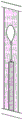
Fig. 1 shows an embodiment of a vascular catheter navigation device or system for navigating the anatomy of a human. The vascular catheter navigation device 102 is shown in a vein 104 of a patient. The vascular catheter navigation device has been inserted into the patient via insertion point 106. The insertion point is shown here in the chest of the patient, however the insertion point may alternatively be the leg, arm or neck or other location of the patient. In order to navigate a standard vascular catheter to its desired location, several undesirable obstacles need to be avoided and/or overcome. For example, a vascular catheter may be incorrectly placed in an artery rather than a vein; vascular catheters may risk descending or ascending along the wrong branch of the vascular system; vascular catheters may be secured against the walls of the blood vessel; vascular catheters may be advanced too far, too close to the heart, into or through the heart; or the vascular catheter may not be advanced far enough to reach its desired location, or may migrate to a less desired location. With several of these danger areas being labeled 116. The distal tip of the vascular catheter navigation device is shown at 108. At the proximal end of the vessel catheter navigation device are shown: an infusion or sampling lumen 110 in fluid communication with one or more openings at or near the distal end of the vascular catheter navigation device, and a sensing port 112 in communication with a controller 114. The sensing port 112 communicates with one or more sensors (not shown here) at or near the distal tip 108 of the vascular catheter navigation device 102. Although one infusion/sampling lumen and one sensing port are shown here, there may be multiple infusion/sampling and/or sensing ports. The infusion lumen 110 may also be in communication with a controller 114.
Fig. 2 shows an embodiment of the vascular catheter navigation device in which the distal tip is placed in the superior vena cava/superior vena cava-right atrial superior wall junction (SVC-CAJ) 202.
Fig. 3 shows an embodiment of a vascular catheter navigation device. The distal end of the vascular catheter navigation device is inserted into an appropriate access vein and advanced along the vein to its target location. After insertion of the vascular catheter navigation device into the blood vessel, typically through a needle or sheath, the sensing element 302 senses a parameter within the blood vessel. A medium, such as a fluid, having a measurable parameter (e.g., temperature) is injected through the device into the blood vessel. The sensor signals are transmitted back to the controller where one or more sensor signals are analyzed based on sensor data over time, including data curve slope, amplitude, value, length, degree of change, standard deviation, shape, etc. For example, the controller may determine whether the distal end of the vascular catheter navigation device is in an artery rather than a vein based on the magnitude and direction of blood flow around the vascular catheter navigation device by measuring and analyzing the measurable parameters. An alarm or other indicator may be communicated to the user if the controller determines that the distal end of the vascular catheter navigation device is in an undesirable position. For example, if the controller determines that the catheter is in an artery rather than a vein, a specific identification signal (including an audible signal, a visual signal, etc.) may be issued instructing the user to remove the vascular catheter navigation device, as well as any other devices, such as a sheath, catheter, etc., and apply pressure to the blood vessel.
Similarly, the vascular catheter navigation device may sense when the distal end is in the wrong branch of the vein based on the direction of flow and possibly the flow pattern and size. When the catheter navigation device is advanced in the correct direction and in the correct vessel (towards SVC-CAJ, in the vein), blood flows from more proximal to distal over the catheter navigation device.
Fig. 3 shows one sensor 302, one sensor port 112, and one infusion/sampling lumen 110. However, there may be more than one infusion/sampling lumen and/or more than one sensor. In addition, the port to the controller and the sampling lumen may be the same lumen and may be incorporated into a single lumen catheter. Infusion and/or sampling lumens may also be connected to the controller.
Figure 4 shows the effect of the direction of fluid flow relative to the catheter tip on the flow behaviour before, during and after injection of a bolus of fluid. At time 0, device 102 is in vessel 404. The device 102 includes a sensor 302. The sensor 302 is designed to measure a parameter of the blood and/or the injection medium. A controller (not shown) communicates with the sensor 302 via a connector 402, which in this example extends the length of the catheter back to the controller. The sensor 302 and connector 402 may be incorporated into a vascular catheter, or may be incorporated into a stylet extending through the catheter. At time x, medium 410 is introduced into the blood vessel. For example, the medium may be saline, which is at a different temperature than the body. The parameter measured by the sensor in this example would be temperature. After injection, at T ═ x +1, the blood flow will carry media with the blood flow. With the blood flow 406 flowing out of the catheter, the bolus of media 404 travels out of the catheter tip and out of the sensor. With the blood flow 408 flowing toward the catheter, the bolus of media 410 travels toward and over the catheter tip. This embodiment shows a fluid bolus, but fluid flow may also be used.
Depending on the location of one or more sensors, different temperature profiles over time may be measured. Variables of flow rate, direction, turbulence, etc., will affect the mixing of the blood with the medium and affect the distribution of the parameter (in this example, temperature) over time. In this way, the system can determine the direction of blood flow at or near the tip of the catheter.
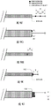
Fig. 5A-5E and 6A-6E illustrate several example embodiments of a vascular catheter navigation device. Fig. 5A illustrates one embodiment with a sensor 302 at the catheter tip. Figure 5B illustrates one embodiment where the sensor is near but not at the tip of the catheter. This configuration may prevent the sensor from measuring parameters during introduction of the medium from the catheter tip, allowing a better differentiation of the flow direction. Fig. 5C shows an embodiment with 2 sensors, one at the catheter tip and one near but not at the catheter tip. The sensor readings at different locations will vary based on fluid flow direction, characteristics, pattern, etc. A sensor near but not at the tip of the catheter may return from the tip by about 0.05cm to about 2.0 cm. Alternatively, a sensor near the tip of the catheter but not at the tip of the catheter may return from the tip by about 0.75cm to about 1.25 cm. Fig. 5D illustrates one embodiment of a sensor on a guidewire or stylet 502. The stylet 502 can be free to move within the catheter, allowing one or more sensors to be placed at a distance from the catheter tip. In addition, the guidewire/stylet may be removed after catheter placement. In this embodiment, the catheter may also include a sensor, as shown herein. Fig. 5E shows one embodiment with an opening 504 near but not at the catheter tip. The opening may be in fluid communication with a separate media introduction lumen or infusion lumen. The specific medium introduction lumen may exit at the catheter tip. The opening near but not at the tip of the catheter may be about 0.5cm to about 2.0cm back from the tip. Alternatively, the opening near but not at the tip of the catheter may be back from the tip by about 0.75cm to about 1.25 cm. The media introduction lumen may be in a catheter or may be within a stylet.
Fig. 6A shows one embodiment with an opening between two sensors, both near but not at the catheter tip. Figure 6B illustrates one embodiment having more than one sensor near but not at the tip of the catheter. Fig. 6C shows an embodiment with an opening between two sensors, one at the catheter tip. FIG. 6D illustrates one embodiment that includes openings near 2 sensors. Fig. 6E shows one embodiment with a channel 602. The channel 602 allows fluid to flow within the conduit proximate to the sensor within the conduit.
Obviously, many variations of these and other embodiments of the vascular catheter navigation device are contemplated. For example, sensors, openings, channels, etc. may be located on different sides of the catheter and/or guidewire/stylet. The sensors, openings, and channels are shown here at or near the catheter tip, however, they may be positioned anywhere along the catheter and/or guidewire/stylet.
Fig. 7A shows temperature versus time data for various locations of a porcine vasculature using one embodiment of a vascular catheter navigation device. The embodiment used to obtain this data has two temperature sensors-a distal sensor (T1) closest to the tip of the device (and therefore in this case closest to the heart), and a proximal sensor (T2). Temperature versus time curves for two sensors at 5 different locations within the vasculature, superior vena cava-to-right atrial wall junction, right atrium, right ventricle, and inferior vena cava are shown. The first two locations, the superior vena cava and the junction of the superior vena cava and the right atrial upper wall, represent proper placement of the vascular catheter navigation device. The other three positions indicate incorrect placement of the device. Note that the three temperature versus time curves on the right (representing incorrect placement) are characterized differently than the first two curves (representing correct or near-correct placement). It is further noted that the three curves to the right can also be distinguished from each other. Different sensor configurations will result in different curve characteristics for different vessel locations. For example, a single temperature sensor will provide a different set of curves than a system with 2 temperature sensors. The distance of the sensor or sensors from the infusion outlet position will also provide different curves. Different infusion rates, infusion volumes, infusion types (bolus versus flow), infusion pressures, infusion rates, etc. will also provide different curves and thus different anatomical features. Different aspects of the curve may be analyzed by the controller to determine the vessel location. These may include, but are not limited to, slope, amplitude, value, length, degree of change, standard deviation, shape, area under the curve, fourier transform, frequency, harmonics, and the like. In some embodiments, certain frequencies in the data may be filtered out, including frequencies related to heart beat, system noise, and the like.
In some embodiments, there is one temperature sensor, and thus one temperature versus time curve. In some embodiments, there are two or more temperature sensors, and thus two or more temperature versus time curves. The graph of 2 temperature sensors is shown in fig. 7A. In some embodiments, the infusion outlet port is proximate to one or more proximal temperature sensors. In some embodiments, the infusion outlet port is proximal or distal to the one or more temperature sensors. In some embodiments, the infusion outlet port is between the temperature sensors. In some embodiments, one or more than two temperature sensors may be used.
Fig. 7B and 7C show two alternative temperature versus time curves. Note that the curves may look different in different anatomical structures and based on the design of the vascular catheter navigation device. For example, the curves may be different for different sensor positions relative to the fluid outlet port. The curve may depend on the type of sensor or the fluid injection rate. The curve may depend on the initial temperature of the injection fluid. Other design factors may also result in different temperature versus time curve shapes.
Additionally, calibration of the temperature versus time curve may be performed by the controller. For example, baseline measurements may be derived after insertion into the system or at other points in time during use of the system. For example, a baseline measurement may be taken in a blood vessel prior to injection of any injection fluid or while injecting at a particular injection rate. An example of which is shown in fig. 7B. The "baseline" data is shown in the graph, where the temperature measurements were taken without any fluid injection through the system. This baseline measurement can be used in data analysis by the controller to determine the position of the vascular catheter navigation device within the anatomy.
Various characteristics of the temperature versus time curve may be analyzed to determine the position of the vascular catheter navigation device. For example, curve amplitude, noise, standard deviation, shape, slope, value, area under the curve, fourier transform, frequency, harmonics, etc. of one or more curves may be used to determine the position of a vascular catheter navigation device within the vasculature. These same parameters may be compared between multiple temperature versus time curves to determine the placement of the vascular catheter navigation device. For example, the position, relative position, size and/or relative size of the peaks (positive or negative) of the curve may be used to determine the position of the vascular catheter navigation device. Additionally, the amplitude, noise, standard deviation, shape, slope, value, area under the curve, and/or difference between fourier transforms, harmonics, frequencies of data from multiple temperature sensors may be used to determine the vessel location. Depending on droplet size and/or infusion rate, the area under the curve or the Fourier transform can be used to analyze the temperature versus time curve and hence the vessel location. In addition, the maximum or maximum number may be more relevant. .
The term "droplet" as used herein when referring to an injectate can mean a droplet, a bolus, a stream, an intermittent stream, and the like.
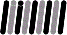
Fig. 8 is a schematic diagram showing fluid flow in different regions of the vascular system representing desired (correct) and undesired (incorrect) device placement. Arrow 802 shows the direction of blood flow. Region 804 shows fluid (e.g., saline) infusion. Note how different anatomical locations will produce different flow conditions and therefore different dissipation modes of fluid infusion. Although 1 temperature sensor 806 is shown here, two, three, four, five, six, or more temperature sensors may be used here and in any other embodiment disclosed herein.
Fig. 9A-9E illustrate various embodiments of a vascular catheter navigation device with two temperature sensors on the guidewire/stylet. Fig. 9A shows a stylet 910 having a proximal temperature sensor 902 and a distal temperature sensor 904. Injectate 906 in this embodiment exits at the distal tip of catheter 908, near or near proximal temperature sensor 902. Alternatively, the injectate can be injected through the lumen of a guidewire/stylet. Although 2 sensors are shown here, one or more than two sensors may be used.
Fig. 9B shows one embodiment where the injectate is injected through the stylet/guidewire and exits between the two temperature sensors. Fig. 9C shows one embodiment where the injectate is injected through the stylet/guidewire and exits near or distal to the distal temperature sensor. If one temperature sensor is used, the fluid injection outlet port may be proximal or distal to the sensor.
Figures 9D and 9E illustrate one embodiment having two temperature sensors on the stylet/guidewire, where the guidewire is movable relative to the end of the catheter. This embodiment can be used to change the sensing and/or injectate exit position relative to the catheter tip.
For example, in some embodiments, the stylet/guidewire may include both an injector lumen (i.e., the stylet/guidewire may be hollow) and a temperature sensor, such that the stylet/guidewire may be first and/or independently positioned in the anatomy from the vascular catheter. For example, when the jugular vein access is used for catheterization. Once the stylet/guidewire is placed, the vascular catheter may be advanced so that the distal tip of the catheter is at a known position relative to the distal tip of the stylet/guidewire. The stylet/guidewire may then be removed.
Fig. 9F-9H illustrate the distance between the fluid outlet port and the one or more temperature sensors and the distance between the catheter/stylet tip and the one or more sensors/ports. Fig. 9F shows the axial distance aa between the injectate outlet or port and the distal or single temperature sensor. The axial distance bb is the distance between the fluid outlet port and the proximal temperature sensor. The axial distance cc is the distance between the distal temperature sensor and the proximal temperature sensor. These distances may be positive or negative. Although 2 temperature sensors are shown here, the device may have one sensor or more than two sensors.
The distance aa may be about 0 mm. Alternatively, the distance aa may range from about 0mm to about 0.5mm, or from about 0mm to about 1 mm. Alternatively, the distance aa may range from about 0mm to about 2 mm. Alternatively, the distance aa may range from about 0mm to about 3 mm. Alternatively, the distance aa may be about 3mm to about 5 mm. Alternatively, the distance aa may be about 5mm to about 10 mm. Alternatively, the distance aa may range from about 0mm to about 100 mm. These distances may also be negative. For example, the distance aa may be about 1mm or may be about-1 mm. In the case of 1mm, the distal temperature sensor will be distal to the fluid outlet port. In the case of-1 mm, the fluid outlet port would be distal to the distal temperature sensor. This is true for all dimensions provided in connection with fig. 9F-9H.
The distance bb may be about 10 mm. Alternatively, the distance bb may range from about 0mm to about 10 mm. Alternatively, the distance bb may range from about 8mm to about 12 mm. Alternatively, the distance bb may range from about 5mm to about 15 mm. Alternatively, the distance bb may range from about 1mm to about 100 mm. Alternatively, the distance bb may be from about 3mm to about 5 mm. Alternatively, the distance bb may be from about 5mm to about 10 mm. Alternatively, the distance bb may range from about 0mm to about 100 mm. These ranges may also be negative distances.
The distance cc may be about 10 mm. Alternatively, the distance cc may range from about 0.0mm to about 5 mm. Alternatively, the distance cc may range from about 5mm to about 15 mm. Alternatively, the distance cc may range from about 15mm to about 20 mm. Alternatively, the distance cc may range from about 1mm to about 100 mm.
The distance dd in fig. 9G is the distance between the fluid outlet port and the distal temperature sensor or the proximal temperature sensor. This distance is shown here with respect to the proximal temperature sensor, but the distance dd may be applicable to either. Alternatively, there may be only one temperature sensor. The distance dd may be about 0.75 mm. Alternatively, the distance dd may be in the range of about 0.25mm to 1.5 mm. Alternatively, the distance dd may be in the range of about 0.1mm to 5 mm.
Fig. 9H shows the axial distance ee between the fluid outlet port and the end of the catheter and/or stylet. The distance ee may be about 0 mm. Alternatively, the distance ee may be in the range of about 0mm to about 1 mm. Alternatively, the distance ee may be in the range of about 0mm to about 3 mm. Alternatively, the distance ee may be in the range of about 0mm to about 5 mm. Alternatively, the distance ee may be in the range of about 5mm to about 10 mm. Alternatively, the distance ee may be in the range of about 0mm to about 100 mm. These distances may be positive or negative.
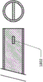
Figure 9I shows one embodiment of a vascular catheter navigation device including only one sensor in the system and including a tubing 902. Various embodiments of systems including conduits will be described in more detail elsewhere herein. Conduit 902 includes an injectate outlet port, indicated by X. The distance ff shown here is the longitudinal distance between the fluid injectate outlet port of the conduit and the sensor.
FIG. 9J illustrates an embodiment similar to that of FIG. 9I, wherein the distance gg represents the radial distance between the fluid injectate outlet port of the conduit and the sensor.
Fig. 10 illustrates one embodiment of a vascular catheter navigation device that may be used with any catheter, or in other words, where one or more temperature sensors, an injectate lumen, a controller, and a locking mechanism are included with a stylet/guidewire. Fig. 10 illustrates one embodiment having two thermocouples, a distal thermocouple 1012 and a proximal thermocouple 1010, and an injectate exit port 1002 as part of the guidewire/stylet 1001. Alternatively, the stylet/guidewire may have only one temperature sensor, or may have more than two temperature sensors. The stylet/guidewire may include features 1014 to assist in aligning the stylet/guidewire and the catheter. This embodiment may include a tip portion 1006, such as a molded urethane, nylon, silicone, or other polymer portion, for embedding one or more temperature sensors. Also shown here is the distal tip of optional guidewire/stylet coil 1008 and catheter 1018. In cross-section, the infusion lumen 1016 can also be seen.
This embodiment may include a torque or locking device 1022 that may be used to lock the stylet to the proximal end of the catheter 1018, for example, by using a luer lock 1020 at the proximal end of the catheter. The torque/locking device may be locked to the stylet/guidewire so that the stylet/guidewire does not move relative to the vascular catheter. A controller (not shown) may include and/or control the infusion mechanism via the fluid port 1026 and read data from one or more temperature sensors via the temperature port 1004. The controller may be positioned near the proximal end of the stylet, or may be positioned inches or feet from the proximal end of the stylet. Temperature sensor leads 1024 are also shown. Infusion may be steady or intermittent, or consist of a bolus.
Figures 11A-11I show various views of various embodiments of a stylet/guidewire version of a vascular catheter navigation device.
11A-11I and some other embodiments illustrate stylets having several functions, including: 1) stiffening the catheter to aid insertion; 2) providing a medium for fluid delivery; and 3) providing one or more temperature sensors with access for wiring. Figure 11A is a cross-section of a stylet such as shown in the embodiment of figure 10. Two temperature sensors are shown here, but the device may comprise one or more than two sensors.
Fig. 11B shows one embodiment of a stylet that includes three components in a triple lumen, a heat shrink, and/or a tubing housing 1102 containing two temperature sensors 1104 and a fluid lumen 1016. Alternatively, there may be one or more than two temperature sensors.
Figure 11C illustrates one embodiment in which the stylet coil is made, in whole or in part, of a temperature sensor wire. Fig. 11D is a side view of the embodiment shown in fig. 11C.
Fig. 11E shows an embodiment comprising an extrusion or tube (metal or plastic) that houses two temperature sensors and a fluid lumen. Alternatively, there may be one or more than two temperature sensors.
Fig. 11F shows an embodiment comprising an extrusion or tube (metal or plastic) that houses a plurality of thermocouples within a tube bundle and contains fluid lumens.
FIG. 11G illustrates an embodiment comprising a thin-walled extrusion or tube in which a plurality of temperature sensors are surrounded by a fluid lumen. There may be one, two or more temperature sensors.
Fig. 11H illustrates an embodiment that includes an extrusion or tube (plastic or metal) that includes a plurality of temperature sensors, a fluid lumen, and a strength member 1108, which may be a wire or rod. There may be one, two or more temperature sensors.
Fig. 11I illustrates an embodiment comprising an extrusion or tube (plastic or metal) comprising a temperature sensor tube bundle and a fluid lumen. The exterior of the temperature sensor tube bundle may be made of a material similar to the exterior extrusion that allows for optional chemical or heat formed bonding or welding 1106. There may be one, two or more temperature sensors.
In some embodiments, it may be important to fix or precisely control the distance between the catheter tip and the guide wire/stylet, or to be able to determine the distance between the catheter tip and the guide wire/stylet. It may also be important to be able to fix the position of the injection relative to the temperature sensor or to know the distance between the position of the injection outlet port and the temperature sensor. The distance between the outlet port and the temperature sensor will have an effect on the temperature profile during fluid infusion. These distances may be fixed in the patient and the scene, or may be different for different patient types and different scenes. For example, the distance may vary depending on the vasculature accessed. The distance may be different for patients of different weight, build, body mass index, health condition, age, sex, heart condition or other patient characteristics. The distance may be different for different catheter sizes, catheters with different numbers and shapes of lumens, etc.
In some embodiments, a torque device is used to fix or lock the stylet/guidewire relative to the catheter tip near the proximal end of the catheter, as shown in fig. 10.
In some embodiments, the user visually determines the relative alignment of the catheter and the stylet/guidewire and then measures the relative distance from the two values.
Fig. 12-17 illustrate various embodiments of vascular catheter navigation devices that include various registration techniques to fix or know the distance between one or more temperature sensors on the stylet and the catheter tip or fluid injection point.
Figure 12 illustrates one embodiment having an indicator on the stylet/guidewire at a fixed and known distance from the temperature sensor. In this embodiment, the user aligns the tip of the catheter 1202 with an indicator or mark 1204 on the stylet 1206 prior to insertion into the patient. Prior to insertion of the catheter into the patient, the relative distance from the catheter tip to the stylet tip 1208 can be locked, preferably proximally, using a torque device, a locking rotating hemostasis valve, tuohy-borst valve, or other locking mechanism. The indicator on the guidewire/stylet may be a visible mark such as a red stripe or dot, or a tactile mark such as a bump or groove, or other type of indicator.
Fig. 13 illustrates one embodiment having a raised area or bump 1302 on the stylet that has a fixed and known distance from the distal temperature sensor. This allows the user to visually or tactilely align the tip of the catheter with the bump on the stylet. This alignment may be performed in vitro or in vivo. In some embodiments, the bump is small enough or soft enough that the stylet can be removed from the catheter after placement in the anatomy.
Figure 14 shows an embodiment similar to the embodiment shown in figure 13 in which the temperature sensor 1104 is used as a bump on the stylet.
Figure 15 illustrates an embodiment in which a clamp, stop or aligner 1502 is used to align the tip of the catheter at a fixed and known distance from the tip of the stylet. A torque device, a locking rotary hemostasis valve, a tuohy-borst valve, or other locking mechanism is then used at the proximal end, and/or a fixed tube (disclosed in detail elsewhere herein) is used at the distal end, or both, to lock the relative position of the catheter relative to the stylet. The clamp or stop 1502 itself may be adjustable so that it can align the fluid outlet port (here the distal end of the catheter) with the temperature sensor over a variety of different lengths.
Fig. 16 shows an embodiment similar to that shown in fig. 13, in which an inflatable balloon 1602 is used as a bump to align the catheter and stylet. The balloon may be annular or on one or more sides of the stylet. The balloon may be inflated for use during alignment and remain inflated to lock the stylet in place relative to the catheter during placement, or deflated during placement (where a torque device or valve has been used to lock the catheter and stylet to one another). In this embodiment, the stylet or catheter will include an inflation lumen to inflate and deflate the balloon. After placement of the catheter, the balloon may be deflated to remove the stylet.
Fig. 17 shows one embodiment of a vascular catheter navigation device comprising a sensor 1702 that can sense when it is inside the catheter tip during use. For example, the sensor may be a magnetic, ultrasonic sensor, optical sensor, temperature sensor, or the like. In some embodiments, the proximal temperature sensor 1704 serves as a sensor for determining when the proximal temperature sensor is inside the catheter tip. The shape of the temperature versus time curve for a post-injection of an injectate will show a specific distribution when the temperature sensor is just inside the catheter tip and can be used to identify this alignment. This embodiment may include one, two or more temperature sensors.
In some embodiments, it may be important to control the flow pattern of the injectate outlet to achieve consistent results. It may also be important to compare the flow of injectate with the flow of blood flow within the vasculature/heart. The flow of injectate can be purposefully made more laminar or more turbulent to achieve these goals. Some embodiments may include a feature that directs flow and is part of a catheter or stylet. These features may be surface features that alter the surface finish of the catheter or stylet, such as a depression or orange peel finish. These features may be part of the outer diameter of the stylet/temperature sensor or the inner diameter of the fluid lumen or both.
Fig. 18A and 18B show 2 possible embodiments of flow directors (for generating laminar or turbulent flow) in the injectate lumen 1016 of a vascular catheter device. The flow director 1802 may be located at the end of the injectate lumen (as shown in fig. 18A), or may be set back from the tip of the lumen exit (as shown in fig. 18B).
Fig. 19A-19C illustrate other embodiments of vascular catheter navigation devices in which the shape of the injectate lumen controls the type of flow of fluid exiting the lumen. Some parameters that may be varied include the syringe lumen opening area, shape, topography, etc. Also shown are temperature sensors and/or stiffeners 1902.
Some embodiments may vibrate the stylet and/or catheter to create turbulent flow of injectate from the injectate lumen.
FIG. 20 illustrates one embodiment of a stylet without a syringe lumen. Fluid may be introduced through another catheter lumen (possibly on a separate catheter) upstream of the catheter tip, closer to the insertion site or elsewhere. For example, fluid may be injected via a "double-guide" catheter 2002, shown here alongside a vascular catheter. The fluid may also be heated or cooled via a heating/cooling element on the catheter or a "dual guide" catheter. Infusion of a "dual-guide" guidewire/stylet is also contemplated.
Figure 21 shows a feature 2102 for enhancing controlled turbulence in a lumen of an injectate.
Fig. 22 shows a feature 2202 that produces a controlled laminar (or less turbulent) flow in a lumen of an injectate.
Note that several embodiments disclosed herein show 2 sensors. In any of these embodiments, one, two, or more sensors may be used.
In some embodiments, the stylet has an Outer Diameter (OD) of about 1mm or less. In some embodiments, the OD of the stylet is about 0.5mm or less. In some embodiments, the OD of the stylet is about 1.5mm or less. In some embodiments, the OD range of the stylet may be about 0.2mm to about 5 mm.
In some embodiments, where the catheter is a dual or triple lumen, the function of the stylet may be divided into different parts (fluid, reinforcement, temperature sensing), etc., and multiple stylets may be used in multiple lumens of the catheter.
Many types of temperature sensors may be used in any of the embodiments disclosed herein, including thermocouples, fiber optic temperature sensors, resistive temperature sensors, bimetallic temperature sensors, thermometers, state change temperature sensors, silicon diodes, thermistors, optical temperature measurement devices (infrared or otherwise), mercury thermometers, pressure gauges, and the like.
In addition to infusing fluid, other methods may be used to generate thermal changes at or near the tip of the catheter/stylet, as disclosed elsewhere herein. A fluid at a temperature above body temperature may be introduced, a resistive heating element or a piezoelectric cooling element, etc. may be included in the catheter, on the guidewire/stylet, or at the syringe, outside the body. Alternatively, the injected fluid may be at a temperature different from body temperature but not tightly controlled, and this temperature difference (between body temperature and injectate temperature) is measured and tracked by the controller.
In embodiments having a resistive heating element, the resistive heating element can be on the catheter or on the stylet. In embodiments where the resistive heating element is located on the catheter, the resistive heating element may be on the outside of the catheter or on the inside of one or more lumens of the catheter. Alternatively, the resistive heating element may be on the guidewire/stylet. In embodiments where the resistive heating element is located on the guidewire/stylet, the resistive heating element may be within, partially within, or outside of the catheter lumen where it is exposed to blood. When heating/cooling blood, it may not be necessary to inject injectate.
As shown in fig. 23A-23E and 24A-24E, the graphical user interface may be displayed in the form of a small screen/display 2314, a large screen, projection, virtual reality or augmented reality glasses, and the like. The main category of user interaction may have any combination of the following user alerts: 1) an icon; 2) the color of the icon or warning light; 3) an audible tone accompanying the alarm; 4) a visual map of the body that matches the location of the catheter tip and the type of alarm; 5) written phrases or words on the display indicating alarm status, vibration, etc. The categories may be as follows: 1) by "continue advancing," it is meant that the catheter tip is advancing through the peripheral vein or rounding off from the bend and approaching the superior vena cava. This mode will be accompanied by visual and auditory feedback indicating a frontal status, such as green lights and icons and frontal tones. 2) "correctly placed," check mark icon shows that the tip has reached the proper location on the PICC line-the junction of the superior vena cava and the upper right atrial wall, or possibly another type of catheterization location. The front tones and lights may accompany the condition. 3) If the conduit encounters relative flow, a warning "redirection" may occur. This is when the warning catheter is advanced down the odd venous branch into the IVC, or has been placed in an artery. Since this is not a positive state, this is accompanied by a red, yellow or orange light or icon and a tone indicating the presence of an unfavorable condition. Possibly with less pleasant frequencies, pitches and tones. 4) If the catheter is In the Heart, either In the atrium or In the ventricle, the user may be alerted with a Heart icon and/or an "In Heart" (In Heart) alert. Negative facial colors and tones may accompany the state. 5) If the catheter tip is pressed up against the vein wall or there is some obstruction, an "adjustment" warning may be displayed. Negative facial colors and tones may accompany the state. Also shown in fig. 23A-23E and 24A-24E are a catheter 2302, a stylet 2304, a temperature adapter 2306, a fluid adapter 2308, an activation button 2310 and an insertion/tracking button 2312.
A Graphical User Interface (GUI) may display in real time the position of the catheter tip relative to the 3D space through which it is navigated. The graphical user interfaces shown in fig. 23A-23E and 24A-24E are two-dimensional, however some embodiments include a 3D display that can also convey information in three dimensions.
Note that although some embodiments disclosed herein incorporate one or more sensors into the vascular catheter, the vascular catheter navigation device may be a stand-alone device that fits inside the vascular catheter and may be removed once placement of the vascular catheter is complete. The vascular catheter navigation device may be used, for example, as a stylet or guidewire for a standard vascular catheter.
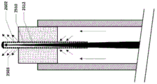
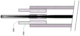
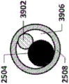
Fig. 25A-25C show an embodiment of a vascular catheter navigation device comprising tubing for controlling the fluid flow exiting from the fluid exit point of the device. In this embodiment, the tract 2502 is attached to a guidewire/stylet 2504, thereby forming a stylus/tract combination device. The tubing 2502 is designed to fit within the inner diameter of the infusion lumen 2506 of the vascular catheter 2508. In this figure, vascular catheter 2508 includes only one lumen, i.e., an infusion lumen, however, in addition to an infusion lumen, there may be multiple lumens in the vascular catheter.
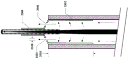
In some embodiments, the guidewire/stylet 2504 includes a core 2510, a coil 2512, an end cap 2514, and a temperature sensor 2516. The core 2510 may include a wire reinforcement, which may be tapered, and leads for a temperature sensor. The temperature sensor may be incorporated into the end cap, or it may be separate. One or more temperature sensors may be present. The temperature sensor may be a thermocouple. Thermocouples with larger cross-sectional dimensions may inhibit temperature measurement, while thermocouples with smaller cross-sectional dimensions may allow for faster response times. The diameter or cross-sectional dimension 2526 of the thermocouple may be about 0.2mm to 0.3 mm. Alternatively, the diameter or cross-sectional dimension 2526 of the thermocouple may be about.02 mm to about.5 mm.
In some embodiments, the conduit 2502 has a length 2520 and includes one or more fluid flow passages 2518 having a diameter or cross-sectional dimension 2522. The cross-sectional shape of the flow passage may be circular, elliptical or any shape. The diameter or cross-sectional dimension of the flow passage may be about 0.4mm to 0.6 mm. Alternatively, the diameter or cross-sectional dimension of the flow passage may be about 0.1mm to 1.0 mm. Alternatively, the diameter or cross-sectional dimension of the flow passage may be about 0.01mm to 2.0 mm. The conduit length 2520 may be about 4mm to 8 mm. Alternatively, the conduit length 2520 may be about 0.5mm to 20 mm.
The cross-sectional area and shape of the flow passage will determine the flow rate exiting the conduit. The number of flow paths will also affect the flow parameters of the fluid exiting the pipe. Preferably, the fluid infusion rate may be about 2ml/min to 3 ml/min. Alternatively, the fluid infusion rate may be about 3ml/min to 5 ml/min. Alternatively, the fluid infusion rate may be about 5ml/min to 10 ml/min. Alternatively, the fluid infusion rate may be about 1ml/min to 5 ml/min. The outlet flow rate of the conduit is preferably about 60cm/s to 100 cm/s. Alternatively, the conduit outlet flow rate is from about 1cm/s to 300 cm/s.
The conduit 2502 may be used for several purposes:
1) substantially seals the distal end of the infusion lumen of the vascular catheter while allowing fluid flow through/past the tubing such that when fluid is injected through the infusion lumen of the catheter, a majority of the fluid exits the vascular catheter via one or more flow paths 2518. It is important to note that the tubing does not completely occlude the infusion lumen of the catheter, the tubing allowing fluid to pass therethrough and, in some cases, through the channels surrounding it.
2) Such that the distance 2524 between the fluid exit point 2503 and the sensor on the guidewire/stylet is known and fixed for more controlled temperature measurements in the vasculature. The fluid exit point may be an exit point at the distal end of one or more flow paths of the tubing, or may be the distal end of the catheter, depending on whether the tubing partially extends beyond the distal end of the catheter. The distance 2524 may be about 0.0mm to 1.0 mm. Alternatively, the distance 2524 may be about 0.5mm to 1.0 mm. Alternatively, the distance 2524 may be about 0.0mm to 2.0 mm. Alternatively, the distance 2524 may be about 0.0mm to 5.0 mm. Alternatively, the distance 2524 may be about 0.0mm to 10.0 mm. As used herein, "about 0.0" or "substantially zero" may mean + -1mm, or "substantially zero" may mean + -2 mm, or "substantially zero" may mean + -3 mm. This may be true for any of the embodiments disclosed herein.
3) One or more fluid outlet points of the conduit are centrally aligned or otherwise aligned with the temperature sensor.
4) One or more fluid outlet points are aligned with the center of the catheter tip or otherwise aligned.
5) Controlling the flow characteristics of the fluid exiting the one or more exit points. For example, the size, shape, and number of outlet ports will control the flow characteristics of the fluid exiting one or more ports. Parameters such as turbulence, flow rate, volumetric flow rate, flow, etc. may be controlled. In addition to the rate of fluid infusion, the cross-section of flow path 2518 will determine the rate of infusion out of flow path 2518. The rate of infusion rate may be adapted to the velocity of blood flow.
The outer surface of the tubing is substantially sealed to the inner surface of the infusion lumen of the vascular catheter without having to perfectly align the guidewire/stylet with the vascular catheter. Because vascular catheters are larger and more flexible than stylets, the relative alignment of the distal tips of each may vary during the procedure. In the case where the length of the tubing is longer than this variation, the tubing may still seal the infusion lumen of the vascular catheter even if the stylet/tubing combination and the distal tip of the vascular catheter move relative to each other. Alternatively or additionally, the tubing may secure the guidewire/stylet to the vascular catheter such that one does not move relative to the other, at least longitudinally.
The cross-sectional dimension/diameter of the conduit may be about 0.5mm to 1.5 mm. Alternatively, the cross-sectional dimension/diameter of the conduit may be about 0.1mm to 3 mm. In some embodiments, the gap between the exterior of the tubing and the interior of the infusion lumen of the vascular catheter will be small enough to allow a substantial seal between the exterior of the tubing and the interior of the infusion lumen of the vascular catheter. This forces substantially all of the infused fluid out of the flow path 2518, thereby controlling the distance between the fluid outlet and the temperature sensor. The gap between the exterior of the tubing and the interior of the infusion lumen of the vascular catheter may also be large enough to allow the stylet/tubing combination to move within the infusion lumen of the vascular catheter for positioning and/or removal. The outer surface of the tube may be coated or fabricated from a lubricious material such as PTFE, hydrophobic materials, hydrophilic materials, and the like. The gap between the exterior of the tubing and the interior of the infusion lumen of the vascular catheter may be about 0.070mm to 0.080 mm. Alternatively, the gap between the exterior of the tubing and the interior of the infusion lumen of the vascular catheter may be about 0.05mm to 0.1 mm. Alternatively, the gap between the exterior of the tubing and the interior of the infusion lumen of the vascular catheter may be about 0.001mm to 1.00 mm.
Note that the gap between the exterior of the tubing and the interior of the infusion lumen of the vascular catheter may be different for embodiments of the tubing that are inflated/deflated or have features that are inflated/deflated, such as those shown in fig. 27, 28, 29A-29C, 30, 36A-36C. For example, the gap in the deflated state may be greater than the gap of the unexpanded/deflated conduit, and the gap in the inflated state may be less than the gap of the unexpanded/deflated conduit. For example, the gap in the expanded state may be substantially zero.
Fig. 25A shows the distal end of the tube 2502 substantially aligned with the distal end of the catheter 2508. FIG. 25B shows an embodiment in which the distal end of the tubing is designed to be located inside the distal end of the infusion lumen of the catheter for infusion, FIG. 25C shows an embodiment in which the distal end of the tubing is designed to be located outside the distal end of the infusion lumen of the catheter for infusion.
In use, the stylet/tubing combination device is inserted (or advanced inserted) into the infusion lumen of the vascular catheter. The catheter is then inserted and advanced through the vasculature. As the device is advanced, fluid is infused through the infusion lumen. Because the tubing substantially seals the infusion lumen of the catheter, fluid exits the system through the flow path of the tubing and flows through the vasculature, and the temperature sensor senses the temperature of the blood/fluid in the vasculature. The distance between the one or more outlet points of the fluid and the temperature sensor is fixed/known and the temperature versus time curve is related to the flow characteristics in the vessel. Different features of these curves are used to identify the position of the tip of the vascular catheter navigation device. After the system has been navigated to its desired location, the stylet/tubing combination is removed and the infusion lumen of the vascular catheter is then used as a standard infusion lumen. The stylet/tubing combination can be later reinserted into the infusion lumen of the vascular catheter to confirm the location of the tip of the vascular catheter.
Figure 26 illustrates one embodiment of a vascular catheter navigation device in which the flow path is within the guidewire/stylet component itself. In this embodiment, tubing is used to substantially seal the end of the infusion lumen of the catheter, but the flow path flows between the stylet core 2510 and the stylet coil 2512 and exits via the opening 2602 between the coils.
Fig. 27 shows a variation of the tubing including a proximal flange 2702. The flange may act as a seal to substantially seal the tubing to the inner diameter of the infusion lumen of the catheter when fluid injected through the infusion lumen of the catheter is above a certain pressure. When fluid is no longer infused through the infusion lumen, or when the infusion pressure drops below a certain pressure, the flange 2702 may collapse slightly, reducing the diameter or cross-sectional area of the tubing at the flange, which allows the stylet/tubing combination to be removed from the vascular catheter after the position of the vascular catheter has been established. Alternatively, the flange may be invaginated and flipped in direction during the retraction motion, thereby facilitating removal of the stylet/conduit combination. Fig. 28 shows a variation of the embodiment shown in fig. 27, wherein the tube has a proximal flange and a distal flange. Note that in these and other embodiments disclosed herein, during use, i.e., during navigation of the catheter, the distal end of the tube may be flush with the distal tip of the catheter, distal to the distal end of the catheter, or proximal to the distal end of the catheter.
Fig. 29A-29C illustrate an embodiment of a vascular catheter navigation device in which the tubing comprises a thin-walled inflatable structure. Fig. 29A shows a tube having a thin-walled inflatable proximal portion 2902 and a distal portion 2904, wherein the distal portion is bonded or otherwise attached to a stylet. The proximal portion 2902 of the conduit includes one or more openings 2906. As fluid is infused through the infusion lumen of the catheter, the proximal tubing portion 2902 expands, substantially sealing the inflatable portion against the inner wall of the infusion lumen. Infusion fluid also exits the catheter via opening 2906. The opening must be small enough to allow the pressure within portion 2902 to increase such that the portion "inflates" inside the infusion lumen. The opening must be large enough to allow enough fluid to escape into the bloodstream for meaningful temperature measurements to be made. The diameter or cross-sectional dimension of the one or more openings may be about 0.4mm to.06 mm. Alternatively, the diameter or cross-sectional dimension of the one or more openings may be about 0.05mm to 1.0 mm. The proximal portion 2902 of the conduit may be about 0.3mm to 0.5mm in length 2910. Alternatively, the length 2910 of the proximal portion 2902 of the conduit may be about 0.3mm to 20 mm.
To remove the stylet/tubing component from the vascular catheter, the fluid infusion is reduced or reversed to "pinch" the proximal portion 2902 of the tubing so that the stylet/tubing can be removed. This is shown in fig. 29B. In some embodiments, constriction may not be necessary, and the stylet/tubing may be removed from the vascular catheter while fluid infusion is taking place.
Fig. 29C shows a variation of an inflatable tube with a collar 2912 that may help direct fluid flow as it exits the tube.
One of the advantages of an "inflatable" tube is that the shape of the tube can conform to any shape of infusion lumen (whether circular, semi-circular, triangular, elliptical, etc.). The difference in cross-sectional area between the deployed and undeployed tubing can be quite large, which is useful in smaller infusion lumen devices.
FIG. 30 shows an embodiment of a tube with a thin-walled "skirt" 3002. The "skirt" expands and contracts similar to the "inflatable" portion of the embodiment shown in fig. 29A and 29B.
Fig. 31 illustrates an embodiment of a conduit including one or more features 3102 that help direct the flow of fluid exiting the conduit. The features may direct flow in a parallel manner as shown in fig. 31, in an inward manner as shown in fig. 32, or in an outward manner as shown in fig. 33, or in any other manner.
Figure 34 shows an embodiment with a deflector 3402 that helps to keep the system off the vessel wall. The deflector may be spherical, or substantially spherical, or any other shape. The deflector may have a diameter or cross-sectional dimension of about 0.3mm to 0.4 mm. Alternatively, the deflector may be about 0.01mm to 1.0mm in diameter or cross-sectional dimension.
Fig. 35 illustrates one embodiment of a tube that is conical to aid in sealing within the infusion lumen of a catheter during an injection.
Figures 36A-36C illustrate one embodiment of a vascular catheter navigation device including a compressible tubing 3606. The compressible tube may be made of silicone, polymer, or other suitable material. Fig. 36A shows the tubing in its compressed state. In this state, the tubing substantially seals the infusion lumen of the catheter. Fig. 36B shows the compressible tubing in its decompressed state, reduced in diameter/cross-sectional dimension so that it can be repositioned and/or removed. Compression/decompression of the tubing may be performed by a rod or hypotube (hypotube) or tube 3602 that is connected to the proximal end of the compressible tubing and can be manipulated (pushed, pulled, twisted, etc.) from the proximal end of the catheter to compress and decompress the tubing. Fig. 36C shows a variation of the system that allows a user to compress/decompress a tube by rotating a rod/hypotube/tube 3604 that has threads that engage the tube. (the idea of the new embodiment: a very small balloon can be used to activate and remove the seal.
Figures 37A-37F illustrate 2 different cross-sectional views of various embodiments of a vascular catheter navigation device. Fig. 37A shows one embodiment of the guidewire/stylet 2504 being substantially centered in the tubing 2502 within the infusion lumen of the vascular catheter 2508. One or more of the flow passages 2518 can have a different cross-sectional shape, such as spherical, triangular, the shape shown here, and others. There may be one, two or more flow paths. The guidewire/stylet may include a sensor lead 3702.
Fig. 37B shows an embodiment of a vascular catheter navigation device in which the guidewire/stylet is off-center. The cross-sectional views show various possible configurations of the guidewire/stylet and fluid passageway. The one or more flow paths may be circular, crescent-shaped, etc. One, two, or more flow paths may be present in any of the embodiments disclosed herein. Note that the conduit may be a simple tube, as shown at 3704.
Fig. 37C shows one embodiment of a vascular catheter navigation device in which the guidewire/stylet is off-center and the tip of the guidewire/stylet is angled to align with the flow path in the tubing so that the temperature sensor 2516 is generally aligned with the flow path. The tip of the guidewire/stylet may also be aligned in other ways, for example, falling between the flow paths or simply near the center of the catheter. The cross-sectional views show various possible configurations of the guidewire/stylet and fluid passageway. The one or more flow paths may be circular, crescent-shaped, etc. The conduit may be a simple tube.
Figure 37D illustrates one embodiment of a vascular catheter navigation device in which the tubing is a simple tube and the guidewire/stylet floats within the inner diameter of the tubing (where the inner diameter of the tubing is the same as the flow path of the tubing) or is attached to the inner wall of the tubing. The guidewire/stylet may be angled so that the temperature sensor is more aligned with the center of the conduit flow passage, either straight or bent or curved in some other manner.
Fig. 37E and 37D illustrate one embodiment of a catheter navigation device including a cage or stent 3706 that centers the sensor 2516 over a central flow path within a conduit. The cage/stent may be made of wire, polymer, may be made of porous material, etc. The cage/bracket may be embedded in or attached to the pipe.
Fig. 37F shows an embodiment of the vascular catheter navigation device in which the tubing 2502 does not have an outer surface. In this embodiment, the flow path is in direct contact with the inner diameter of the conduit 2508.
Fig. 38A-38E illustrate some possible architectures of various embodiments of vascular catheter navigation devices. Fig. 38A shows a vascular catheter 2508, a guidewire/stylet 2504 and tubing 2502 and an iv bag 3802, and an optional infusion pump 3804, wherein the infusion bag is connected to a fluid infusion port 2806 of the vascular catheter. The guidewire/stylet is inserted/removed from the catheter via stylet port 3808. In some embodiments, the stylet port of the catheter may be the same port as the infusion port. The stylet/sensing connector 3810 is connected to a controller 3812, which may include a display 3814 and one or more controls 3816. In this embodiment, fluid infusion through the vascular catheter and through one or more flow paths of tubing is controlled by an IV bag/infusion pump. The iv bag may be set to a consistent drip, flow and/or may be controlled by an infusion pump. In this embodiment, the iv bag and/or infusion pump are connected to the vascular catheter without passing through the controller. Fig. 38B shows a similar embodiment, except that the flow of iv fluid from the iv bag is controlled by a controller. The iv bag 3802 is connected to a controller via an iv fluid line 3818. The controller controls the infusion of fluid from the iv bag and delivers the fluid to the catheter via the catheter fluid line 3820. The controller may be disposable or reusable. The kit may also be equipped with a disposable line attached to an iv bag or a hospital infusion pump.
Fig. 38C illustrates one embodiment of a vascular catheter navigation device including a fluid pump 3822, such as a syringe pump. The fluid pump may be a standard off-the-shelf fluid pump. Note that in this embodiment, the fluid pump is not connected to the controller.
Fig. 38D illustrates an embodiment in which the fluid pump 3824 is connected to a controller such that the controller can control the delivery of fluid to the catheter via the fluid pump. The controller may have a module that allows a user to attach an off-the-shelf fluid pump, or the controller may require a specific fluid pump. The fluid pump and/or syringe barrel within the fluid pump may be disposable.
Fig. 38E illustrates one embodiment of a fluid pump incorporated into the controller 3812. The fluid pump and/or syringe barrel within the fluid pump may be disposable.
Fig. 39A is a longitudinal cross-sectional view of a vascular catheter navigation device including a tubing 2502, a guidewire/stylet 2504, a sensor 2516, and a vascular catheter 2508.
Figure 39B illustrates one embodiment of a vascular catheter navigation device having multiple tracts along the length of the guidewire/stylet. There may be 0, 1, 2, 3, 4, 5, 6 or more conduits.
Figure 39C illustrates one embodiment of a vascular catheter navigation device having a tube 2502 and a fixed tube 3902. In some embodiments, the fixed conduits are inflatable, such as balloons, but they may also be compressible, such as silicone or another soft/pliable material, such as any suitable polymer. Fixed conduits may alternatively be made of a harder material (e.g., epoxy, or metal, or polymer, etc.). Preferably, the fixed tubing secures the guidewire/stylet to the lumen of the catheter so that the stylet does not move significantly longitudinally relative to the catheter. As a result, the distance between the fluid outlet point and the sensor is substantially fixed. The movement of the sensor relative to the fluid exit point may be limited to ± 1 mm. Alternatively, the movement of the sensor relative to the fluid exit point may be limited to ± 2 mm. Alternatively, the movement of the sensor relative to the fluid exit point may be limited to ± 3 mm. Preferably, the stationary tubing also allows fluid to flow therethrough when the stationary tubing is stationary and through the catheter lumen during infusion. There may be 0, 1, 2, 3, 4, 5, 6 or more fixed pipes. In embodiments where the guidewire/stylet includes a balloon, it also includes an inflation lumen. The balloon may be relatively non-compliant or relatively compliant. An advantage of a non-compliant balloon is that the non-compliant balloon will maintain its shape or roundness when inflated above a critical pressure. This will prevent the balloon from conforming to the infusion lumen and thus being filled. In contrast, the non-compliant balloon will remain relatively circular when inflated, and a fluid flow lumen will be available between the inner wall of the catheter infusion lumen, the reinforcement/electrodes, and the stationary conduits, as shown in fig. 39G.
Fig. 39D illustrates one embodiment of a vascular catheter navigation device with a fixed conduit 3902. In this embodiment, a fixed pipe may be used as the pipe. The fixed conduit may be at the tip of the catheter, or may be further proximally back from the tip of the catheter to length 3904. Length 3904 may be about 0mm to 0.5 mm. Alternatively, length 3904 may be about 0mm to 1.0 mm. Alternatively, length 3904 may be about 0.5mm to 1.0 mm. Alternatively, length 3904 may be about 0mm to 5 mm. Alternatively, length 3904 may be about 0mm to 10 mm. Alternatively, length 3904 may be about 0mm to 20 mm. Alternatively, length 3904 may be about 0mm to 30 mm. Alternatively, length 3904 may be about 0mm to 40 mm. Alternatively, length 3904 may be about 0mm to 50 mm. Alternatively, length 3904 may be about 0mm to 60 mm. Alternatively, length 3904 may be about 0mm to 70 mm. Alternatively, length 3904 may be about 0mm to 80 mm. Alternatively, length 3904 may be about 0mm to 90 mm. Alternatively, length 3904 may be about 0mm to 100 mm.
The length of fixed conduit 3902 can be about 1 mm. Alternatively, the length of the fixed conduit 3902 can be about 1mm to 2 mm. Alternatively, the length of the fixed conduit 3902 can be about 1mm to 3 mm. Alternatively, the length of the fixed conduit 3902 can be about 1mm to 4 mm. Alternatively, the length of fixed conduit 3902 can be about 0.5mm to 5 mm.
39E-39G illustrate radial cross-sectional views showing some embodiments of stationary conduit 3902. In fig. 39E, there are 3 balloons or soft protrusions around the guidewire/stylet 2504. Fig. 39F shows 2 balloons/protrusions and fig. 39G shows only one balloon/protrusion. Note that one or more flow pathways 3906 of these fixed conduits are one or more spaces between the fixed conduits and the lumen of the catheter 2508, and, like the conduits shown in fig. 37F, do not have an outer surface. In several of these embodiments, the flow path is in direct contact with the inner diameter of the conduit 2508.
In one embodiment, the fixed conduit 3902 is a small silicone protrusion or inflatable balloon near the distal end of the stylet/guidewire and thus serves as a conduit. Prior to insertion, the guidewire/stylet is placed in the desired position so that the temperature sensor is properly positioned relative to the distal tip of the catheter. At this point, the fixed conduit may be "activated," for example, by inflating a balloon. The fixed tubing maintains the relative positions of the guidewire/stylet and catheter during placement. During placement, fluid is injected through the catheter, through the stationary tubing and out the distal tip of the catheter. For removal, the fixed tubing is either collapsed or flexible enough to allow the guidewire/stylet to be removed from the catheter. When activated, the sealed conduit 3902 can have a cross-sectional dimension that is greater than a cross-sectional dimension of the guidewire/stylet 2504. The cross-sectional dimension of the tubing may be about 0.05mm greater than the cross-sectional dimension of the guidewire/stylet. Alternatively, the cross-sectional dimension of the tubing may be about 0.05mm to 0.1mm larger than the cross-sectional dimension of the guidewire/stylet. Alternatively, the cross-sectional dimension of the tubing may be about 0.05mm to 0.5mm greater than the cross-sectional dimension of the guidewire/stylet. Alternatively, the cross-sectional dimension of the tubing may be about 0.5mm to 1.0mm greater than the cross-sectional dimension of the guidewire/stylet. Alternatively, the cross-sectional dimension of the tubing may be about 1.0mm to 2.0mm greater than the cross-sectional dimension of the guidewire/stylet.
Fig. 39H illustrates one embodiment of a vascular catheter navigation device including a plurality of fixed conduits 3902. Multiple fixed conduits may allow for better longitudinal fixation between the guidewire/stylet and the catheter near the distal end of each. Note that in this example, length 3905 is substantially zero, which is the case when sensor 2516 is substantially at the distal tip of the catheter. "substantially zero" may mean ± 1mm, or "substantially zero" may mean ± 2mm, or "substantially zero" may mean ± 3 mm. This may be true for any of the embodiments disclosed herein.
FIG. 39I illustrates an embodiment of the vascular catheter navigation device in which the stationary tubing is a coiled tubing. The coil stabilizes and centers the guidewire/stylet within the infusion lumen of the catheter while allowing fluid flow through the tubing. The helical tube is preferably open at the end to allow fluid to flow therethrough.
Fig. 39J illustrates one embodiment of a vascular catheter navigation device, where the fixed conduit 3902 is one or more wires or filaments that fix the stylet relative to the catheter lumen via outward mechanical force. The filament may extend along the length of the guide wire/stylet and may be expanded/retracted using a mechanism at the proximal end of the guide wire/stylet. The filaments may be a single strand of metal, or may be a cage or a helix, etc.
Markers or any other mechanism may be used to align the tubing with the distal end of the catheter for catheter navigation. For example, a movable marker may be present on the proximal end of the guidewire/stylet so that the distal tip of the vascular catheter (possibly after being cut to length) may be aligned with a tract outside the body, the movable marker moved so that it may be aligned with the proximal end of the vascular catheter, and the catheter may then be inserted into the body. Other mechanisms include valves, such as tuo-borst valves, or clamps, torque devices, and the like. The length of the tubing may be long enough so that precise alignment of the distal tip of the catheter with the distal tip of the tubing is not necessary. For example, the vascular catheter may move about 0mm to 2mm relative to the guidewire/stylet during the placement procedure. Alternatively, the vascular catheter may be moved about 0mm to 4mm relative to the guidewire/stylet during the placement procedure. The tubing may be longer than this, for example about 2mm to 12mm, to accommodate these variations in alignment and to ensure that the tubing spans the distal tip of the catheter.
Some embodiments of the vascular catheter navigation device may restrict the tubing from exiting the distal end of the vascular catheter. Some embodiments may allow the tubing to exit the distal end of the vascular catheter. The proximal end of the tubing may be tapered proximally to a smaller cross-sectional area so that the tubing may be pulled back into the catheter without becoming jammed.
Figures 40A-40C illustrate some different configurations of vascular catheter lumens and variations of embodiments of vascular catheter navigation devices working therewith. The vascular catheter may have one, two, three, four, five or more lumens. Fig. 40A illustrates some exemplary configurations of 2 lumen vascular catheters. These configurations include infusion lumen 2506 and accessory lumen 4002. The auxiliary lumen may be another infusion lumen, a sampling lumen, a pressure lumen, a guidewire/stylet lumen, a tool lumen, or a lumen for any other purpose. Shown here are a guidewire/stylet 2504, tubing 2502, one or more flow paths 2518, and a vascular catheter 2508. Some of the various components of the vascular catheter navigation device, including the stylet, tubing, and one or more flow passages, may have different cross-sectional shapes to accommodate different shaped vascular catheter lumens. Some examples are shown here, but others are contemplated. The shape of the tube may be preformed, for example in the form of a polymeric tube, for example, via an inflatable or conformable tube, or may take the shape of a lumen, for example, as shown in fig. 27, 28, 29A-29C, 30, and 36A-36C.
Fig. 40B shows some examples of configurations of 3-lumen vascular catheters. Fig. 40C shows an example of the configuration of a 4-lumen vascular catheter.
Note that although the embodiments disclosed herein show the vascular catheter navigation device in the infusion lumen of the vascular catheter, it is also possible that the vascular catheter navigation device may be used with any lumen of the vascular catheter, such as a sampling lumen. It is also possible to use more than one vascular catheter navigation device in more than one lumen simultaneously.
Figures 41A-41F illustrate various embodiments of a guidewire/stylet component of a vascular catheter navigation device. Fig. 41A shows a guidewire/stylet 2504 that includes a core 2510, a coil 2512, an end cap 2514, and a temperature sensor 2516. Also shown here are temperature sensor leads 4102, temperature sensor lead insulation layers 4104, stiffeners 4108, and core housing 4106. Temperature sensor leads connect the temperature sensor on the distal end of the device to a controller on the proximal end of the device. There may be one, two or more leads. For example, a thermocouple will typically have 2 leads. However, some thermocouples may have 3 leads if one of the leads is ground. The leads are preferably made of metal. The leads may be insulated with an insulating layer 4104 surrounding each lead. In some embodiments, only one of the leads is insulated. The insulating material may be made of a polymer such as polyethylene or PTFE or polyimide or other suitable material, and may or may not be heat shrinkable. The stiffener may be made of metal and may taper to a smaller cross-sectional dimension at the distal tip, or the stiffener may have a uniform cross-section over its length. The cross-sectional area of the stiffener may be circular, or may be any other shape. The reinforcement may alternatively be a polymer. In this case, one or more leads may be used as the reinforcement, and no additional reinforcement is present.
A core including one or more leads and additional strength members (if present) may be enclosed with the housing 4106. Housing 4106 may be a tube made of a polymer such as polyimide, polyethylene, PTFE, or the like, or a metal or other suitable material. The housing may alternatively be a dip-coated or spray-coated piece. The housing may be a heat shrinkable tube.
Fig. 41A shows the guide wire/stylet in which the lead travels to the distal end of the stylet, where a temperature sensor 2516 is present independently of and proximal to the end cap 2514. FIG. 41B illustrates one embodiment in which an end cap and temperature sensor are combined. FIG. 41C illustrates one embodiment of a temperature sensor distal to the end cap.
Figure 41D illustrates one embodiment of a stylet/guidewire in which a coil is used as one or more leads. In this embodiment, one or more leads exit the core and are incorporated into the coil proximal to the temperature sensor.
Fig. 41E illustrates one embodiment where one or more leads 4102 are made of conductive ink. In this embodiment, one or more leads can be external to the housing 4106. The ink may be deposited on the housing. One or more conductive ink leads may be sandwiched between the two housings. Note that the conductive ink may be used for any sensor, including thermocouples, ECGs, temperature sensors, etc., and may be printed on the stylet and/or the catheter and/or tubing.
Figure 41F illustrates one embodiment of a stylet/guidewire in which the coil is present over the entire length or substantially the entire length of the stylet/guidewire.
Fig. 42A illustrates one embodiment of a stylet/guidewire in which one or more leads 4102 are also used as one or more strength members. One or more leads may be enclosed in the housing 4106 and connected to the sensor 2516. Additional stiffness may be added in this embodiment by using thicker leads, thicker/stiffer sheaths, such as metal braids or coils or filament reinforced polyimide or polymer tubing, etc. Alternatively, the gap between the casing and the leads may be filled with epoxy or adhesive. The leads may be soldered or bonded to each other or to the housing. The casing may be coextruded with one or more insulating layers of one or more leads, as shown in fig. 42B. Thermoset polymers and/or metals may be used in the housing, insulator, and/or lead. For example, in embodiments where an adhesive or epoxy is used to reinforce the stylet, each lead may include an insulating layer, or only one lead may have an insulating layer, or a lead may not include an insulating layer. In such embodiments, the diameter, cross-sectional design, and material of the lead may be designed to match the desired stiffness of the stiffener. One or more of the leads may be helical, coiled or braided to achieve desired strength member mechanical properties.
FIG. 42C shows the embodiment shown in FIG. 42A with the addition of a coil.
Any guidewire/stylus disclosed herein can be used with any embodiment disclosed herein (including any conduit embodiment).
Some embodiments disclosed herein may be used to determine a fluid level or hydration level of a patient. Fluid levels are particularly important when a patient is suffering from congestive heart disease. Lower fluid levels may result in pulses of lower amplitude in the blood flow, while higher fluid levels may result in blood flow pulses of greater amplitude. Other flow patterns may differ between hydrated patients and patients with less hydration. The flow patterns may be detected using embodiments disclosed herein. The hydration levels of the patients may be monitored over time or compared between patients.
Where a "sensor" or "temperature sensor" is used herein, other types of sensors may be used, including any measurable parameter, including temperature, opacity, light reflectance, sound reflectance, density, viscosity, light absorption, sound absorption, pressure, and the like.
Fig. 43 shows that the optical signals can provide information about blood flow direction and other blood flow parameters. In this embodiment, the medium is light and the measured parameter is light intensity and/or reflected light. Curve 4302 represents the measurement of reflected light in the blood vessel over time, with blood flow towards the device.
FIG. 44 illustrates one embodiment of a device using an optical sensor. The fiber optic cables 4402 and 4404 may be used for transmission and detection of light. One cable can be used to introduce a medium (light) and the other cable can be used as a sensor of medium parameters (light intensity/wavelength). A detector and emitter combination may be used or an optical detector may be used without an emitter, requiring only one optical fiber. In some embodiments, light of a particular wavelength may be used. For example, red light of about 620nm to 750nm may be emitted, which is more reflected by red blood cells than by saline or saline-diluted blood. Thus, the response may indicate a flow direction or characteristic. Other types of visible light from about 350nm to 800nm and near infrared light from about 400nm to 1400nm may be more broadly utilized to implement this same embodiment. This embodiment may be implemented with a detector and/or emitter located at the measurement point and possibly used in conjunction with a flexible circuit. Optical measurement embodiments may also be used where optical fibers (plastic, glass, or other) or light pipes are used, where the actual detectors and emitters are located in the controller, and the light pipes or fiber optic transmissions communicate with the controller located outside the patient's body for information collected at or near the catheter tip. This can be performed with fiber optic wires having a diameter of about 0.1mm to about 0.5mm or a diameter of about 0.5mm to about 4 mm. One or more of the fiber optic cables may have an insulating coating. In some embodiments, a single optical fiber may be used to measure temperature.
Figures 45 and 46 show a triple lumen device and a double lumen device with 2 fiber optic cables, respectively.
Fig. 47 illustrates one embodiment of using sonar and/or acoustic waves to detect blood direction. In this embodiment, the medium introduced is sound and the parameter measured by the sensor is the reflected sound intensity and/or wavelength. The sound is introduced via a device that generates sound waves 4702 that are transmitted into the blood vessel. Some of the sound waves will be reflected back as reflected sound waves 4704 and may be measured by a sensor (e.g., a microphone) on the device.
Fig. 48 and 49 illustrate one embodiment of determining flow directionality with the aid of turbulence inducers using one or more pressure sensors. A single pressure sensor 4804 or multiple pressure sensors can be used to detect the direction of flow relative to the conduit or pressure sensor. This embodiment may include a mechanism 4802 that induces turbulent flow 4808 to create different pressures at the reading location, depending on whether the flow perturbation feature is upstream or downstream of the pressure sensor. Pressure data measured by the pressure sensor 4804 is transmitted to a controller (not shown) via the connector 4806. The turbulence inducer may be included on a stylet and deployed like an umbrella and then retracted. The turbulence inducer may be deployed and pushed through the vasculature as the device approaches the heart, or may be deployed at a particular time as needed to determine the location of the device. This may be a predetermined interval, for example, approximately every 3 seconds (or ranging from 1 second to 5 seconds), or may be deployed whenever the operator wants to make a measurement. Alternatively, the turbulence inducer may be small enough that it can be permanently deployed.
Figure 50 illustrates one embodiment that includes a controller 114 and a media introduction mechanism 5002 that is controlled by the controller via a lever or mechanism 5004. The media introduction mechanism can be a syringe containing saline or other fluid, and the mechanism 5004 can be a lever controlled by a motor within the controller. Alternatively, the controller may be remote from the media introduction mechanism. The media introduction mechanism may alternatively be manually driven. The controller may be at the patient's bedside or at a remote location. The controller may provide real-time feedback if there is any change in the safety issue. Regardless of the brand, the controller can be used with standard PICC, subclavian and jugular intravenous catheters, central catheters.
Controller
The controller may control the delivery of the medium in the blood stream and the detection of the medium parameter. In addition, the controller will receive information from the one or more sensors and interpret the information to assess location, relative location, and/or areas of risk within the vasculature. The sensor signals are transmitted via wires, fiber optic cables, or otherwise back to the controller where one or more signals are analyzed based on measured parameters, parameter profiles, parameters of more than one sensor, or changes in parameters over time and/or distance. For example, the controller may determine whether the distal end of the vascular catheter navigation device is in an artery rather than a vein based on the magnitude and direction of blood flow in the vicinity of the vascular diversion device and/or other flow parameters. For example, if the controller determines that the distal end of the vascular catheter navigation device is in an artery rather than a vein, a specific identification signal (including an audible signal, a visual signal, etc.) may be issued instructing the user to remove the vascular catheter navigation device and any other devices such as a sheath, catheter, etc., and apply pressure to the blood vessel. For example, instructions for advancing, withdrawing, reorienting, stopping or removing the vascular catheter navigation device may also be displayed by the controller on a screen connected to the controller. The connection may be wired or wireless and the screen may be local or remote. Signals from the controller may be transmitted to a computer such as a laptop, tablet, phone, watch, or other peripheral device via bluetooth or other wireless protocols.
The controller may control the introduction of the medium, including the injection of a temperature controlled solution such as saline, the introduction of sound, the introduction of light, and the like. The controlled temperature may represent a temperature different from body temperature.
The controller may also be integrated with other systems such as electronic medical systems, electronic health systems, and the like. The integration may be wired or wireless and may be local or remote. The integration may be achieved via an "EMR sniffer".
Injection mechanism and fluid properties
Infusion flow drops, boluses, droplets, streams, etc. used to detect catheter position may have specific parameters. The infusion may be a drip or it may be a flow. Preferred intermittent volume sizes (stream drops, droplets, clusters, intermittent streams) are from about 0.5cc to about 3cc, but can range from about 0.1cc to about 10 cc. Alternatively, the volume may be about 0.5cc to about 1 cc. Alternatively, the volume may be about 0.5cc to about 2 cc.
Preferred droplet spacing may range from about every 0.5 seconds to about every 4 seconds, to a broader range of about every 0.25 seconds to about every 10 seconds. Where the infusion is a continuous flow, the preferred flow rate is about 4cc/min, but may range from about 0.25cc/min to about 15cc/min or from about 0.1cc/min to about 30cc/min or from about 0.1cc/min to about 60 cc/min.
The injection pressure applied to the injection mechanism (e.g., syringe) may be about 3psi, but may range from about 1psi to about 5psi, or may range from about 0.1psi to about 200 psi.
The temperature of the fluid in the hot dilute sensing solution is optimally about 22.5 ℃, but may be about 20 ℃ to about 25 ℃ or about 1 ℃ to about 36 ℃. Alternatively, the fluid may be greater than body temperature, optimally about 40 ℃, but in the range of about 39 ℃ to 42 ℃ or about 37 ℃ to about 45 ℃.
The controller may control the injection device or volume displacement device, such as a syringe, such that the injection device introduces a controlled volume and/or rate of fluid into the catheter or stylet/guidewire. The fixed volume and/or fluid rate may be at a controlled temperature, above or below the blood temperature (about 37 degrees celsius), or at a known temperature for measurement. The injection device may inject a controlled volume and/or rate of fluid at predetermined intervals or other intervals or continuously. The controlled volume and/or rate of fluid may remain the same throughout the procedure, or the volume and/or rate may vary depending on the patient, the location of the catheter/system within the vasculature, etc. For example, the volume and/or rate of fluid injected may increase as the catheter tip approaches the heart. The volume and/or rate may be different for different sized vascular catheters or different sized vascular catheter lumens (e.g., in a catheter having multiple lumens).
The volume and/or rate of fluid injected may be controlled by a lead screw, cam, linear actuator motor, or the like. The force required for injection may also be controlled and/or monitored. For example, if abnormally high forces are required to inject the fluid, the alarm may tell the user that a catheter blockage condition may exist, including a catheter kink, a blood clot, a catheter tip up against a vessel wall, or within a small vessel, or other catheter clearing condition. Higher or lower force injections may be used in different regions of the anatomy, or to confirm a location within the anatomy. For example, a higher force injection of a lower volume and/or rate may provide different temperature profile information than an injection of a lower force, higher volume and/or rate. A higher frequency of small volume injections may provide different information than a lower frequency of larger volume injections, and so on.
The fluid injector may also be configured to withdraw fluid through the catheter/stylet/guidewire to determine the injection lumen/tip is open. The controller may evaluate the force used to withdraw the fluid to determine that the fluid is free to flow through the catheter/stylet/guidewire. A clear alarm may alert the user if the fluid is not free flowing. Alternatively, the controller may have a sensor that detects the presence of blood in the system as the syringe withdraws fluid through the catheter/stylet/guidewire. This may be done optically or otherwise.
One embodiment of an injection mechanism is shown in fig. 51. This embodiment may include an automatic injection system for the cartridge/syringe/reservoir, which may be a motor driven lead screw. The controller controls infusion delivery parameters including pressure, volume, frequency, rate, etc. The controller may also control the GUI. The button shown in fig. 51 may turn the device on and off, purge the conduit prior to insertion, and/or may stop operation of the device if a problem is sensed. The unit may be fully disposable, partially disposable, or non-disposable, and may reside in a sterile or unsterilized area during surgery.
The system may be packaged with a pre-filled injection device or a fillable injection device. Saline may be used as the fluid. A contrast medium (which is more viscous than saline) may be used. Fluids of different viscosities may be used, or the fluids (e.g., contrast media and saline) may be mixed to achieve a desired viscosity or other desired properties. Fluids having different surface tensions, different specific heat capacities, different acidity, or other different properties may be used. Fluids that are different in nature from blood will provide different temperature profiles and thus different information about the position of the catheter/guidewire/stylet tip in the vasculature. Some fluids are soluble in blood, while others are less soluble. Since the injection fluid is injected into the bloodstream, the fluid used is preferably biocompatible.
Additives may be added to the injection fluid to achieve different results. For example, a salt, such as NaCl, may be added. In embodiments including ECG electrodes, different salts or other additives may improve the ECG signal. A different fluid (liquid or gas) may be introduced along with the primary fluid to change the fluid properties. For example, a biocompatible liquid or gas may be "bubbled" into saline.
The user interface controlled by the controller may include display elements, alarms (audible, visible, light, vibration, etc.), and other information. The user interface may include a display element of the anatomy with a virtual reality indicator of the location of the catheter/guidewire/stylet tip within the anatomy. For example, the display element may be an image of the vascular system of the human body, and a movement indicator such as a light may show where the catheter/guidewire/stylet tip is within the anatomy. The display element may be of a physical size and may even be projected on the patient, or may be of a smaller or larger size, for example, displayed on a controller, a tablet computer, or projected onto a wall. The controller and/or display element may include a computer, laptop, tablet, mobile phone, virtual reality/augmented reality glasses, and the like.
The system may be completely disposable. The primary packaging of a fully disposable system comprises: a syringe, a syringe pump, a syringe filled with a selected fluid, a controller, a user interface that may exist as any combination of display elements, alarms, and lights, a catheter, a stylet/guidewire, and an introduction mechanism. All of these elements may be completely disposable. By doing so, the chance of infection will be reduced.
Another embodiment includes all of the items listed above wherein the display element is non-disposable. The display elements may be within the unsterilized area and communicate via a cable or a wireless communication protocol such as bluetooth. Alternatively, the display element may be within the sterile field, using wired or wireless connections. Additionally/alternatively, the display elements may be projected on glasses-virtual reality glasses or augmented reality glasses. The lens may be in a sterile or non-sterile area. In addition, the projector may project display elements on the selected surface, and the projector may be in a sterile or unsterile area.
Another embodiment consists of two subsystems. The disposable element may include a catheter, a stylet/guidewire and a fluid-filled volume displacement device, such as a syringe. The non-disposable elements may include controls in the housing, a mechanical/motor for depressing the lead screw on the syringe/cartridge, display elements, audible and visual elements, and user interactive buttons, etc.
Any of the catheter/stylet/guidewire placement and/or clearing techniques disclosed herein can be used while placing the device in the vasculature as well as after placement to determine that the device has not significantly deviated from its placement location.
Any of the embodiments disclosed herein may be used with any type of central vascular catheter (including central venous catheters, clavicular catheters, midline catheters, etc.). Further, any of the embodiments disclosed herein may be used with peripheral vascular catheters, dialysis catheters, and cardiac catheters, including catheters for: coronary arteries, patent foramen ovale, atrial septal defects, and the like. Any of the embodiments disclosed herein can be used with any type of urinary catheter. Similar techniques may be used for underwater navigation, mining, oil and gas export, utility manufacturing or maintenance, transportation infrastructure manufacturing and maintenance, and the like.
Other techniques may also be used in conjunction with sensor readings from a vascular catheter. Such as ECG readings, ultrasound readings, doppler readings, X-ray readings, induced current techniques, pressure readings, and the like. Some, all, or none of the readings may be enhanced via the turbulence inducer. These and other types of readings may be used in conjunction with sensor readings to determine the position of the distal tip of the vascular catheter navigation device. The specific pattern may better identify a specific vessel landmark or condition.
For example, any electrically conductive component of the vascular navigation device may be used as an ECG lead. Another ECG lead may be placed on the patient's skin. For example, guidewire stylet stiffeners, coils, housings, thermocouple leads, sensor leads, thermocouples, end caps, tubing, etc. may be used as ECG leads. Alternatively, a separate ECG lead may be added to the system.
Embodiments of the vascular navigation device may include the ability to measure cardiac output. The temperature versus time curve may be analyzed by the controller to determine cardiac output other than the location of the blood vessel, either simultaneously or time-divisionally. Cardiac output may also be used to help establish the position of the vascular navigation device within the vasculature.
Several embodiments have been disclosed herein. It is to be understood that any feature of any embodiment may be combined with any embodiment.
Some embodiments of a vascular access or vascular navigation device may be used in other applications. For example, a controller of the device may be equipped with logic to navigate, identify, and assess the health of various blood vessels or other anatomical structures. For example, some embodiments may be configured to identify the location of a valve within a peripheral vascular (e.g., venous) system. The position of the valve may be identified based on flow characteristics near and inside the valve. The health of the valve can be assessed based on flow characteristics near and within the valve. The function of the valve can be assessed based on flow characteristics near and inside the valve. The closing of the valve can be assessed based on flow characteristics near and inside the valve. The system may use the vessel flow characteristics to navigate to near, within, and/or through the valve. Some embodiments of the vessel navigation device may be used in conjunction with a treatment procedure. For example, the system may be used to assist in the placement of valve prostheses, and the like. The system can be used to assess the success of these procedures based on flow characteristics, placement location, and the like. The system can also be used to navigate to a vessel stent location and assess the function of the vessel before and after surgery. The system can be used to assess the function and/or position and/or health of a prosthesis (stent, valve, etc.) before and after placement.
In some embodiments, the system may be used to diagnose stenosis, obstruction, narrowing, or disease of a blood vessel based on flow characteristics. The system may be used to classify stenosis, occlusion, narrowing, or disease of a blood vessel based on flow characteristics. The system may be used to identify the location and amount of spinal fluid leakage.
In some embodiments of the system, the vascular system is accessed peripherally via legs, arms, groin, etc.
Some embodiments of the system may be used to diagnose other diseases or health conditions based on flow characteristics of blood vessels or other organs (e.g., bladder, lung, etc.).
Some embodiments of the system may be used to assess the health of other blood vessels (e.g., blood vessels in the brain) and navigate through the blood vessels. For example, the system may be used to identify aneurysms, occlusions, stenoses associated with the brain and other parts of the body; navigating to a location of the aneurysm, occlusion, narrowing, stenosis; and assessing the health of the brain and other parts of the body.
Embodiments of the system may be used for any interventional radiology procedure, including angiography, arteriovenous malformations (AVMs), balloon angioplasty, bile duct drainage and stent implantation, internal bleeding, central venous access, chemoembolization, embolization, gastrostomy, hemodialysis access maintenance, hypertension, infection and abscess drainage, needle biopsy, radio frequency ablation, stents, stent grafts, thrombolysis, TIPS (transjugular intrahepatic portosystemic shunt), urinary obstruction, uterine arterial embolization, uterine fibroid embolization, spermatic vein embolization, varicose vein treatment, vena cava filter, vertebroplasty, deep vein thrombosis, and the like.
Some embodiments of the system may be used to identify blood flow direction, velocity, flow characteristics, and the like. This can be used not only for navigation of the venous system, but also for assessing venous or arterial flow conditions useful for identifying heart disease, chronic venous disease, venous outflow obstruction, and the like.
Some embodiments of the system may be used to identify abrupt or time-lapse changes in flow characteristics of blood in response to a drug such as a blood diluent (heparin, etc.). For example, blood thinning, viscosity, or other properties may be evaluated based on flow characteristics.
Some embodiments of the multi-sensor technology may also be included in permanent implants in the body, rather than being used as temporary devices. Multi-sensor techniques may be used to measure the performance or health of the cardiovascular system over time, measure post-intervention performance over time, and the like. This type of intervention may be surgical only (e.g., when used in a bypass procedure), and may also include monitoring the outcome and/or performance, and/or the success of intervention measures such as mechanical valves, stents, balloons, etc.). It can also be used to assess the need for intervention.
In another embodiment, the system may measure the conductivity of a bolus or flow of fluid in addition to or instead of measuring the temperature of the injected bolus or flow. Changes in conductivity can be detected as the fluid stream or mass fluctuates with various flow conditions and directions. Additionally, a fluid may be injected to optimize conductivity. For example, a fluid containing one or more salts may be used to make the fluid more conductive.
The technique may also be used in vitro on the surface of the skin adjacent to one or more veins. This may be done on or just under the skin, across the skin or within the skin. For example, the temperature sensor may be placed at several locations on the skin or vein. A heating or cooling event may be administered intravascularly to detect occlusion, flow or navigation requirements. Conversely, the heating and/or cooling event may occur outside the skin while the system senses temperature within the blood vessel. Alternatively, pressure or conductivity may be utilized. Some embodiments may also detect flow characteristics, diagnose venous or arterial disease, challenges, and obstruction in acute or chronic events. Embodiments of the device on the body or vein surface may be a temporary assessment tool, or may be a more permanently worn biosensor, such as a watch, ring, wristband, necklace, earring, contact lens, or the like.
Examples of data processing systems
FIG. 52 is a block diagram of a data processing system, which may be used with any embodiment of the present invention. For example, system 5200 can be used as part of a controller. Note that while FIG. 52 illustrates various components of a computer system, it is not intended to represent any particular architecture or manner of interconnecting the components; as such details are not germane to the present invention. It should also be understood that network computers, handheld computers, mobile devices, tablet computers, cellular telephones and other data processing systems which have fewer components or perhaps more components may also be used with the present invention.
As shown in fig. 52, computer system 5200 is one form of data processing system that includes a bus or interconnect 5202 that couples to one or more microprocessors 5203 and ROM 5207, volatile RAM 5205 and non-volatile memory 5206. The microprocessor 5203 is coupled to a cache 5204. The bus 5202 interconnects these various components together and also interconnects these components 5203, 5207, 5205 and 5206 to a display controller and display device 5208 and to an input/output (I/O) device 5210, which may be a mouse, keyboard, modem, network interface, printer and other devices known in the art.
Typically, the input/output device 5210 is coupled to the system through an input/output controller 5209. The volatile RAM 5205 is typically implemented as Dynamic RAM (DRAM) which requires power continuously in order to refresh or save the data in the memory. The non-volatile memory 5206 is typically a magnetic hard drive, a magnetic optical drive, an optical drive, or a DVD RAM or other type of storage system that retains data even after power is removed from the system. Typically, the non-volatile memory will also be a random access memory, but this is not required.
Although FIG. 52 illustrates that the non-volatile memory is a local device coupled directly to the rest of the components in the data processing system, the present invention may utilize a non-volatile memory that is remote from the system; for example, a network storage device coupled to the data processing system through a network interface, such as a modem or ethernet interface. The bus 5202 may include one or more buses connected to each other through various bridges, controllers, and/or adapters, as is well known in the art. In one embodiment, I/O controller 5209 includes a USB (Universal Serial bus) adapter for controlling USB peripheral devices. Alternatively, the I/O controller 5209 may include an IEEE-1394 adapter (also referred to as a FireWire adapter) for controlling FireWire devices, SPI (serial peripheral interface), I2C (inter integrated circuit), or UART (universal asynchronous receiver/transmitter), or any other suitable technology. The wireless communication protocols may include Wi-Fi, Bluetooth, ZigBee, near field, cellular, and other protocols.
Some portions of the preceding detailed descriptions have been presented in terms of algorithms and symbolic representations of operations on data bits within a computer memory. These algorithmic descriptions and representations are the means used by those skilled in the data processing arts to most effectively convey the substance of their work to others skilled in the art. An algorithm is here, and generally, conceived to be a self-consistent sequence of operations leading to a desired result. The operations are those requiring physical manipulations of physical quantities.
It should be borne in mind, however, that all of these and similar terms are to be associated with the appropriate physical quantities and are merely convenient labels applied to these quantities. Unless specifically stated otherwise as apparent from the above discussion, it is appreciated that throughout the description, discussions utilizing terms such as those set forth in the claims below, refer to the action and processes of a computer system, or similar electronic computing device, that manipulates and transforms data represented as physical (electronic) quantities within the computer system's registers and memories into other data similarly represented as physical quantities within the computer system memories or registers or other such information storage, transmission or display devices.
The techniques illustrated in the figures can be implemented using code and data stored and executed on one or more electronic devices. Such electronic devices store (internally and/or over a network with other electronic devices) and communicate code and data using a computer-readable medium, such as a non-transitory computer-readable storage medium (e.g., magnetic disks, optical disks, random access memories, read only memories, flash memory devices, phase change memories) and a transitory computer-readable transmission medium (e.g., electrical, optical, acoustical or other form of propagated signals-such as carrier waves, infrared signals, digital signals).
The processes or methods depicted in the preceding figures may be performed by processing logic that comprises hardware (e.g., circuitry, dedicated logic, etc.), firmware, software (e.g., embodied on a non-transitory computer readable medium), or a combination thereof. Although the processes or methods are described above in terms of some sequential operations, it should be understood that some of the operations described may be performed in a different order. Further, some operations may be performed in parallel rather than sequentially.
Claims (14)
1. A position detection system, comprising:
an elongated body;
a conduit defining one or more flow passages, wherein the conduit is configured to be secured to the elongate body such that a position of the elongate body relative to the conduit is fixed;
a fluid reservoir having fluid in communication with the one or more flow paths;
a sensor positioned at or near a distal end of the elongated body, wherein the conduit maintains a fixed distance between the sensor and the one or more flow paths, and wherein the sensor is configured to measure at least one parameter of the fluid after the fluid is expelled from the one or more flow paths; and
a controller in communication with the sensor, wherein the controller is configured to determine a time-derived function of the at least one parameter of the fluid, wherein the time-derived function is based on a degree of turbulence of the fluid after being expelled from the one or more flow paths, and based on the time-derived function, the controller is further configured to determine whether a position of the sensor within a body of a subject is at a predetermined location within the body.
2. A position detection system, comprising:
an elongated body;
a fluid reservoir having a fluid in communication with the lumen of the position detection system;
a sensor positioned at or near the distal end of the elongated body, wherein the sensor is configured to measure at least one parameter of the fluid after the fluid is expelled from the position detection system; and
a controller in communication with the sensor, wherein the controller is configured to determine a time-derived function of the at least one parameter of the fluid, and based on the time-derived function, the controller is further configured to determine whether a location of the sensor within a body of a subject is at a predetermined location within the body, wherein the time-derived function is based on a degree of turbulence after the fluid is expelled from an opening of the lumen of the location detection system.
3. The system of claim 2, further comprising a catheter defining a catheter lumen for use with the sensor.
4. The system of claim 2, wherein the elongate body comprises a stylet.
5. The system of claim 2, wherein the elongate body comprises a guidewire.
6. The system of claim 2, wherein the sensor comprises a conductivity sensor.
7. The system of claim 2, wherein the sensor data transmitted between the sensor and the controller comprises conductivity data.
8. The system of claim 2, wherein the sensor comprises a temperature sensor.
9. The system of claim 2, wherein the sensor is positioned at a fixed distance relative to an opening of a lumen of the position detection system.
10. The system of claim 2, further comprising an ECG electrode incorporated into the elongated body.
11. The system of claim 2, further comprising a pressure sensor incorporated into the elongated body.
12. The system of claim 2, wherein sensor data is transmitted between the sensor and the controller.
13. The system of claim 12, wherein the sensor data comprises temperature data.
14. The system of claim 7, wherein the controller is configured to obtain a position of the sensor within vasculature of the subject's body based on the conductivity data.
Applications Claiming Priority (7)
| Application Number | Priority Date | Filing Date | Title |
|---|---|---|---|
| US201662356383P | 2016-06-29 | 2016-06-29 | |
| US62/356,383 | 2016-06-29 | ||
| US201662405879P | 2016-10-08 | 2016-10-08 | |
| US62/405,879 | 2016-10-08 | ||
| US201762444941P | 2017-01-11 | 2017-01-11 | |
| US62/444,941 | 2017-01-11 | ||
| PCT/US2017/038374 WO2018005169A1 (en) | 2016-06-29 | 2017-06-20 | Devices and methods for vascular navigation, assessment and/or diagnosis |
Publications (2)
| Publication Number | Publication Date |
|---|---|
| CN109310338A CN109310338A (en) | 2019-02-05 |
| CN109310338B true CN109310338B (en) | 2021-11-19 |
Family
ID=60785399
Family Applications (1)
| Application Number | Title | Priority Date | Filing Date |
|---|---|---|---|
| CN201780038059.1A Active CN109310338B (en) | 2016-06-29 | 2017-06-20 | Device and method for vessel navigation, evaluation and/or diagnosis |
Country Status (5)
| Country | Link |
|---|---|
| US (3) | US10092215B2 (en) |
| EP (1) | EP3451908A4 (en) |
| JP (3) | JP6824299B2 (en) |
| CN (1) | CN109310338B (en) |
| WO (1) | WO2018005169A1 (en) |
Families Citing this family (12)
| Publication number | Priority date | Publication date | Assignee | Title |
|---|---|---|---|---|
| JP6824299B2 (en) | 2016-06-29 | 2021-02-03 | ピッコロ・メディカル,インコーポレーテッド | Equipment and methods for navigation, evaluation and / or diagnosis of blood vessels |
| EP3593833A1 (en) | 2018-07-13 | 2020-01-15 | Medtronic Inc. | Catheter for increased intrathecal drug dispersion |
| USD915464S1 (en) * | 2018-09-04 | 2021-04-06 | Vitalchains Corporation | Display screen or portion thereof with a graphical user interface |
| US11031128B2 (en) | 2019-01-25 | 2021-06-08 | Fresenius Medical Care Holdings, Inc. | Augmented reality-based training and troubleshooting for medical devices |
| US11259687B2 (en) | 2019-04-04 | 2022-03-01 | Biosense Webster (Israel) Ltd. | Medical instrument calibration |
| US11672476B2 (en) * | 2019-09-17 | 2023-06-13 | Medtronic, Inc. | Intrathecal catheter with means to measure quality of drug dispersion |
| US11344714B2 (en) | 2019-11-04 | 2022-05-31 | Medtronic, Inc. | Intrathecal catheter with features to reduce drug dispersion |
| WO2022055806A1 (en) * | 2020-09-08 | 2022-03-17 | Piccolo Medical, Inc. | Devices and methods for vascular navigation, assessment, treatment and/or diagnosis |
| AU2021355490B2 (en) | 2020-10-01 | 2023-10-05 | Teleflex Medical Incorporated | Stylet with improved threadability |
| CN113101450B (en) * | 2021-04-21 | 2022-08-26 | 中国人民解放军总医院第一医学中心 | Method and device for determining tip position of transfusion port |
| WO2023096999A1 (en) * | 2021-11-26 | 2023-06-01 | Westface Medical, Inc. | Insertable device for fluid transmission having temperature sensor |
| CN115252963B (en) * | 2022-09-27 | 2022-12-09 | 山东百多安医疗器械股份有限公司 | Conduit fluid dynamics parameter detection equipment |
Citations (1)
| Publication number | Priority date | Publication date | Assignee | Title |
|---|---|---|---|---|
| CN103997954A (en) * | 2011-10-28 | 2014-08-20 | 三河城心血管系统有限公司 | Apparatus, system and methods for measuring a blood pressure gradient |
Family Cites Families (64)
| Publication number | Priority date | Publication date | Assignee | Title |
|---|---|---|---|---|
| US3748623A (en) | 1972-07-25 | 1973-07-24 | Millar Instruments | Pressure transducers |
| SE363230B (en) | 1973-02-09 | 1974-01-14 | Hoffmann La Roche | |
| US4380237A (en) | 1979-12-03 | 1983-04-19 | Massachusetts General Hospital | Apparatus for making cardiac output conductivity measurements |
| US4572206A (en) | 1982-04-21 | 1986-02-25 | Purdue Research Foundation | Method and apparatus for measuring cardiac output |
| US4601706A (en) | 1984-12-03 | 1986-07-22 | Rene Aillon | Central venous pressure catheter for preventing air embolism and method of making |
| US4798588A (en) | 1984-12-03 | 1989-01-17 | Rene Aillon | Central venous pressure catheter and method for using |
| JPS62101225A (en) * | 1985-10-29 | 1987-05-11 | 住友ベークライト株式会社 | Blood flow measuring catheter |
| US4817624A (en) | 1985-12-20 | 1989-04-04 | The General Hospital Corporation | Mini-bolus technique for thermodilution cardiac output measurements |
| JPS62207435A (en) | 1986-03-07 | 1987-09-11 | テルモ株式会社 | Catheter for measuring cardiac output |
| US4941475A (en) | 1988-08-30 | 1990-07-17 | Spectramed, Inc. | Thermodilution by heat exchange |
| US5037396A (en) | 1989-03-02 | 1991-08-06 | Becton, Dickinson And Company | Thermoelectric chiller and automatic syringe |
| US5092339A (en) | 1990-07-23 | 1992-03-03 | Geddes Leslie A | Method and apparatus for electrically compensated measurement of cardiac output |
| US5250034A (en) | 1990-09-17 | 1993-10-05 | E-Z-Em, Inc. | Pressure responsive valve catheter |
| US5644240A (en) | 1992-09-30 | 1997-07-01 | Cobe Laboratories, Inc. | Differential conductivity hemodynamic monitor |
| US5427114A (en) | 1993-08-19 | 1995-06-27 | Fiberoptic Sensor Technologies, Inc. | Dual pressure sensing catheter |
| US6050972A (en) | 1996-05-20 | 2000-04-18 | Percusurge, Inc. | Guidewire inflation system |
| US5989192A (en) | 1997-09-25 | 1999-11-23 | Medtronic, Inc. | Cardiac flow sensor |
| US6089103A (en) | 1998-05-06 | 2000-07-18 | Radi Medical Systems Ab | Method of flow measurements |
| US6179828B1 (en) | 1999-03-19 | 2001-01-30 | Merit Medical Systems, Inc. | Infusion system with fixed occluding wire |
| US6231498B1 (en) | 1999-06-23 | 2001-05-15 | Pulsion Medical Systems Ag | Combined catheter system for IABP and determination of thermodilution cardiac output |
| US6868739B1 (en) * | 1999-10-19 | 2005-03-22 | Transonic Systems, Inc. | Method and apparatus to measure blood flow by an introduced volume change |
| US6672172B2 (en) | 2000-01-31 | 2004-01-06 | Radi Medical Systems Ab | Triggered flow measurement |
| US6551250B2 (en) | 2001-03-29 | 2003-04-22 | Hassan Khalil | Transit time thermodilution guidewire system for measuring coronary flow velocity |
| US6623436B2 (en) * | 2002-02-20 | 2003-09-23 | Transonic Systems, Inc. | Retrograde catheter with reduced injectate induced temperature offset |
| US7112176B2 (en) | 2002-02-20 | 2006-09-26 | Transonic Systems, Inc. | Compensation method for thermodilution catheter having an injectate induced thermal effect in a blood flow measurement |
| WO2003079887A2 (en) * | 2002-03-21 | 2003-10-02 | Radiant Medical, Inc. | Measuring blood flow rate or cardiac output |
| US6704590B2 (en) | 2002-04-05 | 2004-03-09 | Cardiac Pacemakers, Inc. | Doppler guiding catheter using sensed blood turbulence levels |
| US6909919B2 (en) | 2002-09-06 | 2005-06-21 | Cardiac Pacemakers, Inc. | Cardiac lead incorporating strain gauge for assessing cardiac contractility |
| US7103418B2 (en) * | 2002-10-02 | 2006-09-05 | Medtronic, Inc. | Active fluid delivery catheter |
| US8632469B2 (en) | 2003-02-21 | 2014-01-21 | 3Dt Holdings, Llc | Devices, systems, and methods for mapping organ profiles |
| US10172538B2 (en) | 2003-02-21 | 2019-01-08 | 3Dt Holdings, Llc | Body lumen junction localization |
| WO2004103174A1 (en) | 2003-05-21 | 2004-12-02 | Philips Intellectual Property & Standards Gmbh | Apparatus and method for navigating a catheter |
| US6743208B1 (en) | 2003-06-19 | 2004-06-01 | Medtronic Vascular, Inc | Occlusion balloon catheter with distal valve |
| US8147486B2 (en) | 2003-09-22 | 2012-04-03 | St. Jude Medical, Atrial Fibrillation Division, Inc. | Medical device with flexible printed circuit |
| US7771363B2 (en) | 2004-12-21 | 2010-08-10 | Proteus Biomedical, Inc. | Coronary sinus sensing device |
| US20110060199A1 (en) | 2005-11-15 | 2011-03-10 | Mark Ries Robinson | Determination of blood pump system performance and sample dilution using a property of fluid being transported |
| CN101208045B (en) * | 2005-05-06 | 2012-06-20 | 威索诺瓦公司 | Apparatus for endovascular device guiding and positioning |
| US7775988B2 (en) | 2005-09-30 | 2010-08-17 | Radi Medical Systems Ab | Method for determining the blood flow in a coronary artery |
| WO2007078463A1 (en) * | 2005-12-22 | 2007-07-12 | The Trustees Of Columbia University In The City Of New York | Systems and methods for intravascular cooling |
| US20120035437A1 (en) * | 2006-04-12 | 2012-02-09 | Searete Llc, A Limited Liability Corporation Of The State Of Delaware | Navigation of a lumen traveling device toward a target |
| US8388546B2 (en) | 2006-10-23 | 2013-03-05 | Bard Access Systems, Inc. | Method of locating the tip of a central venous catheter |
| EP2155300A1 (en) * | 2007-04-05 | 2010-02-24 | Velomedix, Inc | Automated therapy system and method |
| WO2008126074A2 (en) | 2007-04-11 | 2008-10-23 | Elcam Medical Agricultural Cooperative Association Ltd. | System and method for accurate placement of a catheter tip in a patient |
| WO2009003138A1 (en) | 2007-06-26 | 2008-12-31 | Vasonova, Inc. | Apparatus and method for endovascular device guiding and positioning using physiological parameters |
| US9566418B2 (en) | 2007-10-26 | 2017-02-14 | St. Jude Medical Coordination Center Bvba | Sensor guide wire with micro-cable winding |
| CA2716657A1 (en) | 2008-03-05 | 2009-09-11 | Robert Hoch | Pressure sensing catheter |
| DE102008063517A1 (en) * | 2008-12-18 | 2010-07-01 | Lts Lohmann Therapie-Systeme Ag | Disposable injector with a flexurally elastic housing II |
| US20110245662A1 (en) * | 2010-04-06 | 2011-10-06 | Eggers Philip E | Hemodynamic Detection of Circulatory Anomalies |
| US9155481B2 (en) * | 2009-05-28 | 2015-10-13 | Koninklijke Philips N.V. | Apparatus for monitoring a position of a tube's distal end with respect to a blood vessel |
| US9125578B2 (en) | 2009-06-12 | 2015-09-08 | Bard Access Systems, Inc. | Apparatus and method for catheter navigation and tip location |
| US8753292B2 (en) | 2010-10-01 | 2014-06-17 | Angiodynamics, Inc. | Method for locating a catheter tip using audio detection |
| US8801693B2 (en) | 2010-10-29 | 2014-08-12 | C. R. Bard, Inc. | Bioimpedance-assisted placement of a medical device |
| EP2637568B1 (en) | 2010-11-08 | 2017-04-12 | Vasonova, Inc. | Endovascular navigation system |
| US10300246B2 (en) | 2011-08-23 | 2019-05-28 | Jaywant Philip Parmar | EM guidance device for a device enabled for endovascular navigation placement including a remote operator capability and EM endoluminal imaging technique |
| EP3808259A1 (en) | 2012-04-05 | 2021-04-21 | Bard Access Systems, Inc. | Devices and systems for navigation and positioning a central venous catheter within a patient |
| US10194801B2 (en) * | 2012-06-28 | 2019-02-05 | Koninklijke Philips N.V. | Fiber optic sensor guided navigation for vascular visualization and monitoring |
| CN104519791B (en) | 2012-08-06 | 2017-07-14 | 慧灵医疗有限公司 | Pressure sensor tube and associated method |
| WO2014027340A1 (en) | 2012-08-15 | 2014-02-20 | Elcam Medical Agricultural Cooperative Association Ltd. | System and method for accurate placement of a catheter tip in a patient |
| ES2749582T3 (en) * | 2013-04-25 | 2020-03-23 | Hexacath | Thermodilution catheter system |
| EP2829222B1 (en) | 2013-07-24 | 2020-05-27 | Cook Medical Technologies LLC | Locating device |
| US9180260B2 (en) | 2013-08-30 | 2015-11-10 | Covidien Lp | Systems and methods for monitoring an injection procedure |
| US20150112215A1 (en) | 2013-10-18 | 2015-04-23 | Boston Scientific Scimed, Inc. | Catheter systems and methods for determining blood flow rates with acoustic dilution |
| CA3015243A1 (en) | 2016-01-19 | 2017-07-27 | Verum Tcs, Llc | Systems and methods of determining one or more properties of a catheter and a distal tip thereof |
| JP6824299B2 (en) | 2016-06-29 | 2021-02-03 | ピッコロ・メディカル,インコーポレーテッド | Equipment and methods for navigation, evaluation and / or diagnosis of blood vessels |
-
2017
- 2017-06-20 JP JP2018568711A patent/JP6824299B2/en active Active
- 2017-06-20 EP EP17820937.5A patent/EP3451908A4/en active Pending
- 2017-06-20 WO PCT/US2017/038374 patent/WO2018005169A1/en unknown
- 2017-06-20 CN CN201780038059.1A patent/CN109310338B/en active Active
-
2018
- 2018-03-12 US US15/919,000 patent/US10092215B2/en active Active
- 2018-08-08 US US16/058,558 patent/US20180344205A1/en active Pending
-
2020
- 2020-06-17 JP JP2020104897A patent/JP7071442B2/en active Active
-
2021
- 2021-05-18 US US17/323,257 patent/US11826137B2/en active Active
-
2022
- 2022-05-06 JP JP2022076775A patent/JP7253654B2/en active Active
Patent Citations (1)
| Publication number | Priority date | Publication date | Assignee | Title |
|---|---|---|---|---|
| CN103997954A (en) * | 2011-10-28 | 2014-08-20 | 三河城心血管系统有限公司 | Apparatus, system and methods for measuring a blood pressure gradient |
Also Published As
| Publication number | Publication date |
|---|---|
| US11826137B2 (en) | 2023-11-28 |
| JP7071442B2 (en) | 2022-05-18 |
| US20210321901A1 (en) | 2021-10-21 |
| US10092215B2 (en) | 2018-10-09 |
| JP2022105180A (en) | 2022-07-12 |
| JP6824299B2 (en) | 2021-02-03 |
| JP2019528808A (en) | 2019-10-17 |
| JP7253654B2 (en) | 2023-04-06 |
| EP3451908A1 (en) | 2019-03-13 |
| WO2018005169A1 (en) | 2018-01-04 |
| CN109310338A (en) | 2019-02-05 |
| US20180344205A1 (en) | 2018-12-06 |
| EP3451908A4 (en) | 2019-11-06 |
| US20180220931A1 (en) | 2018-08-09 |
| JP2020163182A (en) | 2020-10-08 |
Similar Documents
| Publication | Publication Date | Title |
|---|---|---|
| CN109310338B (en) | Device and method for vessel navigation, evaluation and/or diagnosis | |
| US11707206B2 (en) | Devices and methods for vascular navigation, assessment and/or diagnosis | |
| US20210236002A1 (en) | Physiological sensor delivery device and method | |
| US11826128B2 (en) | Physiological sensor delivery device and method | |
| US20150141853A1 (en) | Multi-sensor lesion assessment device and method | |
| KR20100127815A (en) | Pressure sensing catheter | |
| JP2018534039A (en) | Device for characterizing blood vessel walls | |
| US20230285719A1 (en) | Devices and methods for vascular navigation, assessment, treatment and/or diagnosis |
Legal Events
| Date | Code | Title | Description |
|---|---|---|---|
| PB01 | Publication | ||
| PB01 | Publication | ||
| SE01 | Entry into force of request for substantive examination | ||
| SE01 | Entry into force of request for substantive examination | ||
| GR01 | Patent grant | ||
| GR01 | Patent grant |