EP3645998B1 - Sample filtration device and method - Google Patents
Sample filtration device and method Download PDFInfo
- Publication number
- EP3645998B1 EP3645998B1 EP18823246.6A EP18823246A EP3645998B1 EP 3645998 B1 EP3645998 B1 EP 3645998B1 EP 18823246 A EP18823246 A EP 18823246A EP 3645998 B1 EP3645998 B1 EP 3645998B1
- Authority
- EP
- European Patent Office
- Prior art keywords
- filter
- sample
- filter membrane
- substrate
- filtration device
- Prior art date
- Legal status (The legal status is an assumption and is not a legal conclusion. Google has not performed a legal analysis and makes no representation as to the accuracy of the status listed.)
- Active
Links
- 238000001914 filtration Methods 0.000 title claims description 52
- 238000000034 method Methods 0.000 title claims description 31
- 239000012528 membrane Substances 0.000 claims description 92
- 230000009975 flexible effect Effects 0.000 claims description 81
- 239000000758 substrate Substances 0.000 claims description 57
- 239000012530 fluid Substances 0.000 claims description 51
- 210000004369 blood Anatomy 0.000 claims description 46
- 239000008280 blood Substances 0.000 claims description 46
- 238000012360 testing method Methods 0.000 claims description 44
- 239000012790 adhesive layer Substances 0.000 claims description 22
- 239000000706 filtrate Substances 0.000 claims description 19
- 239000004820 Pressure-sensitive adhesive Substances 0.000 claims description 12
- 239000007853 buffer solution Substances 0.000 claims description 10
- 239000010410 layer Substances 0.000 claims description 9
- 238000004891 communication Methods 0.000 claims description 6
- 238000003825 pressing Methods 0.000 claims description 3
- 239000000523 sample Substances 0.000 description 87
- 239000000853 adhesive Substances 0.000 description 47
- 230000001070 adhesive effect Effects 0.000 description 47
- 238000013461 design Methods 0.000 description 34
- 239000000463 material Substances 0.000 description 25
- 210000004027 cell Anatomy 0.000 description 21
- 238000012545 processing Methods 0.000 description 14
- 239000011148 porous material Substances 0.000 description 13
- 238000004519 manufacturing process Methods 0.000 description 12
- 239000000203 mixture Substances 0.000 description 12
- 239000007788 liquid Substances 0.000 description 10
- 238000007789 sealing Methods 0.000 description 10
- 239000000872 buffer Substances 0.000 description 8
- 230000006870 function Effects 0.000 description 8
- 230000008569 process Effects 0.000 description 8
- 230000009471 action Effects 0.000 description 7
- 150000001875 compounds Chemical class 0.000 description 7
- 238000003018 immunoassay Methods 0.000 description 7
- 230000003834 intracellular effect Effects 0.000 description 7
- 238000002156 mixing Methods 0.000 description 7
- -1 polyethylene Polymers 0.000 description 7
- 239000004743 Polypropylene Substances 0.000 description 6
- 239000000047 product Substances 0.000 description 6
- 238000012113 quantitative test Methods 0.000 description 6
- 238000010790 dilution Methods 0.000 description 5
- 239000012895 dilution Substances 0.000 description 5
- 230000007246 mechanism Effects 0.000 description 5
- 239000004417 polycarbonate Substances 0.000 description 5
- 229920000515 polycarbonate Polymers 0.000 description 5
- 241000894006 Bacteria Species 0.000 description 4
- 239000012491 analyte Substances 0.000 description 4
- 230000008901 benefit Effects 0.000 description 4
- 238000000151 deposition Methods 0.000 description 4
- 229920001155 polypropylene Polymers 0.000 description 4
- 238000003756 stirring Methods 0.000 description 4
- 229920002725 thermoplastic elastomer Polymers 0.000 description 4
- 238000003466 welding Methods 0.000 description 4
- 239000000427 antigen Substances 0.000 description 3
- 102000036639 antigens Human genes 0.000 description 3
- 108091007433 antigens Proteins 0.000 description 3
- 238000003556 assay Methods 0.000 description 3
- 238000005452 bending Methods 0.000 description 3
- 230000006037 cell lysis Effects 0.000 description 3
- 230000009089 cytolysis Effects 0.000 description 3
- 230000000881 depressing effect Effects 0.000 description 3
- 230000000994 depressogenic effect Effects 0.000 description 3
- 238000001514 detection method Methods 0.000 description 3
- LOKCTEFSRHRXRJ-UHFFFAOYSA-I dipotassium trisodium dihydrogen phosphate hydrogen phosphate dichloride Chemical compound P(=O)(O)(O)[O-].[K+].P(=O)(O)([O-])[O-].[Na+].[Na+].[Cl-].[K+].[Cl-].[Na+] LOKCTEFSRHRXRJ-UHFFFAOYSA-I 0.000 description 3
- 229920001971 elastomer Polymers 0.000 description 3
- 238000003780 insertion Methods 0.000 description 3
- 230000037431 insertion Effects 0.000 description 3
- 230000013011 mating Effects 0.000 description 3
- 239000002184 metal Substances 0.000 description 3
- 229910052751 metal Inorganic materials 0.000 description 3
- 150000002739 metals Chemical class 0.000 description 3
- 244000005700 microbiome Species 0.000 description 3
- 239000012466 permeate Substances 0.000 description 3
- 239000002953 phosphate buffered saline Substances 0.000 description 3
- 239000005060 rubber Substances 0.000 description 3
- 238000000926 separation method Methods 0.000 description 3
- 239000007787 solid Substances 0.000 description 3
- 239000004094 surface-active agent Substances 0.000 description 3
- 229920001169 thermoplastic Polymers 0.000 description 3
- 239000004416 thermosoftening plastic Substances 0.000 description 3
- 238000012549 training Methods 0.000 description 3
- XLYOFNOQVPJJNP-UHFFFAOYSA-N water Substances O XLYOFNOQVPJJNP-UHFFFAOYSA-N 0.000 description 3
- 239000004698 Polyethylene Substances 0.000 description 2
- 229920004890 Triton X-100 Polymers 0.000 description 2
- 230000004913 activation Effects 0.000 description 2
- 230000000712 assembly Effects 0.000 description 2
- 238000000429 assembly Methods 0.000 description 2
- 230000004888 barrier function Effects 0.000 description 2
- 239000000090 biomarker Substances 0.000 description 2
- 239000000919 ceramic Substances 0.000 description 2
- HVYWMOMLDIMFJA-DPAQBDIFSA-N cholesterol Chemical compound C1C=C2C[C@@H](O)CC[C@]2(C)[C@@H]2[C@@H]1[C@@H]1CC[C@H]([C@H](C)CCCC(C)C)[C@@]1(C)CC2 HVYWMOMLDIMFJA-DPAQBDIFSA-N 0.000 description 2
- 230000006835 compression Effects 0.000 description 2
- 238000007906 compression Methods 0.000 description 2
- DDRJAANPRJIHGJ-UHFFFAOYSA-N creatinine Chemical compound CN1CC(=O)NC1=N DDRJAANPRJIHGJ-UHFFFAOYSA-N 0.000 description 2
- 230000001419 dependent effect Effects 0.000 description 2
- 238000003745 diagnosis Methods 0.000 description 2
- 229920001903 high density polyethylene Polymers 0.000 description 2
- 239000004700 high-density polyethylene Substances 0.000 description 2
- 238000002347 injection Methods 0.000 description 2
- 239000007924 injection Substances 0.000 description 2
- 229920001684 low density polyethylene Polymers 0.000 description 2
- 239000004702 low-density polyethylene Substances 0.000 description 2
- 201000004792 malaria Diseases 0.000 description 2
- 238000012986 modification Methods 0.000 description 2
- 230000004048 modification Effects 0.000 description 2
- 238000012544 monitoring process Methods 0.000 description 2
- 238000000465 moulding Methods 0.000 description 2
- 229920003023 plastic Polymers 0.000 description 2
- 239000004033 plastic Substances 0.000 description 2
- 229920000728 polyester Polymers 0.000 description 2
- 229920000573 polyethylene Polymers 0.000 description 2
- 229920001296 polysiloxane Polymers 0.000 description 2
- 235000018102 proteins Nutrition 0.000 description 2
- 102000004169 proteins and genes Human genes 0.000 description 2
- 108090000623 proteins and genes Proteins 0.000 description 2
- 238000011160 research Methods 0.000 description 2
- 239000006228 supernatant Substances 0.000 description 2
- 239000011800 void material Substances 0.000 description 2
- 208000000412 Avitaminosis Diseases 0.000 description 1
- 241000282472 Canis lupus familiaris Species 0.000 description 1
- 238000007400 DNA extraction Methods 0.000 description 1
- 208000003917 Dirofilariasis Diseases 0.000 description 1
- KCXVZYZYPLLWCC-UHFFFAOYSA-N EDTA Chemical compound OC(=O)CN(CC(O)=O)CCN(CC(O)=O)CC(O)=O KCXVZYZYPLLWCC-UHFFFAOYSA-N 0.000 description 1
- 241000283086 Equidae Species 0.000 description 1
- 241000713730 Equine infectious anemia virus Species 0.000 description 1
- LFQSCWFLJHTTHZ-UHFFFAOYSA-N Ethanol Chemical compound CCO LFQSCWFLJHTTHZ-UHFFFAOYSA-N 0.000 description 1
- VGGSQFUCUMXWEO-UHFFFAOYSA-N Ethene Chemical compound C=C VGGSQFUCUMXWEO-UHFFFAOYSA-N 0.000 description 1
- 241000282326 Felis catus Species 0.000 description 1
- 208000031886 HIV Infections Diseases 0.000 description 1
- 208000037357 HIV infectious disease Diseases 0.000 description 1
- 102000001554 Hemoglobins Human genes 0.000 description 1
- 108010054147 Hemoglobins Proteins 0.000 description 1
- 206010019973 Herpes virus infection Diseases 0.000 description 1
- 206010021135 Hypovitaminosis Diseases 0.000 description 1
- XQFRJNBWHJMXHO-RRKCRQDMSA-N IDUR Chemical compound C1[C@H](O)[C@@H](CO)O[C@H]1N1C(=O)NC(=O)C(I)=C1 XQFRJNBWHJMXHO-RRKCRQDMSA-N 0.000 description 1
- 102000009151 Luteinizing Hormone Human genes 0.000 description 1
- 108010073521 Luteinizing Hormone Proteins 0.000 description 1
- 241000002163 Mesapamea fractilinea Species 0.000 description 1
- 241001465754 Metazoa Species 0.000 description 1
- 208000000821 Parathyroid Neoplasms Diseases 0.000 description 1
- 102000003982 Parathyroid hormone Human genes 0.000 description 1
- 108090000445 Parathyroid hormone Proteins 0.000 description 1
- 206010033964 Parathyroid tumour benign Diseases 0.000 description 1
- 229920012485 Plasticized Polyvinyl chloride Polymers 0.000 description 1
- 229920001213 Polysorbate 20 Polymers 0.000 description 1
- 239000004793 Polystyrene Substances 0.000 description 1
- 206010060862 Prostate cancer Diseases 0.000 description 1
- 208000000236 Prostatic Neoplasms Diseases 0.000 description 1
- 206010040047 Sepsis Diseases 0.000 description 1
- 229910000831 Steel Inorganic materials 0.000 description 1
- 208000007536 Thrombosis Diseases 0.000 description 1
- 239000013504 Triton X-100 Substances 0.000 description 1
- 208000025865 Ulcer Diseases 0.000 description 1
- NIXOWILDQLNWCW-UHFFFAOYSA-N acrylic acid group Chemical group C(C=C)(=O)O NIXOWILDQLNWCW-UHFFFAOYSA-N 0.000 description 1
- 230000003213 activating effect Effects 0.000 description 1
- 229910052782 aluminium Inorganic materials 0.000 description 1
- XAGFODPZIPBFFR-UHFFFAOYSA-N aluminium Chemical compound [Al] XAGFODPZIPBFFR-UHFFFAOYSA-N 0.000 description 1
- 235000021120 animal protein Nutrition 0.000 description 1
- 239000003146 anticoagulant agent Substances 0.000 description 1
- 229940127219 anticoagulant drug Drugs 0.000 description 1
- 230000001580 bacterial effect Effects 0.000 description 1
- 239000012472 biological sample Substances 0.000 description 1
- 230000005540 biological transmission Effects 0.000 description 1
- 230000015572 biosynthetic process Effects 0.000 description 1
- 230000000903 blocking effect Effects 0.000 description 1
- 210000000601 blood cell Anatomy 0.000 description 1
- 239000007767 bonding agent Substances 0.000 description 1
- 229930003827 cannabinoid Natural products 0.000 description 1
- 239000003557 cannabinoid Substances 0.000 description 1
- 210000000170 cell membrane Anatomy 0.000 description 1
- 238000005119 centrifugation Methods 0.000 description 1
- 239000003153 chemical reaction reagent Substances 0.000 description 1
- 235000012000 cholesterol Nutrition 0.000 description 1
- 238000010276 construction Methods 0.000 description 1
- 229940109239 creatinine Drugs 0.000 description 1
- 238000012864 cross contamination Methods 0.000 description 1
- 238000009295 crossflow filtration Methods 0.000 description 1
- 230000008021 deposition Effects 0.000 description 1
- 238000002405 diagnostic procedure Methods 0.000 description 1
- 201000010099 disease Diseases 0.000 description 1
- 208000037265 diseases, disorders, signs and symptoms Diseases 0.000 description 1
- 229940079593 drug Drugs 0.000 description 1
- 239000003814 drug Substances 0.000 description 1
- 208000009724 equine infectious anemia Diseases 0.000 description 1
- 210000003743 erythrocyte Anatomy 0.000 description 1
- PCHJSUWPFVWCPO-UHFFFAOYSA-N gold Chemical compound [Au] PCHJSUWPFVWCPO-UHFFFAOYSA-N 0.000 description 1
- 230000005484 gravity Effects 0.000 description 1
- 208000006454 hepatitis Diseases 0.000 description 1
- 231100000283 hepatitis Toxicity 0.000 description 1
- 208000005252 hepatitis A Diseases 0.000 description 1
- 208000002672 hepatitis B Diseases 0.000 description 1
- 239000005556 hormone Substances 0.000 description 1
- 229940088597 hormone Drugs 0.000 description 1
- 208000033519 human immunodeficiency virus infectious disease Diseases 0.000 description 1
- 230000001939 inductive effect Effects 0.000 description 1
- 208000015181 infectious disease Diseases 0.000 description 1
- 230000010354 integration Effects 0.000 description 1
- 230000001788 irregular Effects 0.000 description 1
- 238000002955 isolation Methods 0.000 description 1
- 230000003907 kidney function Effects 0.000 description 1
- 238000010329 laser etching Methods 0.000 description 1
- 210000000265 leukocyte Anatomy 0.000 description 1
- 229940040129 luteinizing hormone Drugs 0.000 description 1
- 230000002934 lysing effect Effects 0.000 description 1
- 240000004308 marijuana Species 0.000 description 1
- 239000011159 matrix material Substances 0.000 description 1
- 238000002844 melting Methods 0.000 description 1
- 230000008018 melting Effects 0.000 description 1
- 238000005374 membrane filtration Methods 0.000 description 1
- 150000002825 nitriles Chemical class 0.000 description 1
- 230000003204 osmotic effect Effects 0.000 description 1
- 230000016087 ovulation Effects 0.000 description 1
- 238000004806 packaging method and process Methods 0.000 description 1
- 244000045947 parasite Species 0.000 description 1
- 201000003686 parathyroid adenoma Diseases 0.000 description 1
- 208000014643 parathyroid gland adenoma Diseases 0.000 description 1
- 239000000199 parathyroid hormone Substances 0.000 description 1
- 229960001319 parathyroid hormone Drugs 0.000 description 1
- 239000002245 particle Substances 0.000 description 1
- 230000000149 penetrating effect Effects 0.000 description 1
- 229920002492 poly(sulfone) Polymers 0.000 description 1
- 229920006254 polymer film Polymers 0.000 description 1
- 239000000256 polyoxyethylene sorbitan monolaurate Substances 0.000 description 1
- 235000010486 polyoxyethylene sorbitan monolaurate Nutrition 0.000 description 1
- 229920000379 polypropylene carbonate Polymers 0.000 description 1
- 229920002223 polystyrene Polymers 0.000 description 1
- 229920002635 polyurethane Polymers 0.000 description 1
- 239000004814 polyurethane Substances 0.000 description 1
- 230000035935 pregnancy Effects 0.000 description 1
- 238000009597 pregnancy test Methods 0.000 description 1
- 230000001681 protective effect Effects 0.000 description 1
- 238000002331 protein detection Methods 0.000 description 1
- 239000012146 running buffer Substances 0.000 description 1
- 210000003296 saliva Anatomy 0.000 description 1
- 238000005070 sampling Methods 0.000 description 1
- 238000012216 screening Methods 0.000 description 1
- 239000003566 sealing material Substances 0.000 description 1
- 239000000243 solution Substances 0.000 description 1
- 239000010959 steel Substances 0.000 description 1
- 238000003860 storage Methods 0.000 description 1
- 239000000126 substance Substances 0.000 description 1
- 239000010409 thin film Substances 0.000 description 1
- 238000012546 transfer Methods 0.000 description 1
- 231100000397 ulcer Toxicity 0.000 description 1
- 210000002700 urine Anatomy 0.000 description 1
- 238000002255 vaccination Methods 0.000 description 1
- 208000030401 vitamin deficiency disease Diseases 0.000 description 1
- 239000002699 waste material Substances 0.000 description 1
Images


Classifications
-
- G—PHYSICS
- G01—MEASURING; TESTING
- G01N—INVESTIGATING OR ANALYSING MATERIALS BY DETERMINING THEIR CHEMICAL OR PHYSICAL PROPERTIES
- G01N1/00—Sampling; Preparing specimens for investigation
- G01N1/28—Preparing specimens for investigation including physical details of (bio-)chemical methods covered elsewhere, e.g. G01N33/50, C12Q
- G01N1/40—Concentrating samples
- G01N1/4077—Concentrating samples by other techniques involving separation of suspended solids
-
- B—PERFORMING OPERATIONS; TRANSPORTING
- B01—PHYSICAL OR CHEMICAL PROCESSES OR APPARATUS IN GENERAL
- B01L—CHEMICAL OR PHYSICAL LABORATORY APPARATUS FOR GENERAL USE
- B01L3/00—Containers or dishes for laboratory use, e.g. laboratory glassware; Droppers
- B01L3/50—Containers for the purpose of retaining a material to be analysed, e.g. test tubes
- B01L3/502—Containers for the purpose of retaining a material to be analysed, e.g. test tubes with fluid transport, e.g. in multi-compartment structures
-
- G—PHYSICS
- G01—MEASURING; TESTING
- G01N—INVESTIGATING OR ANALYSING MATERIALS BY DETERMINING THEIR CHEMICAL OR PHYSICAL PROPERTIES
- G01N33/00—Investigating or analysing materials by specific methods not covered by groups G01N1/00 - G01N31/00
- G01N33/48—Biological material, e.g. blood, urine; Haemocytometers
- G01N33/483—Physical analysis of biological material
- G01N33/487—Physical analysis of biological material of liquid biological material
- G01N33/49—Blood
- G01N33/492—Determining multiple analytes
-
- G—PHYSICS
- G01—MEASURING; TESTING
- G01N—INVESTIGATING OR ANALYSING MATERIALS BY DETERMINING THEIR CHEMICAL OR PHYSICAL PROPERTIES
- G01N33/00—Investigating or analysing materials by specific methods not covered by groups G01N1/00 - G01N31/00
- G01N33/48—Biological material, e.g. blood, urine; Haemocytometers
- G01N33/50—Chemical analysis of biological material, e.g. blood, urine; Testing involving biospecific ligand binding methods; Immunological testing
- G01N33/53—Immunoassay; Biospecific binding assay; Materials therefor
- G01N33/543—Immunoassay; Biospecific binding assay; Materials therefor with an insoluble carrier for immobilising immunochemicals
- G01N33/54366—Apparatus specially adapted for solid-phase testing
- G01N33/54386—Analytical elements
-
- G—PHYSICS
- G01—MEASURING; TESTING
- G01N—INVESTIGATING OR ANALYSING MATERIALS BY DETERMINING THEIR CHEMICAL OR PHYSICAL PROPERTIES
- G01N33/00—Investigating or analysing materials by specific methods not covered by groups G01N1/00 - G01N31/00
- G01N33/48—Biological material, e.g. blood, urine; Haemocytometers
- G01N33/50—Chemical analysis of biological material, e.g. blood, urine; Testing involving biospecific ligand binding methods; Immunological testing
- G01N33/53—Immunoassay; Biospecific binding assay; Materials therefor
- G01N33/558—Immunoassay; Biospecific binding assay; Materials therefor using diffusion or migration of antigen or antibody
-
- B—PERFORMING OPERATIONS; TRANSPORTING
- B01—PHYSICAL OR CHEMICAL PROCESSES OR APPARATUS IN GENERAL
- B01L—CHEMICAL OR PHYSICAL LABORATORY APPARATUS FOR GENERAL USE
- B01L2200/00—Solutions for specific problems relating to chemical or physical laboratory apparatus
- B01L2200/02—Adapting objects or devices to another
- B01L2200/026—Fluid interfacing between devices or objects, e.g. connectors, inlet details
-
- B—PERFORMING OPERATIONS; TRANSPORTING
- B01—PHYSICAL OR CHEMICAL PROCESSES OR APPARATUS IN GENERAL
- B01L—CHEMICAL OR PHYSICAL LABORATORY APPARATUS FOR GENERAL USE
- B01L2300/00—Additional constructional details
- B01L2300/04—Closures and closing means
- B01L2300/041—Connecting closures to device or container
- B01L2300/042—Caps; Plugs
-
- B—PERFORMING OPERATIONS; TRANSPORTING
- B01—PHYSICAL OR CHEMICAL PROCESSES OR APPARATUS IN GENERAL
- B01L—CHEMICAL OR PHYSICAL LABORATORY APPARATUS FOR GENERAL USE
- B01L2300/00—Additional constructional details
- B01L2300/04—Closures and closing means
- B01L2300/046—Function or devices integrated in the closure
-
- B—PERFORMING OPERATIONS; TRANSPORTING
- B01—PHYSICAL OR CHEMICAL PROCESSES OR APPARATUS IN GENERAL
- B01L—CHEMICAL OR PHYSICAL LABORATORY APPARATUS FOR GENERAL USE
- B01L2300/00—Additional constructional details
- B01L2300/06—Auxiliary integrated devices, integrated components
- B01L2300/0681—Filter
-
- B—PERFORMING OPERATIONS; TRANSPORTING
- B01—PHYSICAL OR CHEMICAL PROCESSES OR APPARATUS IN GENERAL
- B01L—CHEMICAL OR PHYSICAL LABORATORY APPARATUS FOR GENERAL USE
- B01L2300/00—Additional constructional details
- B01L2300/12—Specific details about materials
- B01L2300/123—Flexible; Elastomeric
-
- B—PERFORMING OPERATIONS; TRANSPORTING
- B01—PHYSICAL OR CHEMICAL PROCESSES OR APPARATUS IN GENERAL
- B01L—CHEMICAL OR PHYSICAL LABORATORY APPARATUS FOR GENERAL USE
- B01L2400/00—Moving or stopping fluids
- B01L2400/06—Valves, specific forms thereof
- B01L2400/0605—Valves, specific forms thereof check valves
- B01L2400/0616—Ball valves
-
- G—PHYSICS
- G01—MEASURING; TESTING
- G01N—INVESTIGATING OR ANALYSING MATERIALS BY DETERMINING THEIR CHEMICAL OR PHYSICAL PROPERTIES
- G01N1/00—Sampling; Preparing specimens for investigation
- G01N1/28—Preparing specimens for investigation including physical details of (bio-)chemical methods covered elsewhere, e.g. G01N33/50, C12Q
- G01N1/40—Concentrating samples
- G01N1/4077—Concentrating samples by other techniques involving separation of suspended solids
- G01N2001/4088—Concentrating samples by other techniques involving separation of suspended solids filtration
-
- G—PHYSICS
- G01—MEASURING; TESTING
- G01N—INVESTIGATING OR ANALYSING MATERIALS BY DETERMINING THEIR CHEMICAL OR PHYSICAL PROPERTIES
- G01N35/00—Automatic analysis not limited to methods or materials provided for in any single one of groups G01N1/00 - G01N33/00; Handling materials therefor
- G01N35/10—Devices for transferring samples or any liquids to, in, or from, the analysis apparatus, e.g. suction devices, injection devices
- G01N35/1065—Multiple transfer devices
Definitions
- This application relates to the field of filters for sample processing.
- sample processing is a complicated process as it is typically performed by trained professionals with specialized equipment to carry out all of the steps required to prepare a sample.
- sample processing for a lateral flow immunoassay comprises collecting a specific volume of blood; mixing the volume with the running buffer solution, separating cells from buffer and plasma, and delivering a specific volume of diluted plasma to the test strip or device.
- a typical protocol for accomplishing these tasks includes using a precision pipette to collect a sample of blood from a vacutainer tube via venipuncture and depositing the sample into a centrifuge tube.
- a specific amount of buffer solution is then pipetted into the centrifuge tube with the blood sample. The mixture is then drawn into the pipette several times until it is homogeneous.
- the mixture is then centrifuged for a specified amount of time at high rotational speed.
- the Eppendorf Mini Spin can rotate at 8000 rpm for 60 sec to separate 500uL of whole blood. A specific amount of the supernatant is then pipetted onto the test strip.
- sample processing is currently a time consuming process requiring trained professionals and expensive equipment to ready a sample.
- US 2016/010052 A1 discloses a cell capture system for receiving a fluid sample.
- a cup comprises: an upper portion; a ring having a periphery, wherein the upper portion is separably coupled to the ring; and a fluid permeable membrane attached to the periphery to produce a fluidic seal between the membrane and the ring.
- a portion of the membrane is adapted to retain cells thereon.
- a base is configured to receive the ring.
- US 4 761 230 A discloses a self-contained, tangential flow membrane filtration system.
- the system is made up of two housing sections and includes feed and permeate reservoirs which are integral with one of the sections.
- a flow channel extends between the two housing sections and is bounded on one side by a membrane filter adjacent to the feed and permeate reservoirs. Fluid transfer from the feed to the permeate reservoir occurs through the membrane. Tangential flow is created through a deformable pump chamber whose corresponding reaction surface is integral with the housing of the filtration device.
- EP 1 383 861 A2 discloses a filtration assembly for use in collecting a fluid sample containing microorganisms, and capturing the microorganisms of interest in the sample such that the captured microorganisms can be subsequently detected.
- the filtration assembly includes a sample reservoir for collecting and holding the fluid sample to be filtered, a fluid port and a vent in communication with the sample reservoir, a filter element disposed in a flow path between the sample reservoir and fluid port, and a cover member detachably covering the sample reservoir.
- US 2013/105393 A1 discloses a storage, collection or isolation device.
- the device comprises a hollow body having at least one open end and at least one barrier inside or at the end of the hollow body, which is non-permeable for liquids and solids under ambience conditions, however, becomes liquid-permeable by applying an external force like pressure, drag force or driving power to said barrier.
- Embodiments of sample filtration devices are provided herein.
- the devices comprise a simple construction, comprising a filter membrane positioned between two substrates and attached to adjacent surfaces and sealed using a double sided adhesive layer.
- the substrates surrounding the filter membrane can comprise various components.
- the substrates comprise portions of a lid that can be used with a flexible container.
- the substrates comprise substrates that can be connected to a flexible connector.
- the filtering portion of the device comprises a filter membrane joined to a supporting substrate using an adhesive layer with a cutout configured to expose the filter membrane.
- An output substrate on an opposite side of the filter membrane from the supporting substrate can comprise a single or a plurality of channels configured to receive filtrate produced by the filter membrane.
- the filtration device can comprise an outlet configured to output the filtrate.
- the simple design of the filtering devices can allow for ease of manufacturing as adhering using the adhesive layer can replace typical bonding processes (e.g., liquid adhesive, ultrasonic welding) used in the manufacture of traditional sample filtration devices. Ease of manufacturing can reduce the consumer cost of the filtration product.
- the filtration devices also provide a very simple sample processing procedure. The simplicity of the process can allow for the near instantaneous capture and processing of samples (e.g., whole blood), a task typically taking days to weeks to achieve a result. The simplicity of the product also allows the processing, which usually occurs in a lab, to be performed in the field and at home.
- the devices can be used in conjunction with testing and diagnostic devices (e.g., HIV tests, pregnancy test), allowing for fast, at home and in the field sampling, testing, and diagnosis.
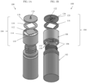
- FIGS. 1A and 1B illustrate top and bottom perspective views of an embodiment of a sample filtration device 100.
- the device 100 comprises a flexible container 102 and a cap 104.
- the flexible container 102 is configured to mate to the cap 104 using threads 106. Other mating mechanisms are also possible (e.g., snap fit, etc.).
- the flexible container 102 can comprise a cylindrical shape, but other shapes are also possible (e.g., ovular, spherical, square, etc.).
- the cap 104 comprises a cap housing 108.
- the filter mechanism is positioned at a top section of the cap 104.
- Inlet holes 110 allow sample fluid to enter the filter mechanism from the flexible container. Squeezing the flexible container can create a pressure gradient to urge the sample fluid through the inlet holes 110.
- Filter membrane 112 is positioned above inlet holes 110.
- the filter membrane 112 is shown as having a square shape, but other shapes are possible as long as they fit within the footprint of the ridge 114 of the cap housing 108.
- a double-sided adhesive layer 116 is positioned above the filter membrane 112.
- the adhesive layer 116 comprises a cut-out portion 118 configured to expose the filter membrane 112 and allow access to the support component 120 comprising mini-channels 122 and outlet 124, positioned above the adhesive layer 116.
- the mini-channels 122 are positioned on a bottom side of the support component 120, nearest to the filter membrane 112.
- An exit hole 126 in the channels leads to the outlet 124.
- the outlet 124 can comprise a spout feature.
- the cap 104 and flexible container 102 form a fluidic seal.
- the seal is formed at the interference of the perimeter 130 forming the opening of the flexible container and the flat surface 132 of the cap housing.
- the cap only allows fluid to flow through the inlet hole(s) 110 located on the cap housing 108 and into the filter assembly.
- the cap comprises only one opening to function properly, however multiple holes provide redundancy to prevent blockage caused by solids inside of the device. These solids might include clots, particulates, or items left inside the flexible container 102 by the user.
- the housing 108 also comprises a ridge 114 to facilitate assembly and self-centering. Furthermore, this ridge prevents users from tampering with the device by blocking access to the adhesive once assembled.
- the cap 104 can comprise materials that provide sufficient rigidity which include, but are not limited to, thermoplastics like polypropylene or polycarbonate or metals such as aluminum or steel.
- the face that interfaces with the filter stack up is substantially flat. That is, it is preferred that there exists no void, or spacing, or features between these faces.
- a flat design can provide ease in manufacturing.
- a void, or spacing, or proud features are placed between these faces. Such features can help to facilitate flow.
- FIGS. 2A-2C illustrate a detailed view of the filter membrane 202, the support component 204, and the double sided adhesive 206.
- the filter membrane 202 is positioned at the bottom.
- the double sided adhesive 206 is positioned above the filter membrane 202 and has an opening or cutout 208 in its center.
- the assembly Prior to sealing using the double sided adhesive 206, the assembly comprises a gap 210 between the double sided adhesive 206 and the cap housing 214 and surrounding the filter membrane 202, as shown in FIG. 2A .
- the adhesive 206 seals to the filter membrane 202 and the cap housing 214, eliminating or minimizing gap 210, as shown in FIG. 2B .
- pressurization e.g., squeezing of the flexible container
- a thin pocket 216 can form between the filter membrane 202 and the cap housing 214, shown in FIG. 2C .
- the double sided adhesive is a pressure sensitive adhesive and is meant to adhere to multiple surfaces when assembled. On one side, it mates only to the support component. On the other side, it mates with both the filter membrane(s) and the cap housing. In some applications, it may be desired to prevent deflection of the filter membrane upon pressurization (without pocket formation) by reversing the order in which the filters and the double sided adhesive are stacked. In this reversed configuration, on one side, the double sided adhesive mates with both the filter membrane and the rigid support component, and on the other side, the double sided adhesive mates with only the cap housing. Because this side mates with multiple surfaces, a double sided adhesive that is thicker than the compressed thickness of the filter membrane should be used to prevent excessive residual stresses on the support structure, which cause unbinding of the double sided adhesive.
- the double sided adhesive contains an inner cutout that has a perimeter that is smaller than the filter membrane's perimeter.
- the outer perimeter of the double sided adhesive preferably has a size that is smaller than the perimeter than the support component's perimeter; however, the double sided adhesive outer perimeter can be the same or larger than the support component and still function properly.
- the double sided adhesive prevents fluid from bypassing the filter membrane around the perimeter, thereby causing fluid to flow through the membrane, which ensures proper filtration behavior is achieved.
- the adhesion strength can be sufficient so that when the user operates the device by supplying pressure, the double sided adhesive does not delaminate from any of the surfaces it is adhered to.
- the thickness of the double sided adhesive should be chosen so that there is sufficient clearance for the filter membrane to allow lateral flow of the unfiltered sample mixture when pressurized. This lateral flow allows the entire filter area to be utilized for filtration.
- a substrate polymer film with double sided adhesive on each side can be used to account for the thickness necessary for the device to function.
- Another technique to account for the necessary thickness is to include a raised surface on the support component that accounts for the necessary thickness required for proper function.
- the adhesive can comprise, but is not limited to, silicone or acrylic based adhesives. To ensure that the double sided adhesive properly binds to all necessary surfaces, the assembly can be compressed together.
- the filter membrane can also compress, remain pinched, and seal at the edges by the adhesive.
- Other ways to seal the perimeter of the filter membrane include compression by ultrasonic welding. If the filter material is compatible with the cap housing or the support component, then the filter membrane can be directly ultrasonically welded to the surface of the housing or support component. Another technique can use an ultrasonic bond between the support component and the cap housing. This bond can apply a continuous pinching stress to seal the perimeter of the filter membrane. In addition to ultrasonic bonding, the same type of bond can be performed using a liquid adhesive.
- the filter membrane is a thin component that is placed in the center of the assembly.
- the filter membrane can be coated with chemicals or dry reagents.
- the filter membrane can be cut into virtually any size and shape. It is aligned so that the perimeter of the filter membrane resides outside of the perimeter of the inner cutout of the double sided adhesive to allow for proper sealing. Furthermore, the filter membrane's perimeter should reside within the outer perimeter of the double sided adhesive outer perimeter (shown best in FIG. 2A ) to permit the double sided adhesive to properly adhere to the support component.
- the filter can be about 15 mm by about 15 mm. Other dimensions are also possible.
- the filter can have a length of about 12-18 mm and a width of about 12-18 mm.
- the filter has a pore size of about 0.8 ⁇ m. Other pore sizes are also possible (e.g., 0.2 ⁇ m, 0.45 ⁇ m, 1.0 ⁇ m, 0.5 ⁇ m, etc.).
- using a 15 X 15 mm asymmetric filter with a pore size of 0.8 ⁇ m can produce enough sample to run a lateral flow immunoassay test at a 1:10 dilution of blood. This concentration can yield about 100 ⁇ L or 2-3 drops of processed sample to perform the assay.
- a typical lateral flow immunoassay test strip can run with about 50 ⁇ L or more of processed sample.
- the filtration capacity of the filter is directly related to the area of the exposed membrane and concentration of the biological sample mixture. Therefore, a variety of shapes and sizes can be used to accommodate different applications. If the filter membrane is an asymmetric filter, care should be taken so that its orientation is correct. That is, the side with larger pore sizes of the asymmetric filter should encounter the unfiltered sample first. This orientation is important so that the liquid should pass through the filter and exit the side containing small pores and trapping the biological particulates in the matrix of the asymmetric filter. These filter membranes can have pore sizes of varying diameter depending on the application. In some embodiments, other orientations are possible. Different filter membranes of different materials and styles can be used as well. These materials can comprise, but are not limited to polycarbonate, polysulfone, polyester, polyethylene, and polypropylene.
- a compound filter can include a second filter with a perimeter slightly smaller than the previously described filter, but still larger than the perimeter of the cutout in the double sided adhesive. The smaller filter is placed between the larger filter and the double sided adhesive. In this way, the adhesive binds to the perimeter of each filter membrane and seals each to ensure that fluid flows through the center of each filter instead of around the perimeter.
- This compound filter stack up design procedure can be performed indefinitely with more filters until the stack up becomes excessively thick or until the adhesive membrane can no longer seal to all of its intended surfaces.
- Another method to create a compound filter would be to use an additional array of both filter membrane and double sided adhesive in series to stack the filters in series.
- This additional array would be positioned between the output of the first filter membrane and the rigid support component. This allows for the creation of a filter with an indefinite number of filters in series. This process of stacking filters in series could potentially be done in combination with the previously mentioned method of using a slightly smaller filter to reduce the amount of double sided adhesive used.
- the support component comprises a thin walled piece that mates with the adhesive and the filter membrane. Its perimeter is shaped so that it fits inside of the ridge located on the cap housing to achieve proper alignment.
- the support component comprises mini-channels that extend throughout the area of the filter material. The number and size of mini-channels can be minimized to reduce the amount of dead volume of filtered product.
- the mini-channels provide a low resistance path for the filtrate to travel to the exit hole that is connected to a mini-channel. Enough mini-channels can be incorporated so that the entire area of the exposed membrane can have access to a low resistance path to the exit hole(s). While multiple mini-channels are most commonly used, a single, serpentine channel can cover the same area as the multiple channels.
- a spacing between channels is about 1.5 mm.
- Other spacing is also possible (e.g., 1-2 mm, 1-3 mm, 1-4 mm, 1 mm, 2 mm, 3 mm, etc.)
- the configuration of the channels can be selected based on the filter material and the roughness of the surface of the support component, as different filter materials will provide different levels of resistance for the product to travel to the nearest channel.
- a filter with smaller pores may have a smaller spacing between channels as compared to a filter with larger pores that provides a lower resistance path for the filtered product to travel to the channels.
- the exit hole(s) can reside in any location connected to a mini-channel.
- the exit hole(s) can also comprise a spout feature.
- the spout feature is designed to control the fluid deposition and collection. This spout allows for precise dispensing of the fluid into a variety of receiving devices.
- the shape of a spout feature can be a barb, a capillary, a tapered nozzle, or a simple tubular feature.
- the wall thickness of the support component should take into account its resistance to bending so that when the device is pressurized, it does not provide significant bending. This can be achieved through material selection or designing a component with appropriate thickness.
- the materials for this component can be, but are not limited to, thermoplastics, metals, and ceramics.
- the support component can also comprise a protective sheath that helps control the interface with the collection device. This is especially valuable when depositing a sample into a point of care device.
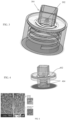
- a transparent sheath 304 shown in FIG. 3 , can be incorporated around the outlet 302 to prevent users from misaligning with the sample input area and ensure that full drops are formed instead of sometimes undesirably poured into the sample input area without forming full drops.
- the flexible container is configured to house fluids before they are passed through the filter assembly. It also provides a pressure when the operator squeezes it which will then drive fluid through the filter assembly.
- the pressure required to drive the fluid through the device can be as low as 1.724 kPa (0.25psi) and can reach pressures up to 34.474 kPa (5psi). If cell lysis is not desired, excessive pressure exceeding 34.474 kPa (5psi) are not be used for a blood sample, in some embodiments. An excessive driving pressure can cause cells to rupture and release intracellular content which may affect the result of the assay.
- the design of the flexible container is very similar to a generic squeeze bottle that contains threads at the top to mate with a cap.
- the materials to make the squeeze bottle can include, but are not limited to, high-density polyethylene, low-density polyethylene, polypropylene, and polyester.
- unfiltered fluid is inserted into the flexible container.
- the container could have a removable seal at its opening to contain a prefilled amount of fluid inside while stored. If prefilled fluids are not desired for the application, then the operator can add the unfiltered fluid. If mixing is needed, then the operator needs to mix by inducing relative motion in the fluid. This can be done by stirring, swirling, or shaking the fluid. If any contaminated tools such as stir rods, swabs, or collection devices are used, they can be disposed of in the flexible container to prevent scattered waste. Once the sample is prepared, the operator ensures that the cap is sealed, inverts the assembly and points the spout feature into the desired location.
- the squeeze action drives fluid through the hole(s) in the cap housing and laterally to the entire exposed area of the filter membrane.
- the driving pressure forms a pocket between the filter membrane and the cap housing by pressing the membrane down against the rigid support component to prevent excessive stretching and tearing of the filter membrane. If an asymmetric filter is used, then the fluid enters into the membrane through the large pores and the filtrate exits through the small pores. Otherwise, the fluid passes through the pores of a symmetric filter membrane. All trapped particles remain trapped by the filter membrane. If a compound filter is used, then the filtered sample will filter again through the next filter membrane.
- the filtrate then travels from the exit of the membrane to the mini-channel(s).
- the filtrate flows along the mini-channel(s) to the exit hole(s) located on the support component.
- the filtrate exits in the assembly through the spout feature and is collected according to the desired application.
- the size of the filter will need to be significantly larger than the opening of the flexible container.
- the complimentary threads 404 are resized to be significantly smaller than the size of the entire perimeter of the cap housing. By doing so, a designer could make a filter of any size and shape to fit with any flexible container of any size and shape as long as complimentary threads on the cap housing and the flexible container match.
- this assembly could be used with any pressure generating device.
- Other pressure generating devices include a syringe, a pump, gravity fed tubing, or a pressurized accumulator similar to a gas cylinder. Therefore, the attachment does not need to include threads.
- the assembly could be designed with an input barb to mate with a tube.
- a double barbed assembly would produce an in-line filter that could be used in a different type of application.
- the assembly could incorporate a Luer tapered connection to attach to a syringe that is loaded with the sample to filter.
- the filter could contain a flat surface to connect to a pressure sensitive adhesive.
- This design is not limited to the use with the flexible container; however the use of a flexible container demonstrates the capabilities of the filter as an easy-to-use device. Furthermore, the use of a flexible container allows for the precise control of the driving pressure to reduce the risk of cell lysis as a result of excessive pressurization, which could more easily occur with a syringe.
- a buffer solution is mixed with the unfiltered fluid prior to filtration.
- Phosphate buffered saline PBS
- Water can also be used; however, when using water, the osmotic pressure will drive excessive fluid into the cells and cause the cell membranes to rupture and release intracellular contents. This would include the hemoglobin and other intracellular components trapped in the cells, which would irreversibly dye the mixture a red color and release excessive protein into the sample mixture.
- lysis is desired if, for instance, DNA extraction from cells is required or to detect an intracellular biomarker. If lysis does occur, the filter can eliminate cell debris from the filtrate that may cause flowing problems in the assay.
- the buffer may contain surfactants mixed into PBS to improve flow down the strip.
- Common surfactants used are Tween-20 and Triton-X100, however, Triton X-100 might cause cell lysis. In some embodiments, these surfactants are found on the strips themselves so that the buffer does not need to include it.
- the buffer solution may contain animal protein to prevent the analyte of interest from binding to the background by competing in those areas.
- the buffer solution can also contain an anticoagulant like EDTA to prevent blood clots from forming in the mixture.
- the samples produced by the devices described herein can be used with any number of testing and diagnostic apparatuses, as the same principles could be used in all blood producing animal species including humans.
- protein detection using a lateral flow immunoassay (LFIA) test is contemplated.
- the devices can be used for testing that is not protein based.
- this device could be used to perform a blood alcohol content test, cannabinoid detection in blood for cannabis consumption, measure a vitamin deficiency, or use it to isolate cell free DNA that circulates in the blood stream.
- any analyte that circulates the bloodstream that is intercellular or intracellular can be tested by processing the blood with this device.
- Filtering a whole blood samples using the devices and methods described herein can allow for reliable at home or in the field testing using lateral flow immunoassay test strips.
- people are using whole blood directly on test strips to fill this need.
- the problem with applying whole blood directly on test strips is that the red color of the blood sample introduces background noise that interferes with detection of the colloidal gold or fluorescent test line used in many lateral flow immunoassay diagnostic tests. Filtering out the cells from the plasma keeps the test strip free of background noise and allows easy detection of the test line. Reliable at home blood testing can be helpful for testing for diseases such as HIV, which may still carry a stigma in certain locations.
- a single asymmetric filter can be used to measure an analyte that circulates the bloodstream in the plasma.
- a compound filter can be used to selectively lyse specific populations of cells.
- a rapid test for identifying sepsis-causing bacteria can work by detecting intracellular contents of the bacteria.
- a 2 stage compound filter can be used.
- the first filter can be an asymmetric membrane filter (Pall MMM series, or Vivid series, or BTS series, shown in FIG. 5 ) designed to trap all of the large red and white blood cells without lysis. Because bacteria are usually smaller than blood cells, they would pass through this filter since the pores would be larger than the bacteria.
- a membrane filter with very small pores can be used.
- a filter can be designed to not only stop the bacterial cells but also lyse them.
- the second filter is not asymmetric like the first filter so as to allow fluid to flow around them. Instead, it can be configured as a membrane with holes penetrating through it (Whatman Nuclepore track-etched membrane, shown in FIG. 6 ) and the driving pressure would rupture the cells.
- This type of filter design would selectively lyse a population of cells while keeping other populations intact based on size.
- Another application for such a filter is to detect other blood borne parasites like malaria. With this method the assembly could potentially detect the intracellular contents of small immature malaria cells by selectively lysing them.
- This device has the capability of processing a sample for both qualitative tests and quantitative tests, if known volumes of blood and buffer are inserted into the device.
- Qualitative tests provide a binary positive/negative result.
- qualitative tests that can be used with the devices herein include: detecting hCG hormone for pregnancy; detecting HIV antibody and/or surface antigen for HIV infection; detecting Hepatitis antibody and/or surface antigen for Hepatitis A/B/C infection or vaccination; detecting Herpes antibody for Herpes infection; detecting EIAV antibody for Equine infectious anemia in horses; detecting Heartworm antigen in dogs/cats for detecting heartworm disease; and detecting the presence of legal/illegal drugs in the bloodstream.
- the filtration device described herein can enable simple at home or in the field blood testing of HIV antibody earlier than current saliva based tests.
- the filtration device described herein can enable simple at home or in the field blood testing of hCG earlier than currently available home urine based tests.
- Quantitative tests provide a numerical value for the concentration of an analyte in the blood. This type of test is substantially more difficult to perform because it is critical to ensure that the volumes are properly collected and processed.
- a few examples of quantitative tests that can be used with the devices and methods described herein include measuring a sudden spike in Luteinizing Hormone for ovulation tracking; measuring an high concentration of H. Pylori antibody for ulcer diagnosis; measuring PSA concentration for prostate cancer screening; measuring Parathyroid hormone concentration for detecting a parathyroid adenoma; measuring HDL/LDL concentrations for monitoring cholesterol; and measuring Creatinine concentration for monitoring kidney function.
- quantitative tests employing a comparison of a test line to a control line can be enhanced using a smartphone application configured to compare the intensity of the lines.
- a quantitative test uses a swab configured to hold about 20-30 ⁇ L.
- a buffer solution used can provide a 1:10 dilution to ensure sufficient volume for the quantitative test.
- FIGS. 7A and 7B illustrate an example manufacturing process for components of the devices described herein.
- FIG. 7A shows an exploded side view of an output substrate 602 including outlet 604 or spout, a double sided adhesive 606, a filter 608 and an input substrate 610.
- a manufacturing process includes adhering a top side of the adhesive 606 to a bottom side of the output substrate 602.
- a bottom side of the adhesive 606 is adhered to a top side of the filter 608 and a top surface of the inner portion of the input substrate 610.
- most filters use ultrasonic welding so the manufacturing process time depends on plastic melting time, etc. In this case, the filter is manufactured using adhesive, so the manufacturing process can be much faster.
- sample filtration devices e.g., those described with respect to FIGS. 8A-17
- the flexible connector can be used to connect the filter to various sample collection and dispensing devices (including squeeze bottles).
- the flexible connector can allow for the use of the sample filtration device in many different types of applications including whole blood filtration.
- the flexibility in the material of the flexible connector can allow it to conform to different types of attachment features thus making it adaptable to many applications.
- the flexible connector described permits the use of conventional sample collection and dispensing devices to interface with it.
- These devices include, but are not limited to, bulb pipettes, micropipette tips, capillaries, syringe needles, barbs, squeeze bottles, tubes, and other devices with tubular or tapered interfacing geometries. In addition, it also can interface with noncircular geometries and components that contain manufacturing artifacts like parting lines and flash (e.g., bulb pipette, described below).
- FIGS. 8A-8C illustrate various views of an embodiment of a filter assembly 800 comprising a flexible connector 802 that can be used with the filter (e.g., the filters described herein).
- FIG. 8A shows a perspective view of a filter assembly flexible connector 802 attached to an input substrate 830 of the filter assembly. Beneath the input substrate 830 is an output substrate 832.
- the filter membrane 838 and double sided adhesive layer 836 are positioned between the input substrate 830 and the output substrate 832.
- the adhesive layer 836 and filter membrane 838 are in reverse order.
- the filter membrane 838 lies above or below the adhesive layer 836 while ensuring that the correct orientation of the filter membrane is preserved.
- the filter membrane comprises a length of about 17 mm and a width of about 17 mm. Other dimensions are also possible (e.g., width and/or length of about 15 mm, 16 mm, 17 mm, 15-20 mm, 10-15 mm, greater than 20 mm, etc.).
- the adhesive layer comprises a double sided pressure sensitive adhesive layer.
- the adhesive layer can comprise a pressure sensitive adhesive layer disposed on either side of a substrate (e.g., a PET substrate). Each adhesive layer can comprise a thickness of about 0.127mm (0.005").
- the substrate can comprise a thickness of about 0.127mm (0.005").
- Other dimensions are also possible (e.g., about 0.102 - 0.152mm (0.004-0.006"), about 0.076-0.178mm (0.003-0.007"), about 0.051 - 0.203mm (0.002-0.008"), about 0.102mm (0.004"), about 0.152mm (0.006”), etc.).
- the substrate can comprise a thickness of about 0.127mm (0.005").
- Other dimensions are also possible (e.g., about 0.102 - 0.152mm (0.004-0.006”), about 0.076-0.178mm (0.003-0.007”), about 0.051 - 0.203mm (0.002-0.008"), about 0.102mm (0.004"), about 0.152mm (0.006”), etc.).
- An adhesive layer with a 0.127mm (0.005") adhesive layer positioned on either side of a 0.127mm (0.005") substrate comprise a total thickness of about 0.381mm (0.015").
- This thickness leaves a very thin 0.051mm (0.002") gap with a filter membrane comprising dimensions of 17 mm x 17 mm, to permit fluid to flow laterally and wet the entire filter. It can be important to minimize this gap to ensure that enough pressure builds up in the assembly to drive the sample through the filter but still sufficient to permit fluid to flow laterally to reach the entire exposed filter membrane. Oversizing the gap can cause incomplete filtration of the sample due to insufficient drive pressure by introducing empty volume. If insufficient gap is present, then sample may encounter a restricted flow path to reach the entire exposed filter membrane. Proper design of this gap allows for the low volume of air dispensed by the pressurization device to ensure that the liquid sample is filtered completely.
- a 100-1000 ⁇ L micropipette typically can only dispense about 250 ⁇ L of air upon reaching the second stop of the plunger after dispensing the liquid volume. Minimizing this gap permits the use of low air volume dispensing devices, like a micropipette, to be used as a pressure source to properly drive the sample through the filter assembly completely.
- Other gap dimensions are also possible (e.g., about 1-3 mm, about 1 mm, about 3 mm, etc.).
- the adhesive layer can comprise a length and width of about 22 mm. Other lengths and widths are also possible (e.g., about 21 mm, about 23 mm, about 21-23 mm, about 20-24 mm, about 19-25 mm, about 15-25 mm, greater than 25 mm, etc.).
- the cutout in the adhesive layer can comprise a length and width of about 14 mm. Other lengths and widths are also possible (e.g., about 13 mm, about 15 mm, about 13-15 mm, about 11-17 mm, about 10-20 mm, etc.)
- one or both of the input substrate and the output substrate comprises polycarbonate.
- polycarbonate Other materials are also possible (e.g., polypropylene, polyethylene, and polystyrene.)
- Polycarbonate can advantageously be chemically compatible with the flexible connector material when it is being overmolded with a thermoplastic elastomer (TPE) with a durometer Shore 50A. This compatibility can ensure that the flexible connector material stays properly secured on the substrate and does not introduce leak paths.
- the input substrate can comprise a thickness of about 3 mm. Other dimensions are also possible (e.g., about 2 mm, about 4 mm, about 2-4 mm, about 1-5 mm, etc.).
- the input substrate can comprise a width and length of about 22 mm.
- a surface of the input substrate is flat to adhere to the double side adhesive.
- the surface of the input substrate comprises proud or textured features.
- the output substrate comprises a thickness of about 2 mm. This thickness can be sufficient to prevent bending during pressurization. Other thicknesses are also possible (e.g., about 1 mm, about 3 mm, about 1-3 mm, about 1-5 mm, etc.).
- the output substrate can comprise a length and width of about 22.25 mm.
- These dimensions can allow a 22 mm x 22 mm input substrate to fit within an area of the output substrate with the adhesive layer and filter membrane positioned between the input and output substrates.
- Other lengths and widths are also possible (e.g., about 21 mm, about 23 mm, about 21-23 mm, about 20-24 mm, about 19-25 mm, about 15-25 mm, greater than 25 mm, etc.)
- a funnel 804 can be included at the top of the flexible connector 802 to allow for easy attachment to the connector.
- the funnel 804 leads the attaching feature into the hole 806 (best shown in FIG. 8C ).
- the funnel comprises a large diameter of about 3.6 mm, a small diameter of about 1.6 mm, a chamfer angle of 45°, and a length of about 1 mm.
- Other dimensions are also possible.
- the large diameter can be about 3-4 mm, about 3 mm, about 4 mm, about 2-6 mm, etc.
- the small diameter can be about 1-2 mm, about 1 mm, about 2 mm, about 0-3 mm, etc.
- the chamfer angle can be about 40-50°, about 35-55°, about 30-60°, etc.
- the length of the funnel can be about 0.75-1.25 mm, about 0.5-1.5 mm, about 0.75 mm, about 1.25 mm, etc.)
- a narrow tube or pipe 808 After the chamfer of the funnel 804, is a narrow tube or pipe 808.
- This pipe can be long enough that it is able to grip and seal onto the attaching feature (e.g., the end of a pipette tip).
- the pipe can be about 7 mm high. Other lengths are also possible (e.g., about 5-7 mm, about 5 mm, about 6 mm, about 6-8 mm, about 5-9 mmm, about 7-8 mm, about 7-9 mm, etc.).
- the pipe can have a minimum inner diameter of about 1.5 mm. Other geometries are possible (e.g., about 1 mm, about 1-2 mm, about 2 mm, etc.).
- a pipe with a length of about 7 mm and a minimum inner diameter of about 1.5 mm can be configured to both grip and seal to a commercial 1000 ⁇ L pipette tip as well as many other inserted connecting features.
- the contracting hole 810 prevents further insertion into the assembly.
- This contracting hole 810 prevents damage to the filter membrane caused by overinsertion of the connecting male feature into the flexible connector.
- the contracting hole comprises a diameter of about 0.75 mm. Other diameters are also possible (e.g., about 0.7 mm, about 0.8 mm, about 0.6-0.9 mm, about 0.5-1 mm, etc.).
- the contracting hole 808 is sized smaller than the tip of the connecting feature (e.g., pipette) so that it comes to an abrupt stop once it encounters the contracting hole 808, but before it reaches the filter membrane.
- the flexible connector can comprise a flexible material including, but not limited to TPE, silicone, rubbers, polyurethane, and soft thermoplastics such as LDPE, HDPE, PP, and plasticized PVC.
- the wall thickness of the flexible connector is such that it provides enough rigid support when a connecting device attaches to the flexible connector so that it maintains alignment while still permitting for slight misalignments. It is also sized so that it can provide rigidity when inserting into a bore such as in the neck of a squeeze bottle. In some embodiments, the wall thickness is 2 mm. Other thicknesses are also possible (e.g., 1.5-2.5 mm, about 1.75 - 2.25 mm, about 1-3 mm, about 1-4 mm, etc.).
- an output feature 812 that directs the fluid into a desired location.
- the feature is sized so that it protrudes only slightly (e.g., about 2 mm, about 1-3 mm, about 1 mm, about 3 mm, greater than 3 mm, etc.). This allows for easy alignment and attachment to a commercial test cartridge, which can be a challenge in other available filter designs.
- the flat surface on the output side mates to the surface of a flat test cartridge so that the fluid is always directed perpendicularly into the cartridge.
- the small protrusion length and diameter of the output feature can provide clearance when residing in the sample input feature of a test cartridge.
- the outer diameter of the output feature can be about 1.25 mm.
- FIG. 8C illustrates an embodiment of a flexible connector 802 connected to an input substrate 830.
- the flexible connector comprises funnel portion 804, opening 806, pipe 808, and contracting hole 810.
- the embodiment of FIG. 8C differs from that shown in FIG. 8B as there is a larger cavity 811 beyond contracting hole that can be used to house a ball valve, as described in further detail below.
- FIG. 8D illustrates an embodiment of a filter assembly 850, similar to the assembly shown in FIG. 8C , but the flexible connector 852 of FIG. 8D includes an undercut 854 at the top of pipe 856. This undercut 854 can provide an audible snap when a barb is connected to the flexible connector. The undercut 854 can also hold the barb in place connected to the filter assembly.
- FIG. 8E illustrates another embodiment of a flexible connector 862 connected to an input substrate 864.
- the connector 862 and substrate 864 are connected using mechanical interlocks 864 which can help prevent the flexible connector from separating (e.g., peeling apart) from the input substrate.
- the filter assembly is formed as one piece or can be formed as separate pieces that are connected.
- the polycarbonate substrate can be injection molded and then physically placed onto another mold.
- the flexible connector material e.g., elastic TPE
- the flexible connector material can then be overmolded onto the substrate to create the flexible connector.
- the filter assembly 900 comprises a ball valve.
- the valve feature can address the back flow caused when an operator releases the activation action such as releasing a squeeze bottle or releasing the plunger of a micropipette.
- the filter assembly comprises flexible connector 902, funnel 904, opening 906, pipe 908, and contracting hole 910.
- the ball 914 rests in a cavity 916 that provides clearance and is disposed just past the contracting hole.
- One of the walls of the cavity is formed by the filter membrane 938 and the ball rests on the filter when it is not in use.
- the ball Upon activation of the pressurization action, the ball does not plug the cavity; however, upon release of the activating action, fluid will flow backwards.
- FIG. 9A shows the valve in an unsealed configuration with a fluid path around the ball 914 from the pipe 908 to the filter membrane 938
- FIG. 9B shows the valve in a sealed configuration with the ball 914 sealing the fluid path between the filter membrane 938 and the pipe 908.
- the ball can comprise different materials that include, but are not limited to rubbers, plastics, ceramics, and metals.
- a user can select a material with a density such that the ball will either float or sink depending on the orientation that the assembly is held.
- a material with a density such that the ball will either float or sink depending on the orientation that the assembly is held.
- a polypropylene (density ⁇ 0.9g/cm 3 ) material floats in water making it easier to seal in an upright orientation.
- a nitrile (density ⁇ 1.3g/cm 3 ) rubber ball will sink if the filter is held upside down making it a better sealing material in that orientation. The negative relative pressure generated by the pressurization device will then maintain the seal by creating a pressure differential on opposite sides of the ball, which seals the input, hole and prevents backflow.
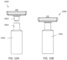
- FIGS. 10A-10B show how the flexible connector can be used to attach the filter assembly 1000 to a squeeze bottle 1006.
- the flexible connector 1002 can be inserted into and seal against the inside 1004 of the inner diameter of the bottle.
- the inner diameter of the bottle 1004 provides an interference with the connector once inserted and allows the device to be operated in as described above (e.g., in FIGS. 1A-1B ).
- the funnel feature of the flexible connector can be especially useful when attaching a micropipette tip to the flexible connector.
- a micropipette is held far away from the end of the pipette tip, so aiming the tip into the flexible connector is significantly more difficult without using a funneling feature as shown in the image.
- a filter assembly with a pipe that is about 7 mm high and has a minimum inner diameter of 1.5 mm can allow the flexible connector to both grip and seal to a commercial 1000 ⁇ L pipette tips as well as many other inserted connecting features.
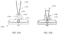
- FIGS. 11A-11B illustrate an example of a micropipette being used with the filter assembly 1100.
- a 100-1000 ⁇ L micropipette 1120 collects a sample (e.g., 100 ⁇ L) of whole blood.
- the tip 1122 is then inserted into the funnel 1104 of the flexible connector 1102.
- the flexible connector creates a fluidic seal on the tip, as shown in FIG. 11B .
- the connection between the connector and the micropipette also permits the entire assembly to be lifted and transported to the appropriate location for use.
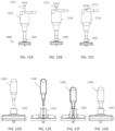
- FIGS. 12A-12C show a micropipette inserted into a filter assembly 1200, with the plunger of the micropipette depressed to various positions.
- FIG. 12A shows the micropipette 1210 inserted into the flexible connector 1202 prior to pressing of the plunger 1214.
- the plunger of a common lab micropipette has 2 stops. Depressing the plunger to the first stop, as shown in FIG. 12B , dispenses the contents of the pipette tip. Depressing the plunger to the second stop, as shown in FIG. 12C , ejects any remaining liquid by expelling air.
- FIG. 12A shows the micropipette 1210 inserted into the flexible connector 1202 prior to pressing of the plunger 1214.
- the plunger of a common lab micropipette has 2 stops. Depressing the plunger to the first stop, as shown in FIG. 12B , dispenses the contents of the pipette tip. Depressing the plunger to
- the micropipette is depressed up to the second stop using the expelled air as a source of pressure to apply on the blood to drive it through the filter.
- the user can release the plunger to release the pressure on the assembly.
- the plunger is held for 1 minute, but could be held for longer or shorter depending on the application.
- the same mode of operation can be used to filter diluted blood as well. Generally, diluted blood can be filtered faster since there are fewer cells to clog the filter. In some embodiments, diluted blood can be filtered by holding the plunger for about 5 s. In other embodiments, the plunger can be depressed for a shorter or longer amount of time when filtering diluted blood.
- a common lab micropipette 1210 can be easily adapted to filter diluted blood in addition to whole blood without the need of centrifugation using the filter assembly of the current application.
- the expelled air and liquid volume of a micropipette is a precise amount and can be used to provide a reliable pressure on the blood to filter the contents.
- a bulb pipette 1240 can be inserted into the flexible connector 1242.
- the design of the flexible connector can address the challenge posed by the parting line and flash of the bulb pipette introducing a leak path when sealing to other materials.
- the parting line no longer poses a problem for sample leakage. This is because the flexible property of the flexible connector allows it to seal on non-ideal surfaces. Molding flaws such as parting lines and flash introduce non-ideal sealing surfaces that pose problems with sealing against rigid or semi-rigid materials by introducing microscopic leak paths.
- the flexible material of the flexible connector is able to conform to the irregular and non-ideal surfaces and molding flaws to seal them and reduce the potential of undesired leaking.
- the filter assembly can be placed directly on a cartridge containing latch, or adhesive, or bonding features so that the assembly is secured in place while the cartridge is packaged by the test cartridge manufacturer.
- the user would be able to apply their preferred sample processing device (micropipette tip, bulb pipette, squeeze bottle with an appropriate male connector, etc.) directly on the cartridge.
- This mode of operation would remove the need for alignment because the fluid is delivered directly on to the sample input area of the cartridge after the processing device is secured in place.
- the flat nature of the design of the assembly allows for easy assembly and packaging.
- commercial filter assemblies contain long protruding features, which make them difficult to adapt into a cartridge.
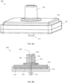
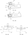
- FIGS. 13A-13B show perspective views of an embodiment of a filter assembly 1300 attaching to a cartridge 1302.
- FIG. 13A shows the filter assembly 1300 and cartridge 1302 prior to placing the assembly 1300 on the cartridge 1302.
- the cartridge 1302 comprises latch features 1304.
- the filter assembly can be properly positioned on the cartridge using aligners 1305 and latch features 1306 and snapped onto the cartridge with the protrusions 1306 of latch features 1304 securing the filter assembly in place.
- the aligners 1306 and latch features properly align the output of the filter assembly with the sample input area 1308 of the cartridge 1302 as shown in FIG. 13B.
- FIGS. 13C and 13D are side section views of filter assembly 1300 and cartridge 1302.
- the output feature 1312 of the filter assembly is seen in the side views of FIGS. 13C and 13D.
- FIG. 13C shows the filter assembly 1300 and cartridge 1302 prior to placement of the filter assembly 1300 on the cartridge 1302.
- FIG. 13D shows the filter assembly 1300 placed on the cartridge 1310 using aligners 1305 (not shown in FIG. 13D ) and latches 1304.
- FIGS. 13A-13D show the latches snapping onto the output substrate of the filter assemblies, but the latches can snap to the input substrate of the filter assembly in some embodiments.
- Other attachment mechanisms are also possible (e.g., Pressure sensitive adhesive, liquid adhesives, ultrasonic welding, crush ribs, crush pins, and press fits).
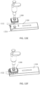
- FIGS. 13E and 13F show perspective views of a filter assembly 1300 being used with another embodiment of a cartridge 1320.
- FIG. 13E shows the filter assembly 1300 prior to placement on the cartridge 1320.
- the cartridge 1320 comprises aligners 1322, but the aligners do not comprise protrusions to form latches.
- the aligners can be used to properly position the filter assembly over the sample input area of the cartridge, as shown in FIG. 13F .
- the filter assembly can be aligned to the cartridge, the filtrate dispensed, and the filter assembly removed from the cartridge, so that the filter assembly and micropipette tip are disposed of separately from the cartridge.
- the filter assembly need not remain attached to the test cartridge.
- the aligners can be used in combination with a pressure sensitive adhesive or bonding agent to attach the filter assembly 1300 to the cartridge 1320.
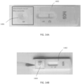
- FIG. 14A illustrates an embodiment of a commercial test cartridge 1402 and the location at which the filter assembly would be attached (e.g., the sample input area 1404).
- FIG. 14B shows the filter assembly 1400 attached to the cartridge 1402.
- the filter design can be assembled in an array for a multichannel micropipette or a robotic liquid handling station. This configuration can be especially useful to save time in the lab when multiple samples need to be processed at once.
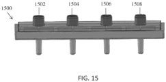
- FIG. 15 shows how the filter assembly can be adapted into an array where all four ports 1502, 1504, 1506, 1508 act independently from each other allowing different samples to be filtered independently without cross-contamination.
- Each port 1502, 1504, 1506, 1508 can comprise the flexible connector and filter assembly design described above.
- This design can be expanded to any number of filters in an array.
- the standard and ubiquitous 96 well plate format common across lab equipment has 9mm spacing between each of the pipette channels. The input channels can be spaced 9 mm apart or any multiple of 9 (9, 18, 27, etc.).
- FIGS. 16A-C depict other embodiments of a filter device utilizing a flexible container 1602 and cap 1604 design as described above (e.g., with respect to FIGS. 1A and 1B ).
- a swab 1606 can be included in the cap 1604 as shown in the cross section of FIG. 16A .
- the swab length is sized so that when the user begins to twist the cap 1604, the tip 1608 of the swab is pressed up against the inner wall of the squeeze bottle 1602.
- the swab 1606 is ideally made of a semi-rigid and bendable material and geometry so that it does not break when the forces are applied during the attachment of the cap 1604.
- the twist action of turning the threads 1610 of the cap on the threads 1612 of the bottle ensures that the cap is locked in place while also agitating the fluid so that the blood sample that is on the swab tip is mixed with the buffer solution inside of the bottle.
- the swab 1606 is secured onto the cap 1604 by including an undercut 1614 in the swab, shown best in the magnified view of FIG. 16B .
- This undercut 1614 snaps into place with complimentary mating features 1616 on the cap 1604. It is important that the cap is able to transmit a torque to the swab so that it rotates while turning. Therefore, the undercut comprises facets 1618 to permit the transmission of torque.
- the cap also includes complimentary facets 1620 to mate with the cap.
- the cap and swab must not create a fluidic seal when attached to permit the sample into the filter. Therefore, there can be a mismatch in geometry between the swab 1606 and the cap 1604.
- the hex flat to flat dimensions e.g., a distance between parallel facets of the hex
- the hex outer flat to flat dimensions 1624 exceed the hex outer flat to flat dimensions 1624 (by e.g., 0.051mm (0.002"), 0.025-0.051mm (0.001-0.002”), 0.025 - 2.54mm (0.001-0.1"), 0.025 - 0.127mm (0.001-0.005"), etc.
- the swab is snapped into place by pushing the latch features 1614 on the swab beyond the hex 1620 in the cap. These latch features ensure that the swab is held in place and cannot be easily pulled out. If the filter is placed on the test cartridge itself or if the application does not require filtration, then there will be no need for the filter on the cap and fluid will flow freely out once the device is squeezed.
- the above configuration demonstrates how to integrate the filter into this assembly, but a filter is not required when a test does not require sample filtration. Instead, this description depicts a method of mixing a sample of blood using a screw cap with the option to integrate with a filter design so that it can be dispensed as a filtered or unfiltered sample.
- FIG. 17 shows an assembly 1700 whose spiral mini-channel 1706 extends beyond the adhesive cutout perimeter 1702. Furthermore, after compressing the adhesive against the output component's sealing surface, the pressure sensitive adhesive creeps into the channels and seals them completely or partially. Thus, the lines 1702 representing the adhesive cutout perimeter are covered by the double sided adhesive layer (shown in white) and are not being used because the adhesive has blocked that length of the channel. Therefore, in this design, the usable portion of the filter that is being used is defined by the double sided adhesive layer.
- the shaded portion 1704 is the area of the filter membrane that is being used for filtration of a blood sample.
- This sealing by the adhesive allows a designer to specify a cutout area for the application without the need to redesign the rigid housing.
- This benefit permits the use of the same manufactured rigid housing components to be adaptable to function with many different applications with different volume and dilution requirements.
- This capability eliminates the need to design new and expensive tooling to reconfigure the filter to a new size footprint. Instead, the adhesive layer is converted to the appropriate size for the application, which is much simpler and cheaper to implement than creating new molds for a different application.
- typically sample processing includes using a precision pipette to collect a sample of blood from a vacutainer tube via venipuncture and depositing the sample into a centrifuge tube.
- a specific amount of buffer solution is then pipetted into the centrifuge tube with the blood sample.
- the mixture is then drawn into the pipette several times until it is homogeneous.
- the mixture is then centrifuged for a specified amount of time at high rotational speed.
- a specific amount of the supernatant is then pipetted onto the test strip.
- the volume of blood can be collected into a capillary, a swab, or pipetted.
- the device is agnostic to how the blood is collected.
- the blood can be mixed by swirling or stirring the mixture.
- the cells are separated from diluted plasma using a filter.
- the volume is deposited into the strip by counting drops or collecting a specified amount of sample.
- the devices and methods described herein take advantage of the scales that are reasonable for high volume manufacturing.
- the devices and methods work in dimensions and scales that can have devices components injection molded to reduce the cost significantly. Because of this, a mixing task can easily be performed by stirring, swirling, inverting, or repeat pipetting. At this scale, the device can utilize use a large filter at the cost of collecting slightly more sample volume (1-2 drops).
- the pressure source in this device is derived from simple actions such as a squeezing action of a flexible container or depressing a micropipette plunger. All of the sample processing steps are intuitive and do not require significant training to perform correctly.
- the filters that receive filtrate from the filter may be disposed on a thin film or other flimsy material. Additionally, the channels may be formed by laser etching or otherwise removing material from the layer, causing it to become even more flimsy. The flimsiness of the layer comprising the channels requires the channels to be adequately spaced apart to allow for deflection or compression of the layer, which could cause obstruction of any channels spaced too close to one another.
- the channels of the current design are provided on an inflexible or more rigid substrate that can be incapable of being bent. The rigidity of the substrate comprising the channels can allow for precise positioning of the channels. For example, the channels can be positioned very close to one another without concern for the channels becoming obstructed by deflection of the substrate. This capability can allow for a denser network of channels, providing faster and additional output capability of the filter.
- filters can also provide a design in which a buffer solution is provided within the filter and is passively mixed at some point within the filtering process.
- the dilution of the sample is dependent upon the configuration and geometry of the filter design.
- any buffer used is pre-mixed (e.g., in a flexible container) prior to applying the buffer and sample mixture to the filter. This pre-mixing allows the user to precisely select or calculate a desired dilution of the sample.
- filter designs lack a rigid substrate or housing providing stability to the filter.
- Such flexible designs are incapable of being easily placed on or attached (e.g., snapped) to a test cartridge.
- the filter designs of the current application include rigid substrates or housings.
- these flexible designs will deform upon pressurization due to the lack of rigidity and cause unwanted ballooning of the assembly.
- the rigidity of the substrate or housing can allow it to be easily placed on or snapped onto a test cartridge and maintain its form under pressurization.
Landscapes
- Health & Medical Sciences (AREA)
- Life Sciences & Earth Sciences (AREA)
- Chemical & Material Sciences (AREA)
- Engineering & Computer Science (AREA)
- Immunology (AREA)
- Biomedical Technology (AREA)
- Hematology (AREA)
- General Health & Medical Sciences (AREA)
- Physics & Mathematics (AREA)
- Analytical Chemistry (AREA)
- General Physics & Mathematics (AREA)
- Pathology (AREA)
- Biochemistry (AREA)
- Urology & Nephrology (AREA)
- Molecular Biology (AREA)
- Food Science & Technology (AREA)
- Medicinal Chemistry (AREA)
- Ecology (AREA)
- Chemical Kinetics & Catalysis (AREA)
- Biophysics (AREA)
- Clinical Laboratory Science (AREA)
- Biotechnology (AREA)
- Cell Biology (AREA)
- Microbiology (AREA)
- Sampling And Sample Adjustment (AREA)
- Investigating Or Analysing Biological Materials (AREA)
Applications Claiming Priority (2)
| Application Number | Priority Date | Filing Date | Title |
|---|---|---|---|
| US201762525039P | 2017-06-26 | 2017-06-26 | |
| PCT/US2018/039556 WO2019005833A1 (en) | 2017-06-26 | 2018-06-26 | SAMPLE FILTERING DEVICE |
Publications (3)
| Publication Number | Publication Date |
|---|---|
| EP3645998A1 EP3645998A1 (en) | 2020-05-06 |
| EP3645998A4 EP3645998A4 (en) | 2021-07-14 |
| EP3645998B1 true EP3645998B1 (en) | 2023-11-15 |
Family
ID=64741868
Family Applications (1)
| Application Number | Title | Priority Date | Filing Date |
|---|---|---|---|
| EP18823246.6A Active EP3645998B1 (en) | 2017-06-26 | 2018-06-26 | Sample filtration device and method |
Country Status (5)
| Country | Link |
|---|---|
| US (1) | US11946843B2 (zh) |
| EP (1) | EP3645998B1 (zh) |
| JP (1) | JP2020525802A (zh) |
| CN (1) | CN110785649A (zh) |
| WO (1) | WO2019005833A1 (zh) |
Families Citing this family (9)
| Publication number | Priority date | Publication date | Assignee | Title |
|---|---|---|---|---|
| US11612888B2 (en) | 2017-01-04 | 2023-03-28 | The Research Foundation For The State University Of New York | Biomarker detection device |
| US11596943B2 (en) * | 2018-07-25 | 2023-03-07 | Canon Virginia, Inc. | Multi hole inlet structure |
| USD920534S1 (en) | 2018-12-21 | 2021-05-25 | CanaryQ, Inc. | Blood sample filtration device |
| CN112858085B (zh) * | 2021-01-19 | 2021-11-02 | 竹简云(天津)生物科技有限公司 | 一种食品药物溶解度检测分析装置 |
| CN113252765B (zh) * | 2021-06-21 | 2021-09-14 | 南昌大学 | 毛细管电泳仪 |
| WO2023114978A1 (en) | 2021-12-17 | 2023-06-22 | Abbott Laboratories | Systems and methods for determining uch-l1, gfap, and other biomarkers in blood samples |
| CN114323803B (zh) * | 2022-03-08 | 2022-05-20 | 潍坊市奎文区园林环卫服务中心 | 一种园林生态管理用水质取样装置 |
| WO2024006876A1 (en) | 2022-06-29 | 2024-01-04 | Abbott Laboratories | Magnetic point-of-care systems and assays for determining gfap in biological samples |
| CN115950868B (zh) * | 2022-12-26 | 2024-02-13 | 深圳市雷诺华科技实业有限公司 | 一种抗体-斑点法进行糖化白蛋白测定的测试装置及其测试方法 |
Family Cites Families (49)
| Publication number | Priority date | Publication date | Assignee | Title |
|---|---|---|---|---|
| US3939822A (en) | 1974-08-14 | 1976-02-24 | Jack Markowitz | Disposable blood collection and filtering device |
| BE849898A (fr) | 1976-12-28 | 1977-06-28 | Dispositif de dilution et de filtration | |
| DE3037898A1 (de) | 1980-10-07 | 1982-05-06 | Bruker Analytische Meßtechnik GmbH, 7512 Rheinstetten | Mischkammer |
| US4915847A (en) | 1987-08-04 | 1990-04-10 | Baxter International Inc. | Cryoglobulin separation |
| USD305934S (en) | 1986-11-27 | 1990-02-06 | Terumo Kabushiki Kaisha | Filter for treating blood |
| US4828716A (en) | 1987-04-03 | 1989-05-09 | Andronic Devices, Ltd. | Apparatus and method for separating phases of blood |
| US4761230A (en) | 1987-06-11 | 1988-08-02 | Millipore Corporation | Small volume tangential flow filtration apparatus |
| NL8800796A (nl) * | 1988-03-29 | 1989-10-16 | X Flow Bv | Werkwijze voor de chemische analyse van bestanddelen van een lichaamsvloeistof, alsmede een testinrichting en testpakket voor een dergelijke analyse. |
| US4976851A (en) | 1988-06-06 | 1990-12-11 | Terumo Kabushiki Kaisha | Liquid separator |
| GB2232599A (en) | 1989-06-08 | 1990-12-19 | Summers Dr Julie Andrea | One-step blood to plasma device |
| USD355973S (en) | 1993-02-10 | 1995-02-28 | Terumo Kabushiki Kaisha | Blood filter |
| JPH09196911A (ja) * | 1996-01-19 | 1997-07-31 | Fuji Photo Film Co Ltd | 血液濾過ユニット |
| ES2182022T3 (es) | 1996-02-09 | 2003-03-01 | Micro Diagnostic Innovations N | Metodo y equipo para separar el plasma de la sangre total. |
| USD403975S (en) | 1997-06-17 | 1999-01-12 | Mercury Diagnostics, Inc. | Test strip device |
| US7745106B2 (en) | 1997-06-24 | 2010-06-29 | Cascade Medical Enterprises, Llc | Methods and devices for separating liquid components |
| JP2000074906A (ja) | 1998-09-01 | 2000-03-14 | Fuji Photo Film Co Ltd | 簡易血液濾過点着器 |
| CA2374423C (en) * | 1999-05-28 | 2013-04-09 | Cepheid | Apparatus and method for analyzing a liquid sample |
| JP2001299730A (ja) | 2000-04-21 | 2001-10-30 | Fuji Photo Film Co Ltd | 血漿採取具 |
| US20020058030A1 (en) | 2000-05-03 | 2002-05-16 | Eligix, Inc. | Whole blood separator apparatus and method of use |
| JP2001321368A (ja) | 2000-05-16 | 2001-11-20 | Fuji Photo Film Co Ltd | 血漿採取具 |
| US6632681B1 (en) | 2000-07-24 | 2003-10-14 | Ey Laboratories | Reagent delivery device and method of use |
| DE60211140T2 (de) * | 2001-02-06 | 2007-02-01 | Pall Corp. | Filtrationsgerät |
| AU151377S (en) | 2002-06-10 | 2003-04-04 | Daiichi Pure Chemicals Co Ltd | Device for test of specimen |
| US7093507B2 (en) | 2003-05-12 | 2006-08-22 | Bel-Art Products, Inc. | Pipette control arrangement |
| JP2006118936A (ja) | 2004-10-20 | 2006-05-11 | Denka Seiken Co Ltd | メンブランエンザイムイムノアッセイ法 |
| USD566291S1 (en) | 2005-05-03 | 2008-04-08 | Handylab, Inc. | Microfluidic cartridge |
| GB0900176D0 (en) * | 2009-01-08 | 2009-02-11 | Campbell James G | Detection system apparatus and method |
| KR20100111097A (ko) | 2009-04-06 | 2010-10-14 | 삼성전자주식회사 | 표적물질 분리를 위한 미세유동장치 및 그 정제방법 |
| EP2264453B1 (en) | 2009-06-17 | 2013-04-03 | Leukocare Ag | Method for filtering blood |
| USD642908S1 (en) | 2009-11-17 | 2011-08-09 | Help Remedies, Inc. | Container |
| CA2785390C (en) | 2009-12-23 | 2016-02-09 | Cytovera, Inc. | A system and method for particle filtration |
| AU2013204820B2 (en) * | 2009-12-23 | 2014-01-30 | Cytovera, Inc. | A System and Method for Particle Filtration |
| US8388566B2 (en) | 2010-04-29 | 2013-03-05 | Sorin Group Italia, S.r.l. | Oxygenator with integrated arterial filter including filter frame |
| WO2011155897A1 (en) | 2010-06-10 | 2011-12-15 | Hemcheck Sweden Aktiebolag | Arrangement for detection of hemolysis |
| EP2593768A1 (en) | 2010-07-14 | 2013-05-22 | Qiagen GmbH | New storage, collection or isolation device |
| KR101749243B1 (ko) * | 2010-12-06 | 2017-06-21 | 한국전자통신연구원 | 자기력을 이용한 혈장 분리 방법 및 장치 |
| SE536634C2 (sv) | 2011-12-09 | 2014-04-15 | Hemcheck Sweden Ab | Anordning för detektion av hemolys |
| CN104066514B (zh) | 2012-01-24 | 2017-07-28 | 皇家飞利浦有限公司 | 用于筒的过滤单元 |
| DE202013012535U1 (de) * | 2012-02-13 | 2017-08-28 | Streck Inc. | Blutsammelvorrichtung für verbesserte Nukleinsäureregulierung |
| CN105874052B (zh) * | 2013-11-04 | 2019-05-21 | 查尔斯河实验室公司 | 过滤系统和其使用 |
| USD734467S1 (en) | 2014-03-24 | 2015-07-14 | Fenwal, Inc. | Blood filter |
| US10111610B2 (en) | 2014-11-04 | 2018-10-30 | Wainamics, Inc. | Microscale plasma separator |
| USD771833S1 (en) | 2015-04-28 | 2016-11-15 | University Of British Columbia | Microfluidic cartridge |
| USD772427S1 (en) | 2015-04-28 | 2016-11-22 | University Of British Columbia | Microfluidic cartridge |
| USD771834S1 (en) | 2015-04-28 | 2016-11-15 | University Of British Columbia | Microfluidic cartridge |
| ES2740998T3 (es) | 2016-07-19 | 2020-02-07 | Evonik Operations Gmbh | Ligandos de 1,1'-bis(fosfino)ferroceno para alcoxicarbonilación |
| DE102017125881B4 (de) | 2017-11-06 | 2019-06-19 | Sartorius Stedim Biotech Gmbh | Filtermodul und Verfahren zum Nachweis von Mirkoorganismen |
| JP1610170S (zh) | 2017-11-10 | 2018-07-30 | ||
| USD875271S1 (en) | 2018-08-03 | 2020-02-11 | Vdi Laboratory, Llc. | Collection and storage case for dry blood samples |
-
2018
- 2018-06-26 US US16/625,799 patent/US11946843B2/en active Active
- 2018-06-26 WO PCT/US2018/039556 patent/WO2019005833A1/en unknown
- 2018-06-26 CN CN201880042213.7A patent/CN110785649A/zh active Pending
- 2018-06-26 EP EP18823246.6A patent/EP3645998B1/en active Active
- 2018-06-26 JP JP2020520436A patent/JP2020525802A/ja active Pending
Also Published As
| Publication number | Publication date |
|---|---|
| US11946843B2 (en) | 2024-04-02 |
| CN110785649A (zh) | 2020-02-11 |
| JP2020525802A (ja) | 2020-08-27 |
| WO2019005833A1 (en) | 2019-01-03 |
| US20200124508A1 (en) | 2020-04-23 |
| EP3645998A1 (en) | 2020-05-06 |
| EP3645998A4 (en) | 2021-07-14 |
Similar Documents
| Publication | Publication Date | Title |
|---|---|---|
| EP3645998B1 (en) | Sample filtration device and method | |
| US10589265B2 (en) | Reagent storage in microfluidic systems and related articles and methods | |
| JP4513085B2 (ja) | 試料の容器 | |
| US7870964B2 (en) | Implementation of microfluidic components in a microfluidic system | |
| US10111610B2 (en) | Microscale plasma separator | |
| CN111282607B (zh) | 用于样品流体分析的一次性盒 | |
| US20190201889A1 (en) | Aspiration-free well plate apparatus and methods | |
| US20210231643A1 (en) | Vacuum-assisted plasma separation | |
| CA2320296A1 (en) | Liquid analysis cartridge | |
| JP2020525802A5 (zh) | ||
| US20210387198A1 (en) | Easy-disconnect seal matching reservoir and holder platform for microfluidic chip | |
| US11305236B2 (en) | Surface tension driven filtration | |
| MXPA01000691A (es) | Extraccion mediante un fluido de muestras microdisectadas. | |
| CN1331575C (zh) | 微射流系统中的微射流部件的实现 | |
| WO2019168835A1 (en) | Devices and methods for sample analysis with serial dilution | |
| CN214334446U (zh) | 全血过滤芯片 | |
| WO2023161619A1 (en) | Integrated microfluidic test strip | |
| KR20240042957A (ko) | 현장진단을 위한 혈액 분리 바이오칩 | |
| WO2005031163A1 (en) | Implementation of microfluidic components in a microfluidic system |
Legal Events
| Date | Code | Title | Description |
|---|---|---|---|
| STAA | Information on the status of an ep patent application or granted ep patent |
Free format text: STATUS: THE INTERNATIONAL PUBLICATION HAS BEEN MADE |
|
| PUAI | Public reference made under article 153(3) epc to a published international application that has entered the european phase |
Free format text: ORIGINAL CODE: 0009012 |
|
| STAA | Information on the status of an ep patent application or granted ep patent |
Free format text: STATUS: REQUEST FOR EXAMINATION WAS MADE |
|
| 17P | Request for examination filed |
Effective date: 20200107 |
|
| AK | Designated contracting states |
Kind code of ref document: A1 Designated state(s): AL AT BE BG CH CY CZ DE DK EE ES FI FR GB GR HR HU IE IS IT LI LT LU LV MC MK MT NL NO PL PT RO RS SE SI SK SM TR |
|
| AX | Request for extension of the european patent |
Extension state: BA ME |
|
| DAV | Request for validation of the european patent (deleted) | ||
| DAX | Request for extension of the european patent (deleted) | ||
| A4 | Supplementary search report drawn up and despatched |
Effective date: 20210615 |
|
| RIC1 | Information provided on ipc code assigned before grant |
Ipc: G01N 1/28 20060101AFI20210608BHEP Ipc: G01N 33/483 20060101ALI20210608BHEP Ipc: G01N 33/487 20060101ALI20210608BHEP Ipc: G01N 33/49 20060101ALI20210608BHEP Ipc: G01N 33/50 20060101ALI20210608BHEP Ipc: G01N 33/53 20060101ALI20210608BHEP Ipc: G01N 33/82 20060101ALI20210608BHEP Ipc: G01N 33/98 20060101ALI20210608BHEP Ipc: G01N 35/00 20060101ALI20210608BHEP Ipc: G01N 37/00 20060101ALI20210608BHEP Ipc: B01L 3/00 20060101ALI20210608BHEP Ipc: G01N 1/40 20060101ALI20210608BHEP Ipc: G01N 33/543 20060101ALI20210608BHEP Ipc: G01N 33/558 20060101ALI20210608BHEP Ipc: G01N 35/10 20060101ALI20210608BHEP |
|
| GRAP | Despatch of communication of intention to grant a patent |
Free format text: ORIGINAL CODE: EPIDOSNIGR1 |
|
| STAA | Information on the status of an ep patent application or granted ep patent |
Free format text: STATUS: GRANT OF PATENT IS INTENDED |
|
| INTG | Intention to grant announced |
Effective date: 20230306 |
|
| GRAS | Grant fee paid |
Free format text: ORIGINAL CODE: EPIDOSNIGR3 |
|
| GRAA | (expected) grant |
Free format text: ORIGINAL CODE: 0009210 |
|
| STAA | Information on the status of an ep patent application or granted ep patent |
Free format text: STATUS: THE PATENT HAS BEEN GRANTED |
|
| P01 | Opt-out of the competence of the unified patent court (upc) registered |
Effective date: 20230926 |
|
| AK | Designated contracting states |
Kind code of ref document: B1 Designated state(s): AL AT BE BG CH CY CZ DE DK EE ES FI FR GB GR HR HU IE IS IT LI LT LU LV MC MK MT NL NO PL PT RO RS SE SI SK SM TR |
|
| REG | Reference to a national code |
Ref country code: CH Ref legal event code: EP Ref country code: GB Ref legal event code: FG4D |
|
| REG | Reference to a national code |
Ref country code: DE Ref legal event code: R096 Ref document number: 602018061209 Country of ref document: DE |
|
| REG | Reference to a national code |
Ref country code: IE Ref legal event code: FG4D |
|
| REG | Reference to a national code |
Ref country code: LT Ref legal event code: MG9D |
|
| REG | Reference to a national code |
Ref country code: NL Ref legal event code: MP Effective date: 20231115 |
|
| PG25 | Lapsed in a contracting state [announced via postgrant information from national office to epo] |
Ref country code: GR Free format text: LAPSE BECAUSE OF FAILURE TO SUBMIT A TRANSLATION OF THE DESCRIPTION OR TO PAY THE FEE WITHIN THE PRESCRIBED TIME-LIMIT Effective date: 20240216 |
|
| PG25 | Lapsed in a contracting state [announced via postgrant information from national office to epo] |
Ref country code: IS Free format text: LAPSE BECAUSE OF FAILURE TO SUBMIT A TRANSLATION OF THE DESCRIPTION OR TO PAY THE FEE WITHIN THE PRESCRIBED TIME-LIMIT Effective date: 20240315 |
|
| PG25 | Lapsed in a contracting state [announced via postgrant information from national office to epo] |
Ref country code: LT Free format text: LAPSE BECAUSE OF FAILURE TO SUBMIT A TRANSLATION OF THE DESCRIPTION OR TO PAY THE FEE WITHIN THE PRESCRIBED TIME-LIMIT Effective date: 20231115 |
|
| REG | Reference to a national code |
Ref country code: AT Ref legal event code: MK05 Ref document number: 1632189 Country of ref document: AT Kind code of ref document: T Effective date: 20231115 |
|
| PG25 | Lapsed in a contracting state [announced via postgrant information from national office to epo] |
Ref country code: NL Free format text: LAPSE BECAUSE OF FAILURE TO SUBMIT A TRANSLATION OF THE DESCRIPTION OR TO PAY THE FEE WITHIN THE PRESCRIBED TIME-LIMIT Effective date: 20231115 |
|
| PG25 | Lapsed in a contracting state [announced via postgrant information from national office to epo] |
Ref country code: AT Free format text: LAPSE BECAUSE OF FAILURE TO SUBMIT A TRANSLATION OF THE DESCRIPTION OR TO PAY THE FEE WITHIN THE PRESCRIBED TIME-LIMIT Effective date: 20231115 |
|
| PG25 | Lapsed in a contracting state [announced via postgrant information from national office to epo] |
Ref country code: ES Free format text: LAPSE BECAUSE OF FAILURE TO SUBMIT A TRANSLATION OF THE DESCRIPTION OR TO PAY THE FEE WITHIN THE PRESCRIBED TIME-LIMIT Effective date: 20231115 |
|
| PG25 | Lapsed in a contracting state [announced via postgrant information from national office to epo] |
Ref country code: NL Free format text: LAPSE BECAUSE OF FAILURE TO SUBMIT A TRANSLATION OF THE DESCRIPTION OR TO PAY THE FEE WITHIN THE PRESCRIBED TIME-LIMIT Effective date: 20231115 Ref country code: LT Free format text: LAPSE BECAUSE OF FAILURE TO SUBMIT A TRANSLATION OF THE DESCRIPTION OR TO PAY THE FEE WITHIN THE PRESCRIBED TIME-LIMIT Effective date: 20231115 Ref country code: IS Free format text: LAPSE BECAUSE OF FAILURE TO SUBMIT A TRANSLATION OF THE DESCRIPTION OR TO PAY THE FEE WITHIN THE PRESCRIBED TIME-LIMIT Effective date: 20240315 Ref country code: GR Free format text: LAPSE BECAUSE OF FAILURE TO SUBMIT A TRANSLATION OF THE DESCRIPTION OR TO PAY THE FEE WITHIN THE PRESCRIBED TIME-LIMIT Effective date: 20240216 Ref country code: ES Free format text: LAPSE BECAUSE OF FAILURE TO SUBMIT A TRANSLATION OF THE DESCRIPTION OR TO PAY THE FEE WITHIN THE PRESCRIBED TIME-LIMIT Effective date: 20231115 Ref country code: BG Free format text: LAPSE BECAUSE OF FAILURE TO SUBMIT A TRANSLATION OF THE DESCRIPTION OR TO PAY THE FEE WITHIN THE PRESCRIBED TIME-LIMIT Effective date: 20240215 Ref country code: AT Free format text: LAPSE BECAUSE OF FAILURE TO SUBMIT A TRANSLATION OF THE DESCRIPTION OR TO PAY THE FEE WITHIN THE PRESCRIBED TIME-LIMIT Effective date: 20231115 Ref country code: PT Free format text: LAPSE BECAUSE OF FAILURE TO SUBMIT A TRANSLATION OF THE DESCRIPTION OR TO PAY THE FEE WITHIN THE PRESCRIBED TIME-LIMIT Effective date: 20240315 |