EP3645374B1 - Système de direction à commande par câble électrique à vectorisation de couple et régulation antipatinage intégrée - Google Patents
Système de direction à commande par câble électrique à vectorisation de couple et régulation antipatinage intégrée Download PDFInfo
- Publication number
- EP3645374B1 EP3645374B1 EP18748857.2A EP18748857A EP3645374B1 EP 3645374 B1 EP3645374 B1 EP 3645374B1 EP 18748857 A EP18748857 A EP 18748857A EP 3645374 B1 EP3645374 B1 EP 3645374B1
- Authority
- EP
- European Patent Office
- Prior art keywords
- speed
- wheel
- soll
- steerable wheels
- wheels
- Prior art date
- Legal status (The legal status is an assumption and is not a legal conclusion. Google has not performed a legal analysis and makes no representation as to the accuracy of the status listed.)
- Active
Links
- 238000000034 method Methods 0.000 claims description 12
- 238000009987 spinning Methods 0.000 description 2
- 238000010586 diagram Methods 0.000 description 1
- 230000000694 effects Effects 0.000 description 1
- 230000002093 peripheral effect Effects 0.000 description 1
Images

Classifications
-
- B—PERFORMING OPERATIONS; TRANSPORTING
- B62—LAND VEHICLES FOR TRAVELLING OTHERWISE THAN ON RAILS
- B62D—MOTOR VEHICLES; TRAILERS
- B62D9/00—Steering deflectable wheels not otherwise provided for
- B62D9/002—Steering deflectable wheels not otherwise provided for combined with means for differentially distributing power on the deflectable wheels during cornering
-
- B—PERFORMING OPERATIONS; TRANSPORTING
- B62—LAND VEHICLES FOR TRAVELLING OTHERWISE THAN ON RAILS
- B62D—MOTOR VEHICLES; TRAILERS
- B62D11/00—Steering non-deflectable wheels; Steering endless tracks or the like
- B62D11/02—Steering non-deflectable wheels; Steering endless tracks or the like by differentially driving ground-engaging elements on opposite vehicle sides
- B62D11/06—Steering non-deflectable wheels; Steering endless tracks or the like by differentially driving ground-engaging elements on opposite vehicle sides by means of a single main power source
- B62D11/10—Steering non-deflectable wheels; Steering endless tracks or the like by differentially driving ground-engaging elements on opposite vehicle sides by means of a single main power source using gearings with differential power outputs on opposite sides, e.g. twin-differential or epicyclic gears
-
- B—PERFORMING OPERATIONS; TRANSPORTING
- B60—VEHICLES IN GENERAL
- B60L—PROPULSION OF ELECTRICALLY-PROPELLED VEHICLES; SUPPLYING ELECTRIC POWER FOR AUXILIARY EQUIPMENT OF ELECTRICALLY-PROPELLED VEHICLES; ELECTRODYNAMIC BRAKE SYSTEMS FOR VEHICLES IN GENERAL; MAGNETIC SUSPENSION OR LEVITATION FOR VEHICLES; MONITORING OPERATING VARIABLES OF ELECTRICALLY-PROPELLED VEHICLES; ELECTRIC SAFETY DEVICES FOR ELECTRICALLY-PROPELLED VEHICLES
- B60L15/00—Methods, circuits, or devices for controlling the traction-motor speed of electrically-propelled vehicles
- B60L15/20—Methods, circuits, or devices for controlling the traction-motor speed of electrically-propelled vehicles for control of the vehicle or its driving motor to achieve a desired performance, e.g. speed, torque, programmed variation of speed
- B60L15/2036—Electric differentials, e.g. for supporting steering vehicles
-
- B—PERFORMING OPERATIONS; TRANSPORTING
- B62—LAND VEHICLES FOR TRAVELLING OTHERWISE THAN ON RAILS
- B62D—MOTOR VEHICLES; TRAILERS
- B62D5/00—Power-assisted or power-driven steering
- B62D5/001—Mechanical components or aspects of steer-by-wire systems, not otherwise provided for in this maingroup
- B62D5/005—Mechanical components or aspects of steer-by-wire systems, not otherwise provided for in this maingroup means for generating torque on steering wheel or input member, e.g. feedback
- B62D5/006—Mechanical components or aspects of steer-by-wire systems, not otherwise provided for in this maingroup means for generating torque on steering wheel or input member, e.g. feedback power actuated
-
- Y—GENERAL TAGGING OF NEW TECHNOLOGICAL DEVELOPMENTS; GENERAL TAGGING OF CROSS-SECTIONAL TECHNOLOGIES SPANNING OVER SEVERAL SECTIONS OF THE IPC; TECHNICAL SUBJECTS COVERED BY FORMER USPC CROSS-REFERENCE ART COLLECTIONS [XRACs] AND DIGESTS
- Y02—TECHNOLOGIES OR APPLICATIONS FOR MITIGATION OR ADAPTATION AGAINST CLIMATE CHANGE
- Y02T—CLIMATE CHANGE MITIGATION TECHNOLOGIES RELATED TO TRANSPORTATION
- Y02T10/00—Road transport of goods or passengers
- Y02T10/60—Other road transportation technologies with climate change mitigation effect
- Y02T10/64—Electric machine technologies in electromobility
-
- Y—GENERAL TAGGING OF NEW TECHNOLOGICAL DEVELOPMENTS; GENERAL TAGGING OF CROSS-SECTIONAL TECHNOLOGIES SPANNING OVER SEVERAL SECTIONS OF THE IPC; TECHNICAL SUBJECTS COVERED BY FORMER USPC CROSS-REFERENCE ART COLLECTIONS [XRACs] AND DIGESTS
- Y02—TECHNOLOGIES OR APPLICATIONS FOR MITIGATION OR ADAPTATION AGAINST CLIMATE CHANGE
- Y02T—CLIMATE CHANGE MITIGATION TECHNOLOGIES RELATED TO TRANSPORTATION
- Y02T10/00—Road transport of goods or passengers
- Y02T10/60—Other road transportation technologies with climate change mitigation effect
- Y02T10/72—Electric energy management in electromobility
Definitions
- the present invention relates to a steer-by-wire steering system of a motor vehicle having the features of the preamble of claim 1 and a method for controlling a steer-by-wire steering system of a motor vehicle having the features of the preamble of claim 5.
- the position of the steered wheels is not directly coupled to the steering input means, such as a steering wheel.
- the steering input means such as a steering wheel.
- the driver's steering request is picked up by a steering angle sensor, and depending on the driver's steering request, the position of the steered wheels is controlled via a steering actuator.
- the DE 10 2013 011 883 A1 discloses a method in which a target steering angle is calculated using a steering wheel rotation angle and an actual steering angle is provided by the vehicle wheels.
- the wheel drive torques for the left and right wheels are determined in such a way that the difference between the desired and actual steering angles is reduced.
- This solution proves to be disadvantageous in that wheel spin is not taken into account.
- the DE 10 2008 049 992 A1 is considered to be the closest prior art to the subject-matter of the independent claims and discloses a motor vehicle steering apparatus having two drive means for drive wheels which are adjustable by a steering angle for steering action.
- the drive means can be controlled via a drive unit in such a way that they have different drive torques.
- the drive unit adjusts the drive torques as a function of a steering value.
- a method for avoiding slip by means of torque vectoring is also to be specified.
- a steer-by-wire steering system for a motor vehicle with a steerable front wheel axle having two steerable wheels, the front wheel axle having an individual wheel drive which drives wheel drives assigned to the steerable wheels individually by means of a drive controller, the drive controller having a controller the in Depending on an accelerator pedal angle and a rotation angle of a steering shaft, a target speed for a left wheel of the steerable wheels and a target speed for a right wheel of the steerable wheels are determined and these are limited to a slip-limited speed, with the drive controller driving the wheel drives individually in such a way that the difference between Target speed and actual speed for each steerable wheel is minimal. This prevents the front wheels from spinning and the vehicle from being accelerated not only by the steering. A reduction in slip is enhanced, where loss of traction and cornering can be restrained. At the same time, driving dynamics and driving safety increase.
- the limitation to the slip-limited speed preferably takes place by means of a predefined maximum permissible longitudinal slip and an average vehicle speed measured at a rear axle of the motor vehicle.
- the maximum permissible longitudinal slip is advantageously in a range from 5% to 15% of the average vehicle speed measured at the rear axle, preferably around 10%.
- wheel drives are electric motors.
- the drive torque for the steerable wheels is thus set in such a way that the difference between the target and actual speed of the front wheels is minimized and the vehicle is thereby steered within the specified slip range at every accelerator pedal and steering wheel angle of the steering shaft.
- the limitation to the slip-limited speed preferably takes place by means of a predefined maximum permissible longitudinal slip and an average vehicle speed measured at a rear axle.
- the maximum permissible longitudinal slip is in a range of 5% to 15% of the average vehicle speed measured at the rear axle, preferably 10%.
- the limitation of the set speeds to the average speed measured at the rear axle preferably takes into account the maximum permissible longitudinal slip.
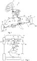
- a steer-by-wire steering system 1 is shown.
- a rotation angle sensor (not shown) is attached to a steering shaft 2, which detects the driver's steering angle applied by turning a steering input means 3, which is designed as a steering wheel in the example.
- a steering torque can also be detected.
- a feedback actuator 4 is attached to the steering shaft 2, which is used to simulate the repercussions of a roadway 200 on the steering wheel 3 and thus to give the driver feedback about the steering and driving behavior of the vehicle.
- the driver's steering request is passed on via the angle of rotation ⁇ SW of the steering shaft 2 measured by the angle of rotation sensor via signal lines to a steering control unit 5, which, depending on other input variables, controls an electric steering actuator 6, which sets the position of the steerable wheels 7, 70, which are also referred to as steered wheels can be controlled.
- the steering actuator 6 acts via a steering rod steering gear 8, such as a rack and pinion steering gear, and tie rods 9 and other components indirectly on the steered wheels 7.70.
- the steerable wheels 7.70 are associated with drive motors 10, 100, which drive the steerable wheels 7.70 separately in the form of a single wheel drive.
- a drive controller 11 is provided, which receives the angle of rotation ⁇ SW of the steering shaft 2 measured by the angle of rotation sensor and other signals via a signal line S3 and determines the drive torques for the steerable wheels 7, 70 from this and transmits these via signal lines S1, S2 to the respective drive motor 10 , 100 hands.
- the motor vehicle is shown schematically with the two axles, the drive of the steerable wheels 7 , 7 being arranged on a front axle 12 .
- the front axle 12 includes, based on a direction of travel, a left steerable wheel 7 and a right steerable wheel 70 that has the Rack 13 of the rack and pinion steering gear are interconnected.
- the wheels are pivoted about a respective pivot point 14, 140.
- a left drive motor 10 is arranged on the left in the direction of travel and a right drive motor 100 is arranged on the right in the direction of travel.
- the wheel drive motors 10, 100 are each connected via drive shafts 27 to the steerable wheels 7,70.
- the wheel drive motors 10, 100 are preferably electric motors.
- the drive controller 11 controls the left drive motor 10 via a first signal line S1 and the right drive motor 10, 100 via a second signal line S2.
- the drive controller 11 receives the angle of rotation ⁇ SW of the steering shaft 2 measured by the angle of rotation sensor via a signal line S3 from the feedback actuator 4 , which preferably includes the steering control unit 5 .
- the rotation angle ⁇ SW of the steering shaft 2 is also sent to a rear axle 120 via a signal line S4.
- the position of the gas pedal 16 of the motor vehicle preferably the gas pedal angle ⁇ ped , is transmitted to the drive controller 11 by means of a further signal line S5.
- Wheel angle sensors measure and transmit the current angle of the steered wheels and determine the average vehicle speed at the wheels of the rear axle v FZ .
- Appropriate signal lines connect the sensors to the steering control unit 5, which forwards the average vehicle speed to the drive control 11 via the signal line S6.
- figure 2 illustrates the straight-ahead position that coincides with the direction of travel. The driver can accelerate the motor vehicle by operating the gas pedal 16 . For this purpose, the drive controller 11 determines the required drive torques for the wheel drives 10.
- FIG 3 shows the control of the steer-by-wire steering.
- the accelerator pedal angle ⁇ ped introduced by the driver via the pedal 16 and the angle of rotation of the steering shaft 2 measured by the angle of rotation sensor, which can also be referred to as the steering wheel angle ⁇ SW are sent to the drive controller 11 .
- the drive controller 11 has a regulator 17 which determines the drive torques for the front wheels 7, 70.
- a target average speed is determined by means of the accelerator pedal angle ⁇ ped of the front wheels v ped, should be determined.
- a differential speed of the front wheels v vr,soll is determined on the basis of the steering wheel angle ⁇ SW .
- Left movement of the steering wheel is defined as (-) and right movement as (+). If there is a left turn (-) and the accelerator pedal is pressed (+), the right wheel must be turned faster than the left wheel. If the accelerator pedal is pressed (+) and the steering wheel is turned to the right (+), the left wheel must be rotated faster. Correspondingly, there is a setpoint speed for the left wheel v vrl, setpoint and a setpoint speed for the right wheel v vrr,setpoint . In a next step, the target speeds are limited so that the slip can be limited or minimized. For this purpose, the vehicle speed v FZ is provided via the average speed of the rear wheels.
- the slip-limited front wheel speed v s,vr results from the vehicle speed v FZ and the maximum permitted longitudinal slip Is.
- the maximum permitted longitudinal slip Is is in a range between 5% and 15% of the vehicle speed, preferably around 10%.
- the slip-limited front wheel speed v s,vr therefore results from (v FZ x(1+ls/100)).
- the desired speed for the left wheel v vrl,soll and the desired speed for the right wheel v vrr,soll are limited to the slip-limited speed v s,vr (v vrr,ssoll , v vrl,ssoll ).
- the actual speeds v vrl,actual and v vrr,actual measured at the front wheels are supplied to controller 20 .
- a drive torque T L , T R is calculated separately for the respective front wheel from the difference between the target and actual speeds (v err,r ,v err,l ).
- the drive controller 11 forwards the drive torque T L to the left-hand drive motor 10 via the first signal line S1 and the drive torque T R to the right-hand drive motor 10 via the second signal line S2.
- the controller 17 determines the drive torque for the individual driven front wheels in such a way that the difference between the desired and actual speed of the front wheels is minimized, while ensuring that the speed is always within the maximum permitted longitudinal slip.
Landscapes
- Engineering & Computer Science (AREA)
- Transportation (AREA)
- Mechanical Engineering (AREA)
- Chemical & Material Sciences (AREA)
- Combustion & Propulsion (AREA)
- Power Engineering (AREA)
- Steering Control In Accordance With Driving Conditions (AREA)
- Electric Propulsion And Braking For Vehicles (AREA)
Claims (8)
- Système de direction à commande par câble électrique destiné à un véhicule automobile, comprenant un essieu de roue avant dirigeable (12) présentant deux roues dirigeables (7, 70), l'essieu de roue avant (12) présentant un entraînement de roue individuelle qui entraîne individuellement au moyen d'une commande d'entraînement (11) des entraînements de roue (10, 100) associés aux roues dirigeables (7, 70),
caractérisé en ce que la commande d'entraînement (11) présente un régulateur (17) qui détermine en fonction d'un angle de pédale d'accélérateur (αped) et d'un angle de rotation (βSW) d'un arbre de direction (2) une vitesse théorique pour une roue gauche (vvrl,soll) des roues dirigeables (7, 70) et une vitesse théorique pour une roue droite (vvrr,soll) des roues dirigeables (7, 70) et les limite à une vitesse à glissement limité (vs,vr) , la commande d'entraînement (11) entraînant les entraînements de roue (10, 100) individuellement de telle sorte que la différence (verr,r, verr,l) entre vitesse théorique et vitesse réelle (vvrr,ist, vvrl,ist) est minimale pour chaque roue dirigeable (7, 70). - Système de direction à commande par câble électrique selon la revendication 1, caractérisé en ce que la limitation à la vitesse à glissement limité (vs,vr) est effectuée au moyen d'un glissement longitudinal (ls) maximal admissible prédéfini et d'une vitesse de véhicule moyenne (vFZ) prélevée au niveau d'un essieu arrière du véhicule automobile.
- Système de direction à commande par câble électrique selon la revendication 2, caractérisé en ce que le glissement longitudinal (ls) maximal admissible se situe dans une plage de 5 % à 15 % de la vitesse de véhicule moyenne (vFZ) prélevée au niveau de l'essieu arrière.
- Système de direction à commande par câble électrique selon l'une quelconque des revendications précédentes, caractérisé en ce que les entraînements de roue (10, 100) sont des moteurs électriques.
- Procédé permettant de commander un système de direction à commande par câble électrique d'un véhicule automobile comprenant un essieu de roue avant dirigeable (12) présentant deux roues dirigeables (7, 70), l'essieu de roue avant (12) présentant un entraînement de roue individuelle qui entraîne individuellement au moyen d'une commande d'entraînement (11) des entraînements de roue (10, 100) associés aux roues dirigeables (7, 70),
caractérisé en ce que les étapes de procédé suivantes sont prévues :• mesurer un angle de pédale d'accélérateur (αped) , un angle de rotation (βSW) d'un arbre de direction (2) et des vitesses réelles (vvrr,ist, vvrl,ist) des roues dirigeables (7, 70),• déterminer une vitesse moyenne théorique des roues avant (vped,soll) au moyen de l'angle de pédale d'accélérateur (αped) ,• établir une vitesse différentielle des roues avant (vvr,soll) à l'aide de l'angle de rotation (βSW) de l'arbre de direction (2),• déterminer une vitesse théorique pour une roue gauche (vvrl,soll) des roues dirigeables (7, 70) et une vitesse théorique pour une roue droite (vvrr,soll) des roues dirigeables (7, 70) à l'aide de la vitesse moyenne théorique des roues avant (vped,soll) et de la vitesse différentielle des roues avant (vvr,soll) ,• limiter la vitesse théorique pour la roue gauche (vvrl,soll) des roues dirigeables (7, 70) et la vitesse théorique pour la roue droite (vvrr,soll) des roues dirigeables (7, 70) à une vitesse à glissement limité (vs,vr) ,• déterminer une différence (verr,r, verr,l) entre les vitesses théoriques (vvrr,soll, vvrl,soll) pour la roue gauche (vvrl,soll) des roues dirigeables (7, 70) et pour la roue droite (vvrr,soll) des roues dirigeables (7, 70) et les vitesses réelles (vvrr,ist, vvrl,ist) des roues dirigeables (7, 70) et calculer des couples d'entraînement (TL, TR) pour les roues dirigeables (7, 70) afin de minimiser la différence. - Procédé selon la revendication 5, caractérisé en ce que la limitation à la vitesse à glissement limité (vs,vr) est effectuée au moyen d'un glissement longitudinal (ls) maximal admissible prédéfini et d'une vitesse de véhicule moyenne (vFZ) prélevée au niveau d'un essieu arrière.
- Procédé selon la revendication 6, caractérisé en ce que le glissement longitudinal (ls) maximal admissible se situe dans une plage de 5 % à 15 % de la vitesse de véhicule moyenne (vFZ) prélevée au niveau de l'essieu arrière.
- Procédé selon l'une quelconque des revendications précédentes 6 et 7, caractérisé en ce que la limitation des vitesses théoriques à la vitesse de véhicule moyenne (vFZ) prélevée au niveau de l'essieu arrière tient compte du glissement longitudinal (ls) maximal admissible.
Applications Claiming Priority (2)
| Application Number | Priority Date | Filing Date | Title |
|---|---|---|---|
| DE102017114494.3A DE102017114494A1 (de) | 2017-06-29 | 2017-06-29 | Steer-by-Wire-Lenksystem mit Torque-Vectoring und integrierter Anti-Schlupf-Regelung |
| PCT/EP2018/067105 WO2019002288A1 (fr) | 2017-06-29 | 2018-06-26 | Système de direction à commande par câble électrique à vectorisation de couple et régulation antipatinage intégrée |
Publications (2)
| Publication Number | Publication Date |
|---|---|
| EP3645374A1 EP3645374A1 (fr) | 2020-05-06 |
| EP3645374B1 true EP3645374B1 (fr) | 2022-04-27 |
Family
ID=63077837
Family Applications (1)
| Application Number | Title | Priority Date | Filing Date |
|---|---|---|---|
| EP18748857.2A Active EP3645374B1 (fr) | 2017-06-29 | 2018-06-26 | Système de direction à commande par câble électrique à vectorisation de couple et régulation antipatinage intégrée |
Country Status (5)
| Country | Link |
|---|---|
| US (1) | US11505245B2 (fr) |
| EP (1) | EP3645374B1 (fr) |
| CN (1) | CN110799409B (fr) |
| DE (1) | DE102017114494A1 (fr) |
| WO (1) | WO2019002288A1 (fr) |
Families Citing this family (2)
| Publication number | Priority date | Publication date | Assignee | Title |
|---|---|---|---|---|
| DE102020100449A1 (de) | 2020-01-10 | 2021-07-15 | Thyssenkrupp Ag | Kraftfahrzeuglenksystem, Kraftfahrzeug und Verfahren zur Steuerung eines Kraftfahrzeuglenksystems |
| DE102020101587A1 (de) * | 2020-01-23 | 2021-07-29 | Thyssenkrupp Ag | Verfahren zur Steuerung eines Kraftfahrzeuges bei langsamen Geschwindigkeiten mittels Antriebsdifferenzmoment an der Hinterachse |
Family Cites Families (28)
| Publication number | Priority date | Publication date | Assignee | Title |
|---|---|---|---|---|
| DE19623738C2 (de) * | 1996-06-14 | 1998-08-06 | Deere & Co | Fahrzeug mit Elektroantrieb |
| DE19710082A1 (de) * | 1997-03-12 | 1998-10-01 | Deere & Co | Antriebssystem für Nutzfahrzeuge |
| JP4064042B2 (ja) | 2000-07-19 | 2008-03-19 | 本田技研工業株式会社 | 前後輪駆動車両の駆動力制御装置 |
| US7004018B2 (en) * | 2002-08-27 | 2006-02-28 | Nissan Motor Co., Ltd. | Vehicle driving force control apparatus |
| JP4062085B2 (ja) * | 2002-12-18 | 2008-03-19 | 株式会社豊田自動織機 | 電気式産業車両の操舵装置 |
| DE10316862A1 (de) | 2003-04-11 | 2004-10-21 | Deere & Company, Moline | Antriebssystem für Fahrzeuge |
| US7640081B2 (en) * | 2004-10-01 | 2009-12-29 | Ford Global Technologies, Llc | Roll stability control using four-wheel drive |
| GB2420325A (en) * | 2004-11-17 | 2006-05-24 | Glide Rite Products Ltd | Self-steering axles for vehicles |
| DE102005048321B4 (de) * | 2005-10-08 | 2008-10-09 | Linseal Gmbh | Antriebsvorrichtung |
| JP4792979B2 (ja) * | 2006-01-11 | 2011-10-12 | 株式会社アドヴィックス | 車両の運動制御装置 |
| DE602007014323D1 (de) * | 2006-02-03 | 2011-06-16 | Eaton Corp | Ein elektronisch gesteuertes differenzial mit begrenztem schlupf verwendende stabilitätsverbesserte traktions- und gierregelung |
| JP4946319B2 (ja) * | 2006-09-29 | 2012-06-06 | 日産自動車株式会社 | 車両の駆動力配分装置 |
| JP4755063B2 (ja) | 2006-10-26 | 2011-08-24 | 三菱重工業株式会社 | 電動車両、そのスリップ制御装置および制御方法 |
| JP5082694B2 (ja) * | 2007-09-05 | 2012-11-28 | トヨタ自動車株式会社 | 車両の駆動力配分制御装置 |
| US7719431B2 (en) * | 2007-10-05 | 2010-05-18 | Gm Global Technology Operations, Inc. | Systems, methods and computer products for drowsy driver detection and response |
| JP4513993B2 (ja) * | 2008-07-22 | 2010-07-28 | 三菱自動車工業株式会社 | 左右駆動力制御装置 |
| DE102008049992A1 (de) * | 2008-10-01 | 2010-04-08 | Schaeffler Kg | Kraftfahrzeuglenkvorrichtung |
| JP4687768B2 (ja) | 2008-10-16 | 2011-05-25 | 株式会社三洋物産 | 遊技機 |
| CN101758854B (zh) | 2010-01-22 | 2012-03-28 | 武汉理工大学 | 电动轮驱动汽车的电子差速控制系统 |
| CN102822022B (zh) * | 2010-03-04 | 2015-06-03 | 本田技研工业株式会社 | 车辆的转弯控制装置 |
| EP2611661B1 (fr) | 2010-08-30 | 2016-09-28 | e-AAM Driveline Systems AB | Méthode de commande d'un mécanisme de vectorisation de couple et système de vectorisation de couple |
| DE102011017464A1 (de) * | 2011-04-07 | 2012-10-11 | Klaus Ebert | Verfahren zum Betreiben eines Fahrzeugs |
| CN102501779B (zh) * | 2011-10-31 | 2013-12-11 | 长城汽车股份有限公司 | 一种电动汽车牵引力控制方法 |
| DE102013011883A1 (de) | 2013-07-17 | 2015-01-22 | Thyssenkrupp Presta Ag | Verfahren zum Betreiben der Lenkung eines Kranftfahrzeugs |
| KR101566748B1 (ko) | 2014-06-02 | 2015-11-06 | 현대자동차 주식회사 | 모터 구동 차량의 타이어 압력 모니터링 시스템 및 이를 이용한 타이어 압력 모니터링 방법 |
| DE102016208775B4 (de) * | 2016-05-20 | 2020-06-04 | Ford Global Technologies, Llc | Steer-by-Wire-System, Kraftfahrzeug und Verfahren zum Betreiben eines Steer-by-Wire-Systems |
| CN106080770A (zh) * | 2016-07-15 | 2016-11-09 | 黄力 | 一种电动轮电子差速的分析与控制系统 |
| DE102018101182A1 (de) * | 2018-01-19 | 2019-07-25 | Thyssenkrupp Ag | Verfahren zum Vermeiden von Überschlägen eines Kraftfahrzeuges mittels Torque Vectoring |
-
2017
- 2017-06-29 DE DE102017114494.3A patent/DE102017114494A1/de not_active Withdrawn
-
2018
- 2018-06-26 CN CN201880043051.9A patent/CN110799409B/zh active Active
- 2018-06-26 WO PCT/EP2018/067105 patent/WO2019002288A1/fr unknown
- 2018-06-26 US US16/620,959 patent/US11505245B2/en active Active
- 2018-06-26 EP EP18748857.2A patent/EP3645374B1/fr active Active
Also Published As
| Publication number | Publication date |
|---|---|
| CN110799409A (zh) | 2020-02-14 |
| US20200108866A1 (en) | 2020-04-09 |
| DE102017114494A1 (de) | 2019-01-03 |
| EP3645374A1 (fr) | 2020-05-06 |
| WO2019002288A1 (fr) | 2019-01-03 |
| US11505245B2 (en) | 2022-11-22 |
| CN110799409B (zh) | 2022-04-01 |
Similar Documents
| Publication | Publication Date | Title |
|---|---|---|
| EP3496995B1 (fr) | Régulation d'un système de direction à commande par câble électrique | |
| EP2013069B1 (fr) | Procédé et dispositif de détermination d'un angle de braquage optimal lors de situations de sous-virage d'un véhicule | |
| EP3022107B1 (fr) | Procédé permettant de faire fonctionner la direction d'un véhicule automobile | |
| WO2019185462A1 (fr) | Véhicule automobile comprenant une direction de roue arrière et un système de vectorisation de couple sur l'essieu de roues arrière | |
| DE102016215793B4 (de) | Fahrzeug sowie Verfahren zum Lenken des Fahrzeugs | |
| EP2065291B1 (fr) | Procédé de fonctionnement d'une direction à superposition pour un véhicule automobile | |
| DE102005018519B4 (de) | Verfahren zur Fahrdynamik-Regelung von Kraftfahrzeugen | |
| DE102006002294A1 (de) | Verfahren zur Unterstützung des Fahrers eines Kraftfahrzeugs im Anhängerbetrieb bei der Rückwärtsfahrt | |
| EP3328693B1 (fr) | Procédé d'aide à la conduite en cas d'aquaplanage sur une chaussée | |
| EP4093650B1 (fr) | Procédé de commande d'un véhicule automobile à faibles vitesses au moyen d'un couple d'entraînement différentiel au niveau de l'essieu arrière | |
| WO2019141649A1 (fr) | Procédé permettant d'éviter des tonneaux d'un véhicule automobile par vectorisation du couple | |
| EP4051554A1 (fr) | Procédé de commande d'un véhicule automobile dans un mode de direction d'urgence au moyen d'une vectorisation de couple reposant sur un frein de roue avant | |
| EP3645374B1 (fr) | Système de direction à commande par câble électrique à vectorisation de couple et régulation antipatinage intégrée | |
| WO2000009376A1 (fr) | Regulateur esp pour vehicules a moteur | |
| EP3697660A1 (fr) | Procédé permettant de déterminer un coefficient de frottement entre une roue d'un véhicule automobile et la surface d'une chaussée à l'aide de vecteurs de couple | |
| EP2676867A2 (fr) | Procédé de suppression de grandeurs perturbatrices dans un système de direction d'un véhicule automobile et système de direction dans un véhicule automobile | |
| WO2019243191A1 (fr) | Procédé de détermination d'un rayon de roue corrigé sur la base du taux de lacet mesuré | |
| DE19723841B4 (de) | Kraftfahrzeug und Verfahren zum Betreiben eines Kraftfahrzeuges mit einer Vorrichtung zur Bekämpfung von Schleuderbewegungen | |
| WO2013064312A1 (fr) | Procédé et dispositif permettant de faire fonctionner un véhicule automobile | |
| DE102021212197B3 (de) | Steer-by-wire-Lenksystem und Verfahren zum Betreiben eines steer-by-wire-Lenksystems | |
| WO2018158068A1 (fr) | Réglage d'une distribution de couple entre les roues d'un essieu d'un véhicule automobile par actionnement d'une unité de commande | |
| WO2017211338A1 (fr) | Procédé de commande d'un véhicule et véhicule pour mettre ledit procédé en oeuvre | |
| EP1568574A1 (fr) | Procédé pour le commande d'un système de direction assistée à interface minimale | |
| EP3661832B1 (fr) | Procede servant a diriger un vehicule | |
| WO2024100301A1 (fr) | Système de direction à découplage mécanique pour un véhicule et procédé de fonctionnement d'un système de direction à découplage mécanique |
Legal Events
| Date | Code | Title | Description |
|---|---|---|---|
| STAA | Information on the status of an ep patent application or granted ep patent |
Free format text: STATUS: UNKNOWN |
|
| STAA | Information on the status of an ep patent application or granted ep patent |
Free format text: STATUS: THE INTERNATIONAL PUBLICATION HAS BEEN MADE |
|
| PUAI | Public reference made under article 153(3) epc to a published international application that has entered the european phase |
Free format text: ORIGINAL CODE: 0009012 |
|
| STAA | Information on the status of an ep patent application or granted ep patent |
Free format text: STATUS: REQUEST FOR EXAMINATION WAS MADE |
|
| 17P | Request for examination filed |
Effective date: 20200129 |
|
| AK | Designated contracting states |
Kind code of ref document: A1 Designated state(s): AL AT BE BG CH CY CZ DE DK EE ES FI FR GB GR HR HU IE IS IT LI LT LU LV MC MK MT NL NO PL PT RO RS SE SI SK SM TR |
|
| AX | Request for extension of the european patent |
Extension state: BA ME |
|
| DAV | Request for validation of the european patent (deleted) | ||
| DAX | Request for extension of the european patent (deleted) | ||
| GRAP | Despatch of communication of intention to grant a patent |
Free format text: ORIGINAL CODE: EPIDOSNIGR1 |
|
| STAA | Information on the status of an ep patent application or granted ep patent |
Free format text: STATUS: GRANT OF PATENT IS INTENDED |
|
| INTG | Intention to grant announced |
Effective date: 20211209 |
|
| GRAS | Grant fee paid |
Free format text: ORIGINAL CODE: EPIDOSNIGR3 |
|
| GRAA | (expected) grant |
Free format text: ORIGINAL CODE: 0009210 |
|
| STAA | Information on the status of an ep patent application or granted ep patent |
Free format text: STATUS: THE PATENT HAS BEEN GRANTED |
|
| AK | Designated contracting states |
Kind code of ref document: B1 Designated state(s): AL AT BE BG CH CY CZ DE DK EE ES FI FR GB GR HR HU IE IS IT LI LT LU LV MC MK MT NL NO PL PT RO RS SE SI SK SM TR |
|
| REG | Reference to a national code |
Ref country code: GB Ref legal event code: FG4D Free format text: NOT ENGLISH |
|
| REG | Reference to a national code |
Ref country code: CH Ref legal event code: EP |
|
| REG | Reference to a national code |
Ref country code: AT Ref legal event code: REF Ref document number: 1486754 Country of ref document: AT Kind code of ref document: T Effective date: 20220515 |
|
| REG | Reference to a national code |
Ref country code: DE Ref legal event code: R096 Ref document number: 502018009515 Country of ref document: DE |
|
| REG | Reference to a national code |
Ref country code: IE Ref legal event code: FG4D Free format text: LANGUAGE OF EP DOCUMENT: GERMAN |
|
| REG | Reference to a national code |
Ref country code: LT Ref legal event code: MG9D |
|
| REG | Reference to a national code |
Ref country code: NL Ref legal event code: MP Effective date: 20220427 |
|
| REG | Reference to a national code |
Ref country code: DE Ref legal event code: R084 Ref document number: 502018009515 Country of ref document: DE |
|
| RAP4 | Party data changed (patent owner data changed or rights of a patent transferred) |
Owner name: THYSSENKRUPP AG Owner name: THYSSENKRUPP PRESTA AG |
|
| PG25 | Lapsed in a contracting state [announced via postgrant information from national office to epo] |
Ref country code: NL Free format text: LAPSE BECAUSE OF FAILURE TO SUBMIT A TRANSLATION OF THE DESCRIPTION OR TO PAY THE FEE WITHIN THE PRESCRIBED TIME-LIMIT Effective date: 20220427 |
|
| PG25 | Lapsed in a contracting state [announced via postgrant information from national office to epo] |
Ref country code: SE Free format text: LAPSE BECAUSE OF FAILURE TO SUBMIT A TRANSLATION OF THE DESCRIPTION OR TO PAY THE FEE WITHIN THE PRESCRIBED TIME-LIMIT Effective date: 20220427 Ref country code: PT Free format text: LAPSE BECAUSE OF FAILURE TO SUBMIT A TRANSLATION OF THE DESCRIPTION OR TO PAY THE FEE WITHIN THE PRESCRIBED TIME-LIMIT Effective date: 20220829 Ref country code: NO Free format text: LAPSE BECAUSE OF FAILURE TO SUBMIT A TRANSLATION OF THE DESCRIPTION OR TO PAY THE FEE WITHIN THE PRESCRIBED TIME-LIMIT Effective date: 20220727 Ref country code: LT Free format text: LAPSE BECAUSE OF FAILURE TO SUBMIT A TRANSLATION OF THE DESCRIPTION OR TO PAY THE FEE WITHIN THE PRESCRIBED TIME-LIMIT Effective date: 20220427 Ref country code: HR Free format text: LAPSE BECAUSE OF FAILURE TO SUBMIT A TRANSLATION OF THE DESCRIPTION OR TO PAY THE FEE WITHIN THE PRESCRIBED TIME-LIMIT Effective date: 20220427 Ref country code: GR Free format text: LAPSE BECAUSE OF FAILURE TO SUBMIT A TRANSLATION OF THE DESCRIPTION OR TO PAY THE FEE WITHIN THE PRESCRIBED TIME-LIMIT Effective date: 20220728 Ref country code: FI Free format text: LAPSE BECAUSE OF FAILURE TO SUBMIT A TRANSLATION OF THE DESCRIPTION OR TO PAY THE FEE WITHIN THE PRESCRIBED TIME-LIMIT Effective date: 20220427 Ref country code: ES Free format text: LAPSE BECAUSE OF FAILURE TO SUBMIT A TRANSLATION OF THE DESCRIPTION OR TO PAY THE FEE WITHIN THE PRESCRIBED TIME-LIMIT Effective date: 20220427 Ref country code: BG Free format text: LAPSE BECAUSE OF FAILURE TO SUBMIT A TRANSLATION OF THE DESCRIPTION OR TO PAY THE FEE WITHIN THE PRESCRIBED TIME-LIMIT Effective date: 20220727 |
|
| PG25 | Lapsed in a contracting state [announced via postgrant information from national office to epo] |
Ref country code: RS Free format text: LAPSE BECAUSE OF FAILURE TO SUBMIT A TRANSLATION OF THE DESCRIPTION OR TO PAY THE FEE WITHIN THE PRESCRIBED TIME-LIMIT Effective date: 20220427 Ref country code: PL Free format text: LAPSE BECAUSE OF FAILURE TO SUBMIT A TRANSLATION OF THE DESCRIPTION OR TO PAY THE FEE WITHIN THE PRESCRIBED TIME-LIMIT Effective date: 20220427 Ref country code: LV Free format text: LAPSE BECAUSE OF FAILURE TO SUBMIT A TRANSLATION OF THE DESCRIPTION OR TO PAY THE FEE WITHIN THE PRESCRIBED TIME-LIMIT Effective date: 20220427 Ref country code: IS Free format text: LAPSE BECAUSE OF FAILURE TO SUBMIT A TRANSLATION OF THE DESCRIPTION OR TO PAY THE FEE WITHIN THE PRESCRIBED TIME-LIMIT Effective date: 20220827 |
|
| REG | Reference to a national code |
Ref country code: DE Ref legal event code: R097 Ref document number: 502018009515 Country of ref document: DE |
|
| PG25 | Lapsed in a contracting state [announced via postgrant information from national office to epo] |
Ref country code: SM Free format text: LAPSE BECAUSE OF FAILURE TO SUBMIT A TRANSLATION OF THE DESCRIPTION OR TO PAY THE FEE WITHIN THE PRESCRIBED TIME-LIMIT Effective date: 20220427 Ref country code: SK Free format text: LAPSE BECAUSE OF FAILURE TO SUBMIT A TRANSLATION OF THE DESCRIPTION OR TO PAY THE FEE WITHIN THE PRESCRIBED TIME-LIMIT Effective date: 20220427 Ref country code: RO Free format text: LAPSE BECAUSE OF FAILURE TO SUBMIT A TRANSLATION OF THE DESCRIPTION OR TO PAY THE FEE WITHIN THE PRESCRIBED TIME-LIMIT Effective date: 20220427 Ref country code: MC Free format text: LAPSE BECAUSE OF FAILURE TO SUBMIT A TRANSLATION OF THE DESCRIPTION OR TO PAY THE FEE WITHIN THE PRESCRIBED TIME-LIMIT Effective date: 20220427 Ref country code: EE Free format text: LAPSE BECAUSE OF FAILURE TO SUBMIT A TRANSLATION OF THE DESCRIPTION OR TO PAY THE FEE WITHIN THE PRESCRIBED TIME-LIMIT Effective date: 20220427 Ref country code: DK Free format text: LAPSE BECAUSE OF FAILURE TO SUBMIT A TRANSLATION OF THE DESCRIPTION OR TO PAY THE FEE WITHIN THE PRESCRIBED TIME-LIMIT Effective date: 20220427 Ref country code: CZ Free format text: LAPSE BECAUSE OF FAILURE TO SUBMIT A TRANSLATION OF THE DESCRIPTION OR TO PAY THE FEE WITHIN THE PRESCRIBED TIME-LIMIT Effective date: 20220427 |
|
| REG | Reference to a national code |
Ref country code: CH Ref legal event code: PL |
|
| REG | Reference to a national code |
Ref country code: BE Ref legal event code: MM Effective date: 20220630 |
|
| PLBE | No opposition filed within time limit |
Free format text: ORIGINAL CODE: 0009261 |
|
| STAA | Information on the status of an ep patent application or granted ep patent |
Free format text: STATUS: NO OPPOSITION FILED WITHIN TIME LIMIT |
|
| PG25 | Lapsed in a contracting state [announced via postgrant information from national office to epo] |
Ref country code: AL Free format text: LAPSE BECAUSE OF FAILURE TO SUBMIT A TRANSLATION OF THE DESCRIPTION OR TO PAY THE FEE WITHIN THE PRESCRIBED TIME-LIMIT Effective date: 20220427 |
|
| 26N | No opposition filed |
Effective date: 20230130 |
|
| PG25 | Lapsed in a contracting state [announced via postgrant information from national office to epo] |
Ref country code: LU Free format text: LAPSE BECAUSE OF NON-PAYMENT OF DUE FEES Effective date: 20220626 Ref country code: LI Free format text: LAPSE BECAUSE OF NON-PAYMENT OF DUE FEES Effective date: 20220630 Ref country code: IE Free format text: LAPSE BECAUSE OF NON-PAYMENT OF DUE FEES Effective date: 20220626 Ref country code: CH Free format text: LAPSE BECAUSE OF NON-PAYMENT OF DUE FEES Effective date: 20220630 |
|
| PG25 | Lapsed in a contracting state [announced via postgrant information from national office to epo] |
Ref country code: SI Free format text: LAPSE BECAUSE OF FAILURE TO SUBMIT A TRANSLATION OF THE DESCRIPTION OR TO PAY THE FEE WITHIN THE PRESCRIBED TIME-LIMIT Effective date: 20220427 Ref country code: BE Free format text: LAPSE BECAUSE OF NON-PAYMENT OF DUE FEES Effective date: 20220630 |
|
| PGFP | Annual fee paid to national office [announced via postgrant information from national office to epo] |
Ref country code: FR Payment date: 20230628 Year of fee payment: 6 Ref country code: DE Payment date: 20230620 Year of fee payment: 6 |
|
| PGFP | Annual fee paid to national office [announced via postgrant information from national office to epo] |
Ref country code: GB Payment date: 20230622 Year of fee payment: 6 |
|
| PG25 | Lapsed in a contracting state [announced via postgrant information from national office to epo] |
Ref country code: IT Free format text: LAPSE BECAUSE OF FAILURE TO SUBMIT A TRANSLATION OF THE DESCRIPTION OR TO PAY THE FEE WITHIN THE PRESCRIBED TIME-LIMIT Effective date: 20220427 |
|
| PG25 | Lapsed in a contracting state [announced via postgrant information from national office to epo] |
Ref country code: MK Free format text: LAPSE BECAUSE OF FAILURE TO SUBMIT A TRANSLATION OF THE DESCRIPTION OR TO PAY THE FEE WITHIN THE PRESCRIBED TIME-LIMIT Effective date: 20220427 Ref country code: CY Free format text: LAPSE BECAUSE OF FAILURE TO SUBMIT A TRANSLATION OF THE DESCRIPTION OR TO PAY THE FEE WITHIN THE PRESCRIBED TIME-LIMIT Effective date: 20220427 |