EP3642437B1 - Charnière de porte pivot - Google Patents
Charnière de porte pivot Download PDFInfo
- Publication number
- EP3642437B1 EP3642437B1 EP18730804.4A EP18730804A EP3642437B1 EP 3642437 B1 EP3642437 B1 EP 3642437B1 EP 18730804 A EP18730804 A EP 18730804A EP 3642437 B1 EP3642437 B1 EP 3642437B1
- Authority
- EP
- European Patent Office
- Prior art keywords
- braking
- closing
- cam
- door
- pivot
- Prior art date
- Legal status (The legal status is an assumption and is not a legal conclusion. Google has not performed a legal analysis and makes no representation as to the accuracy of the status listed.)
- Active
Links
- 239000012530 fluid Substances 0.000 claims description 101
- 230000007246 mechanism Effects 0.000 claims description 96
- 238000006073 displacement reaction Methods 0.000 claims description 40
- 238000007373 indentation Methods 0.000 claims description 9
- 238000004873 anchoring Methods 0.000 claims description 2
- 238000013016 damping Methods 0.000 claims 1
- 238000010586 diagram Methods 0.000 description 10
- 230000007423 decrease Effects 0.000 description 5
- 230000003247 decreasing effect Effects 0.000 description 3
- 230000000903 blocking effect Effects 0.000 description 2
- 238000012986 modification Methods 0.000 description 2
- 230000004048 modification Effects 0.000 description 2
- 230000001419 dependent effect Effects 0.000 description 1
- 230000000694 effects Effects 0.000 description 1
- 239000007788 liquid Substances 0.000 description 1
- 230000010355 oscillation Effects 0.000 description 1
- FTKOCAZZFUDHDQ-OXLBYMFNSA-N α-cam Chemical compound C([C@@H](N(CC1)C)C23C=C[C@@]4([C@H](C3)CN(CCCl)CCCl)OC)C3=CC=C(O)C5=C3[C@@]21[C@H]4O5 FTKOCAZZFUDHDQ-OXLBYMFNSA-N 0.000 description 1
Images


Classifications
-
- E—FIXED CONSTRUCTIONS
- E05—LOCKS; KEYS; WINDOW OR DOOR FITTINGS; SAFES
- E05F—DEVICES FOR MOVING WINGS INTO OPEN OR CLOSED POSITION; CHECKS FOR WINGS; WING FITTINGS NOT OTHERWISE PROVIDED FOR, CONCERNED WITH THE FUNCTIONING OF THE WING
- E05F3/00—Closers or openers with braking devices, e.g. checks; Construction of pneumatic or liquid braking devices
- E05F3/04—Closers or openers with braking devices, e.g. checks; Construction of pneumatic or liquid braking devices with liquid piston brakes
- E05F3/10—Closers or openers with braking devices, e.g. checks; Construction of pneumatic or liquid braking devices with liquid piston brakes with a spring, other than a torsion spring, and a piston, the axes of which are the same or lie in the same direction
- E05F3/104—Closers or openers with braking devices, e.g. checks; Construction of pneumatic or liquid braking devices with liquid piston brakes with a spring, other than a torsion spring, and a piston, the axes of which are the same or lie in the same direction with cam-and-slide transmission between driving shaft and piston within the closer housing
-
- E—FIXED CONSTRUCTIONS
- E05—LOCKS; KEYS; WINDOW OR DOOR FITTINGS; SAFES
- E05F—DEVICES FOR MOVING WINGS INTO OPEN OR CLOSED POSITION; CHECKS FOR WINGS; WING FITTINGS NOT OTHERWISE PROVIDED FOR, CONCERNED WITH THE FUNCTIONING OF THE WING
- E05F3/00—Closers or openers with braking devices, e.g. checks; Construction of pneumatic or liquid braking devices
- E05F3/04—Closers or openers with braking devices, e.g. checks; Construction of pneumatic or liquid braking devices with liquid piston brakes
- E05F3/12—Special devices controlling the circulation of the liquid, e.g. valve arrangement
-
- E—FIXED CONSTRUCTIONS
- E05—LOCKS; KEYS; WINDOW OR DOOR FITTINGS; SAFES
- E05D—HINGES OR SUSPENSION DEVICES FOR DOORS, WINDOWS OR WINGS
- E05D11/00—Additional features or accessories of hinges
- E05D11/10—Devices for preventing movement between relatively-movable hinge parts
- E05D11/1028—Devices for preventing movement between relatively-movable hinge parts for maintaining the hinge in two or more positions, e.g. intermediate or fully open
- E05D11/105—Devices for preventing movement between relatively-movable hinge parts for maintaining the hinge in two or more positions, e.g. intermediate or fully open the maintaining means acting perpendicularly to the pivot axis
- E05D11/1064—Devices for preventing movement between relatively-movable hinge parts for maintaining the hinge in two or more positions, e.g. intermediate or fully open the maintaining means acting perpendicularly to the pivot axis with a coil spring perpendicular to the pivot axis
-
- E—FIXED CONSTRUCTIONS
- E05—LOCKS; KEYS; WINDOW OR DOOR FITTINGS; SAFES
- E05F—DEVICES FOR MOVING WINGS INTO OPEN OR CLOSED POSITION; CHECKS FOR WINGS; WING FITTINGS NOT OTHERWISE PROVIDED FOR, CONCERNED WITH THE FUNCTIONING OF THE WING
- E05F3/00—Closers or openers with braking devices, e.g. checks; Construction of pneumatic or liquid braking devices
- E05F3/22—Additional arrangements for closers, e.g. for holding the wing in opened or other position
- E05F2003/228—Arrangements where the end of the closer arm is sliding in a track
-
- E—FIXED CONSTRUCTIONS
- E05—LOCKS; KEYS; WINDOW OR DOOR FITTINGS; SAFES
- E05F—DEVICES FOR MOVING WINGS INTO OPEN OR CLOSED POSITION; CHECKS FOR WINGS; WING FITTINGS NOT OTHERWISE PROVIDED FOR, CONCERNED WITH THE FUNCTIONING OF THE WING
- E05F3/00—Closers or openers with braking devices, e.g. checks; Construction of pneumatic or liquid braking devices
- E05F3/20—Closers or openers with braking devices, e.g. checks; Construction of pneumatic or liquid braking devices in hinges
-
- E—FIXED CONSTRUCTIONS
- E05—LOCKS; KEYS; WINDOW OR DOOR FITTINGS; SAFES
- E05Y—INDEXING SCHEME RELATING TO HINGES OR OTHER SUSPENSION DEVICES FOR DOORS, WINDOWS OR WINGS AND DEVICES FOR MOVING WINGS INTO OPEN OR CLOSED POSITION, CHECKS FOR WINGS AND WING FITTINGS NOT OTHERWISE PROVIDED FOR, CONCERNED WITH THE FUNCTIONING OF THE WING
- E05Y2201/00—Constructional elements; Accessories therefore
- E05Y2201/20—Brakes; Disengaging means, e.g. clutches; Holders, e.g. locks; Stops; Accessories therefore
- E05Y2201/21—Brakes
- E05Y2201/212—Buffers
-
- E—FIXED CONSTRUCTIONS
- E05—LOCKS; KEYS; WINDOW OR DOOR FITTINGS; SAFES
- E05Y—INDEXING SCHEME RELATING TO HINGES OR OTHER SUSPENSION DEVICES FOR DOORS, WINDOWS OR WINGS AND DEVICES FOR MOVING WINGS INTO OPEN OR CLOSED POSITION, CHECKS FOR WINGS AND WING FITTINGS NOT OTHERWISE PROVIDED FOR, CONCERNED WITH THE FUNCTIONING OF THE WING
- E05Y2201/00—Constructional elements; Accessories therefore
- E05Y2201/60—Suspension or transmission members; Accessories therefore
- E05Y2201/622—Suspension or transmission members elements
- E05Y2201/638—Cams; Ramps
-
- E—FIXED CONSTRUCTIONS
- E05—LOCKS; KEYS; WINDOW OR DOOR FITTINGS; SAFES
- E05Y—INDEXING SCHEME RELATING TO HINGES OR OTHER SUSPENSION DEVICES FOR DOORS, WINDOWS OR WINGS AND DEVICES FOR MOVING WINGS INTO OPEN OR CLOSED POSITION, CHECKS FOR WINGS AND WING FITTINGS NOT OTHERWISE PROVIDED FOR, CONCERNED WITH THE FUNCTIONING OF THE WING
- E05Y2900/00—Application of doors, windows, wings or fittings thereof
- E05Y2900/10—Application of doors, windows, wings or fittings thereof for buildings or parts thereof
- E05Y2900/13—Application of doors, windows, wings or fittings thereof for buildings or parts thereof characterised by the type of wing
- E05Y2900/132—Doors
Definitions
- the invention relates to a pivot door hinge.
- Pivot door hinges in the art are connected to doors to provide hinge action relative to the ground threshold and an upper door frame head.
- Such a pivot door hinge is known from DE 10 2015 109315 .
- Pivot door hinges can be provided with a closing mechanism and a braking mechanism.
- the braking mechanism is usually mechanically coupled to the closing mechanism to damp a closing motion of the door.
- a door having a pivot door hinge may have at least one preferential position, i.e. a closed position and/or an open position. When released from an open position, or a half open position, the closing mechanism will close the door by exerting a torque to the door to achieve its closed position. This greatly enhances user comfort in using the door for example by preventing undesired draft. Braking entails that whilst the door is in motion, this motion is damped in order to limit closing angular speed and prevent undesired oscillations in the door movements. This greatly improves safety in using the door.
- Closing mechanisms are known to involve spring elements such as helical springs and/or pneumatic springs which act for example with a cam follower upon a cam on the pivot axle. Braking can be achieved by hydraulic means such as plungers or pistons connected to the closing mechanism which displace hydraulic fluid in a hydraulic fluid circuit driven by the cam follower. A hydraulic resistance in the hydraulic fluid circuit causes a pivotal braking action proportional to the angular speed for controlling the closing of the door.
- a one-way valve disposed within the hydraulic fluid circuit parallel to the hydraulic resistance will be in an open state during an opening movement of the door, which causes the hydraulic fluid to flow through the one-way valve with low resistance. This allows the door to move freely to the open position. At closing the door, the one-way valve closes, and the hydraulic fluid is forced through the hydraulic resistance, thus providing braking action for controlling the closing action.
- the combination of closing and braking mechanism as described may not provide sufficient braking torque for heavier doors. Especially in a mid-angle range near the open position and near the closed position the braking torque may be too low to prevent the door from uncontrolled opening and closing. Moreover, braking torque may be required when the door is being opened.
- the integrated closing and braking mechanisms in the art providing braking torque while closing alone, i.e. during opening, may not provide the desired safe braking torque and allow a door to slam against end-stops at the end of their swing.
- pivot door hinges with combined spring based closing and braking mechanisms have their closing and braking mechanisms laterally interconnected and arranged within the hinge housing at opposite sides of the pivot axle, to keep dimensions in a direction parallel to the pivot axle at a minimum.
- This causes the pivot door hinge to extend considerably in transverse direction such that the pivot axle is situated away from the door frame closest to the pivot axle, which allows the door portion between the door frame and pivot axis to open and close.
- the pivot door hinge must be mountable within a cavity of the door.
- thickness or dimensions in a direction perpendicular to the dear leaf surface must be kept minimal.
- the pivot door hinge must be mountable within a cavity of the door, so the pivot door hinge must have minimal dimensions vertically, laterally and in thickness and have minimal distance to a door edge at the hinge side of the door for safety.
- a pivot door hinge comprising a hinge housing for mounting the pivot door hinge to a door, a pivot axle pivotally supported within the housing, the pivot axle having an end arranged for rotationally anchoring the pivot axle to a structure holding the door, a closing mechanism arranged within the hinge housing, the closing mechanism being cooperatively connected to the pivot axle.
- the closing mechanism is arranged for providing a closing torque to the pivot axle, according to an angular position-torque profile.
- the pivot door hinge further comprises a braking mechanism arranged within the hinge housing, cooperatively connected to the pivot axle the braking mechanism being arranged for providing a braking torque for controlling at least one of the closing movement and an opening movement of the door.
- the closing mechanism comprises a closing cam connected to the pivot axle arranged in a first buffer chamber of the hinge housing, wherein the closing cam has a closing cam profile corresponding to the angular position-torque profile.
- the closing mechanism further comprises a closing cam follower element, the closing cam follower element being arranged to contact the closing cam for exerting the closing torque on the pivot axle via the closing cam.
- the closing mechanism further comprises a first displacement device connected to the closing cam follower element wherein the first displacement device is arranged within a first pressure chamber of the hinge housing, a first spring element arranged within the first pressure chamber of the hinge housing, for exerting a first spring force to the first displacement device.
- the closing mechanism further comprises a first hydraulic circuit, operatively arranged between the first buffer chamber and the first pressure chamber, wherein the first displacement device is arranged to move a hydraulic fluid between the first pressure chamber and the first buffer chamber.
- the braking mechanism comprises a braking cam connected to the pivot axle arranged in a second buffer chamber of the hinge housing, wherein the braking cam has a braking cam profile corresponding, wherein the braking cam profile is different from the closing cam profile, and a braking cam follower element arranged to contact the braking cam for exerting the braking torque on the pivot axle via the braking cam.
- the braking mechanism further comprises a second displacement device connected to the braking cam follower element wherein the second displacement device is arranged within a second pressure chamber of the hinge housing, a second spring element arranged within the second pressure chamber of the hinge housing, for exerting a second spring force to the second displacement device.
- the braking mechanism further comprises a second hydraulic circuit, operatively arranged between the second buffer chamber and the second pressure chamber, wherein the second displacement device is arranged to move a hydraulic fluid between the second pressure chamber and the second buffer chamber via at least one of a hydraulic resistance and a one way valve.
- the braking cam has a braking profile comprising a first protrusion at an angle corresponding to an open-door position, and wherein the one-way valve is arranged to be open, to allow a hydraulic fluid to flow through the one-way-valve from the second buffer chamber to the second pressure chamber when in use the second displacement device moves towards the pivot axle.
- the braking cam is rotated and the first protrusion allows the second displacement device to approach the pivot axle.
- the hydraulic fluid is allowed to flow from the second buffer chamber to the second pressure chamber through the opened one-way-valve with relatively low resistance.
- the door is now allowed to close with no braking action from the braking mechanism.
- the one-way valve is further arranged to block the hydraulic fluid, when in use the second displacement device moves away from the pivot axle to allow the hydraulic fluid to flow from the pressure chamber to the second buffer chamber via hydraulic resistance.
- the first protrusion now pushes second displacement device away from the pivot axle.
- the hydraulic fluid is pressurized by the second displacement device which causes the one-way-valve to close and the hydraulic fluid is forced by the second displacement device to flow from the second pressure chamber to the second buffer chamber via the hydraulic resistance.
- the braking cam has a braking profile comprising a second protrusion at an angular position corresponding to a closed-door position and an indentation at an angular position in between the first protrusion and the second protrusion.
- the closing mechanism is further arranged for providing a first braking action for controlling a closing movement of the door.
- the braking mechanism and the closing mechanism are arranged in the hinge housing on a same lateral side of the pivot axle.
- the pivot axle allows the pivot axle to be arranged close to the door edge near the door post, thus preventing a large opening between door leaf and doorpost near the rotation axis of the door hinge. This enhances safe operation of the door.
- the braking and closing mechanism can be arranged mutually above one another in axial direction of the pivot axle, thereby allowing a very compact design of the pivot door hinge.
- the closing cam is designed to provide the required torque for each angular position.
- the first hydraulic circuit comprises a first fluid channel between the first pressure chamber and the first buffer chamber, and a first one-way valve arranged within the first fluid channel.
- the first hydraulic circuit further comprises a second fluid channel between the first pressure chamber and the first buffer chamber, arranged in parallel to the first fluid channel, and a first fluid resistance arranged within the second fluid channel.
- the first displacement device moving the hydraulic fluid with the first one-way valve open in one direction allows braking action in a one way and free movement in the opposite direction.
- the first fluid channel and the first one-way valve are arranged through the first displacement device. This saves space within the housing, as this first fluid channel need not be manufactured within the housing.
- the closing cam has a radius which substantially increases with increasing angular positions.
- the first one-way valve is arranged to allow a hydraulic fluid to flow from the first pressure chamber to the first buffer chamber when in use the first displacement device moves away from the pivot axle and wherein the first one-way valve is arranged to block the hydraulic fluid flow when in use the first displacement device moves towards the pivot axle.
- the radius of the closing cam substantially increasing with increasing angular position causes the closing cam follower element and consequently the first displacement device to take up a position relative to the pivot axle to have a substantially increasing distance with increasing angular position.
- the angular position increases and the hydraulic fluid passes through the first one-way valve.
- the distance between the first displacement device and the pivot axle decreases substantially, causing the first one-way valve to close.
- the hydraulic fluid then passes through the first hydraulic resistance.
- the second hydraulic circuit comprises a third fluid channel between the second pressure chamber and the second buffer chamber, a second one-way valve arranged within the second fluid channel, a fourth fluid channel arranged in parallel to the third fluid channel, and a second fluid resistance arranged within the fourth fluid channel.
- the third fluid channel and the second one-way valve are arranged through the second displacement device.
- the braking cam has a braking profile comprising the first protrusion at an angle corresponding to a closed-door position and a second protrusion at an angle in a range corresponding to an open-door position, and an indentation at an angular position in between the first protrusion and the second protrusion.
- the second hydraulic circuit further comprises a fifth fluid channel parallel to the third fluid channel and the fourth fluid channel, the fifth fluid channel comprising a relief valve.
- This relief valve prevents overpressure to occur in the second pressure chamber when for a sudden uncontrolled movement involving braking, i.e. with the second one-way valve closed, is to be performed. This prevents all parts in the pivot door hinge to be damaged in such a situation which enhances safety and reliability of the door hinge.
- At least one of the first and the second fluid resistance is adjustable.
- the braking cam has a symmetrical profile.
- the closed-door position corresponds to a cam angle in a range of -20 to +20 degrees relative to a center line of the braking mechanism.
- the open-door position corresponds to an opening angle in a range of plus or minus 70 - 110 degrees relative to a center line of the braking mechanism.
- the second spring element has a spring constant in a ratio of at least 1 to 10, and preferably 1 to 15, relative to a spring constant of the first spring element. This allows relatively small springs for the braking mechanism to be used resulting in a compact design of the pivot door hinge.
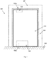
- FIG. 1 shows a door system 100 comprising a door leaf 101 which is hingeably mounted in a door frame 104 using a pivot door hinge 102 and a top hinge 103 using pivot axles 106a, 106b respectively.
- the axle 106a is fixedly mounted to a corresponding holder on the ground 105 or threshold or sill as the pivot axle 106b is fixedly mounted to the top 107 of the door frame 104.
- the top 107 can be a lintel for example.
- the door leaf 101 can swing around the rotation axles 106a, 106b is a single direction or preferably in both directions to and in figure 2 a torque versus angle diagram is shown of a pivot door hinge, wherein the torque is the torque exerted by the hinge mechanism relative to a rotation access of the pivot door hinge and the angle ⁇ is the angle of the rotation access relative to the pivot door hinge.
- Fig. 2 shows a desired torque versus angular position diagram for angle in a range from -110 ° to +110°. From the diagram it is clear that a high torque is required in angle positions around 0°, in order to provide a door wherein the pivot door hinge is mounted a stable position at this angle. For angles higher than 0° it is clear that the torque exerted on the rotation axle decreases with increasing angle.
- a diagram is shown showing desired braking resistance of the pivot door hinge in various angle zones A1, A2, D1, D2.
- the zones A1, A2 indicate braking action while closing the door moving from position 101b to position 101a and moving from position 101c to positions 101a.
- the zone A1 usually corresponds to all open positions, for example from over 90° to 0°. Thus, braking is to be provided over the entire range of open door positions while closing.
- the zone A2 indicates a zone having an optionally lower braking resistance than zone A1. This allows a door to assume its closed position more easily.
- braking is to be provided in the zone indicated with D1 while opening the door.
- zone D2 braking is provided additional to zone A1 while closing the door.
- FIG. 4 shows a cut away view of the pivot door hinge which is usually mounted at the lower part of the door.
- the pivot door hinge 102 comprises a housing 401, a closing mechanism 402 which comprises a closing spring 403, a displacement device for the closing mechanism 402 in the form of closing plunger 404, a closing cam 406 with camp follower 405.
- the pivot door hinge 102 further comprises a braking mechanism 407, which comprises a braking spring 408, another displacement device for the braking mechanism 407 in the form of a braking plunger 409, a braking cam 411 and corresponding cam wheel 410 acting as a cam follower connected to the braking plunger 409.
- the cam 406 for the closing mechanism 402 and the braking cam 411 for the braking mechanism 407 are mounted at mutually exchangeable positions of the rotation axle 106a.
- the closing mechanism 402 and braking mechanism 407 are mounted in respective cavities forming pressure chambers 412, 413 for the respective closing mechanism 402 and braking mechanism 407 within the pivot door hinge housing 401.
- the pivot axle 106a is accommodated in buffer chambers 414a, 414b, corresponding to the closing cam 406 and the braking cam 411 respectively.
- the buffer chambers 414a, 414b for the pivot axle 106a and the respective closing cam 406 and braking cam 411 may be fluidly interconnected.
- These buffer chambers 414a, 414b are designed to hold a hydraulic fluid which is displaced by the respective plungers 404, 409 of the closing mechanism 402 and braking mechanism 407.
- FIGS 5a, 5b show a closing mechanism 402 at different angles ⁇ of the closing cam 406 relative to a center line 502 of the closing mechanism 402.
- the closing mechanism 402 comprises the closing spring 403, the plunger 404 accommodated in the closing mechanism pressure chamber 412 of the housing 401, the closing cam 406 being mounted on the pivot axle 106a.
- the cam follower 405 which is shown as a cam wheel, rests against an indentation of a heart shaped closing cam 406.
- cam wheel 405 contacts the cam 406 at tangent 501a.
- the closing spring 403 exerts a force F spring a to the closing cam 406
- a force F a is exerted in a direction perpendicular to the tangent 501a, at an arm with length A a
- a torque T a is exerted on the cam 406. Since the cam wheel 405 also contacts the closing cam 406 at a point symmetrical of the center line 502 the total torque exerted however on the closing cam 406 is reduced to 0.
- the cam wheel 405 touches the closing cam 406 at tangent 501b.
- the closing cam 406 has rotated with an angle of ⁇ 1 relative to the centerline 502.
- the distance between the center of the closing cam 406 and the center of the cam wheel 405 has increased which gives rise to an increased force F spring b of closing spring 403 to the plunger 404.
- the force F b exerted by the cam wheel 405 to the closing cam 406 at arm length A b results in a torque T b exerted on the cam 406 and subsequently on the pivot axle 106b.
- the angle ⁇ 1 in fig. 5b corresponds to an angle ⁇ of closing cam center line 503 in an exemplary range between 45° and 110° as shown in figure 2 .
- the torque T b exerted on the closing cam 406 and subsequently the pivot axle 106a is less than the torque T a exerted in the lower angle ⁇ regions between 0° and 45°.
- Figures 6a - 6c show the braking mechanism 407 for different angles of the pivot axle 106a and corresponding angles of the braking cam 411.
- the distance D between cam wheel 410 center point to the rotation point of the braking cam 411 will vary depending on the rotation angle ⁇ relative to braking cam center line 605. This distance D determines the position of braking plunger 409 within pressure chamber 413.
- the braking plunger 409 displaces hydraulic liquid within the pressure chamber 413 to the cam buffer chamber 414b of fig. 4 .
- the flow of this hydraulic fluid and resistance provided in the path of the hydraulic fluid provides braking torque of the braking mechanism 407.
- the braking cam 411 is shown figures 6a - 6c symmetrically built relative to braking cam center line 605 to have the same profile for corresponding angles ⁇ >0° and angles ⁇ 0°, however the braking cam 411 may also be asymmetrical to have a different profile for angles ⁇ >0° and angles ⁇ 0°.
- the braking cam 411 has a protrusion 601 arranged to push cam wheel 410 away from the pivot axle center (indicated as a black dot within the braking cam 411 at low angles ⁇ corresponding to a closed-door position.
- the braking cam 411 has another protrusion 603 arranged to push cam wheel 410 away from the pivot axle center at angles ⁇ corresponding to an open-door position.
- the cam wheel 410 touches the braking cam 411 at protrusion 601.
- the distance D will decrease and become less than d1.
- the distance D will increase and become more than d1.
- the cam wheel 410 center point will increase the distance D from the rotation point of the braking cam 411 to enable additional braking torque on top of the braking of the closing mechanism 402.
- the cam wheel 410 center point will also increase its distance D from the rotation point of the braking cam 411 to enable additional braking action on top of the braking of the closing mechanism 402.
- the cam wheel 410 touches the braking cam 411 at protrusion 603.
- Distance D d3 which corresponds to another braking resistance value in this position, (i.e. d3>d2).
- the braking spring 408 of the braking mechanism 407 may have a spring constant which is sufficient to keep the cam wheel 410 in touch with the braking cam 411.
- the closing spring 403 however must be dimensioned with a spring constant sufficiently high enough to provide closing torque when de door is in an open position.
- the ratio between braking constant and closing constant can be 1 to at least 5.
- the ratio can be 1 to at least 15, more preferably the ratio can be 1 to at least 25.
- Fig. 7 shows an optional hydraulic circuit 713 for the closing mechanism 402 and a hydraulic circuit 708 for the braking mechanism 407.
- the closing cam 406 of the closing mechanism 402 and braking cam 411 of the braking mechanism 407 respectively are shown in top view respectively and being schematically interconnected by pivot axle 106a with a dashed double line. Normally the cams 406, 411 are attached to the pivot axle 106a in a spaced manner.
- the plunger 404 is actuated by the cam wheel 405 and closing cam 406 in accordance with figures 6a - 6c .
- the circuit 713 further comprises one-way valve 701 which is arranged in a hydraulic fluid channel 702 through the plunger 404. Parallel to the hydraulic fluid channel 702 a path comprising channels 717, 716 is arranged within the housing 401 which comprises a variable hydraulic resistance 705. Furthermore, the circuit comprises a bypass 707 and hydraulic resistance 706 included in series in hydraulic fluid channel 715 - 722.
- bypass 707 may direct the hydraulic fluid through hydraulic fluid channel 722 and hydraulic resistance 706 to hydraulic fluid channel 715, thereby creating a lower resistance and corresponding lower braking torque for these angles. This allows the door to move from an open position to a completely closed position. Braking torque is proportional to the angular door speed and proportional to the fluid resistance value of hydraulic resistance 706.
- the hydraulic circuit 708 for the braking mechanism 407 comprises the pressure chamber 413 in which the braking plunger 409 and braking spring 408 are arranged.
- the buffer chamber 414b is the buffer chamber for the hydraulic fluid of the hydraulic circuit 708 for the braking mechanism 407.
- the braking plunger 409 is actuated by the cam wheel 410 and braking cam 411.
- the hydraulic circuit 708 comprises one-way valve 703 which is arranged in a hydraulic fluid channel 704 through the braking plunger 409. Parallel to the hydraulic fluid channel 704 a hydraulic fluid channel 720 is arranged within the housing 401 which comprises a variable hydraulic resistance 710.
- the hydraulic circuit 708 comprises a path comprising hydraulic fluid channels 714, 718 having a pressure relief valve 721. For pressures above a threshold value, for example 30 Bar, the pressure relief valve 721 will open to prevent damage to the hydraulic circuit 708 and the mechanical components, i.e. the pressure chamber 413.
- the one-way valve 703 is opened and the hydraulic fluid flows through one-way valve 703 with relatively low resistance or braking torque.
- the one-way valve 703 In the reverse direction while closing the door in this zone D1 of fig.3 , the one-way valve 703 is opened and the hydraulic fluid flows through one-way valve 703 with relatively low resistance or braking torque.
- the door having the door hinge 102 is thus protected against uncontrolled swinging open through its open position at or around 90°.
- Fig. 8 shows across section view of the closing mechanism 402 and braking mechanism 407.
- the one-way valve 701 of the closing mechanism is shown arranged within the closing plunger 404, having its blocking opening facing the closing cam 406 which is arranged in buffer chamber 414a, and it's through opening facing hydraulic fluid channel 702.
- the one-way valve 701 and hydraulic fluid channel 702 may alternatively be arranged in the housing 401.
- the bypass 707 of the closing mechanism hydraulic circuit 713 may be formed as a slit in the closing plunger 404.
- the one-way valve 703 of the braking mechanism 407 is shown arranged within the braking plunger 409, having its blocking side facing the braking cam 411 which is arranged in buffer chamber 414b, and it's through opening facing hydraulic fluid channel 704.
- the one-way valve 703 and hydraulic fluid channel 704 may alternatively also be arranged within the housing 401.
- the wording fluid channel may involve one or more fluid channel segments arranged in series optionally including a fluid resistance or valve.
- a fluid channel or channel segment may be a duct or a hidden channel bored or cast into the hinge housing.
- Pistons and plungers can be categorized as positive displacement devices.
Claims (10)
- Charnière de porte pivotante (102) comprenant :- un logement de charnière (401) pour le montage de la charnière de porte pivotante (102) sur une porte (101) ;- un axe de pivotement (106a) supporté de façon pivotante à l'intérieur du logement, l'axe de pivotement (106a) présentant une extrémité conçue pour ancrer de façon pivotante l'axe de pivotement (106a) sur une structure maintenant la porte,- un mécanisme de fermeture (402) disposé à l'intérieur du logement de charnière (401), le mécanisme de fermeture (402) étant relié de façon coopérative à l'axe de pivotement (106a), le mécanisme de fermeture (402) étant conçu pour fournir un couple de fermeture à l'axe de pivotement (106a), en fonction d'un profil de couple de position angulaire ; dans laquelle le mécanisme de fermeture (402) comprend :- une came de fermeture (406) reliée à l'axe de pivotement (106a) et disposée dans une première chambre tampon (414a) du logement de charnière (401), la came de fermeture (406) présentant un profil de came de fermeture correspondant au profil de couple de position angulaire ; et- un élément suiveur de came de fermeture (405), l'élément suiveur de came de fermeture (405) étant disposé de manière à toucher la came de fermeture (406) afin d'appliquer le couple de fermeture à l'axe de pivotement (106a) via la came de fermeture (406) ;- un premier dispositif de déplacement (404) relié à l'élément suiveur de came de fermeture (405), le premier dispositif de déplacement (404) étant disposé dans une première chambre de pression (412) du logement de charnière (401) ;- un premier élément à ressort (403) disposé dans la première chambre de pression (412) du logement de charnière (401), pour appliquer une première force de ressort au premier dispositif de déplacement (404) ;- dans laquelle le premier dispositif de déplacement (404) est conçu pour déplacer un fluide hydraulique entre la première chambre de pression (412) et la première chambre tampon (414a) ;- un mécanisme de freinage (407) disposé dans le logement de charnière (401), relié de façon coopérative à l'axe de pivotement (106a), le mécanisme de freinage (407) étant conçu pour fournir un couple de freinage permettant de contrôler l'un au moins parmi un mouvement de fermeture et un mouvement d'ouverture de la porte, le mécanisme de freinage comprenant :caractérisée en ce que- une came de freinage (411) reliée à l'axe de pivotement (106a) et disposée dans une deuxième chambre tampon (414b) du logement de charnière (401), la came de freinage (411) présentant un profil de came de freinage, le profil de came de freinage étant différent du profil de came de fermeture ; et- un élément suiveur de came de freinage (410) disposé de manière à toucher la came de freinage (411) afin d'appliquer le couple de freinage supplémentaire à l'axe de pivotement (106a) via la came de freinage (411) ;- un deuxième dispositif de déplacement (409) relié à l'élément suiveur de came de freinage (410), le deuxième dispositif de déplacement (409) étant disposé dans une deuxième chambre de pression (413) du logement de charnière (401) ;- un deuxième élément à ressort (408) disposé dans la deuxième chambre de pression (413) du logement de charnière (401), permettant d'appliquer une deuxième force de ressort au deuxième dispositif de déplacement (409) ;- un circuit hydraulique (708) disposé fonctionnellement entre la deuxième chambre tampon (414b) et la deuxième chambre de pression (413) ;- dans laquelle le deuxième dispositif de déplacement (409) est conçu pour déplacer un fluide hydraulique entre la deuxième chambre de pression (413) et la deuxième chambre tampon (414b) via l'une au moins parmi une résistance hydraulique (710) et une soupape unidirectionnelle (703) ; et- la came de freinage (411) présente un profil de freinage comprenant une première saillie (603) à un angle correspondant à une position de porte ouverte ;- dans laquelle la soupape unidirectionnelle (703) est conçue pour permettre à un fluide hydraulique de s'écouler à travers la soupape unidirectionnelle (703), de la deuxième chambre tampon (414b) vers la deuxième chambre de pression (413) pendant le fonctionnement, le deuxième dispositif de déplacement (409) se déplaçant vers l'axe de pivotement (106a) ; et- dans laquelle la deuxième soupape unidirectionnelle (703) est en outre conçue pour bloquer le fluide hydraulique pendant le fonctionnement, le deuxième dispositif de déplacement (404) s'éloignant de l'axe de pivotement (106a) pour permettre au fluide hydraulique de s'écouler de la chambre de pression (413) vers la deuxième chambre tampon (414b) via de la résistance hydraulique (710).
- Charnière de porte pivotante (102) selon la revendication 1, dans laquelle le mécanisme de fermeture (402) comprend un premier circuit hydraulique (713) disposé fonctionnellement entre la première chambre tampon (414a) et la première chambre de pression (412), conçu pour amortir un mouvement de fermeture de la porte (101), et le mécanisme de freinage (407) comprend le deuxième circuit hydraulique (708) disposé fonctionnellement entre la deuxième chambre tampon (414b) et la deuxième chambre de pression (413).
- Charnière de porte pivotante (102) selon la revendication 1 ou 2, dans laquelle la came de freinage (411) présente un profil de freinage comprenant une deuxième saillie (601) à une position angulaire correspondant à une position de porte fermée (α=0°), et une indentation (602) à une position angulaire (α=α1) entre la première saillie (603) et la deuxième saillie (601) .
- Charnière de porte pivotante (102) selon la revendication 2 ou la revendication 3, dans laquelle le premier circuit hydraulique (708) comprend :- un premier canal de fluide (702) entre la première chambre de pression (412) et la première chambre tampon (414a) ; et- une première soupape unidirectionnelle (701) disposée dans le premier canal de fluide (702) ;- un deuxième canal de fluide (717, 716) entre la première chambre de pression (412) et la première chambre tampon (414a), disposé parallèlement au premier canal de fluide (702) ; et- une première résistance de fluide (705) disposé dans le deuxième canal de fluide (717, 716) ; dans laquelle- le premier canal de fluide (702) et la première soupape unidirectionnelle (701) sont disposés à travers le premier dispositif de déplacement (404) .
- Charnière de porte pivotante (102) selon l'une quelconque des revendications précédentes, dans laquelle- la came de fermeture (406) présente un rayon augmentant substantiellement avec des positions angulaires croissantes ; et- la première soupape unidirectionnelle (701) est conçue pour permettre à un fluide hydraulique de s'écouler de la première chambre de pression (412) vers la première chambre tampon (414a) pendant le fonctionnement, le premier dispositif de déplacement (404) s'éloignant alors de l'axe de pivotement (106a), et la première soupape unidirectionnelle (701) étant conçue pour bloquer l'écoulement de fluide hydraulique pendant le fonctionnement, le premier dispositif de déplacement (404) se déplaçant alors vers l'axe de pivotement (106a).
- Charnière de porte pivotante (102) selon l'une quelconque des revendications précédentes, dans laquelle le circuit hydraulique (708) comprend en outre- un troisième canal de fluide (704) entre la deuxième chambre de pression (413) et la deuxième chambre tampon (414b) ;- un quatrième canal de fluide (720, 711) disposé parallèlement au troisième canal de fluide (704) ; et- une deuxième résistance de fluide (710) disposée dans le quatrième canal de fluide (720, 711) ; dans laquelle- le troisième canal de fluide (704) et la deuxième soupape unidirectionnelle (703) sont disposés à travers le deuxième dispositif de déplacement (409) .
- Charnière de porte pivotante (102) selon la revendication 6, dans laquelle le circuit hydraulique (708) comprend en outre un cinquième canal de fluide (714, 718) parallèle au troisième canal de fluide (704) et le quatrième canal de fluide (720, 711), le cinquième canal de fluide (714, 718) comprenant une soupape de décharge (721).
- Charnière de porte pivotante (102) selon l'une quelconque des revendications précédentes, dans laquelle la position de porte fermée correspond à un angle de came dans une plage de -20 à +20 degrés par rapport à une ligne médiane (604) du mécanisme de freinage (407).
- Charnière de porte pivotante (102) selon l'une quelconque des revendications précédentes, dans laquelle la position de porte ouverte correspond à un angle d'ouverture dans une plage de plus ou moins 70 - 110 degrés par rapport à une ligne médiane du mécanisme de freinage (407).
- Charnière de porte pivotante (102) selon l'une quelconque des revendications précédentes, dans laquelle le mécanisme de freinage (407) et le mécanisme de fermeture (402) sont disposés dans le logement de charnière (401) sur un même côté latéral de l'axe de pivotement (106a).
Applications Claiming Priority (2)
| Application Number | Priority Date | Filing Date | Title |
|---|---|---|---|
| EP17176622 | 2017-06-19 | ||
| PCT/EP2018/066275 WO2018234313A1 (fr) | 2017-06-19 | 2018-06-19 | Charnière de porte pivotante |
Publications (2)
| Publication Number | Publication Date |
|---|---|
| EP3642437A1 EP3642437A1 (fr) | 2020-04-29 |
| EP3642437B1 true EP3642437B1 (fr) | 2021-08-25 |
Family
ID=59077957
Family Applications (1)
| Application Number | Title | Priority Date | Filing Date |
|---|---|---|---|
| EP18730804.4A Active EP3642437B1 (fr) | 2017-06-19 | 2018-06-19 | Charnière de porte pivot |
Country Status (6)
| Country | Link |
|---|---|
| US (1) | US10961761B2 (fr) |
| EP (1) | EP3642437B1 (fr) |
| CN (1) | CN110914510B (fr) |
| AU (1) | AU2018286978B2 (fr) |
| ES (1) | ES2899652T3 (fr) |
| WO (1) | WO2018234313A1 (fr) |
Families Citing this family (6)
| Publication number | Priority date | Publication date | Assignee | Title |
|---|---|---|---|---|
| CA3105775C (fr) | 2018-07-06 | 2023-08-15 | Tim J. BOUNDY | Systemes et dispositifs de commande de fermeture de porte reglable |
| US11680434B1 (en) * | 2020-07-21 | 2023-06-20 | Andersen Corporation | Damped door closer system and method |
| US11841065B2 (en) | 2021-01-08 | 2023-12-12 | Moshun, LLC | Systems and devices for motion control |
| US20230088132A1 (en) | 2021-09-22 | 2023-03-23 | NewWave Medical, Inc. | Systems and methods for real-time image-based device localization |
| CN116066463A (zh) * | 2021-10-29 | 2023-05-05 | 北京小米移动软件有限公司 | 阻尼机构、铰链及折叠式电子设备 |
| WO2023156965A1 (fr) | 2022-02-18 | 2023-08-24 | Neuwave Medical, Inc. | Dispositifs de couplage et systèmes associés |
Family Cites Families (29)
| Publication number | Priority date | Publication date | Assignee | Title |
|---|---|---|---|---|
| US987467A (en) * | 1910-08-22 | 1911-03-21 | Oscar Katzenberger | Double-acting spring-hinge. |
| US2035823A (en) * | 1933-03-24 | 1936-03-31 | American Hardware Corp | Double acting spring hinge |
| US2603818A (en) * | 1948-04-12 | 1952-07-22 | George W Houlsby Jr | Door check mechanism |
| US2700175A (en) * | 1952-02-18 | 1955-01-25 | George W Houlsby Jr | Door closer mechanism |
| US2752627A (en) * | 1953-02-26 | 1956-07-03 | George W Houlsby Jr | Pivotal door check device |
| DE1409524A1 (de) * | 1959-09-05 | 1968-11-14 | Ver Baubeschlag Gretsch Co | Schliesser fuer Tueren |
| US3246362A (en) * | 1962-01-22 | 1966-04-19 | Jackson Exit Device Corp | Door closer |
| GB1174327A (en) * | 1966-09-24 | 1969-12-17 | Zd Y Umelecke Kovovyroby Narod | Improvements in or relating to Door Closers. |
| US4000540A (en) * | 1976-04-19 | 1977-01-04 | Lawrence Brothers Inc. | Spring loaded, adjustable walking door hinge |
| DE3345004A1 (de) * | 1983-12-13 | 1985-06-13 | Dorma-Baubeschlag Gmbh & Co Kg, 5828 Ennepetal | Obentuerschliesser |
| JPS62177880U (fr) * | 1986-04-30 | 1987-11-11 | ||
| GB8616922D0 (en) * | 1986-07-11 | 1986-08-20 | Chubb Lips Nederland Bv | Automatic door closer |
| GB2261914B (en) * | 1991-11-28 | 1995-08-30 | Jebron Ltd | Damper and method of controlling a door |
| DE10031403C2 (de) * | 2000-07-04 | 2002-05-23 | Dorma Gmbh & Co Kg | Obentürschließer mit einer Gleitschienenanordnung |
| KR200324642Y1 (ko) * | 2003-06-03 | 2003-08-25 | 박형태 | 플로어 힌지 |
| DE102004002625B4 (de) * | 2004-01-16 | 2012-10-18 | Dorma Gmbh + Co. Kg | Türschließer |
| US7007341B2 (en) * | 2004-02-13 | 2006-03-07 | Fu Luong Hi-Tech Co., Ltd. | Door closer |
| KR100586262B1 (ko) | 2004-08-24 | 2006-06-07 | 주식회사 아이원이노텍 | 대형도어용 자동복귀 힌지장치 |
| DE102007002651B4 (de) * | 2007-01-12 | 2015-04-30 | Dorma Deutschland Gmbh | Türschließer |
| KR100838189B1 (ko) * | 2007-09-17 | 2008-06-16 | 오세진 | 비매설 형태로 된 도어용 유압식 힌지장치 |
| GB2479145A (en) * | 2010-03-29 | 2011-10-05 | Ingersoll Rand Security Technologies Ltd | Door closer having two springs |
| PT2746508T (pt) * | 2010-09-06 | 2018-11-28 | In & Tec Srl | Dobradiça de fecho de portas, particularmente, para portas de vidro |
| CN102454326B (zh) * | 2010-10-14 | 2016-03-30 | 邹忠 | 带有自动定心组件的铰链 |
| US9099214B2 (en) * | 2011-04-19 | 2015-08-04 | King Abdulaziz City For Science And Technology | Controlling microparticles through a light field having controllable intensity and periodicity of maxima thereof |
| DE102013100293A1 (de) * | 2013-01-11 | 2014-07-17 | Eco Schulte Gmbh & Co. Kg | Türschließerantrieb |
| WO2015111027A1 (fr) | 2014-01-27 | 2015-07-30 | In & Tec S.R.L. | Charnière hydraulique à faible encombrement |
| CN204357252U (zh) | 2014-11-19 | 2015-05-27 | 湖州德冠门控有限公司 | 一种力可调式多段定位地弹簧 |
| CN204627257U (zh) | 2015-02-06 | 2015-09-09 | 刘伟平 | 一种双簧式液压地弹簧 |
| DE102015109315A1 (de) * | 2015-06-11 | 2016-12-15 | Dorma Deutschland Gmbh | Türbeschlag |
-
2018
- 2018-06-19 ES ES18730804T patent/ES2899652T3/es active Active
- 2018-06-19 WO PCT/EP2018/066275 patent/WO2018234313A1/fr active Search and Examination
- 2018-06-19 US US16/624,352 patent/US10961761B2/en active Active
- 2018-06-19 EP EP18730804.4A patent/EP3642437B1/fr active Active
- 2018-06-19 AU AU2018286978A patent/AU2018286978B2/en active Active
- 2018-06-19 CN CN201880046777.8A patent/CN110914510B/zh active Active
Also Published As
| Publication number | Publication date |
|---|---|
| AU2018286978A1 (en) | 2020-02-06 |
| EP3642437A1 (fr) | 2020-04-29 |
| CN110914510B (zh) | 2020-11-03 |
| AU2018286978B2 (en) | 2020-03-05 |
| CN110914510A (zh) | 2020-03-24 |
| WO2018234313A1 (fr) | 2018-12-27 |
| US20200408019A1 (en) | 2020-12-31 |
| ES2899652T3 (es) | 2022-03-14 |
| US10961761B2 (en) | 2021-03-30 |
Similar Documents
| Publication | Publication Date | Title |
|---|---|---|
| EP3642437B1 (fr) | Charnière de porte pivot | |
| US11268312B2 (en) | Combined door hinge with variable hydraulic damping and stopper device performance | |
| US8443487B2 (en) | Door closer with a braking mechanism | |
| US4349939A (en) | Automatic door closer | |
| US6886217B2 (en) | Door closer | |
| CA2942161C (fr) | Charniere hydraulique, en particulier charniere dissimulee pour portes | |
| US20150218863A1 (en) | Low profile adjustable soft close hinge apparatus | |
| US20180238092A1 (en) | Combined Door Hinge with Variable Hydraulic Damping and Stopper Device Performance | |
| US20130081227A1 (en) | Door closer | |
| KR20150029604A (ko) | 가구용 감속 힌지 | |
| TWM516638U (zh) | 阻尼鉸鏈 | |
| CA2925684A1 (fr) | Dispositif de charniere pour portes, volets ou analogues | |
| GB2541716A (en) | Damped hinge | |
| CN109415921B (zh) | 铰接机构和铰接组件 | |
| AU2021286301A1 (en) | A hinge | |
| CN110965886A (zh) | 可调式闭门器 | |
| GB2433296A (en) | Door operator comprising resilient actuator and damping means operated by separate cams | |
| KR20230111721A (ko) | 댐핑 조절 볼트의 이탈 방지가 가능한 플로어 힌지장치 |
Legal Events
| Date | Code | Title | Description |
|---|---|---|---|
| STAA | Information on the status of an ep patent application or granted ep patent |
Free format text: STATUS: UNKNOWN |
|
| STAA | Information on the status of an ep patent application or granted ep patent |
Free format text: STATUS: THE INTERNATIONAL PUBLICATION HAS BEEN MADE |
|
| PUAI | Public reference made under article 153(3) epc to a published international application that has entered the european phase |
Free format text: ORIGINAL CODE: 0009012 |
|
| STAA | Information on the status of an ep patent application or granted ep patent |
Free format text: STATUS: REQUEST FOR EXAMINATION WAS MADE |
|
| 17P | Request for examination filed |
Effective date: 20200115 |
|
| AK | Designated contracting states |
Kind code of ref document: A1 Designated state(s): AL AT BE BG CH CY CZ DE DK EE ES FI FR GB GR HR HU IE IS IT LI LT LU LV MC MK MT NL NO PL PT RO RS SE SI SK SM TR |
|
| AX | Request for extension of the european patent |
Extension state: BA ME |
|
| DAV | Request for validation of the european patent (deleted) | ||
| DAX | Request for extension of the european patent (deleted) | ||
| GRAP | Despatch of communication of intention to grant a patent |
Free format text: ORIGINAL CODE: EPIDOSNIGR1 |
|
| STAA | Information on the status of an ep patent application or granted ep patent |
Free format text: STATUS: GRANT OF PATENT IS INTENDED |
|
| INTG | Intention to grant announced |
Effective date: 20210317 |
|
| GRAS | Grant fee paid |
Free format text: ORIGINAL CODE: EPIDOSNIGR3 |
|
| GRAA | (expected) grant |
Free format text: ORIGINAL CODE: 0009210 |
|
| STAA | Information on the status of an ep patent application or granted ep patent |
Free format text: STATUS: THE PATENT HAS BEEN GRANTED |
|
| AK | Designated contracting states |
Kind code of ref document: B1 Designated state(s): AL AT BE BG CH CY CZ DE DK EE ES FI FR GB GR HR HU IE IS IT LI LT LU LV MC MK MT NL NO PL PT RO RS SE SI SK SM TR |
|
| REG | Reference to a national code |
Ref country code: CH Ref legal event code: EP |
|
| REG | Reference to a national code |
Ref country code: DE Ref legal event code: R096 Ref document number: 602018022402 Country of ref document: DE |
|
| REG | Reference to a national code |
Ref country code: IE Ref legal event code: FG4D Ref country code: AT Ref legal event code: REF Ref document number: 1423955 Country of ref document: AT Kind code of ref document: T Effective date: 20210915 |
|
| REG | Reference to a national code |
Ref country code: SE Ref legal event code: TRGR |
|
| REG | Reference to a national code |
Ref country code: LT Ref legal event code: MG9D |
|
| REG | Reference to a national code |
Ref country code: NL Ref legal event code: FP |
|
| REG | Reference to a national code |
Ref country code: AT Ref legal event code: MK05 Ref document number: 1423955 Country of ref document: AT Kind code of ref document: T Effective date: 20210825 |
|
| PG25 | Lapsed in a contracting state [announced via postgrant information from national office to epo] |
Ref country code: NO Free format text: LAPSE BECAUSE OF FAILURE TO SUBMIT A TRANSLATION OF THE DESCRIPTION OR TO PAY THE FEE WITHIN THE PRESCRIBED TIME-LIMIT Effective date: 20211125 Ref country code: PT Free format text: LAPSE BECAUSE OF FAILURE TO SUBMIT A TRANSLATION OF THE DESCRIPTION OR TO PAY THE FEE WITHIN THE PRESCRIBED TIME-LIMIT Effective date: 20211227 Ref country code: LT Free format text: LAPSE BECAUSE OF FAILURE TO SUBMIT A TRANSLATION OF THE DESCRIPTION OR TO PAY THE FEE WITHIN THE PRESCRIBED TIME-LIMIT Effective date: 20210825 Ref country code: BG Free format text: LAPSE BECAUSE OF FAILURE TO SUBMIT A TRANSLATION OF THE DESCRIPTION OR TO PAY THE FEE WITHIN THE PRESCRIBED TIME-LIMIT Effective date: 20211125 Ref country code: AT Free format text: LAPSE BECAUSE OF FAILURE TO SUBMIT A TRANSLATION OF THE DESCRIPTION OR TO PAY THE FEE WITHIN THE PRESCRIBED TIME-LIMIT Effective date: 20210825 Ref country code: RS Free format text: LAPSE BECAUSE OF FAILURE TO SUBMIT A TRANSLATION OF THE DESCRIPTION OR TO PAY THE FEE WITHIN THE PRESCRIBED TIME-LIMIT Effective date: 20210825 Ref country code: HR Free format text: LAPSE BECAUSE OF FAILURE TO SUBMIT A TRANSLATION OF THE DESCRIPTION OR TO PAY THE FEE WITHIN THE PRESCRIBED TIME-LIMIT Effective date: 20210825 Ref country code: FI Free format text: LAPSE BECAUSE OF FAILURE TO SUBMIT A TRANSLATION OF THE DESCRIPTION OR TO PAY THE FEE WITHIN THE PRESCRIBED TIME-LIMIT Effective date: 20210825 |
|
| PG25 | Lapsed in a contracting state [announced via postgrant information from national office to epo] |
Ref country code: PL Free format text: LAPSE BECAUSE OF FAILURE TO SUBMIT A TRANSLATION OF THE DESCRIPTION OR TO PAY THE FEE WITHIN THE PRESCRIBED TIME-LIMIT Effective date: 20210825 Ref country code: LV Free format text: LAPSE BECAUSE OF FAILURE TO SUBMIT A TRANSLATION OF THE DESCRIPTION OR TO PAY THE FEE WITHIN THE PRESCRIBED TIME-LIMIT Effective date: 20210825 Ref country code: GR Free format text: LAPSE BECAUSE OF FAILURE TO SUBMIT A TRANSLATION OF THE DESCRIPTION OR TO PAY THE FEE WITHIN THE PRESCRIBED TIME-LIMIT Effective date: 20211126 |
|
| REG | Reference to a national code |
Ref country code: ES Ref legal event code: FG2A Ref document number: 2899652 Country of ref document: ES Kind code of ref document: T3 Effective date: 20220314 |
|
| PG25 | Lapsed in a contracting state [announced via postgrant information from national office to epo] |
Ref country code: DK Free format text: LAPSE BECAUSE OF FAILURE TO SUBMIT A TRANSLATION OF THE DESCRIPTION OR TO PAY THE FEE WITHIN THE PRESCRIBED TIME-LIMIT Effective date: 20210825 |
|
| REG | Reference to a national code |
Ref country code: DE Ref legal event code: R097 Ref document number: 602018022402 Country of ref document: DE |
|
| PG25 | Lapsed in a contracting state [announced via postgrant information from national office to epo] |
Ref country code: SM Free format text: LAPSE BECAUSE OF FAILURE TO SUBMIT A TRANSLATION OF THE DESCRIPTION OR TO PAY THE FEE WITHIN THE PRESCRIBED TIME-LIMIT Effective date: 20210825 Ref country code: SK Free format text: LAPSE BECAUSE OF FAILURE TO SUBMIT A TRANSLATION OF THE DESCRIPTION OR TO PAY THE FEE WITHIN THE PRESCRIBED TIME-LIMIT Effective date: 20210825 Ref country code: RO Free format text: LAPSE BECAUSE OF FAILURE TO SUBMIT A TRANSLATION OF THE DESCRIPTION OR TO PAY THE FEE WITHIN THE PRESCRIBED TIME-LIMIT Effective date: 20210825 Ref country code: EE Free format text: LAPSE BECAUSE OF FAILURE TO SUBMIT A TRANSLATION OF THE DESCRIPTION OR TO PAY THE FEE WITHIN THE PRESCRIBED TIME-LIMIT Effective date: 20210825 Ref country code: CZ Free format text: LAPSE BECAUSE OF FAILURE TO SUBMIT A TRANSLATION OF THE DESCRIPTION OR TO PAY THE FEE WITHIN THE PRESCRIBED TIME-LIMIT Effective date: 20210825 Ref country code: AL Free format text: LAPSE BECAUSE OF FAILURE TO SUBMIT A TRANSLATION OF THE DESCRIPTION OR TO PAY THE FEE WITHIN THE PRESCRIBED TIME-LIMIT Effective date: 20210825 |
|
| PLBE | No opposition filed within time limit |
Free format text: ORIGINAL CODE: 0009261 |
|
| STAA | Information on the status of an ep patent application or granted ep patent |
Free format text: STATUS: NO OPPOSITION FILED WITHIN TIME LIMIT |
|
| 26N | No opposition filed |
Effective date: 20220527 |
|
| PG25 | Lapsed in a contracting state [announced via postgrant information from national office to epo] |
Ref country code: SI Free format text: LAPSE BECAUSE OF FAILURE TO SUBMIT A TRANSLATION OF THE DESCRIPTION OR TO PAY THE FEE WITHIN THE PRESCRIBED TIME-LIMIT Effective date: 20210825 |
|
| PG25 | Lapsed in a contracting state [announced via postgrant information from national office to epo] |
Ref country code: MC Free format text: LAPSE BECAUSE OF FAILURE TO SUBMIT A TRANSLATION OF THE DESCRIPTION OR TO PAY THE FEE WITHIN THE PRESCRIBED TIME-LIMIT Effective date: 20210825 |
|
| PG25 | Lapsed in a contracting state [announced via postgrant information from national office to epo] |
Ref country code: LU Free format text: LAPSE BECAUSE OF NON-PAYMENT OF DUE FEES Effective date: 20220619 |
|
| PGFP | Annual fee paid to national office [announced via postgrant information from national office to epo] |
Ref country code: NL Payment date: 20230515 Year of fee payment: 6 Ref country code: IT Payment date: 20230510 Year of fee payment: 6 Ref country code: IE Payment date: 20230510 Year of fee payment: 6 Ref country code: FR Payment date: 20230510 Year of fee payment: 6 Ref country code: DE Payment date: 20230502 Year of fee payment: 6 |
|
| PGFP | Annual fee paid to national office [announced via postgrant information from national office to epo] |
Ref country code: TR Payment date: 20230616 Year of fee payment: 6 Ref country code: SE Payment date: 20230510 Year of fee payment: 6 |
|
| PGFP | Annual fee paid to national office [announced via postgrant information from national office to epo] |
Ref country code: BE Payment date: 20230517 Year of fee payment: 6 |
|
| PGFP | Annual fee paid to national office [announced via postgrant information from national office to epo] |
Ref country code: GB Payment date: 20230504 Year of fee payment: 6 Ref country code: ES Payment date: 20230711 Year of fee payment: 6 Ref country code: CH Payment date: 20230702 Year of fee payment: 6 |
|
| PG25 | Lapsed in a contracting state [announced via postgrant information from national office to epo] |
Ref country code: MK Free format text: LAPSE BECAUSE OF FAILURE TO SUBMIT A TRANSLATION OF THE DESCRIPTION OR TO PAY THE FEE WITHIN THE PRESCRIBED TIME-LIMIT Effective date: 20210825 Ref country code: CY Free format text: LAPSE BECAUSE OF FAILURE TO SUBMIT A TRANSLATION OF THE DESCRIPTION OR TO PAY THE FEE WITHIN THE PRESCRIBED TIME-LIMIT Effective date: 20210825 |