EP3641971B1 - Doppelte trennscheibe mit gekrümmten verformungslinien - Google Patents
Doppelte trennscheibe mit gekrümmten verformungslinien Download PDFInfo
- Publication number
- EP3641971B1 EP3641971B1 EP18731487.7A EP18731487A EP3641971B1 EP 3641971 B1 EP3641971 B1 EP 3641971B1 EP 18731487 A EP18731487 A EP 18731487A EP 3641971 B1 EP3641971 B1 EP 3641971B1
- Authority
- EP
- European Patent Office
- Prior art keywords
- disc
- shaped elements
- cutting disc
- rotary cutting
- deformation
- Prior art date
- Legal status (The legal status is an assumption and is not a legal conclusion. Google has not performed a legal analysis and makes no representation as to the accuracy of the status listed.)
- Active
Links
Images




Classifications
-
- B—PERFORMING OPERATIONS; TRANSPORTING
- B23—MACHINE TOOLS; METAL-WORKING NOT OTHERWISE PROVIDED FOR
- B23D—PLANING; SLOTTING; SHEARING; BROACHING; SAWING; FILING; SCRAPING; LIKE OPERATIONS FOR WORKING METAL BY REMOVING MATERIAL, NOT OTHERWISE PROVIDED FOR
- B23D61/00—Tools for sawing machines or sawing devices; Clamping devices for these tools
- B23D61/02—Circular saw blades
- B23D61/025—Details of saw blade body
- B23D61/026—Composite body, e.g. laminated
-
- B—PERFORMING OPERATIONS; TRANSPORTING
- B26—HAND CUTTING TOOLS; CUTTING; SEVERING
- B26D—CUTTING; DETAILS COMMON TO MACHINES FOR PERFORATING, PUNCHING, CUTTING-OUT, STAMPING-OUT OR SEVERING
- B26D1/00—Cutting through work characterised by the nature or movement of the cutting member or particular materials not otherwise provided for; Apparatus or machines therefor; Cutting members therefor
- B26D1/0006—Cutting members therefor
-
- B—PERFORMING OPERATIONS; TRANSPORTING
- B26—HAND CUTTING TOOLS; CUTTING; SEVERING
- B26D—CUTTING; DETAILS COMMON TO MACHINES FOR PERFORATING, PUNCHING, CUTTING-OUT, STAMPING-OUT OR SEVERING
- B26D1/00—Cutting through work characterised by the nature or movement of the cutting member or particular materials not otherwise provided for; Apparatus or machines therefor; Cutting members therefor
- B26D1/0006—Cutting members therefor
- B26D2001/0033—Cutting members therefor assembled from multiple blades
-
- B—PERFORMING OPERATIONS; TRANSPORTING
- B26—HAND CUTTING TOOLS; CUTTING; SEVERING
- B26D—CUTTING; DETAILS COMMON TO MACHINES FOR PERFORATING, PUNCHING, CUTTING-OUT, STAMPING-OUT OR SEVERING
- B26D1/00—Cutting through work characterised by the nature or movement of the cutting member or particular materials not otherwise provided for; Apparatus or machines therefor; Cutting members therefor
- B26D1/0006—Cutting members therefor
- B26D2001/0046—Cutting members therefor rotating continuously about an axis perpendicular to the edge
-
- B—PERFORMING OPERATIONS; TRANSPORTING
- B26—HAND CUTTING TOOLS; CUTTING; SEVERING
- B26D—CUTTING; DETAILS COMMON TO MACHINES FOR PERFORATING, PUNCHING, CUTTING-OUT, STAMPING-OUT OR SEVERING
- B26D1/00—Cutting through work characterised by the nature or movement of the cutting member or particular materials not otherwise provided for; Apparatus or machines therefor; Cutting members therefor
- B26D1/0006—Cutting members therefor
- B26D2001/0053—Cutting members therefor having a special cutting edge section or blade section
Definitions
- the present invention is related to a cutting disc or diamond blade for cutting materials. More particularly, the present invention relates to a cutting disc with a novel configuration allowing for improved dynamical properties of the cutting disc in operation.
- Rotary cutting discs are widely employed in different fields of technology for cutting purposes. Cutting discs of relatively small dimensions in the submillimetric range are used for medical purposes, for example in the field of odontology. Cutting discs having diameters in a range from approximately 50 cm to as large as 2 m are used for instance in the fields of metallurgy, civil construction and wood processing for cutting a variety of materials.
- Rotating machinery as any dynamical system, is exposed to vibrations and deformations depending for instance upon structural properties thereof, possible functioning faults and force imbalances.
- a thin rotary cutting disc rotating in a physical environment may severely deform when subjected to loss of dynamical stability and to arising resonances. This may result in a widening and a deviation of the intended cutting line, such that the final cutting line may in some instances be several times wider than the width of the cutting disc, which leads to increased material consumption, reduced cutting precision, increased wear of the cutting disc and increased power consumption. Further, this undesired stability loss may lead to fatal mechanical disruptions of the cutting disc itself or the surrounding machinery as a result of increased forces transversal to the cutting line.
- the cutting disc may penetrate sideways into the material being cut along a direction perpendicular to the cutting line, which may cause severe damage to the cutting disc or cause the cutting disc to remain trapped and/or bent upon turning off the cutting machine.
- Cutting discs having a double-disc configuration comprising disjoint monolithic disc-shaped elements are known from JP Ho6 312314 A , CN 101 518 838 A , and from CN 201 471 006 U .
- JP H02 311260 A discloses a disc-shaped cutting blade comprising two disc-shaped elements.
- the two disc-shaped elements comprise wave grooves for cooling formed in a spiral shape therein.
- the disc-shaped elements are steel plates separated from each other by a viscoelastic resin layer throughout their surface.
- the steel plates are spot welded together by spot welding and are adhered to each other but instead of including cooling wave grooves include cooling holes arranged at equal radial distances from a centre of the disc-shaped cutting blade.
- JP H03 104608 A discloses a disc-shaped rotary substrate comprising two thin unit plates that are bent outwardly away from each other at a peripheral side to support a cutting tip.
- the dynamical stability of the cutting disc is governed by its vibrational modes. Namely, as any mechanical object with some degree of elasticity, the cutting disc will exhibit certain vibrational modes in which the cutting disc can exhibit standing wave deformation vibrations at corresponding mode frequencies. These modes are usually referred to as “resonances” in the art, and the corresponding frequency is referred to as the “resonance frequency” or, from a mathematical perspective, "eigenfrequency" of the disc.
- the mode frequencies are found to diverge with increasing rotational speed, and it is seen that at some rotation frequency, which corresponds to the "critical frequency” referred to in the introductory portion above, the resonance frequency of one of the "split modes" becomes zero.
- the aforementioned “critical frequency” indeed sets an upper limit for the rotational speed of the cutting blade in operation, and thereby an upper limit for the cutting efficiency.
- a vibrational mode is essentially a standing wave, which is in turn the result of the superposition of two counter directional waves.
- a standing wave can be generated by circumferential deformation waves propagating in clockwise and counter clockwise directions, respectively.
- the present inventor has carried out simulations of this full continuum mechanics problem regarding the deformation of the rotating disc and was able to determine the vibrational modes, as well as the corresponding frequencies, as a function of the rotational speed. With this insight into the dynamical behaviour of the continuum mechanics of the rotating disc, the inventor was able to establish a new design for a cutting disc, as set forth in claim 1 below, that permits increasing the critical frequency considerably as compared to discs of conventional design.
- a rotary cutting disc comprises two coaxial mutually opposed disc-shaped elements each having a circumferential edge, wherein circumferential edges of the disc-shaped elements are joined together forming a cutting edge of the cutting disc.
- the cutting disc is formed by the union of the two disc-shaped elements, wherein each disc-shaped element constitutes one half of the cutting disc.
- the circumferential edges of the disc-shaped elements are joined together forming a common circumferential edge that constitutes the cutting edge of the cutting disc, that is, the outermost edge of the cutting disc that is rotated against the material to be cut.
- the cutting edge may constitute the cutting surface of the cutting disc itself or may be used for accommodating any kind of cutting blades, teeth or the like on it.
- Each of the disc-shaped elements comprises one or more at least partly curved elongated deformation lines, wherein the one or more deformation lines have a radial distance from the centre of the cutting disc that increases along at least a part of the length of the deformation line.
- curved refers to the fact that the deformation lines do not extend straight along the radial direction of the disc-shaped elements only, but rather have a radial component and a component perpendicular thereto (i.e. angular or circumferential component).
- Partly curved refers to the fact that such curved shape may correspond to the entire length of a deformation line or only to a portion thereof.
- deformation lines increases along at least a part of the length of the deformation line implies that deformation lines according to this invention are not formed at a constant distance of the centre of the cutting disc, i.e. not ring-shaped. In terms of polar coordinates, the radial component of the deformation line would be dependent on the azimuthal phase.
- the deformation lines may for instance have a spiral form, a wavy form, any combination thereof, or any other partly curved form according to the above definition.
- the deformation lines may be formed as deformations of the material of which the disc-shaped elements are made. Typically, the deformation lines are formed by exerting a mechanical pressure upon the material from both sides of the disc-shaped elements of the cutting disc thereby causing a plastic deformation.
- the deformation lines may for example be formed by a rolling process.
- the term "line” shall not be understood literally, because the rolling lines will have a certain non-vanishing width, which however is much smaller than the length of the deformation line, such as at least 10 times smaller, typically at least 20 times smaller.
- the formation of the deformation lines causes so-called residual stresses to be present in the material, which has a relevant influence on the dynamical properties of the cutting disc.
- the inventor has realised that surprisingly the combination of the two-element design with the specific shape of the deformation lines causes an increase of the critical speed of the cutting disc in a synergistic manner, i.e. in a manner that exceeds by far the effect expected from each single design feature by itself.
- the increase in critical speed thanks to the cutting disc of the invention with respect to an analogous single-pieced cutting disc having the same diameter and total mass and having conventional annular deformation lines has been found to be of at least 33%, which results in a very significant increase in the cutting kinetical energy of more than 75%.
- the efficiency of a cutting operation with a cutting disc can be improved while maintaining acceptable levels of quality, cutting precision and safety.
- the dynamic behaviour of the cutting disc is governed by the rotational inertia tensor thereof.
- the rotational inertia tensor also known as angular mass tensor, of a system describes the rotational inertia of the system and the degree to which a rotation around one axis induces a rotation around another axes, as is typically known for precession phenomena.
- the off-diagonal terms are a measure of the "rotation rigidity" of a rotating system. The smaller an off-diagonal term J ⁇ is, the less resistance the system offers for a rotation around the direction ⁇ to induce a further rotation around the direction ⁇ , and hence the less stable the system is when rotating.
- the two disc-shaped elements are in contact with each other at their outermost circumferential edges, which jointly form the cutting edge of the cutting disc.
- the two disc-shaped elements form a cavity in between that contains a vacuum.
- the two disc-shaped elements are not continuously in contact with each other all along their respective radial length but instead are in contact with each other at their outermost circumferential edges, which jointly form the cutting edge of the cutting disc, and possibly in a neighbouring environment thereof, while they are mutually separated along the rest of their radial extensions corresponding to those portions of the disc-shaped elements that are not joined together forming the cutting edge of the cutting disc. An interspace between the two disc-shaped elements is then formed between these portions thereof which constitutes the cavity.
- the cutting edge of the cutting disc may be provided by a sealed junction or connection between the disc-shaped elements.
- the disc-shaped elements may be confined by an innermost circumferential edge around their common axis, which may for instance be formed around an opening suitable for accommodating a shaft.
- a sealed junction or connection may be provided between such an opening and the cavity between the disc-shaped elements, such that the cavity is a sealed cavity suitable for containing a vacuum.
- the two disc-shaped elements form a cavity in between that is filled with a fluid, preferably with a Newtonian or a non-Newtonian fluid such as a gas-like air, an inert gas or a combination thereof, or a liquid like water, an oil, a gel-like substance or a combination thereof that improves the dynamic behaviour of the disc.
- a fluid preferably with a Newtonian or a non-Newtonian fluid such as a gas-like air, an inert gas or a combination thereof, or a liquid like water, an oil, a gel-like substance or a combination thereof that improves the dynamic behaviour of the disc.
- the two disc-shaped elements form a cavity in between that is filled with a damping material, preferably with a damping material with viscoelastic properties such as rubber, silicate, a gel, a synthetic or natural material with vibration attenuating properties or a combination thereof.
- a damping material preferably with a damping material with viscoelastic properties such as rubber, silicate, a gel, a synthetic or natural material with vibration attenuating properties or a combination thereof.
- the presence of a vacuum, a fluid, or a damping material in the cavity may modify the dynamical properties of the cutting disc in an advantageous manner by increasing the damping behaviour and/or its mechanical resistance to uncontrolled deformations that may lead to deviations or irregularities of the cutting profile and contribute to the elevation of the critical rotational speed of the cutting disc.
- the disc-shaped elements are separated by a separating element.
- the separating element may contribute to a better static and dynamic stability of the cutting disc against deformations and vibrations.
- the separating element may be formed as an extension of the disc-shaped elements.
- the separating element may be an independent element.
- the separating element may be formed along an inner circumferential edge of the disc-shaped elements and around an opening confined by said inner circumferential edge for receiving a shaft.
- the separating element and/or the disc-shaped elements may be configured such that the disc-shaped elements assume a lens-shaped geometry, wherein the distance between the disc-shaped elements increases at least in part along the radial direction from the cutting edge towards the centre of the cutting disc.
- the distance between the disc-shaped elements may increase throughout their respective radial lengths or in a part thereof.
- the disc-shaped elements may assume the lens-shaped geometry in combination, such that the geometry of the rotary cutting disc is lens-shaped in the aforesaid sense. This may be achieved by appropriately choosing the dimensions and material composition of the separating element and/or by appropriately choosing the dimensions and/or the material composition of the disc-shaped elements.
- the lens-shaped geometry induced by the separating element and/or by the disc-shaped elements may further contribute to the aforementioned non-linear regime of the deformation behaviour of the cutting disc and hence to the increase of the critical frequency of the cutting disc.
- the separating element may be made of a monolithic material, for example a metal, or a composite material, and may have a width along the axial direction, i.e. an extension between the disc-shaped elements, of between R/1000 and 2R/3, preferably between R/100 and R/2, more preferably between R/10 and R/3, where R is the radius of the disc-shaped elements.
- the disc-shaped elements are made of a monolithic material, for example a metal, or a composite material.
- the distance between the disc-shaped elements may increase along the radial direction from the cutting edge towards the center of the cutting disc, throughout their respective radial lengths or in a part thereof, linearly, logarithmically, exponentially, and/or according to a polynomial function, a trigonometric function and/or a rational function.
- the one or more deformation lines formed on different disc-shaped elements are arranged in an overlaying configuration in the assembled state of the cutting disc. This means that the deformation lines as formed on the individual disc-shaped elements are mirror images of one another.
- the pattern of deformation lines on the individual disc-shaped elements are mirror images of one another, such that they could be arranged in an overlaying configuration in the assembled state of the rotary cutting disc, but are offset with respect to each other by a predefined angle.
- the offset of the deformation lines may lead to an increased degree of asymmetry of the cutting disc, which may further contribute to influence the deformation behaviour of the cutting disc in such a way as to increase the critical frequency of the cutting disc, as explained above.
- the pattern of deformation lines as formed on the individual disc-shaped elements is identical. This means that in the assembled state, where the individual disc-shaped elements are arranged back-to-back, the location and shape of the deformation lines are mirror images of each other.
- the one or more deformation lines are formed on an outer surface of the disc-shaped element not facing the opposed disc-shaped element.
- the radial distance of the one or more deformation lines increases monotonically along the length of the deformation line.
- the radial distance refers herein to the radial coordinate that would be used for describing the path of a deformation line on a disc-shaped element in polar coordinates, which would increase monotonically with increasing angle, i.e. along the length of the deformation line.
- This characteristic may extend to an entire deformation line or only to a portion thereof.
- the monotonic increase may for instance correspond to a linear increase or to a logarithmic increase, although other increase rates are possible as well.
- the deformation lines extend from a first end to a second end, said first end being located at the innermost circumferential edge of the disc-shaped elements, or within a distance of said innermost edge that is less than 15%, preferably less than 10% of the diameter of the respective disc-shaped element.
- the disc-shaped elements may be confined on one side by an innermost circumferential edge around their common axis, which may for instance be formed around an opening suitable for accommodating a shaft.
- the second end of the deformation lines is located at the cutting edge, or within a distance from said cutting edge that is less than 15%, preferably less than 10% of the diameter of the respective disc-shaped element.
- the two disc-shaped elements are welded or glued together.
- the disc-shaped elements may be welded together by means of point welding, line welding, friction welding, soldering, or glued together using a gluing paste.
- each of the disc-shaped elements comprises at least 4 deformation lines, preferably between 6 and 20 deformation lines.
- the deformation lines when expressed in polar coordinates, cover an angular range between 1° and 720°, preferably between 10° and 90°, along their length.
- the deformation lines preferably have the shape of a section of a circle having a centre located at a radial distance from the centre of the rotary cutting disc corresponding to 35% to 65%, preferably 40% to 60% and most preferably 45% to 55% of the radius of the rotary cutting disc.
- Fig. 1 shows a side view of a rotary cutting disc 10 according to an embodiment of the invention, which comprises two coaxial mutually opposed disc-shaped elements 12a and 12b.
- the disc-shaped elements 12a and 12b have a respective circumferential edge 14a and 14b.
- the circumferential edges 14a and 14b of the disc-shaped elements 12a and 12b are joined together forming a cutting edge 16 of the cutting disc 10.
- the disc-shaped elements 12a, 12b extend between a respective innermost circumferential edge 18a, 18b of the disc-shaped elements 12a, 12b and the respective outermost circumferential edge 14a, 14b.
- the innermost circumferential edges 18a, 18b are arranged around their common centre 20, and form an opening 26 suitable for receiving a driving shaft.
- the disc-shaped elements 12a and 12b are separated in a vicinity of their innermost circumferential edges 18a, 18b by a separating element 22.
- the circumferential disc-shaped elements 12a and 12b are tightly joined together at the cutting edge 16 and tightly joined to the separating element 22 and the outer walls of the opening 26, thereby forming a sealed cavity 24 between the disc-shaped elements 12a and 12b.
- the cavity 24 contains a vacuum.
- the separating element 22 and the disc-shaped elements are configured such that the disc-shaped elements 12a and 12b assume in combination a lens-shaped geometry, wherein the distance between the disc-shaped elements 12a and 12b increases along the radial direction from the cutting edge 16 towards the common centre 20, according to a tangent function.
- the separating element 22 is made of a monolithic metal and has a width of R/5, R being the radius of the disc-shaped elements 12a and 12b.
- the disc-shaped elements 12a and 12b are made of a metal.
- Fig. 2 shows a front side of the rotary cutting disc 10 of Fig. 1 .
- the disc-shaped elements 12a and 12b each comprise five curved elongated deformation lines 30 that have a radial distance to the centre 20 of the cutting disc 10 that increases monotonically along the length of the deformation line 30.
- the deformation lines 30 of the embodiment shown are "spiral-shaped", which however shall not be construed in a strict mathematical sense.
- the deformation lines 30 have the shape of a section of a circle having a centre located at a radial distance from the centre 20 of the disc-shaped element corresponding to half the radius R of the disc-shaped element.
- this shape is regarded as a "spiral-shaped" in the meaning of the present disclosure. According to this shape, when expressing the shape of the deformation line 30 in polar coordinates, this means that the angle coordinate changes monotonically along the length of the deformation line 30, and thereby covers an angular range of approximately 80°.
- the deformation lines 30 extend between an intermediate circumferential limit 32 and the cutting edge 16, wherein the intermediate circumferential limit 32 encloses the centre of the cutting disc 10 and has a radius greater than the radius 18 of the innermost circumferential edges 18a, 18b of the disc-shaped elements 12a and 12b.
- the deformation lines 30 have a width of 5.4 mm.
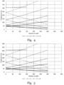
- Fig. 4 shows the six lowest resonance frequencies as a function of rotational speed determined from computer simulation for a reference prior art disc consisting of a monolithic cutting disc that is not made up from two coaxial mutually opposed disc-shaped elements, and comprising two annular deformation lines.
- a reference prior art disc 10' is shown in Fig. 3 , where elements of the disc 10' are indicated by the same reference numerals previously used for Fig. 1 and 2 , wherein it is understood that those elements previously referring to the disc-shaped elements refer in Fig. 3 to the monolithic cutting disc itself .
- the cutting disc 10' comprises two concentric annular deformation lines 30'.
- the first, third, fourth and fifth lowest resonance frequencies for the cutting disc 10 when at rest bifurcate and diverge with increasing rotational speed are not bifurcate, as they involve standing waves propagating counter directionally in circumferential direction.
- the second and sixth lowest resonance frequency do not bifurcate, as they involve standing waves propagating in radial direction only, which are not directly affected by the rotation.
- the respective curves are approximately horizontal, indicating that the resonance frequency is indeed largely unaffected by the increase in rotational speed.
- a closer look reveals that the curves are not perfectly horizontal, but slightly increase with rotational speed. This is due to the fact that the centripetal force acting on the cutting disc upon rotation leads to a stiffening of the disc, and hence a higher resonance frequency.
- the aim is to push the critical frequency, i.e. the lowest rotational speed at which one of the resonance frequencies drops to zero, to higher values.
- Fig. 5 shows the results of similar simulations as shown in Fig. 4 , again for a monolithic cutting disc, but having 5 spiral-shaped deformation lines instead of the two annular deformation lines analogous to the pattern of deformation lines 30 shown in Fig. 2 .
- the critical rotational frequency remains at 300 rad/s and is hence not improved.
- Fig. 6 shows the results of similar simulations as shown in Fig. 4 , but for a cutting disc comprising two disc-shaped elements separated by a separating element and having no deformation lines.
- the total mass of the two-part cutting disc is the same as that of the monolithic reference cutting disc of figures 3 and 5 .
- this configuration displays an increase in the critical frequency of about 17% with respect to the reference prior art model of Fig. 4 .
- Fig. 7 shows the results for a cutting disc analogous to that of Fig. 6 but comprising closed annular deformation lines around the centre of the cutting disc.
- the deformation lines on different disc-shaped elements are arrayed in an overlying configuration. No significant changes in the dynamical properties of the cutting disc as compared to that of Fig. 6 are observed which could be attributed to the closed annular deformation lines.
- Fig. 8 shows the results of computer simulations of the six lowest resonance frequencies as a function of rotational speed determined for a cutting disc according to an embodiment of the invention.
- This embodiment is analogous to that of Fig. 6 and 6 , but comprises curved - spiral - deformation lines analogous to those described with respect to Fig. 2 , wherein the deformation lines on different disc-shaped elements are arrayed in an overlying configuration.
- the combination of the two-part structure and the curved spiral deformation lines leads to an increase in the critical frequency of about 33% over the prior art design shown in Figs. 3 and 4 .
- the combined effect is hence much more than one would have expected from the individual effects of the two modifications over the disc of Figs. 3 and 4 .
- the cutting disc may be operated at a higher rotational speed without being disturbed by the effects of resonance, which allows higher work efficiency and safety.
Landscapes
- Engineering & Computer Science (AREA)
- Mechanical Engineering (AREA)
- Life Sciences & Earth Sciences (AREA)
- Forests & Forestry (AREA)
- Polishing Bodies And Polishing Tools (AREA)
- Sawing (AREA)
Claims (15)
- Rotierbare Trennscheibe (10), die Folgendes umfasst:zwei koaxiale, einander gegenüberliegende scheibenförmige Elemente (12a, 12b), die jeweils eine Umfangskante aufweisen, wobei Umfangskanten (14a, 14b) der scheibenförmigen Elemente (12a, 12b) aneinander liegen und eine Schneidkante (16) der Trennscheibe (10) bilden; wobei die scheibenförmigen Elemente (12a, 12b) aus einem monolithischen Material hergestellt sind undan ihren äußersten Umfangskanten, die gemeinsam die Schneidkante (16) bilden, miteinander in Kontakt stehen;wobei jedes der scheibenförmigen Elemente (12a, 12b) eine oder mehrere zumindest teilweise gekrümmte längliche Verformungslinien (30) aufweist,wobei die eine oder die mehreren Verformungslinien (30) einen radialen Abstand von der Mitte (26) der Trennscheibe (10) aufweisen, der entlang zumindest eines Teils der Länge der Verformungslinie (30) zunimmt.
- Rotierbare Trennscheibe (10) nach Anspruch 1, wobei die zwei scheibenförmigen Elemente (12a, 12b) einen Hohlraum (24) dazwischen bilden, der ein Vakuum enthält.
- Rotierbare Trennscheibe (10) nach Anspruch 1, wobei die zwei scheibenförmigen Elemente (12a, 12b) einen Hohlraum (24) dazwischen bilden, der mit einem Fluid gefüllt ist, vorzugsweise mit einem newtonschen oder einem nicht-newtonschen Fluid.
- Rotierbare Trennscheibe (10) nach Anspruch 1, wobei die zwei scheibenförmigen Elemente (12a, 12b) einen Hohlraum (24) dazwischen bilden, der mit einem Dämpfungsmaterial gefüllt ist, vorzugsweise mit einem Dämpfungsmaterial mit viskoelastischen Eigenschaften.
- Rotierbare Trennscheibe (10) nach einem der vorhergehenden Ansprüche, wobei die scheibenförmigen Elemente (12a, 12b) durch einen Abstandshalter (22) getrennt sind.
- Rotierbare Trennscheibe (10) nach einem der vorhergehenden Ansprüche, wobei der Abstandshalter (22) und/oder die scheibenförmigen Elemente (12a, 12b) so konfiguriert sind, dass die scheibenförmigen Elemente (12a, 12b) eine linsenförmige Geometrie annehmen, wobei der Abstand zwischen den scheibenförmigen Elementen (12a, 12b) zumindest teilweise entlang der radialen Richtung von der Schneidkante (16) zur Mitte (26) der Trennscheibe (10) zunimmt.
- Rotierbare Trennscheibe (10) nach einem der vorhergehenden Ansprüche, wobei die eine oder die mehreren Verformungslinien (30), die auf verschiedenen scheibenförmigen Elementen (12a, 12b) gebildet sind, in einer überlappenden Konfiguration angeordnet sind.
- Rotierbare Trennscheibe (10) nach Anspruch 7, wobei das Muster von Verformungslinien (30) auf den einzelnen scheibenförmigen Elementen (12a, 12b) Spiegelbilder voneinander sind, so dass sie im zusammengebauten Zustand der rotierbaren Trennscheibe (10) in einer überlappenden Konfiguration angeordnet sein könnten, aber um einen vordefinierten Winkel zueinander versetzt sind.
- Rotierbare Trennscheibe (10) nach einem der Ansprüche 1 bis 6, wobei das Muster von Verformungslinien (30), wie es auf den einzelnen scheibenförmigen Elementen (12a, 12b) gebildet ist, identisch ist.
- Rotierbare Trennscheibe (10) nach einem der vorhergehenden Ansprüche, wobei die eine oder die mehreren Verformungslinien (30) auf einer Außenfläche des scheibenförmigen Elements (12a, 12b) gebildet sind, die nicht dem gegenüberliegenden scheibenförmigen Element (12b, 12a) zugewandt ist.
- Rotierbare Trennscheibe (10) nach einem der vorhergehenden Ansprüche, wobei der radiale Abstand der einen oder der mehreren Verformungslinien (30) entlang der Länge der Verformungslinie (30) monoton zunimmt.
- Rotierbare Trennscheibe (10) nach einem der vorhergehenden Ansprüche, wobei sich die Verformungslinien (30) von einem ersten Ende zu einem zweiten Ende erstrecken, wobei das erste Ende an der innersten Kante (18a, 18b) der scheibenförmigen Elemente (12a, 12b) oder innerhalb eines Abstands von der innersten Kante (18a, 18b) angeordnet ist, der weniger als 15 %, vorzugsweise weniger als 10 % des Durchmessers des jeweiligen scheibenförmigen Elements (12a, 12b) beträgt.
- Rotierbare Trennscheibe (10) nach Anspruch 12, wobei das zweite Ende der Verformungslinien (30) an der Schneidkante (16) der Trennscheibe (10) oder innerhalb eines Abstands von der Schneidkante (16) angeordnet ist, der weniger als 15 %, vorzugsweise weniger als 10 % des Durchmessers des jeweiligen scheibenförmigen Elements (12a, 12b) beträgt.
- Rotierbare Trennscheibe (10) nach einem der vorhergehenden Ansprüche,wobei die zwei scheibenförmigen Elemente (12a, 12b) miteinander verschweißt oder verklebt sind; und/oderwobei jedes der scheibenförmigen Elemente (12a, 12b) mindestens 4 Verformungslinien (30), vorzugsweise zwischen 6 und 20 Verformungslinien (30), umfasst.
- Rotierbare Trennscheibe (10) nach einem der vorhergehenden Ansprüche, wobei die Verformungslinien (30), wenn sie in Polarkoordinaten ausgedrückt sind, einen Winkelbereich zwischen 1° und 720°, vorzugsweise zwischen 10° und 90°, entlang ihrer Länge abdecken, wobei der Wert der Winkelkoordinaten vorzugsweise entlang der Länge der Verformungslinie (30) monoton zunimmt oder abnimmt, und/oder wobei die Verformungslinien (30) vorzugsweise die Form eines Abschnitts eines Kreises mit einer Mitte aufweisen, die in einem radialen Abstand von der Mitte der rotierbaren Trennscheibe (10) angeordnet ist, der 35 % bis 65 %, vorzugsweise 40 % bis 60 % und am bevorzugtesten 45 % bis 55 % des Radius der rotierbaren Trennscheibe (10) entspricht.
Applications Claiming Priority (2)
| Application Number | Priority Date | Filing Date | Title |
|---|---|---|---|
| EP17177641.2A EP3417969A1 (de) | 2017-06-23 | 2017-06-23 | Doppelte trennscheibe mit gekrümmten verformungslinien |
| PCT/EP2018/066767 WO2018234547A1 (en) | 2017-06-23 | 2018-06-22 | Double cutting disc with curved deformation lines |
Publications (3)
| Publication Number | Publication Date |
|---|---|
| EP3641971A1 EP3641971A1 (de) | 2020-04-29 |
| EP3641971B1 true EP3641971B1 (de) | 2025-04-30 |
| EP3641971C0 EP3641971C0 (de) | 2025-04-30 |
Family
ID=59215600
Family Applications (2)
| Application Number | Title | Priority Date | Filing Date |
|---|---|---|---|
| EP17177641.2A Withdrawn EP3417969A1 (de) | 2017-06-23 | 2017-06-23 | Doppelte trennscheibe mit gekrümmten verformungslinien |
| EP18731487.7A Active EP3641971B1 (de) | 2017-06-23 | 2018-06-22 | Doppelte trennscheibe mit gekrümmten verformungslinien |
Family Applications Before (1)
| Application Number | Title | Priority Date | Filing Date |
|---|---|---|---|
| EP17177641.2A Withdrawn EP3417969A1 (de) | 2017-06-23 | 2017-06-23 | Doppelte trennscheibe mit gekrümmten verformungslinien |
Country Status (4)
| Country | Link |
|---|---|
| US (1) | US11623360B2 (de) |
| EP (2) | EP3417969A1 (de) |
| CN (1) | CN110730701B (de) |
| WO (1) | WO2018234547A1 (de) |
Families Citing this family (1)
| Publication number | Priority date | Publication date | Assignee | Title |
|---|---|---|---|---|
| CN116985223B (zh) * | 2023-09-27 | 2023-12-01 | 江苏鑫亿船舶装饰工程有限公司 | 一种用于家具板材加工的全自动锯断装置 |
Family Cites Families (18)
| Publication number | Priority date | Publication date | Assignee | Title |
|---|---|---|---|---|
| US4187754A (en) | 1978-09-21 | 1980-02-12 | Beaty Loma B | Noise dampened rotary saw blade |
| CN1006864B (zh) * | 1986-11-28 | 1990-02-21 | 莱贝弗公司 | 圆锯盘组合件 |
| JPH03104608A (ja) * | 1989-09-18 | 1991-05-01 | Efupure Kk | カッターブレード |
| JPH02311260A (ja) * | 1989-05-26 | 1990-12-26 | Sanki Kogyo Kk | 円板形切断刃 |
| JP2519166B2 (ja) * | 1993-04-26 | 1996-07-31 | ジャンプ工業株式会社 | カッタ―用基板 |
| JPH10180539A (ja) * | 1996-12-20 | 1998-07-07 | Matsushita Electric Works Ltd | 丸のこ刃 |
| DE50105224D1 (de) | 2000-02-29 | 2005-03-10 | Boehler Miller Messer Und Saeg | Stammblatt für Dünnschnitt-Kreissägen |
| DE10059978A1 (de) * | 2000-12-02 | 2002-06-06 | Bosch Gmbh Robert | Sägewerkzeug für eine Handkreissägemaschine |
| DE10059969A1 (de) * | 2000-12-02 | 2002-06-06 | Bosch Gmbh Robert | Sägewerkzeug für eine Handkreissägemaschine |
| SE524099C2 (sv) * | 2001-05-16 | 2004-06-29 | Nord Ct I Kalmar Ab | Sågklingepar |
| CN101116919A (zh) * | 2007-05-08 | 2008-02-06 | 郭一文 | 一种成对锯片 |
| DE102007022310A1 (de) * | 2007-05-12 | 2008-11-13 | Arno Friedrichs | Verfahren zur Herstellung eines Kühlkanäle aufweisenden Kreissägeblattes |
| CN101224513A (zh) * | 2008-01-25 | 2008-07-23 | 郭一文 | 具有防止锯片锁卡功能的成对锯片 |
| CN201471006U (zh) * | 2009-03-27 | 2010-05-19 | 厦门致力金刚石工具有限公司 | 消音锯片基体 |
| CN101518838B (zh) * | 2009-03-27 | 2012-06-13 | 厦门致力金刚石科技股份有限公司 | 一种消音锯片基体及其激光焊接方法 |
| CN202291660U (zh) * | 2011-10-31 | 2012-07-04 | 宁波黑松工具有限公司 | 双锯片切割机的锯片结构 |
| CN103143774B (zh) * | 2011-12-06 | 2016-08-03 | 博世电动工具(中国)有限公司 | 锯片 |
| EP2799176A1 (de) * | 2013-04-30 | 2014-11-05 | HILTI Aktiengesellschaft | Trennscheiben mit Sandwichbauweise |
-
2017
- 2017-06-23 EP EP17177641.2A patent/EP3417969A1/de not_active Withdrawn
-
2018
- 2018-06-22 WO PCT/EP2018/066767 patent/WO2018234547A1/en not_active Ceased
- 2018-06-22 EP EP18731487.7A patent/EP3641971B1/de active Active
- 2018-06-22 CN CN201880038682.1A patent/CN110730701B/zh active Active
- 2018-06-22 US US16/620,980 patent/US11623360B2/en active Active
Also Published As
| Publication number | Publication date |
|---|---|
| US20200108519A1 (en) | 2020-04-09 |
| CN110730701A (zh) | 2020-01-24 |
| CN110730701B (zh) | 2021-10-26 |
| EP3641971C0 (de) | 2025-04-30 |
| WO2018234547A1 (en) | 2018-12-27 |
| EP3641971A1 (de) | 2020-04-29 |
| US11623360B2 (en) | 2023-04-11 |
| EP3417969A1 (de) | 2018-12-26 |
Similar Documents
| Publication | Publication Date | Title |
|---|---|---|
| Presas et al. | Influence of the rotation on the natural frequencies of a submerged-confined disk in water | |
| Ahmadi et al. | Analytical stability lobes including nonlinear process damping effect on machining chatter | |
| US8529173B2 (en) | Method to align characteristic frequency of material removal tool and rotation speed of spindle of machine tool and material removal tool so aligned | |
| JPH04318232A (ja) | 分割ブラシシール及びその製造方法 | |
| US7059823B2 (en) | Molecular pump equipped with flange having buffering portion | |
| Xi et al. | A study on Q factor of the trimmed resonator for vibratory cupped gyroscopes | |
| US11623360B2 (en) | Double cutting disc with curved deformation lines | |
| Pardoen | Asymmetric vibration and stability of circular plates | |
| JP6791505B2 (ja) | 溝切り用ブレード | |
| Vinayak et al. | Eigensolutions of annular-like elastic disks with intentionally removed or added material | |
| Wang et al. | Axisymmetric dynamic stability of rotating sandwich circular plates | |
| Noga | Numerical and experimental analyses of vibrations of annular plates with multiple eccentric holes | |
| Soares et al. | Finite element dynamic analysis of practical discs | |
| JP3171791U (ja) | エンドミル | |
| Maretic et al. | Asymmetric vibrations and stability of a rotating annular plate loaded by a torque | |
| Kumar et al. | Simulation studies on combined effect of variable geometry, rotation and temperature gradient on critical speed of gas turbine disc | |
| Chonan et al. | Vibration and stability of rotating free-clamped slicing blades | |
| JP5954117B2 (ja) | 捩り振動減衰装置 | |
| Peng et al. | Research on coupling vibration of disk crack and shaft crack of rotor system based on finite element method | |
| Mao et al. | Out‐of‐Plane free vibration and forced harmonic response of a curved beam | |
| Kang | Dynamic instability of a spinning thick disk under nonconservative traction | |
| Bouboulas et al. | Vibration analysis of a rotating disk with a crack | |
| Renshaw | Maximizing the natural frequencies and transverse stiffness of centrally damped, circular disks by thickening the clamped part of the disk | |
| KR970706951A (ko) | 브로칭 공구(Broaching tool) | |
| EP1380376A1 (de) | Kreissäge und verfahren zur befestigung ihrer hauptspindel |
Legal Events
| Date | Code | Title | Description |
|---|---|---|---|
| STAA | Information on the status of an ep patent application or granted ep patent |
Free format text: STATUS: UNKNOWN |
|
| STAA | Information on the status of an ep patent application or granted ep patent |
Free format text: STATUS: THE INTERNATIONAL PUBLICATION HAS BEEN MADE |
|
| PUAI | Public reference made under article 153(3) epc to a published international application that has entered the european phase |
Free format text: ORIGINAL CODE: 0009012 |
|
| STAA | Information on the status of an ep patent application or granted ep patent |
Free format text: STATUS: REQUEST FOR EXAMINATION WAS MADE |
|
| 17P | Request for examination filed |
Effective date: 20191119 |
|
| AK | Designated contracting states |
Kind code of ref document: A1 Designated state(s): AL AT BE BG CH CY CZ DE DK EE ES FI FR GB GR HR HU IE IS IT LI LT LU LV MC MK MT NL NO PL PT RO RS SE SI SK SM TR |
|
| AX | Request for extension of the european patent |
Extension state: BA ME |
|
| DAV | Request for validation of the european patent (deleted) | ||
| DAX | Request for extension of the european patent (deleted) | ||
| STAA | Information on the status of an ep patent application or granted ep patent |
Free format text: STATUS: EXAMINATION IS IN PROGRESS |
|
| 17Q | First examination report despatched |
Effective date: 20220128 |
|
| GRAP | Despatch of communication of intention to grant a patent |
Free format text: ORIGINAL CODE: EPIDOSNIGR1 |
|
| STAA | Information on the status of an ep patent application or granted ep patent |
Free format text: STATUS: GRANT OF PATENT IS INTENDED |
|
| RIC1 | Information provided on ipc code assigned before grant |
Ipc: B26D 1/00 20060101ALI20240830BHEP Ipc: B23D 61/02 20060101AFI20240830BHEP |
|
| GRAJ | Information related to disapproval of communication of intention to grant by the applicant or resumption of examination proceedings by the epo deleted |
Free format text: ORIGINAL CODE: EPIDOSDIGR1 |
|
| INTG | Intention to grant announced |
Effective date: 20240916 |
|
| STAA | Information on the status of an ep patent application or granted ep patent |
Free format text: STATUS: EXAMINATION IS IN PROGRESS |
|
| INTC | Intention to grant announced (deleted) | ||
| GRAP | Despatch of communication of intention to grant a patent |
Free format text: ORIGINAL CODE: EPIDOSNIGR1 |
|
| STAA | Information on the status of an ep patent application or granted ep patent |
Free format text: STATUS: GRANT OF PATENT IS INTENDED |
|
| INTG | Intention to grant announced |
Effective date: 20241126 |
|
| RIN1 | Information on inventor provided before grant (corrected) |
Inventor name: MAEDER, MARCUS |
|
| GRAS | Grant fee paid |
Free format text: ORIGINAL CODE: EPIDOSNIGR3 |
|
| GRAA | (expected) grant |
Free format text: ORIGINAL CODE: 0009210 |
|
| STAA | Information on the status of an ep patent application or granted ep patent |
Free format text: STATUS: THE PATENT HAS BEEN GRANTED |
|
| AK | Designated contracting states |
Kind code of ref document: B1 Designated state(s): AL AT BE BG CH CY CZ DE DK EE ES FI FR GB GR HR HU IE IS IT LI LT LU LV MC MK MT NL NO PL PT RO RS SE SI SK SM TR |
|
| REG | Reference to a national code |
Ref country code: CH Ref legal event code: EP Ref country code: GB Ref legal event code: FG4D |
|
| REG | Reference to a national code |
Ref country code: IE Ref legal event code: FG4D |
|
| U01 | Request for unitary effect filed |
Effective date: 20250506 |
|
| U07 | Unitary effect registered |
Designated state(s): AT BE BG DE DK EE FI FR IT LT LU LV MT NL PT RO SE SI Effective date: 20250512 |
|
| U20 | Renewal fee for the european patent with unitary effect paid |
Year of fee payment: 8 Effective date: 20250522 |
|
| PG25 | Lapsed in a contracting state [announced via postgrant information from national office to epo] |
Ref country code: ES Free format text: LAPSE BECAUSE OF FAILURE TO SUBMIT A TRANSLATION OF THE DESCRIPTION OR TO PAY THE FEE WITHIN THE PRESCRIBED TIME-LIMIT Effective date: 20250430 |
|
| PG25 | Lapsed in a contracting state [announced via postgrant information from national office to epo] |
Ref country code: GR Free format text: LAPSE BECAUSE OF FAILURE TO SUBMIT A TRANSLATION OF THE DESCRIPTION OR TO PAY THE FEE WITHIN THE PRESCRIBED TIME-LIMIT Effective date: 20250731 Ref country code: NO Free format text: LAPSE BECAUSE OF FAILURE TO SUBMIT A TRANSLATION OF THE DESCRIPTION OR TO PAY THE FEE WITHIN THE PRESCRIBED TIME-LIMIT Effective date: 20250730 |
|
| PG25 | Lapsed in a contracting state [announced via postgrant information from national office to epo] |
Ref country code: PL Free format text: LAPSE BECAUSE OF FAILURE TO SUBMIT A TRANSLATION OF THE DESCRIPTION OR TO PAY THE FEE WITHIN THE PRESCRIBED TIME-LIMIT Effective date: 20250430 |
|
| PG25 | Lapsed in a contracting state [announced via postgrant information from national office to epo] |
Ref country code: HR Free format text: LAPSE BECAUSE OF FAILURE TO SUBMIT A TRANSLATION OF THE DESCRIPTION OR TO PAY THE FEE WITHIN THE PRESCRIBED TIME-LIMIT Effective date: 20250430 |
|
| PGFP | Annual fee paid to national office [announced via postgrant information from national office to epo] |
Ref country code: CH Payment date: 20250701 Year of fee payment: 8 |
|
| PG25 | Lapsed in a contracting state [announced via postgrant information from national office to epo] |
Ref country code: RS Free format text: LAPSE BECAUSE OF FAILURE TO SUBMIT A TRANSLATION OF THE DESCRIPTION OR TO PAY THE FEE WITHIN THE PRESCRIBED TIME-LIMIT Effective date: 20250731 |
|
| PG25 | Lapsed in a contracting state [announced via postgrant information from national office to epo] |
Ref country code: IS Free format text: LAPSE BECAUSE OF FAILURE TO SUBMIT A TRANSLATION OF THE DESCRIPTION OR TO PAY THE FEE WITHIN THE PRESCRIBED TIME-LIMIT Effective date: 20250830 |
|
| PG25 | Lapsed in a contracting state [announced via postgrant information from national office to epo] |
Ref country code: SM Free format text: LAPSE BECAUSE OF FAILURE TO SUBMIT A TRANSLATION OF THE DESCRIPTION OR TO PAY THE FEE WITHIN THE PRESCRIBED TIME-LIMIT Effective date: 20250430 |
|
| PG25 | Lapsed in a contracting state [announced via postgrant information from national office to epo] |
Ref country code: CZ Free format text: LAPSE BECAUSE OF FAILURE TO SUBMIT A TRANSLATION OF THE DESCRIPTION OR TO PAY THE FEE WITHIN THE PRESCRIBED TIME-LIMIT Effective date: 20250430 |
|
| PG25 | Lapsed in a contracting state [announced via postgrant information from national office to epo] |
Ref country code: SK Free format text: LAPSE BECAUSE OF FAILURE TO SUBMIT A TRANSLATION OF THE DESCRIPTION OR TO PAY THE FEE WITHIN THE PRESCRIBED TIME-LIMIT Effective date: 20250430 |
|
| PG25 | Lapsed in a contracting state [announced via postgrant information from national office to epo] |
Ref country code: MC Free format text: LAPSE BECAUSE OF FAILURE TO SUBMIT A TRANSLATION OF THE DESCRIPTION OR TO PAY THE FEE WITHIN THE PRESCRIBED TIME-LIMIT Effective date: 20250430 |
|
| PLBE | No opposition filed within time limit |
Free format text: ORIGINAL CODE: 0009261 |
|
| STAA | Information on the status of an ep patent application or granted ep patent |
Free format text: STATUS: NO OPPOSITION FILED WITHIN TIME LIMIT |
|
| REG | Reference to a national code |
Ref country code: CH Ref legal event code: L10 Free format text: ST27 STATUS EVENT CODE: U-0-0-L10-L00 (AS PROVIDED BY THE NATIONAL OFFICE) Effective date: 20260311 |
|
| GBPC | Gb: european patent ceased through non-payment of renewal fee |
Effective date: 20250730 |
|
| 26N | No opposition filed |
Effective date: 20260202 |
|
| PG25 | Lapsed in a contracting state [announced via postgrant information from national office to epo] |
Ref country code: GB Free format text: LAPSE BECAUSE OF NON-PAYMENT OF DUE FEES Effective date: 20250730 |
|
| PG25 | Lapsed in a contracting state [announced via postgrant information from national office to epo] |
Ref country code: IE Free format text: LAPSE BECAUSE OF NON-PAYMENT OF DUE FEES Effective date: 20250622 |